EP2693045A1 - Access system for performing inspection and maintenance work on tower-like structures - Google Patents
Access system for performing inspection and maintenance work on tower-like structures Download PDFInfo
- Publication number
- EP2693045A1 EP2693045A1 EP12005606.4A EP12005606A EP2693045A1 EP 2693045 A1 EP2693045 A1 EP 2693045A1 EP 12005606 A EP12005606 A EP 12005606A EP 2693045 A1 EP2693045 A1 EP 2693045A1
- Authority
- EP
- European Patent Office
- Prior art keywords
- arm
- articulated
- control system
- access control
- articulated arm
- Prior art date
- Legal status (The legal status is an assumption and is not a legal conclusion. Google has not performed a legal analysis and makes no representation as to the accuracy of the status listed.)
- Withdrawn
Links
Images


Classifications
-
- B—PERFORMING OPERATIONS; TRANSPORTING
- B66—HOISTING; LIFTING; HAULING
- B66C—CRANES; LOAD-ENGAGING ELEMENTS OR DEVICES FOR CRANES, CAPSTANS, WINCHES, OR TACKLES
- B66C23/00—Cranes comprising essentially a beam, boom, or triangular structure acting as a cantilever and mounted for translatory of swinging movements in vertical or horizontal planes or a combination of such movements, e.g. jib-cranes, derricks, tower cranes
- B66C23/18—Cranes comprising essentially a beam, boom, or triangular structure acting as a cantilever and mounted for translatory of swinging movements in vertical or horizontal planes or a combination of such movements, e.g. jib-cranes, derricks, tower cranes specially adapted for use in particular purposes
- B66C23/20—Cranes comprising essentially a beam, boom, or triangular structure acting as a cantilever and mounted for translatory of swinging movements in vertical or horizontal planes or a combination of such movements, e.g. jib-cranes, derricks, tower cranes specially adapted for use in particular purposes with supporting couples provided by walls of buildings or like structures
- B66C23/207—Cranes comprising essentially a beam, boom, or triangular structure acting as a cantilever and mounted for translatory of swinging movements in vertical or horizontal planes or a combination of such movements, e.g. jib-cranes, derricks, tower cranes specially adapted for use in particular purposes with supporting couples provided by walls of buildings or like structures with supporting couples provided by wind turbines
-
- B—PERFORMING OPERATIONS; TRANSPORTING
- B66—HOISTING; LIFTING; HAULING
- B66F—HOISTING, LIFTING, HAULING OR PUSHING, NOT OTHERWISE PROVIDED FOR, e.g. DEVICES WHICH APPLY A LIFTING OR PUSHING FORCE DIRECTLY TO THE SURFACE OF A LOAD
- B66F11/00—Lifting devices specially adapted for particular uses not otherwise provided for
- B66F11/04—Lifting devices specially adapted for particular uses not otherwise provided for for movable platforms or cabins, e.g. on vehicles, permitting workmen to place themselves in any desired position for carrying out required operations
- B66F11/044—Working platforms suspended from booms
-
- E—FIXED CONSTRUCTIONS
- E04—BUILDING
- E04G—SCAFFOLDING; FORMS; SHUTTERING; BUILDING IMPLEMENTS OR AIDS, OR THEIR USE; HANDLING BUILDING MATERIALS ON THE SITE; REPAIRING, BREAKING-UP OR OTHER WORK ON EXISTING BUILDINGS
- E04G3/00—Scaffolds essentially supported by building constructions, e.g. adjustable in height
- E04G3/24—Scaffolds essentially supported by building constructions, e.g. adjustable in height specially adapted for particular parts of buildings or for buildings of particular shape, e.g. chimney stacks or pylons
- E04G3/243—Scaffolds essentially supported by building constructions, e.g. adjustable in height specially adapted for particular parts of buildings or for buildings of particular shape, e.g. chimney stacks or pylons following the outside contour of a building
-
- E—FIXED CONSTRUCTIONS
- E04—BUILDING
- E04G—SCAFFOLDING; FORMS; SHUTTERING; BUILDING IMPLEMENTS OR AIDS, OR THEIR USE; HANDLING BUILDING MATERIALS ON THE SITE; REPAIRING, BREAKING-UP OR OTHER WORK ON EXISTING BUILDINGS
- E04G3/00—Scaffolds essentially supported by building constructions, e.g. adjustable in height
- E04G3/28—Mobile scaffolds; Scaffolds with mobile platforms
- E04G3/30—Mobile scaffolds; Scaffolds with mobile platforms suspended by flexible supporting elements, e.g. cables
-
- F—MECHANICAL ENGINEERING; LIGHTING; HEATING; WEAPONS; BLASTING
- F03—MACHINES OR ENGINES FOR LIQUIDS; WIND, SPRING, OR WEIGHT MOTORS; PRODUCING MECHANICAL POWER OR A REACTIVE PROPULSIVE THRUST, NOT OTHERWISE PROVIDED FOR
- F03D—WIND MOTORS
- F03D80/00—Details, components or accessories not provided for in groups F03D1/00 - F03D17/00
- F03D80/50—Maintenance or repair
-
- Y—GENERAL TAGGING OF NEW TECHNOLOGICAL DEVELOPMENTS; GENERAL TAGGING OF CROSS-SECTIONAL TECHNOLOGIES SPANNING OVER SEVERAL SECTIONS OF THE IPC; TECHNICAL SUBJECTS COVERED BY FORMER USPC CROSS-REFERENCE ART COLLECTIONS [XRACs] AND DIGESTS
- Y02—TECHNOLOGIES OR APPLICATIONS FOR MITIGATION OR ADAPTATION AGAINST CLIMATE CHANGE
- Y02B—CLIMATE CHANGE MITIGATION TECHNOLOGIES RELATED TO BUILDINGS, e.g. HOUSING, HOUSE APPLIANCES OR RELATED END-USER APPLICATIONS
- Y02B10/00—Integration of renewable energy sources in buildings
- Y02B10/30—Wind power
-
- Y—GENERAL TAGGING OF NEW TECHNOLOGICAL DEVELOPMENTS; GENERAL TAGGING OF CROSS-SECTIONAL TECHNOLOGIES SPANNING OVER SEVERAL SECTIONS OF THE IPC; TECHNICAL SUBJECTS COVERED BY FORMER USPC CROSS-REFERENCE ART COLLECTIONS [XRACs] AND DIGESTS
- Y02—TECHNOLOGIES OR APPLICATIONS FOR MITIGATION OR ADAPTATION AGAINST CLIMATE CHANGE
- Y02E—REDUCTION OF GREENHOUSE GAS [GHG] EMISSIONS, RELATED TO ENERGY GENERATION, TRANSMISSION OR DISTRIBUTION
- Y02E10/00—Energy generation through renewable energy sources
- Y02E10/70—Wind energy
- Y02E10/72—Wind turbines with rotation axis in wind direction
Definitions
- the invention relates to a vehicle for carrying out inspection and maintenance work on tower-like structures, in particular for inspection and maintenance of rotor blades and towers of wind turbines, with a base body and at least one foldable and / or telescopic multi-arm boom, resulting from a folded state in projecting cantilever states, wherein the body along at least one hoist rope on the building up and down and is supported at least in the working conditions below the boom against the building.
- the at least one articulated arm consists of an inner and an outer articulated arm, wherein the latter carries at its free end a working cage and is connected at its other end by a hinge with a vertical pivot axis with the inner articulated arm.
- the inner articulated arm is in turn hinged to a base body in the form of a guiding and lifting unit.
- the guiding and lifting unit comprises at least one rigid ring, which is supported against the tower in order to adapt to varying tower diameters via telescopic traverses which can be moved in and out by linear drives.
- the guiding and lifting unit is vertically movable on ropes which are connected to a nacelle of the wind turbine.
- the invention has the object, a vehicle of the type mentioned above to improve their weight and space requirements significantly.
- At least one surrounding the structure tensionable pliable looping which engages at a distance above the boom on the body.
- the invention is based on the idea that the weight and the space requirement of the vehicle can be significantly reduced if a tensionable pliable loop is used to adapt to varying tower diameter, which extends from the body around the building around.
- a tensionable pliable loop takes up little space when wound up and, because of its low weight, can be quickly and easily wrapped around the building before the vehicle is moved upwards along the tower. If the vehicle is to be moved up or down, the wrap only needs to be relaxed. In addition, their length can be easily adapted to varying tower diameters.
- the pliable loop can be tensioned to fix the hanging on the hoist ropes in relation to the tower before the at least one boom is transferred to a cantilevered working state.
- the strained wrap prevents on the one hand caused by wind forces small movements of the body, which would lead to large amplitudes of movement of the end of the boom.
- the support is approximated to the building and pressed against the building.
- the tensioned looping surrounds the construction above the extension arm.
- the non-limber loop may be a rope of high tensile strength material, such as nylon, aramid or steel, the rope being suitably provided with a sheath, for example of rubber, to prevent wear of the loosened rope during the erection. and to prevent movement along the structure.
- the pliable looping is expediently a flat belt, for example a fabric belt or a rubber belt with fabric insert.
- the use of a link chain as wrapping conceivable.
- At least one end of the loop is preferably wrapped around a drum of a winch so that the wrap can be tensioned, slackened or unwound as needed.
- the winch may be designed as a continuous winch and is preferably provided with a brake or other locking, which prevents unwanted loosening of the strained loop in the working states.
- two winches are preferably provided, which can be expediently driven together to tension the wrap.
- a pulley with a cylinder or a spindle could be used to tighten and loosen the wrap.
- the winch is conveniently a continuous winch from which the free end of the rope can hang.
- the winch expediently comprises a drum on which the belt or the chain is wound up.
- a further preferred embodiment of the invention provides that two separate tensionable pliable looping around each other are wrapped around the building, so that in case of failure of a looping for security, a further looping is present. This can then intercept the moments exerted by the boom and initiate it into the structure. This will prevent the overhanging boom from swinging down to the work cage when the wrap fails.
- the two wraps can be arranged one above the other at a small distance so that they can be wound up and unwound or clamped onto the same winch. However, between the wraps and a greater vertical distance can be provided, whereby the lower loop prevents sideways tilting of the vehicle around a running approximately through the center of the tower axis when a one-sided moment is exerted on the body.
- the tensionable pliable loop does not need to be formed in one piece, but may suitably consist of two or more interconnected sections, so that they depend on the cross-sectional dimensions of the Building can be extended or shortened by inserting or removing one or more sections.
- a further advantageous embodiment of the invention provides that the vehicle in driving condition along two hoisting ropes along the building along up and down is moved and that in the driving state force application points of the two hoisting ropes and the center of gravity of the vehicle a vertical plane span, so that in the state of the vehicle at least one arm exerts no moment on the base body with respect to an axis connecting the points of force application. This can prevent the vehicle from tipping over an axis extending between the tower and the main body during its up and down movement.
- the at least one boom is in a cantilevered working state in which it is stretched and aligned perpendicular to the vertical plane through the force application points of the two hoisting ropes, and also if a person is in the work cage, then at a distance of more is arranged as 8 or 9 meters from the body, a very large moment acts on the body. This moment is absorbed by the support of the body below the boom and on the strained, the structure surrounding loop above the boom to prevent tilting of hanging on the hoist ropes to a running between the tower and the body axis.
- the vertical distance between the boom and the above this arranged wrap and thus the lever arm of the moment with which the moment of the Cantilever is compensated to enlarge is possible if the winches for tensioning the limp loop and thus the force application points of the latter are adjustable in relation to the base in the vertical direction, so that they can be driven by increasing the vertical distance from the boom upwards.
- the access system includes a control, on the one hand, a transfer of the boom from the folded state in a vehicle Working state only possible with strained wrap and on the other hand, a loosening of the wrap only after the retraction of the boom in the folded state allows.
- the traffic control system comprises two generally identically formed foldable and / or telescopic multi-arm boom, which are preferably symmetrically attached to the force application points of the hoisting ropes on the body, conveniently in the vicinity of its opposite outer sides, where it is easier on the rotor blade pass over into the overhanging work conditions.
- the booms are advantageously articulated at different heights on the base body, so that they can be put on each other in the folded state of driving one another as closely as possible against the base body.
- the or each multi-arm cantilever advantageously has an articulated arm which extends around one horizontal pivot axis with respect to the main body or an adjacent articulated arm of the boom is pivotable. In this way, the range or the working area of a mounted at the free end of the boom work cage in the vertical direction can be significantly increased, making the car must be implemented less frequently.
- the upwardly and downwardly pivotable articulated arm advantageously includes a parallel link or other link that ensures that the platform retains its alignment when the articulated arm is pivoted up or down.
- each multi-arm boom advantageously comprises a total of three articulated arms, of which a first articulated arm is pivotally hinged about a vertical pivot axis on the main body, while a second articulated arm pivotable about a vertical pivot axis at the end of the first articulated arm and a third articulated arm is articulated pivotably about a horizontal pivot axis at the end of the second articulated arm.
- the pivoting of the articulated arms is done by means of hydraulic cylinders.
- at least one of the articulated arms can be telescoped, resulting in a further enlargement of the Work area of the boom allows, but also increases their weight.
- a further preferred embodiment of the invention provides that at least one of the articulated arms is a split articulated arm of two arm parts, which can be rigidly connected or coupled together in two different positions. While the two arm parts occupy a first position in the driving state and in the working states, in which their longitudinal axes are aligned with each other, the arm parts assume a position in a transport state of the vehicle in which the dimensions of the vehicle can be reduced to the space required for transport to minimize on a trailer or a cargo bed of a transport vehicle.
- at least two of the articulated arms are divided articulated arms, whose arm parts are pivotally connected to each other and can each be locked or coupled in two pivotal positions with respect to each other.
- the first articulated arm connected to the main body is a split articulated arm which consists of a first arm part articulated on the main body and a second arm part which can be locked in a first and in a second pivotal position with respect to the first arm part.
- the second arm part is arranged in the first pivoting position in extension of the first arm part, so that the first articulated arm is stretched or straight in the driving state and in the operating states of the vehicle.
- In the second pivot position of the second arm is aligned perpendicular to the first arm and parallel to a longitudinal side of the body against which it is appropriate in the transport condition of the vehicle, so that it has a small footprint when transported on a trailer or a cargo area of a transport vehicle.
- a further advantageous embodiment of the invention provides that the second articulated arm is also a divided articulated arm, which consists of a first arm part and a second arm part.
- the first arm part is longer and pivotally connected to the first articulated arm, while the second arm part is shorter and pivotally connected to the third articulated arm.
- the two arm parts can be locked in relation to each other in a first pivot position, in which their longitudinal axes are aligned so that the two arm parts are stretched in the on-state and in the working states, as well as in a second pivot position in which they are arranged side by side in generally parallel orientation are to minimize the space requirement or the length of the boom in the transport state.
- the vehicle shown in the drawing 10 is mainly used to carry out inspection and maintenance of rotor blades and towers of wind turbines, but can also be used in inspection and maintenance of other tall structures, such as television towers or chimneys.
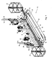
- the vehicle 10 consists essentially of a base body 12, which can be moved by two continuous winches 14 on two hoisting ropes 16 along a tower (not shown) of a wind turbine up and down, two safety ropes 18 to secure the vehicle 10, two foldable three-armed articulated arms 20, which at different heights at two opposite narrow sides of the base body 12 are arranged and equipped at their free end in each case with a work basket 22, two straps 24, which looped at a distance above and below the articulated arm 20 around the tower of the wind turbine and each stretched with two mounted on the base 12 winds 26 can be, and a total of four supports 30, with which the base body 12 is supported above and below the articulated arm 20 on the tower of the wind turbine.
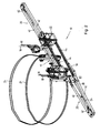
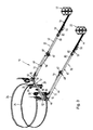
- the two foldable three-armed articulated arms 20 can each have a in Fig. 1 illustrated transport state, a in Fig. 2 shown driving state, as well as a variety of working states occupy, one of which in Fig. 3 and 4 is shown by way of example.
- transport condition Fig. 1
- the foldable articulated arms 20 are folded on a transport vehicle in such a way that they have a minimum length which is shorter than their length in the driving state (FIG. Fig. 2 ), and that in a longitudinal direction of the main body 12, only the working baskets 22 project beyond it, while the folded articulated arms abut against the broad side of the main body 12 facing away from the tower. laterally.
- the driving state Fig.
- the articulated arms 20 are also folded, but in a different configuration, so that they protrude longitudinally of the body 12 partially on this and the working baskets 22 in front of the far side facing away from the tower of the main body 12 are arranged.
- the center of gravity of the vehicle 10 is located in a vertical plane below the points of attack of the two hoisting ropes 16 so that essentially no moment is exerted about a longitudinal central axis of the vehicle 10 and the vehicle 10 hangs in a position on the hoisting ropes 16, in the the bottom of the work baskets 22 are aligned horizontally.
- the articulated arms 20 are pivoted outward from the base body 12, wherein the articulated arms 20 and their working baskets 22 can take a variety of different positions in which the articulated arms 20, at least when performing maintenance on a rotor blade far over that of the tower projecting away broad side of the base body 12.
- the articulated arms 20 are stretched and aligned generally perpendicular to the base body 12.
- the basic body 12 welded together from steel profiles consists essentially of a horizontal beam 32, and two inner and two outer vertical beams 34, 36 which are rigidly connected to the horizontal beam 32 and project laterally beyond the horizontal beam 32 at the lateral spacing ,
- the continuous winches 14 are mounted, with which the vehicle 10 is moved along the hoisting ropes 16 up and down.
- block stops 28 carry the upper ends of the outer vertical support 36 so-called block stops 28 through which the safety cables 18 extend.
- the two articulated arms 20 are attached.
- the two pairs of winches 26 are mounted at a vertical distance above or below the articulated arms 20, with which the straps surrounding the tower 24 can be stretched or loosened as needed.
- the two inner vertical support 34 on the tower side facing the four supports 30 are mounted in the form of two rollers with horizontal axes of rotation, with which the base body 12 is supported at strained straps 24 against the tower and in the driving state can roll on the tower surface.
- the two continuous winches 14 may, for example, be continuous winches, which are available under the name Tirak from the company Greifzug.
- the continuous winches 12 include magnetic brakes that automatically close in the event of a power failure and then prevent movement of the vehicle 10 along the hoisting ropes 16.
- the two block stops 28 lock mechanically when the vehicle 10 moves at too high speed on the safety ropes 18 down.
- the two foldable three-armed articulated arms 20 are made of fine-grained steel and each comprise a first, second and third articulated arm 40, 42, 44. Between the base body 12 and the first articulated arm 40 and between the first articulated arm 40 and the second articulated arm 42 is in each case a pivot joint 46, 48 is arranged with a vertical pivot axis, while between the second articulated arm 42 and the third articulated arm 44, a pivot joint 50 is arranged with a horizontal Schenkachse, so that the third articulated arm 44 with the work basket 22 with respect to the second articulated arm 42 up and down can be swiveled.
- a first hydraulic cylinder 52 is arranged, with which the entire articulated arm 20 can be pivoted horizontally with respect to the main body 12.
- a second hydraulic cylinder 54 is arranged, with which the second and third articulated arm 42, 44 and the working basket 20 with respect to the first articulated arm 40 can be pivoted horizontally.
- a third hydraulic cylinder 56 is arranged, with which the third articulated arm 44 and the working cage 22 with respect to the second Articulated arm 42 can be pivoted in a vertical plane.
- the cylinder tube 58 of the second hydraulic cylinder 54 is articulated on the first articulated arm 40, while the piston rod 60 is connected to both the first and the second articulated arm 40, 42 via a mechanical spreading mechanism 62.
- the spreading mechanism 62 By means of the spreading mechanism 62, the first and second articulated arms 40, 42 can be pivoted 180 degrees relative to each other.
- the third articulated arm 44 is pivotally attached to the underside of the work cage 22. How best in Fig. 4 and 9 illustrated, the third articulated arm 44 has a parallel link with two handlebars 66, which ensures during pivoting of the third articulated arm 44 that the work basket 22 maintains an orientation in which its bottom is horizontal.
- the first articulated arm 40 is composed of a first short arm part 70 which is pivotally connected to the main body 12 by the first pivot joint 46, and a second long arm part 72 pivotally connected to the first arm part 70 by a pivot pin 74 having a vertical pivot axis connected is.
- the second arm part 72 can be locked relative to the first arm part 70 by means of a locking pin 74 in two discrete pivoting positions, in which the locking pin 74 in each case passes through two bolt openings 76 in an extension 78 of the second arm part 72.
- a first pivot position ( Fig. 6 ) aligns the second arm portion 72 with the first arm portion 70, whereby the length of the articulated arm 20 can be maximized in the working states.
- the second arm part 72 In a second pivot position ( Fig. 5 ), the second arm part 72 is aligned approximately perpendicular to the first arm part 50, whereby in the transport state, the length of the folded articulated boom 20 can be shortened in order to reduce the footprint of the vehicle 20.
- the second articulated arm 42 consists of a first long arm part 80 which is pivotally connected to the first articulated arm 40 by the second pivot 48 and a second short arm part 82 on the end of the second articulated arm 42 adjacent to the third articulated arm 44 Arm member 82 is pivotally connected to first arm member 80 by a pivot pin 84 having a vertical pivot axis.
- the second arm part 82 can be locked by means of a locking bolt 86 with respect to the first arm part 80 in a first pivoting position (FIG. Fig. 8 and 9 ), in which the second arm part 82 is aligned with the first arm part 80. After removal of the locking pin 86, the second arm part 80 in a second pivot position ( Fig.
- the work basket-side end of the third articulated arm 44 of the one articulated arm 20 extends over the first short arm portion 70 of the first articulated arm 40 of the other articulated arm 20, while the working basket-side end of the third articulated arm 44 of the other articulated arm 20 is below the first short Arm portion 70 of the first articulated arm 40 of the one articulated arm 20 extends therethrough.
- the baskets 22 are in opposite directions Directions about the folded articulated arms 40, 42 over, which have been brought in the transport state in its second pivot position, in which the space or the length of the articulated arm 20 is the lowest.
- a control console (not shown) is provided in each of the two working baskets 22, which control console is connected to a control unit 20. With the control console, the hydraulic cylinder 52, 54, 56 can be controlled to bring the work basket 22 in a desired position.
- control consoles are connected in such a way that the hydraulic cylinders 52, 54, 56 of each articulated arm 20 can also be controlled by the control console in the work basket 22 of the other articulated arm 20, so that, for example, in the event of an accident involving a person in one of the two work baskets 22, his articulated arm 20 can be transferred from a person in the other work basket 22 back into the folded state of the vehicle, since the vehicle 20 can drive only in this state down.
- the control of the vehicle 20 is equipped with a safety circuit, on the one hand ensures that the two articulated arms 20 only then from the folded state of driving in a cantilevered Allow work to be transferred when the two straps 24 are tensioned and the winches 26 are locked or blocked by means of the integrated brakes.
- the safety circuit also ensures that the brakes of the two winches 26 can only be released when both articulated arms 20 are in the folded driving state.
- Each of the two straps 24, which wrap the tower vertically apart from each other, is a tear-resistant flat belt 24, the opposite ends of which are each wound on a take-up drum 84 of one of the winches 26.
- the strap 24 may be provided with a wear cover of rubber or other elastic or compliant material.
- the winches 26 each have an electric drive with a reversible direction of rotation, so that by driving the two winches 26, the belt 24 can be wound on the take-up drums 84 or unwound as needed to shorten or extend the loop length of the belt 24 to adapt them to the tower diameter at the height of the vehicle 20 or to tension the belt 24.
- Each winch 26 has an integrated brake or lock which locks the take-up drum 84 in the de-energized state of the winch 26 and prevents unwinding of the belt 24 from the drum 84 as long as no power is supplied to the winch 26.
- the upper strap 24 wraps around the tower at a vertical distance above the two articulated arms 20, while the lower strap 24 surrounds the tower slightly below the articulating arms 20. *** "
- the straps 24 serve to pull the main body 12 against the tower until the supports 30 are pressed against the tower.
- the upper belt 24 serves together with the two supports 30 arranged below the articulated arms 20 to intercept the moments exerted by the projecting articulated arms 20 in the working states on the base body 12 and to introduce them into the tower and thus prevent the working baskets 22 from swinging downwards.
- the lower belt is primarily used to prevent the vehicle 20 from rotating about an axis passing through the center of the body 12 and the tower when the moments exerted on the body by the articulated arms 20 are very different, for example because only one of the articulated arms 20 is extended.
- the supports 30 each consist of two superimposed rollers which are mounted at the top and at the bottom of the inner vertical support 34 so that they are pressed during clamping of one or both straps 24 against the base body 12 facing surface of the tower. At the same time, the rollers serve as guide rollers when the straps 24 are loosened or loosened in the driving state and the vehicle 10 is moved upwards or downwards along the hoisting ropes 16.
Abstract
Description
Die Erfindung betrifft eine Befahranlage zur Durchführung von Inspektions- und Wartungsarbeiten an turmartigen Bauwerken, insbesondere für Inspektions- und Wartungsarbeiten an Rotorblättern und Türmen von Windkraftanlagen, mit einem Grundkörper und mindestens einem faltbaren und/oder teleskopierbaren mehrarmigen Ausleger, der sich aus einem zusammengefalteten Befahrzustand in auskragende Arbeitszustände überführen lässt, wobei der Grundkörper entlang von mindestens einem Hubseil am Bauwerk auf und ab verfahrbar ist und sich zumindest in den Arbeitszuständen unterhalb des Auslegers gegen das Bauwerk abstützt.The invention relates to a vehicle for carrying out inspection and maintenance work on tower-like structures, in particular for inspection and maintenance of rotor blades and towers of wind turbines, with a base body and at least one foldable and / or telescopic multi-arm boom, resulting from a folded state in projecting cantilever states, wherein the body along at least one hoist rope on the building up and down and is supported at least in the working conditions below the boom against the building.
Es wurden bereits verschiedene Befahranlagen zur Durchführung von Inspektions- und Wartungsarbeiten an Rotorblättern von Windkraftanlagen vorgeschlagen. Viele dieser Befahranlagen, wie zum Beispiel die in der
Jedoch verursachen diese Befahranlagen mehrere Probleme. Erstens wird der Neigungswinkel der Hubseile immer flacher, je weiter die Befahranlage entlang des Rotorblatts nach oben gezogen wird und sich der Nabe nähert. Zweitens ist der Abstand zwischen dem Turm der Windkraftanlage und dem nach unten weisenden Rotorblatt in der Nähe der Nabe des Rotors sehr klein, so dass die Arbeitsbühne dort nicht mehr zwischen das Rotorblatt und den Turm der Windkraftanlage passt. Drittens lässt sich nicht bei allen Windkraftanlagen das zu wartende Rotorblatt vertikal bzw. parallel zum Turm ausrichten, was das Einführen oder Einfädeln des Rotorblatts in eine von der Arbeitsbühne umschlossene Öffnung unmöglich macht.However, these vehicles cause several problems. First, the inclination angle of the hoisting ropes becomes ever flatter, the farther the vehicle is pulled up along the rotor blade and approaches the hub. Second, the distance between the tower of the wind turbine and the downward-pointing rotor blade near the hub of the rotor is very small, so that the platform there no longer fits between the rotor blade and the tower of the wind turbine. Third, not all wind turbines can be serviced Align the rotor blade vertically or parallel to the tower, which makes it impossible to insert or thread the rotor blade into an opening enclosed by the working platform.
Um einen Teil dieser Probleme zu beseitigen, wurde in der
Bei dieser Befahranlage wird jedoch das große Gewicht und der große Platzbedarf der Führungs- und Hubeinheit als nachteilig angesehen, da sie größer dimensionierte Transportfahrzeuge und größer dimensionierte Winden zum Anheben der Befahranlage erforderlich machen.In this vehicle, however, the great weight and the large footprint of the guide and lifting unit is considered disadvantageous, as they make larger-sized transport vehicles and larger-sized winches for lifting the vehicle required.
Ausgehend hiervon liegt der Erfindung die Aufgabe zugrunde, eine Befahranlage der eingangs genannten Art dahingehend zu verbessern, dass ihr Gewicht und ihr Platzbedarf erheblich reduziert werden kann.Proceeding from this, the invention has the object, a vehicle of the type mentioned above to improve their weight and space requirements significantly.
Diese Aufgabe wird erfindungsgemäß durch mindestens eine das Bauwerk umgebende spannbare biegeschlaffe Umschlingung gelöst, die in einem Abstand oberhalb vom Ausleger am Grundkörper angreift.This object is achieved by at least one surrounding the structure tensionable pliable looping, which engages at a distance above the boom on the body.
Der Erfindung liegt der Gedanke zugrunde, dass sich das Gewicht und der Platzbedarf der Befahranlage erheblich verringern lassen, wenn zur Anpassung an variierende Turmdurchmesser eine spannbare biegeschlaffe Umschlingung verwendet wird, die sich vom Grundkörper aus um das Bauwerk herum erstreckt. Eine solche biegeschlaffe Umschlingung nimmt in aufgewickeltem Zustand nur wenig Platz ein und kann wegen ihres geringen Gewichts schnell und einfach um das Bauwerk herumgelegt werden, bevor die Befahranlage entlang des Turms nach oben verfahren wird. Wenn die Befahranlage nach oben oder unten versetzt werden soll, braucht die Umschlingung nur gelockert zu werden. Zudem kann ihre Länge einfach an variierende Turmdurchmesser angepasst werden. Zur Durchführung von Wartungs- oder Inspektionsarbeiten in einer gewünschten Höhe kann die biegeschlaffe Umschlingung gespannt werden, um die an den Hubseilen hängende Befahranlage in Bezug zum Turm zu fixieren, bevor der mindestens eine Ausleger in einen auskragenden Arbeitszustand überführt wird. Die gespannte Umschlingung verhindert zum einen durch Windkräfte verursachte kleine Bewegungen des Grundkörpers, die zu großen Bewegungsamplituden des Endes des Auslegers führen würden. Zum anderen wird beim Spannen der Umschlingung die Abstützung an das Bauwerk angenähert und gegen das Bauwerk gedrückt. Wenn die Enden der Umschlingung erfindungsgemäß in einem Abstand oberhalb von dem mindestens einen Ausleger am Grundkörper angreifen, umgibt die gespannte Umschlingung das Bauwerk oberhalb vom Ausleger. Wenn die Umschlingung das Bauwerk im Abstand oberhalb vom Ausleger umspannt und sich der Grundkörper unterhalb vom Ausleger gegen das Bauwerk abstützt, können die in den Arbeitszuständen vom auskragenden Ausleger auf den Grundkörper ausgeübten erheblichen Momente in Form von Zugkräften in die gespannte Umschlingung und in Form von Druckkräften in die Abstützung eingeleitet und von diesen weiter in das Bauwerk eingeleitet werden, um sie abzufangen und damit ein ungewolltes Absinken des freien Endes des Auslegers zu verhindern. Darüber hinaus kann durch die gespannte Umschlingung auch ein Teil der Gewichtskräfte der Befahranlage in das Bauwerk eingeleitet werden.The invention is based on the idea that the weight and the space requirement of the vehicle can be significantly reduced if a tensionable pliable loop is used to adapt to varying tower diameter, which extends from the body around the building around. Such a pliable loop takes up little space when wound up and, because of its low weight, can be quickly and easily wrapped around the building before the vehicle is moved upwards along the tower. If the vehicle is to be moved up or down, the wrap only needs to be relaxed. In addition, their length can be easily adapted to varying tower diameters. To perform maintenance or inspection work at a desired height, the pliable loop can be tensioned to fix the hanging on the hoist ropes in relation to the tower before the at least one boom is transferred to a cantilevered working state. The strained wrap prevents on the one hand caused by wind forces small movements of the body, which would lead to large amplitudes of movement of the end of the boom. On the other hand, during the tightening of the loop, the support is approximated to the building and pressed against the building. According to the invention, when the ends of the looping engage at a distance above the at least one extension arm on the base body, the tensioned looping surrounds the construction above the extension arm. If the wrap around the Structure spanned at a distance above the boom and the base is supported below the boom against the building, the exerted in the working states of the cantilever boom on the body considerable moments in the form of tensile forces in the strained loop and in the form of compressive forces in the support initiated and be further introduced by these in the building to intercept them, thereby preventing an unwanted drop in the free end of the boom. In addition, a part of the weight forces of the vehicle can be introduced into the structure by the strained looping.
Bei der biegeschlaffen Umschlingung kann es sich um ein Seil aus einem Material hoher Zugfestigkeit handeln, wie Nylon, Aramid oder Stahl, wobei das Seil zweckmäßig mit einer Umhüllung, zum Beispiele aus Gummi, versehen ist, um einen Verschleiß des gelockerten Seils bei der Auf- und Abbewegung entlang des Bauwerks zu verhindern. Alternativ handelt es sich bei der biegeschlaffen Umschlingung aber zweckmäßig um einen flachen Gurt, zum Beispiel einen Gewebegurt oder einen Gummigurt mit Gewebeeinlage. Darüber hinaus ist grundsätzlich auch die Verwendung einer Gliederkette als Umschlingung denkbar.The non-limber loop may be a rope of high tensile strength material, such as nylon, aramid or steel, the rope being suitably provided with a sheath, for example of rubber, to prevent wear of the loosened rope during the erection. and to prevent movement along the structure. Alternatively, however, the pliable looping is expediently a flat belt, for example a fabric belt or a rubber belt with fabric insert. In addition, in principle, the use of a link chain as wrapping conceivable.
Um die Länge der um das Bauwerk herum gelegten biegeschlaffen Umschlingung an variierende Querschnittsabmessungen des Bauwerks anzupassen, ist vorzugsweise mindestens ein Ende der Umschlingung um eine Trommel einer Winde herum gewickelt, so dass die Umschlingung nach Bedarf gespannt, gelockert oder abgewickelt werden kann. Die Winde kann als Durchlaufwinde ausgebildet sein und ist bevorzugt mit einer Bremse oder anderen Arretierung versehen, die ein ungewolltes Lockern der gespannten Umschlingung in den Arbeitszuständen verhindert. Um zu gewährleisten, dass die Zugkraft in der Umschlingung an beiden Enden ungefähr gleich groß ist, sind vorzugsweise zwei Winden vorgesehen, die sich zum Spannen der Umschlingung zweckmäßig gemeinsam antreiben lassen. Alternativ könnte zum Spannen und Lockern der Umschlingung allerdings auch ein Flaschenzug mit Zylinder oder eine Spindel verwendet werden.In order to adapt the length of the limp loop around the structure to varying cross-sectional dimensions of the structure, at least one end of the loop is preferably wrapped around a drum of a winch so that the wrap can be tensioned, slackened or unwound as needed. The winch may be designed as a continuous winch and is preferably provided with a brake or other locking, which prevents unwanted loosening of the strained loop in the working states. To ensure that the traction in the wrap around two ends are about the same size, two winches are preferably provided, which can be expediently driven together to tension the wrap. Alternatively, however, a pulley with a cylinder or a spindle could be used to tighten and loosen the wrap.
Dort, wo es sich bei der biegeschlaffen Umschlingung um ein Seil handelt, ist die Winde zweckmäßig eine Durchlaufwinde, von der aus das freie Seilende herabhängen kann. Dort, wo es sich bei der biegeschlaffen Umhüllung um einen Gurt oder eine Kette handelt, umfasst die Winde zweckmäßig eine Trommel, auf die der Gurt bzw. die Kette aufgewickelt wird.Where the limp loop is a rope, the winch is conveniently a continuous winch from which the free end of the rope can hang. Where the pliable sheath is a belt or a chain, the winch expediently comprises a drum on which the belt or the chain is wound up.
Eine weitere bevorzugte Ausgestaltung der Erfindung sieht vor, dass zwei getrennte spannbare biegeschlaffe Umschlingungen übereinander um das Bauwerk herumgelegt sind, so dass im Falle eines Versagens von einer Umschlingung zur Sicherheit eine weitere Umschlingung vorhanden ist. Diese kann dann die vom Ausleger ausgeübten Momente abfangen und in das Bauwerk einleiten. Dadurch wird verhindert, dass bei einem Versagen der Umschlingung der auskragende Ausleger mit dem Arbeitskorb nach unten schwingt. Die beiden Umschlingungen können in einem geringen Abstand übereinander angeordnet werden, so dass sie auf dieselbe Winde auf- und abgewickelt bzw. mit dieser gespannt werden können. Jedoch kann zwischen den Umschlingungen auch ein größerer vertikaler Abstand vorgesehen werden, wodurch die untere Umschlingung ein Seitwärtskippen der Befahranlage um eine etwa durch die Turmmitte verlaufende Achse verhindert, wenn ein einseitiges Moment auf den Grundkörper ausgeübt wird.A further preferred embodiment of the invention provides that two separate tensionable pliable looping around each other are wrapped around the building, so that in case of failure of a looping for security, a further looping is present. This can then intercept the moments exerted by the boom and initiate it into the structure. This will prevent the overhanging boom from swinging down to the work cage when the wrap fails. The two wraps can be arranged one above the other at a small distance so that they can be wound up and unwound or clamped onto the same winch. However, between the wraps and a greater vertical distance can be provided, whereby the lower loop prevents sideways tilting of the vehicle around a running approximately through the center of the tower axis when a one-sided moment is exerted on the body.
Die spannbare biegeschlaffe Umschlingung braucht nicht einstückig ausgebildet sein, sondern kann zweckmäßig auch aus zwei oder mehr miteinander verbundenen Teilstücken bestehen, so dass sie in Abhängigkeit von den Querschnittsabmessungen des Bauwerks durch Einsetzen oder Entnahme von einem oder mehreren Teilstücken verlängert oder verkürzt werden kann.The tensionable pliable loop does not need to be formed in one piece, but may suitably consist of two or more interconnected sections, so that they depend on the cross-sectional dimensions of the Building can be extended or shortened by inserting or removing one or more sections.
Eine weitere vorteilhafte Ausgestaltung der Erfindung sieht vor, dass die Befahranlage im Befahrzustand entlang von zwei Hubseilen am Bauwerk entlang nach oben und unten verfahrbar ist und dass im Befahrzustand Kraftangriffspunkte der beiden Hubseile und der Schwerpunkt der Befahranlage eine vertikale Ebene aufspannen, so dass im Befahrzustand der mindestens eine Ausleger bezüglich einer die Kraftangriffspunkte verbindenden Achse kein Moment auf den Grundkörper ausübt. Dadurch kann verhindert werden, dass die Befahranlage bei ihrer Auf- und Abwärtsbewegung um eine zwischen dem Turm und dem Grundkörper verlaufende Achse kippt.A further advantageous embodiment of the invention provides that the vehicle in driving condition along two hoisting ropes along the building along up and down is moved and that in the driving state force application points of the two hoisting ropes and the center of gravity of the vehicle a vertical plane span, so that in the state of the vehicle at least one arm exerts no moment on the base body with respect to an axis connecting the points of force application. This can prevent the vehicle from tipping over an axis extending between the tower and the main body during its up and down movement.
Wenn sich jedoch der mindestens eine Ausleger in einem auskragenden Arbeitszustand befindet, in dem er gestreckt und senkrecht zu der vertikalen Ebene durch die Kraftangriffspunkte der beiden Hubseile ausgerichtet ist, und wenn sich zudem eine Person in dem Arbeitskorb befindet, der dann in einem Abstand von mehr als 8 oder 9 Metern vom Grundkörper angeordnet ist, wirkt ein sehr großes Moment auf den Grundkörper ein. Dieses Moment wird über die Abstützung des Grundkörpers unterhalb des Auslegers und über die gespannte, das Bauwerk umgebende Umschlingung oberhalb des Auslegers aufgefangen, um ein Kippen der an den Hubseilen hängenden Befahranlage um eine zwischen dem Turm und dem Grundkörper verlaufende Achse zu verhindern.However, if the at least one boom is in a cantilevered working state in which it is stretched and aligned perpendicular to the vertical plane through the force application points of the two hoisting ropes, and also if a person is in the work cage, then at a distance of more is arranged as 8 or 9 meters from the body, a very large moment acts on the body. This moment is absorbed by the support of the body below the boom and on the strained, the structure surrounding loop above the boom to prevent tilting of hanging on the hoist ropes to a running between the tower and the body axis.
Um vor allem in den weit auskragenden Arbeitszuständen des mindestens einen Auslegers die Zugkräfte in der Umschlingung zu begrenzen, kann es sinnvoll sein, den vertikalen Abstand zwischen dem Ausleger und der oberhalb von diesem angeordneten Umschlingung und damit den Hebelarm des Moments, mit dem das Moment des Auslegers kompensiert wird, zu vergrößern. Dies ist möglich, wenn die Winden zum Spannen der biegeschlaffen Umschlingung und damit die Kraftangriffspunkte der letzteren in Bezug zum Grundkörper in vertikaler Richtung verstellbar sind, so dass sie unter Vergrößerung des vertikalen Abstands vom Ausleger nach oben gefahren werden können.In order to limit the tensile forces in the loop, especially in the cantilevered working states of the at least one boom, it may be useful, the vertical distance between the boom and the above this arranged wrap and thus the lever arm of the moment with which the moment of the Cantilever is compensated to enlarge. This is possible if the winches for tensioning the limp loop and thus the force application points of the latter are adjustable in relation to the base in the vertical direction, so that they can be driven by increasing the vertical distance from the boom upwards.
Um sicherzustellen, dass die Umschlingung immer gespannt ist, wenn sich der mindestens eine Ausleger in einem auskragenden Arbeitszustand befindet, sieht eine weitere vorteilhafte Ausgestaltung der Erfindung vor, dass die Befahranlage eine Steuerung umfasst, die einerseits ein Überführen des Auslegers aus dem zusammengefalteten Befahrzustand in einen Arbeitszustand erst bei gespannter Umschlingung ermöglicht und andererseits ein Lockern der Umschlingung erst nach dem Einfahren des Auslegers in den zusammengefalteten Befahrzustand zulässt.To ensure that the wrap is always tense when the at least one boom is in a cantilevered working state, provides a further advantageous embodiment of the invention that the access system includes a control, on the one hand, a transfer of the boom from the folded state in a vehicle Working state only possible with strained wrap and on the other hand, a loosening of the wrap only after the retraction of the boom in the folded state allows.
Gemäß einer weiteren bevorzugten Ausgestaltung der Erfindung umfasst die Befahranlage zwei allgemein gleich ausgebildete faltbare und/oder teleskopierbare mehrarmige Ausleger, die bevorzugt symmetrisch zu den Kraftangriffspunkten der Hubseile am Grundkörper befestigt sind, zweckmäßig in der Nähe von dessen entgegengesetzten Außenseiten, wo sie sich leichter am Rotorblatt vorbei in die auskragenden Arbeitzustände überführen lassen. Die Ausleger sind vorteilhaft in unterschiedlichen Höhen am Grundkörper angelenkt, so dass sie sich im zusammengefalteten Befahrzustand übereinander so eng wie möglich gegen den Grundkörper anlegen lassen.According to a further preferred embodiment of the invention, the traffic control system comprises two generally identically formed foldable and / or telescopic multi-arm boom, which are preferably symmetrically attached to the force application points of the hoisting ropes on the body, conveniently in the vicinity of its opposite outer sides, where it is easier on the rotor blade pass over into the overhanging work conditions. The booms are advantageously articulated at different heights on the base body, so that they can be put on each other in the folded state of driving one another as closely as possible against the base body.
Um den während der Befahrung eines Rotorblatts zum Lockern und Spannen der biegeschlaffen Umhüllung benötigten Zeitaufwand so gering wie möglich zu halten und die für die Wartungsarbeiten verfügbare Zeit zu maximieren, weist der oder jeder mehrarmige Ausleger vorteilhaft einen Gelenkarm auf, der um eine horizontale Schwenkachse in Bezug zum Grundkörper oder einem benachbarten Gelenkarm des Auslegers schwenkbar ist. Auf diese Weise kann die Reichweite bzw. der Arbeitsbereich eines am freien Ende des Auslegers montierter Arbeitskorbs in vertikaler Richtung erheblich vergrößert werden, wodurch die Befahranlage seltener umgesetzt werden muss.In order to minimize the amount of time required to navigate a rotor blade to loosen and tighten the pliable shroud and to maximize the time available for maintenance, the or each multi-arm cantilever advantageously has an articulated arm which extends around one horizontal pivot axis with respect to the main body or an adjacent articulated arm of the boom is pivotable. In this way, the range or the working area of a mounted at the free end of the boom work cage in the vertical direction can be significantly increased, making the car must be implemented less frequently.
Zwar ist der Arbeitsbereich des Auslegers in vertikaler Richtung am größten, wenn der nach oben und unten schwenkbare Gelenkarm direkt am Grundkörper angelenkt ist. Jedoch ist es arbeitstechnisch günstiger, den Arbeitskorb zuerst an das Rotorblatt heranzufahren und dann entlang des Rotorblatts nach oben und unten zu bewegen, weshalb der nach oben und unten schwenkbare Gelenkarm zweckmäßig der äußerste Gelenkarm des Auslegers ist. Dies gestattet es auch, den Arbeitskorb über den Befestigungspunkt des Hubseils am Bauwerk hinaus anzuheben, im Fall einer Windkraftanlage über die Unterseite der Nabe oder des Maschinenhauses hinaus. Der nach oben und unten schwenkbare Gelenkarm umfasst vorteilhaft einen Parallellenker oder anderen Lenker, der gewährleistet, dass der Arbeitskorb seine Ausrichtung beibehält, wenn der Gelenkarm nach oben oder unten geschwenkt wird.Although the working range of the boom in the vertical direction is greatest when the pivotable up and down articulated arm is hinged directly to the body. However, it is technically cheaper to bring the work cage first to the rotor blade and then move along the rotor blade up and down, which is why the pivotable up and down articulated arm is expediently the outermost articulated arm of the boom. This also makes it possible to raise the work basket beyond the point of attachment of the hoisting rope to the structure, in the case of a wind turbine beyond the bottom of the hub or the machine house. The upwardly and downwardly pivotable articulated arm advantageously includes a parallel link or other link that ensures that the platform retains its alignment when the articulated arm is pivoted up or down.
Um eine große Reichweite mit einer großen Bewegungsflexibilität zu kombinieren, umfasst jeder mehrarmige Ausleger vorteilhaft insgesamt drei Gelenkarme, von denen ein erster Gelenkarm um eine vertikale Schwenkachse schwenkbar am Grundkörper angelenkt ist, während ein zweiter Gelenkarm um eine vertikale Schwenkachse schwenkbar am Ende des ersten Gelenkarms und ein dritter Gelenkarm um eine horizontale Schwenkachse schwenkbar am Ende des zweiten Gelenkarms angelenkt ist. Das Verschwenken der Gelenkarme erfolgt mit Hilfe von Hydraulikzylindern. Zweckmäßig kann auch mindestens einer der Gelenkarme teleskopierbar sein, was eine weitere Vergrößerung des Arbeitsbereichs der Ausleger ermöglicht, jedoch auch deren Gewicht erhöht.To combine a long reach with a great flexibility of movement, each multi-arm boom advantageously comprises a total of three articulated arms, of which a first articulated arm is pivotally hinged about a vertical pivot axis on the main body, while a second articulated arm pivotable about a vertical pivot axis at the end of the first articulated arm and a third articulated arm is articulated pivotably about a horizontal pivot axis at the end of the second articulated arm. The pivoting of the articulated arms is done by means of hydraulic cylinders. Appropriately, at least one of the articulated arms can be telescoped, resulting in a further enlargement of the Work area of the boom allows, but also increases their weight.
Eine weitere bevorzugte Ausgestaltung der Erfindung sieht vor, dass mindestens einer der Gelenkarme ein geteilter Gelenkarm aus zwei Armteilen ist, die sich in zwei unterschiedlichen Stellungen starr miteinander verbinden oder kuppeln lassen. Während die beiden Armteile im Befahrzustand und in den Arbeitszuständen eine erste Stellung einnehmen, in der ihre Längsachsen zweckmäßig miteinander fluchten, nehmen die Armteile in einem Transportzustand der Befahranlage eine Stellung ein, in der sich die Abmessungen der Befahranlage verkleinern lassen, um den Platzbedarf beim Transport auf einem Anhänger oder einer Ladefläche eines Transportfahrzeugs zu minimieren. Vorteilhaft sind mindestens zwei der Gelenkarme geteilte Gelenkarme, deren Armteile schwenkbar miteinander verbunden sind und sich jeweils in zwei Schwenkstellungen in Bezug zueinander arretieren oder kuppeln lassen.A further preferred embodiment of the invention provides that at least one of the articulated arms is a split articulated arm of two arm parts, which can be rigidly connected or coupled together in two different positions. While the two arm parts occupy a first position in the driving state and in the working states, in which their longitudinal axes are aligned with each other, the arm parts assume a position in a transport state of the vehicle in which the dimensions of the vehicle can be reduced to the space required for transport to minimize on a trailer or a cargo bed of a transport vehicle. Advantageously, at least two of the articulated arms are divided articulated arms, whose arm parts are pivotally connected to each other and can each be locked or coupled in two pivotal positions with respect to each other.
Zweckmäßig ist der erste, mit dem Grundkörper verbundene Gelenkarm ein geteilter Gelenkarm, der aus einem am Grundkörper angelenkten ersten Armteil und einem zweiten Armteil besteht, der sich in einer ersten und in einer zweiten Schwenkstellung in Bezug zum ersten Armteil arretieren lässt. Der zweite Armteil ist in der ersten Schwenkstellung in Verlängerung des ersten Armteils angeordnet, so dass der erste Gelenkarm im Befahrzustand und in den Arbeitszuständen der Befahranlage gestreckt bzw. gerade ist. In der zweiten Schwenkstellung ist der zweite Armteil senkrecht zum ersten Armteil und parallel zu einer Längsseite des Grundkörpers ausgerichtet, gegen die er im Transportzustand der Befahranlage zweckmäßig anliegt, so dass er beim Transport auf einem Anhänger oder einer Ladefläche eines Transportfahrzeugs einen geringen Platzbedarf besitzt. Eine weitere vorteilhafte Ausgestaltung der Erfindung sieht vor, dass auch der zweite Gelenkarm ein geteilter Gelenkarm ist, der aus einem ersten Armteil und einem zweiten Armteil besteht. Der erste Armteil ist länger und schwenkbar mit dem ersten Gelenkarm verbunden, während der zweite Armteil kürzer und schwenkbar mit dem dritten Gelenkarm verbunden ist. Die beiden Armteile lassen sich in Bezug zueinander in einer ersten Schwenkstellung arretieren, in der ihre Längsachsen miteinander fluchten, so dass die beiden Armteile im Befahrzustand und in den Arbeitszuständen gestreckt sind, sowie in einer zweiten Schwenkstellung, in der sie in allgemein paralleler Ausrichtung nebeneinander angeordnet sind, um den Platzbedarf bzw. die Länge der Ausleger im Transportzustand zu minimieren.Suitably, the first articulated arm connected to the main body is a split articulated arm which consists of a first arm part articulated on the main body and a second arm part which can be locked in a first and in a second pivotal position with respect to the first arm part. The second arm part is arranged in the first pivoting position in extension of the first arm part, so that the first articulated arm is stretched or straight in the driving state and in the operating states of the vehicle. In the second pivot position of the second arm is aligned perpendicular to the first arm and parallel to a longitudinal side of the body against which it is appropriate in the transport condition of the vehicle, so that it has a small footprint when transported on a trailer or a cargo area of a transport vehicle. A further advantageous embodiment of the invention provides that the second articulated arm is also a divided articulated arm, which consists of a first arm part and a second arm part. The first arm part is longer and pivotally connected to the first articulated arm, while the second arm part is shorter and pivotally connected to the third articulated arm. The two arm parts can be locked in relation to each other in a first pivot position, in which their longitudinal axes are aligned so that the two arm parts are stretched in the on-state and in the working states, as well as in a second pivot position in which they are arranged side by side in generally parallel orientation are to minimize the space requirement or the length of the boom in the transport state.
Im Folgenden wird die Erfindung anhand eines in der Zeichnung dargestellten Ausführungsbeispiels näher erläutert.
-
Fig. 1 zeigt eine perspektivische Ansicht einer Befahranlage zur Durchführung von Inspektions- und Wartungsarbeiten an Rotorblättern und Türmen von Windkraftanlagen in einem Transportzustand; -
Fig. 2 zeigt eine perspektivische Ansicht der Befahranlage in einem Befahrzustand, in dem die Befahranlage am Turm der Windkraftanlage nach oben und unten verfahren wird; -
Fig. 3 zeigt eine perspektivische Ansicht der Befahranlage in einem beispielhaften Arbeitszustand, in dem zwei mehrarmige Gelenkausleger zur Durchführung von Wartungsarbeiten an einem Rotorblatt nebeneinander gestreckt und gerade über einen Grundkörper auskragen; -
Fig. 4 zeigt eine perspektivische Ansicht von einem der beiden Gelenkausleger; -
Fig. 5 zeigt eine teilweise weg geschnittene vergrößerte perspektivische Ansicht von Teilen eines Gelenkauslegers im Transportzustand; -
Fig. 6 zeigt eine teilweise weg geschnittene weiter vergrößerte perspektivische Ansicht von zwei Armteilen eines ersten Gelenkarms eines Gelenkauslegers im Befahrzustand; -
Fig. 7 zeigt eine Draufsicht auf einen ersten und einen zweiten Gelenkarm eines Gelenkauslegers im Transportzustand; -
Fig. 8 zeigt eine teilweise weg geschnittene weiter vergrößerte perspektivische Ansicht von zwei Armteilen eines dritten Gelenkarms eines Gelenkauslegers im Befahrzustand; -
Fig. 9 zeigt eine teilweise weg geschnittene vergrößerte perspektivische Ansicht von Teilen des dritten Gelenkarms eines Gelenkauslegers im Befahrzustand.
-
Fig. 1 shows a perspective view of a vehicle for performing inspection and maintenance of rotor blades and towers of wind turbines in a transport state; -
Fig. 2 shows a perspective view of the vehicle in a driving state in which the access system is moved up and down the tower of the wind turbine; -
Fig. 3 shows a perspective view of the vehicle in an exemplary working state in which two multi-arm articulated arms for performing maintenance work on a rotor blade stretched side by side and project straight over a base body; -
Fig. 4 shows a perspective view of one of the two articulated arms; -
Fig. 5 shows a partially cut away enlarged perspective view of parts of a hinge arm in the transport state; -
Fig. 6 shows a partially cutaway further enlarged perspective view of two arm parts of a first articulated arm of a hinge arm in the vehicle state; -
Fig. 7 shows a plan view of a first and a second articulated arm of a joint arm in the transport state; -
Fig. 8 shows a partially cutaway further enlarged perspective view of two arm parts of a third articulated arm of a hinge arm in the vehicle state; -
Fig. 9 shows a partially cut away enlarged perspective view of parts of the third articulated arm of a hinge arm in the vehicle state.
Die in der Zeichnung dargestellte Befahranlage 10 dient vor allem zur Durchführung von Inspektions- und Wartungsarbeiten an Rotorblättern und Türmen von Windkraftanlagen, kann jedoch auch bei Inspektions- und Wartungsarbeiten an anderen hohen Bauwerken, wie Fernsehtürmen oder Schornsteinen eingesetzt werden.The vehicle shown in the drawing 10 is mainly used to carry out inspection and maintenance of rotor blades and towers of wind turbines, but can also be used in inspection and maintenance of other tall structures, such as television towers or chimneys.
Wie am besten in den
Die beiden faltbaren dreiarmigen Gelenkausleger 20 können jeweils einen in
Der aus Stahlprofilen zusammengeschweißte Grundkörper 12 besteht im Wesentlichen aus einem Horizontalträger 32, sowie zwei inneren und zwei äußeren Vertikalträgern 34, 36, die starr mit dem Horizontalträger 32 verbunden sind und im seitlichen Abstand voneinander nach oben und teilweise auch nach unten über den Horizontalträger 32 überstehen. An den oberen Enden der beiden äußeren Vertikalträger 36 sind die Durchlaufwinden 14 angebracht, mit denen die Befahranlage 10 entlang der Hubseile 16 nach oben und unten verfahren wird. Weiter tragen die oberen Enden der äußeren Vertikalträger 36 so genannte Blockstops 28, durch welche die Sicherungsseile 18 verlaufen. An den unteren Enden der beiden äußeren Vertikalträger 36 sind die beiden Gelenkausleger 20 angebracht. An den oberen und unteren Enden der beiden inneren Vertikalträger 34 sind im vertikalen Abstand oberhalb bzw. unterhalb der Gelenkausleger 20 die beiden Paare von Winden 26 angebracht, mit denen die den Turm umgebenden Gurte 24 nach Bedarf gespannt oder gelockert werden können. An den oberen und unteren Enden der beiden inneren Vertikalträger 34 sind auf der Turm zugewandten Seite auch die vier Abstützungen 30 in Form von je zwei Rollen mit horizontalen Drehachsen angebracht, mit denen sich der Grundkörper 12 bei gespannten Gurten 24 gegen den Turm abstützt und im Befahrzustand auf der Turmoberfläche abrollen kann.The
Bei den beiden Durchlaufwinden 14 kann es sich zum Beispiel um Durchlaufwinden handeln, die unter der Bezeichnung Tirak von der Firma Greifzug erhältlich sind. Die Durchlaufwinden 12 umfassen Magnetbremsen, die sich bei einem Stromausfall selbsttätig schließen und dann eine Bewegung der Befahranlage 10 entlang der Hubseile 16 verhindern. Die beiden Blockstops 28 blockieren mechanisch, wenn sich die Befahranlage 10 mit zu hoher Geschwindigkeit an den Sicherungsseilen 18 abwärts bewegt.The two
Die beiden faltbaren dreiarmigen Gelenkausleger 20 sind aus Feinkornstahl hergestellt und umfassen jeweils einen ersten, zweiten und dritten Gelenkarm 40, 42, 44. Zwischen dem Grundkörper 12 und dem ersten Gelenkarm 40 sowie zwischen dem ersten Gelenkarm 40 und dem zweiten Gelenkarm 42 ist jeweils ein Schwenkgelenk 46, 48 mit einer vertikalen Schwenkachse angeordnet, während zwischen dem zweiten Gelenkarm 42 und dem dritten Gelenkarm 44 ein Schwenkgelenk 50 mit einer horizontalen Schenkachse angeordnet ist, so dass der dritte Gelenkarm 44 mit dem Arbeitskorb 22 in Bezug zum zweiten Gelenkarm 42 nach oben und unten geschwenkt werden kann.The two foldable three-armed articulated
Zwischen dem Grundkörper 12 und dem ersten Gelenkarm 40 jedes Gelenkauslegers 20 ist ein erster Hydraulikzylinder 52 angeordnet, mit dem der gesamte Gelenkausleger 20 in Bezug zum Grundkörper 12 horizontal verschwenkt werden kann. Zwischen dem ersten und zweiten Gelenkarm 40, 42 jedes Gelenkauslegers 20 ist ein zweiter Hydraulikzylinder 54 angeordnet, mit dem der zweite und dritte Gelenkarm 42, 44 sowie der Arbeitskorb 20 in Bezug zum ersten Gelenkarm 40 horizontal verschwenkt werden können. Zwischen dem zweiten und dritten Gelenkarm 42, 44 ist ein dritter Hydraulikzylinder 56 angeordnet, mit dem der dritte Gelenkarm 44 und der Arbeitskorb 22 in Bezug zum zweiten Gelenkarm 42 in einer vertikalen Ebene verschwenkt werden können.Between the
Wie am besten in
Der dritte Gelenkarm 44 ist schwenkbar an der Unterseite des Arbeitskorbs 22 befestigt. Wie am besten in
Wie am besten in den
Wie am besten in den
Wie in
Zur Steuerung der Bewegung der Gelenkarme 40, 42, 44 jedes Gelenkauslegers 20 ist in jedem der beiden Arbeitskörbe 22 eine Steuerkonsole (nicht dargestellt) vorgesehen, die mit einer Steuerung der Befahranlage 20 verbunden ist. Mit der Steuerkonsole lassen sich die Hydraulikzylinder 52, 54, 56 ansteuern, um den Arbeitskorb 22 in eine gewünschte Position zu bringen. Die Steuerkonsolen sind so geschaltet, dass die Hydraulikzylinder 52, 54, 56 jedes Gelenkauslegers 20 auch von der Steuerkonsole im Arbeitskorb 22 des anderen Gelenkauslegers 20 gesteuert werden können, so dass zum Beispiel bei einem Unfall einer Person in einem der beiden Arbeitskörbe 22 dessen Gelenkausleger 20 von einer Person im anderen Arbeitskorb 22 zurück in den zusammengefalteten Befahrzustand überführt werden kann, da sich die Befahranlage 20 nur in diesem Zustand nach unten fahren lässt.To control the movement of the articulated
Von den Steuerkonsolen der Arbeitskörbe aus ist es jedoch nicht möglich, die Winden 26 der Gurte 24 oder die Durchlaufwinden 14 der Hubseile 16 zu steuern, wodurch ein unbeabsichtigtes Lockern der Gurte 24 in einem Arbeitszustand der Gelenkausleger 24 verhindert werden kann. Die Steuerung der Winden 26 der Gurte 24 und der Durchlaufwinden 14 der Hubseile 16 erfolgt an einer Haupt-Steuerkonsole (nicht dargestellt), die im Befahrzustand von einem der Arbeitskörbe 22 aus zugänglich ist.From the control consoles of the work baskets, however, it is not possible to control the
Weiter ist die Steuerung der Befahranlage 20 mit einer Sicherheitsschaltung ausgestattet, die einerseits sicherstellt, dass sich die beiden Gelenkausleger 20 erst dann aus dem zusammengefalteten Befahrzustand in einen auskragenden Arbeitszustand überführen lassen, wenn die beiden Gurte 24 gespannt und die Winden 26 mittels der integrierten Bremsen arretiert oder blockiert sind. Die Sicherheitsschaltung sorgt andererseits auch dafür, dass die Bremsen der beiden Winden 26 nur dann gelöst werden können, wenn sich beide Gelenkausleger 20 im zusammengefalteten Befahrzustand befinden.Next, the control of the
Bei jedem der beiden Gurte 24, die den Turm im vertikalen Abstand voneinander umschlingen, handelt es sich um einen reißfesten flachen Gewebegurt 24, dessen entgegengesetzte Enden jeweils auf eine Aufwickeltrommel 84 von einer der Winden 26 aufgewickelt sind. Der Gurt 24 kann mit einem Verschleißüberzug aus Gummi oder einem anderen elastischen oder nachgiebigen Material versehen sein. Die Winden 26 besitzen jeweils einen elektrischen Antrieb mit umkehrbarer Drehrichtung, so dass durch Antreiben der beiden Winden 26 der Gurt 24 nach Bedarf auf die Aufwickeltrommeln 84 aufgewickelt bzw. von diesen abgewickelt werden kann, die Umschlingungslänge des Gurts 24 zur verkürzen oder zu verlängern, um sie an den Turmdurchmesser in der Höhe der Befahranlage 20 anzupassen oder um den Gurt 24 zu spannen. Jede Winde 26 besitzt eine integrierte Bremse oder Arretierung, welche die Aufwickeltrommel 84 im stromlosen Zustand der Winde 26 blockiert und ein Abwickeln des Gurts 24 von der Trommel 84 verhindert, solange der Winde 26 kein Strom zugeführt wird.Each of the two
Der obere Gurt 24 umschlingt den Turm in einem vertikalen Abstand oberhalb von den beiden Gelenkauslegern 20, während der untere Gurt 24 den Turm etwas unterhalb von den Gelenkauslegern 20 umgibt.The
In gespanntem Zustand dienen die Gurte 24 dazu, den Grundkörper 12 gegen den Turm zu ziehen, bis die Abstützungen 30 gegen den Turm angepresst werden. Weiter dient der obere Gurt 24 zusammen mit den beiden unterhalb der Gelenkausleger 20 angeordneten Abstützungen 30 dazu, die von den auskragenden Gelenkauslegern 20 in den Arbeitszuständen auf den Grundkörper 12 ausgeübten Momente abzufangen und in den Turm einzuleiten und damit zu verhindern, dass die Arbeitskörbe 22 nach unten schwingen. Der untere Gurt dient hauptsächlich dazu, ein Verdrehen der Befahranlage 20 um eine durch die Mitte des Grundkörpers 12 und des Turms verlaufende Achse zu verhindern, wenn die von den Gelenkauslegern 20 auf den Grundkörper ausgeübten Momente sehr unterschiedlich sind, zum Beispiel weil nur einer der Gelenkausleger 20 ausgefahren ist.In the tensioned state, the
Die Abstützungen 30 bestehen jeweils aus zwei übereinander angeordneten Rollen, die so am oberen und am unteren Ende der inneren Vertikalträger 34 angebracht sind, dass sie beim Spannen eines oder beider Gurte 24 gegen die dem Grundkörper 12 zugewandte Oberfläche des Turms angepresst werden. Die Rollen dienen zugleich als Führungsrollen, wenn im Befahrzustand die Gurte 24 gelöst oder gelockert sind und die Befahranlage 10 an den Hubseilen 16 entlang nach oben oder nach unten bewegt wird.The supports 30 each consist of two superimposed rollers which are mounted at the top and at the bottom of the inner
Claims (14)
Priority Applications (1)
| Application Number | Priority Date | Filing Date | Title |
|---|---|---|---|
| EP12005606.4A EP2693045A1 (en) | 2012-08-01 | 2012-08-01 | Access system for performing inspection and maintenance work on tower-like structures |
Applications Claiming Priority (1)
| Application Number | Priority Date | Filing Date | Title |
|---|---|---|---|
| EP12005606.4A EP2693045A1 (en) | 2012-08-01 | 2012-08-01 | Access system for performing inspection and maintenance work on tower-like structures |
Publications (1)
| Publication Number | Publication Date |
|---|---|
| EP2693045A1 true EP2693045A1 (en) | 2014-02-05 |
Family
ID=47002477
Family Applications (1)
| Application Number | Title | Priority Date | Filing Date |
|---|---|---|---|
| EP12005606.4A Withdrawn EP2693045A1 (en) | 2012-08-01 | 2012-08-01 | Access system for performing inspection and maintenance work on tower-like structures |
Country Status (1)
| Country | Link |
|---|---|
| EP (1) | EP2693045A1 (en) |
Cited By (6)
| Publication number | Priority date | Publication date | Assignee | Title |
|---|---|---|---|---|
| CN106088566A (en) * | 2016-06-03 | 2016-11-09 | 江苏科技大学 | A kind of for wind-power tower maintenance and the emergency protective device of operation platform |
| CN107975460A (en) * | 2017-12-01 | 2018-05-01 | 刘艳 | Wind power generation unit blade maintenance device |
| CN110998042A (en) * | 2017-07-05 | 2020-04-10 | 安利马克集团管理公司 | Transport system, elevator system, kit, tower section and method for performing an assembly or maintenance operation in a tower |
| WO2022112111A1 (en) * | 2020-11-26 | 2022-06-02 | Pp Energy Aps | Tower guide arrangement for a wind turbine blade access platform |
| WO2022112121A1 (en) * | 2020-11-26 | 2022-06-02 | Pp Energy Aps | Tower guide arrangement for a wind turbine blade access platform |
| CN116767073A (en) * | 2023-08-22 | 2023-09-19 | 华能新能源股份有限公司山西分公司 | Road support transportation trailer for assembling wind generating set accessories |
Citations (12)
| Publication number | Priority date | Publication date | Assignee | Title |
|---|---|---|---|---|
| US2309769A (en) * | 1941-09-12 | 1943-02-02 | Chance Co Ab | Transformer gin |
| US4243350A (en) * | 1978-02-06 | 1981-01-06 | Hall Robert E | Winch load fastening apparatus |
| FR2702752A1 (en) * | 1993-03-17 | 1994-09-23 | Hiviaco 88 | Lifting device for cradle for transporting individuals |
| DE19647515A1 (en) * | 1996-11-16 | 1998-05-20 | Otto Gerd Albrecht | Wind-power unit erection equipment |
| WO2004081373A2 (en) | 2003-03-11 | 2004-09-23 | aeroconcept Ingenieurgesellschaft für Luftfahrttechnik und Faserverbundtechnologie mbH | Maintenance platform |
| WO2005064152A2 (en) | 2003-12-30 | 2005-07-14 | Pp Energy Aps | Device for enabling access to a structure above ground level |
| WO2007085265A1 (en) | 2006-01-27 | 2007-08-02 | Pp Energy Aps | Device for enabling access to a structure above ground level |
| US20090110531A1 (en) * | 2007-10-25 | 2009-04-30 | Yeary Enoch R | Elevated sports stand for the handicapped |
| US20090272709A1 (en) * | 2008-05-02 | 2009-11-05 | Nessner Thomas J | Portable pillar-mountable hoist |
| WO2010136026A2 (en) | 2009-05-29 | 2010-12-02 | Ebf Dresden Gmbh | Device for inspection and maintenance work on rotor blades and/or the tower surface of large wind power plants, particularly off-shore plants |
| US8062106B1 (en) * | 2009-03-25 | 2011-11-22 | C.E. Smith Co., Inc. | Lifting holder for an animal feeder |
| EP2394947A1 (en) | 2010-06-10 | 2011-12-14 | Special Blade Service B.V. | Platform for wind turbine |
-
2012
- 2012-08-01 EP EP12005606.4A patent/EP2693045A1/en not_active Withdrawn
Patent Citations (12)
| Publication number | Priority date | Publication date | Assignee | Title |
|---|---|---|---|---|
| US2309769A (en) * | 1941-09-12 | 1943-02-02 | Chance Co Ab | Transformer gin |
| US4243350A (en) * | 1978-02-06 | 1981-01-06 | Hall Robert E | Winch load fastening apparatus |
| FR2702752A1 (en) * | 1993-03-17 | 1994-09-23 | Hiviaco 88 | Lifting device for cradle for transporting individuals |
| DE19647515A1 (en) * | 1996-11-16 | 1998-05-20 | Otto Gerd Albrecht | Wind-power unit erection equipment |
| WO2004081373A2 (en) | 2003-03-11 | 2004-09-23 | aeroconcept Ingenieurgesellschaft für Luftfahrttechnik und Faserverbundtechnologie mbH | Maintenance platform |
| WO2005064152A2 (en) | 2003-12-30 | 2005-07-14 | Pp Energy Aps | Device for enabling access to a structure above ground level |
| WO2007085265A1 (en) | 2006-01-27 | 2007-08-02 | Pp Energy Aps | Device for enabling access to a structure above ground level |
| US20090110531A1 (en) * | 2007-10-25 | 2009-04-30 | Yeary Enoch R | Elevated sports stand for the handicapped |
| US20090272709A1 (en) * | 2008-05-02 | 2009-11-05 | Nessner Thomas J | Portable pillar-mountable hoist |
| US8062106B1 (en) * | 2009-03-25 | 2011-11-22 | C.E. Smith Co., Inc. | Lifting holder for an animal feeder |
| WO2010136026A2 (en) | 2009-05-29 | 2010-12-02 | Ebf Dresden Gmbh | Device for inspection and maintenance work on rotor blades and/or the tower surface of large wind power plants, particularly off-shore plants |
| EP2394947A1 (en) | 2010-06-10 | 2011-12-14 | Special Blade Service B.V. | Platform for wind turbine |
Cited By (8)
| Publication number | Priority date | Publication date | Assignee | Title |
|---|---|---|---|---|
| CN106088566A (en) * | 2016-06-03 | 2016-11-09 | 江苏科技大学 | A kind of for wind-power tower maintenance and the emergency protective device of operation platform |
| CN110998042A (en) * | 2017-07-05 | 2020-04-10 | 安利马克集团管理公司 | Transport system, elevator system, kit, tower section and method for performing an assembly or maintenance operation in a tower |
| CN110998042B (en) * | 2017-07-05 | 2021-06-22 | 安利马克集团管理公司 | Transport system, kit and method for performing assembly or maintenance operations in a tower structure |
| CN107975460A (en) * | 2017-12-01 | 2018-05-01 | 刘艳 | Wind power generation unit blade maintenance device |
| WO2022112111A1 (en) * | 2020-11-26 | 2022-06-02 | Pp Energy Aps | Tower guide arrangement for a wind turbine blade access platform |
| WO2022112121A1 (en) * | 2020-11-26 | 2022-06-02 | Pp Energy Aps | Tower guide arrangement for a wind turbine blade access platform |
| CN116767073A (en) * | 2023-08-22 | 2023-09-19 | 华能新能源股份有限公司山西分公司 | Road support transportation trailer for assembling wind generating set accessories |
| CN116767073B (en) * | 2023-08-22 | 2023-10-20 | 华能新能源股份有限公司山西分公司 | Road support transportation trailer for assembling wind generating set accessories |
Similar Documents
| Publication | Publication Date | Title |
|---|---|---|
| EP1815136B1 (en) | Device and method for mounting and/or dismantling a component of a wind turbine | |
| EP2364948B1 (en) | Crane | |
| EP1666401B1 (en) | Mobile crane | |
| DE10022658B4 (en) | telescopic crane | |
| EP2308792B1 (en) | Crane with a boom tensioning device | |
| EP2693045A1 (en) | Access system for performing inspection and maintenance work on tower-like structures | |
| DE102009005632B4 (en) | Handling of rotor blades | |
| EP2248754A1 (en) | Telescopic crane with self-fittable slackening device and fitting method for a slackening device | |
| EP2723670B1 (en) | Load handling apparatus for lifting, and method for mounting, rotor blades of a wind turbine | |
| EP3132137B1 (en) | Mobile crane device and method for the temporary assembly of such a crane device | |
| DE102010023275B4 (en) | Procedure for moving large cranes in the upgraded system and system for performing this procedure | |
| DE202005005627U1 (en) | Crane with anchoring device for moving loads has at least one anchoring support fixed to rocker cylinder | |
| DE102015009156B4 (en) | Telescopic boom of a crane with guy as well as crane | |
| WO2015090282A1 (en) | Retaining, lifting, and securing device for attaching to tall tower-like structures | |
| DE102010060639A1 (en) | Working platform system for complete inspection of rotor blades of wind power plants, has carrier device comprising movable suspension device, and working platform containing approximate horizontal position even during irregular loading | |
| DE202005019439U1 (en) | Lifting platform for maintenance of rotor blades of windmills with basic frame as support and rope hoist with bracing cables for movement of platform along blade length | |
| DE202005016743U1 (en) | Crane comprises a bracing device having two brace supports hinged on an auxiliary boom and inclined opposite a rocker surface | |
| DE20218971U1 (en) | Mobile crane with long arms | |
| EP2897892B1 (en) | Method for operating a crane, and crane | |
| DE2106291C3 (en) | Tower crane | |
| EP2984024B1 (en) | Folding crane jib and crane | |
| DE3401094C2 (en) | Crane with telescopic tower | |
| DE102019122071B3 (en) | Telescopic boom with fold-out mast | |
| DE102019131914B4 (en) | Crane with luffing boom extension | |
| DE102010046403B4 (en) | Method for maneuvering and moving a vehicle crane |
Legal Events
| Date | Code | Title | Description |
|---|---|---|---|
| AK | Designated contracting states |
Kind code of ref document: A1 Designated state(s): AL AT BE BG CH CY CZ DE DK EE ES FI FR GB GR HR HU IE IS IT LI LT LU LV MC MK MT NL NO PL PT RO RS SE SI SK SM TR |
|
| AX | Request for extension of the european patent |
Extension state: BA ME |
|
| PUAI | Public reference made under article 153(3) epc to a published international application that has entered the european phase |
Free format text: ORIGINAL CODE: 0009012 |
|
| STAA | Information on the status of an ep patent application or granted ep patent |
Free format text: STATUS: THE APPLICATION IS DEEMED TO BE WITHDRAWN |
|
| 18D | Application deemed to be withdrawn |
Effective date: 20140806 |