EP2693045A1 - Système de déplacement destiné à réaliser des travaux d'inspection et d'entretien sur des bâtiments de type tour - Google Patents
Système de déplacement destiné à réaliser des travaux d'inspection et d'entretien sur des bâtiments de type tour Download PDFInfo
- Publication number
- EP2693045A1 EP2693045A1 EP12005606.4A EP12005606A EP2693045A1 EP 2693045 A1 EP2693045 A1 EP 2693045A1 EP 12005606 A EP12005606 A EP 12005606A EP 2693045 A1 EP2693045 A1 EP 2693045A1
- Authority
- EP
- European Patent Office
- Prior art keywords
- arm
- articulated
- control system
- access control
- articulated arm
- Prior art date
- Legal status (The legal status is an assumption and is not a legal conclusion. Google has not performed a legal analysis and makes no representation as to the accuracy of the status listed.)
- Withdrawn
Links
Images


Classifications
-
- B—PERFORMING OPERATIONS; TRANSPORTING
- B66—HOISTING; LIFTING; HAULING
- B66C—CRANES; LOAD-ENGAGING ELEMENTS OR DEVICES FOR CRANES, CAPSTANS, WINCHES, OR TACKLES
- B66C23/00—Cranes comprising essentially a beam, boom, or triangular structure acting as a cantilever and mounted for translatory of swinging movements in vertical or horizontal planes or a combination of such movements, e.g. jib-cranes, derricks, tower cranes
- B66C23/18—Cranes comprising essentially a beam, boom, or triangular structure acting as a cantilever and mounted for translatory of swinging movements in vertical or horizontal planes or a combination of such movements, e.g. jib-cranes, derricks, tower cranes specially adapted for use in particular purposes
- B66C23/20—Cranes comprising essentially a beam, boom, or triangular structure acting as a cantilever and mounted for translatory of swinging movements in vertical or horizontal planes or a combination of such movements, e.g. jib-cranes, derricks, tower cranes specially adapted for use in particular purposes with supporting couples provided by walls of buildings or like structures
- B66C23/207—Cranes comprising essentially a beam, boom, or triangular structure acting as a cantilever and mounted for translatory of swinging movements in vertical or horizontal planes or a combination of such movements, e.g. jib-cranes, derricks, tower cranes specially adapted for use in particular purposes with supporting couples provided by walls of buildings or like structures with supporting couples provided by wind turbines
-
- B—PERFORMING OPERATIONS; TRANSPORTING
- B66—HOISTING; LIFTING; HAULING
- B66F—HOISTING, LIFTING, HAULING OR PUSHING, NOT OTHERWISE PROVIDED FOR, e.g. DEVICES WHICH APPLY A LIFTING OR PUSHING FORCE DIRECTLY TO THE SURFACE OF A LOAD
- B66F11/00—Lifting devices specially adapted for particular uses not otherwise provided for
- B66F11/04—Lifting devices specially adapted for particular uses not otherwise provided for for movable platforms or cabins, e.g. on vehicles, permitting workmen to place themselves in any desired position for carrying out required operations
- B66F11/044—Working platforms suspended from booms
-
- E—FIXED CONSTRUCTIONS
- E04—BUILDING
- E04G—SCAFFOLDING; FORMS; SHUTTERING; BUILDING IMPLEMENTS OR AIDS, OR THEIR USE; HANDLING BUILDING MATERIALS ON THE SITE; REPAIRING, BREAKING-UP OR OTHER WORK ON EXISTING BUILDINGS
- E04G3/00—Scaffolds essentially supported by building constructions, e.g. adjustable in height
- E04G3/24—Scaffolds essentially supported by building constructions, e.g. adjustable in height specially adapted for particular parts of buildings or for buildings of particular shape, e.g. chimney stacks or pylons
- E04G3/243—Scaffolds essentially supported by building constructions, e.g. adjustable in height specially adapted for particular parts of buildings or for buildings of particular shape, e.g. chimney stacks or pylons following the outside contour of a building
-
- E—FIXED CONSTRUCTIONS
- E04—BUILDING
- E04G—SCAFFOLDING; FORMS; SHUTTERING; BUILDING IMPLEMENTS OR AIDS, OR THEIR USE; HANDLING BUILDING MATERIALS ON THE SITE; REPAIRING, BREAKING-UP OR OTHER WORK ON EXISTING BUILDINGS
- E04G3/00—Scaffolds essentially supported by building constructions, e.g. adjustable in height
- E04G3/28—Mobile scaffolds; Scaffolds with mobile platforms
- E04G3/30—Mobile scaffolds; Scaffolds with mobile platforms suspended by flexible supporting elements, e.g. cables
-
- F—MECHANICAL ENGINEERING; LIGHTING; HEATING; WEAPONS; BLASTING
- F03—MACHINES OR ENGINES FOR LIQUIDS; WIND, SPRING, OR WEIGHT MOTORS; PRODUCING MECHANICAL POWER OR A REACTIVE PROPULSIVE THRUST, NOT OTHERWISE PROVIDED FOR
- F03D—WIND MOTORS
- F03D80/00—Details, components or accessories not provided for in groups F03D1/00 - F03D17/00
- F03D80/50—Maintenance or repair
-
- Y—GENERAL TAGGING OF NEW TECHNOLOGICAL DEVELOPMENTS; GENERAL TAGGING OF CROSS-SECTIONAL TECHNOLOGIES SPANNING OVER SEVERAL SECTIONS OF THE IPC; TECHNICAL SUBJECTS COVERED BY FORMER USPC CROSS-REFERENCE ART COLLECTIONS [XRACs] AND DIGESTS
- Y02—TECHNOLOGIES OR APPLICATIONS FOR MITIGATION OR ADAPTATION AGAINST CLIMATE CHANGE
- Y02B—CLIMATE CHANGE MITIGATION TECHNOLOGIES RELATED TO BUILDINGS, e.g. HOUSING, HOUSE APPLIANCES OR RELATED END-USER APPLICATIONS
- Y02B10/00—Integration of renewable energy sources in buildings
- Y02B10/30—Wind power
-
- Y—GENERAL TAGGING OF NEW TECHNOLOGICAL DEVELOPMENTS; GENERAL TAGGING OF CROSS-SECTIONAL TECHNOLOGIES SPANNING OVER SEVERAL SECTIONS OF THE IPC; TECHNICAL SUBJECTS COVERED BY FORMER USPC CROSS-REFERENCE ART COLLECTIONS [XRACs] AND DIGESTS
- Y02—TECHNOLOGIES OR APPLICATIONS FOR MITIGATION OR ADAPTATION AGAINST CLIMATE CHANGE
- Y02E—REDUCTION OF GREENHOUSE GAS [GHG] EMISSIONS, RELATED TO ENERGY GENERATION, TRANSMISSION OR DISTRIBUTION
- Y02E10/00—Energy generation through renewable energy sources
- Y02E10/70—Wind energy
- Y02E10/72—Wind turbines with rotation axis in wind direction
Definitions
- the invention relates to a vehicle for carrying out inspection and maintenance work on tower-like structures, in particular for inspection and maintenance of rotor blades and towers of wind turbines, with a base body and at least one foldable and / or telescopic multi-arm boom, resulting from a folded state in projecting cantilever states, wherein the body along at least one hoist rope on the building up and down and is supported at least in the working conditions below the boom against the building.
- the at least one articulated arm consists of an inner and an outer articulated arm, wherein the latter carries at its free end a working cage and is connected at its other end by a hinge with a vertical pivot axis with the inner articulated arm.
- the inner articulated arm is in turn hinged to a base body in the form of a guiding and lifting unit.
- the guiding and lifting unit comprises at least one rigid ring, which is supported against the tower in order to adapt to varying tower diameters via telescopic traverses which can be moved in and out by linear drives.
- the guiding and lifting unit is vertically movable on ropes which are connected to a nacelle of the wind turbine.
- the invention has the object, a vehicle of the type mentioned above to improve their weight and space requirements significantly.
- At least one surrounding the structure tensionable pliable looping which engages at a distance above the boom on the body.
- the invention is based on the idea that the weight and the space requirement of the vehicle can be significantly reduced if a tensionable pliable loop is used to adapt to varying tower diameter, which extends from the body around the building around.
- a tensionable pliable loop takes up little space when wound up and, because of its low weight, can be quickly and easily wrapped around the building before the vehicle is moved upwards along the tower. If the vehicle is to be moved up or down, the wrap only needs to be relaxed. In addition, their length can be easily adapted to varying tower diameters.
- the pliable loop can be tensioned to fix the hanging on the hoist ropes in relation to the tower before the at least one boom is transferred to a cantilevered working state.
- the strained wrap prevents on the one hand caused by wind forces small movements of the body, which would lead to large amplitudes of movement of the end of the boom.
- the support is approximated to the building and pressed against the building.
- the tensioned looping surrounds the construction above the extension arm.
- the non-limber loop may be a rope of high tensile strength material, such as nylon, aramid or steel, the rope being suitably provided with a sheath, for example of rubber, to prevent wear of the loosened rope during the erection. and to prevent movement along the structure.
- the pliable looping is expediently a flat belt, for example a fabric belt or a rubber belt with fabric insert.
- the use of a link chain as wrapping conceivable.
- At least one end of the loop is preferably wrapped around a drum of a winch so that the wrap can be tensioned, slackened or unwound as needed.
- the winch may be designed as a continuous winch and is preferably provided with a brake or other locking, which prevents unwanted loosening of the strained loop in the working states.
- two winches are preferably provided, which can be expediently driven together to tension the wrap.
- a pulley with a cylinder or a spindle could be used to tighten and loosen the wrap.
- the winch is conveniently a continuous winch from which the free end of the rope can hang.
- the winch expediently comprises a drum on which the belt or the chain is wound up.
- a further preferred embodiment of the invention provides that two separate tensionable pliable looping around each other are wrapped around the building, so that in case of failure of a looping for security, a further looping is present. This can then intercept the moments exerted by the boom and initiate it into the structure. This will prevent the overhanging boom from swinging down to the work cage when the wrap fails.
- the two wraps can be arranged one above the other at a small distance so that they can be wound up and unwound or clamped onto the same winch. However, between the wraps and a greater vertical distance can be provided, whereby the lower loop prevents sideways tilting of the vehicle around a running approximately through the center of the tower axis when a one-sided moment is exerted on the body.
- the tensionable pliable loop does not need to be formed in one piece, but may suitably consist of two or more interconnected sections, so that they depend on the cross-sectional dimensions of the Building can be extended or shortened by inserting or removing one or more sections.
- a further advantageous embodiment of the invention provides that the vehicle in driving condition along two hoisting ropes along the building along up and down is moved and that in the driving state force application points of the two hoisting ropes and the center of gravity of the vehicle a vertical plane span, so that in the state of the vehicle at least one arm exerts no moment on the base body with respect to an axis connecting the points of force application. This can prevent the vehicle from tipping over an axis extending between the tower and the main body during its up and down movement.
- the at least one boom is in a cantilevered working state in which it is stretched and aligned perpendicular to the vertical plane through the force application points of the two hoisting ropes, and also if a person is in the work cage, then at a distance of more is arranged as 8 or 9 meters from the body, a very large moment acts on the body. This moment is absorbed by the support of the body below the boom and on the strained, the structure surrounding loop above the boom to prevent tilting of hanging on the hoist ropes to a running between the tower and the body axis.
- the vertical distance between the boom and the above this arranged wrap and thus the lever arm of the moment with which the moment of the Cantilever is compensated to enlarge is possible if the winches for tensioning the limp loop and thus the force application points of the latter are adjustable in relation to the base in the vertical direction, so that they can be driven by increasing the vertical distance from the boom upwards.
- the access system includes a control, on the one hand, a transfer of the boom from the folded state in a vehicle Working state only possible with strained wrap and on the other hand, a loosening of the wrap only after the retraction of the boom in the folded state allows.
- the traffic control system comprises two generally identically formed foldable and / or telescopic multi-arm boom, which are preferably symmetrically attached to the force application points of the hoisting ropes on the body, conveniently in the vicinity of its opposite outer sides, where it is easier on the rotor blade pass over into the overhanging work conditions.
- the booms are advantageously articulated at different heights on the base body, so that they can be put on each other in the folded state of driving one another as closely as possible against the base body.
- the or each multi-arm cantilever advantageously has an articulated arm which extends around one horizontal pivot axis with respect to the main body or an adjacent articulated arm of the boom is pivotable. In this way, the range or the working area of a mounted at the free end of the boom work cage in the vertical direction can be significantly increased, making the car must be implemented less frequently.
- the upwardly and downwardly pivotable articulated arm advantageously includes a parallel link or other link that ensures that the platform retains its alignment when the articulated arm is pivoted up or down.
- each multi-arm boom advantageously comprises a total of three articulated arms, of which a first articulated arm is pivotally hinged about a vertical pivot axis on the main body, while a second articulated arm pivotable about a vertical pivot axis at the end of the first articulated arm and a third articulated arm is articulated pivotably about a horizontal pivot axis at the end of the second articulated arm.
- the pivoting of the articulated arms is done by means of hydraulic cylinders.
- at least one of the articulated arms can be telescoped, resulting in a further enlargement of the Work area of the boom allows, but also increases their weight.
- a further preferred embodiment of the invention provides that at least one of the articulated arms is a split articulated arm of two arm parts, which can be rigidly connected or coupled together in two different positions. While the two arm parts occupy a first position in the driving state and in the working states, in which their longitudinal axes are aligned with each other, the arm parts assume a position in a transport state of the vehicle in which the dimensions of the vehicle can be reduced to the space required for transport to minimize on a trailer or a cargo bed of a transport vehicle.
- at least two of the articulated arms are divided articulated arms, whose arm parts are pivotally connected to each other and can each be locked or coupled in two pivotal positions with respect to each other.
- the first articulated arm connected to the main body is a split articulated arm which consists of a first arm part articulated on the main body and a second arm part which can be locked in a first and in a second pivotal position with respect to the first arm part.
- the second arm part is arranged in the first pivoting position in extension of the first arm part, so that the first articulated arm is stretched or straight in the driving state and in the operating states of the vehicle.
- In the second pivot position of the second arm is aligned perpendicular to the first arm and parallel to a longitudinal side of the body against which it is appropriate in the transport condition of the vehicle, so that it has a small footprint when transported on a trailer or a cargo area of a transport vehicle.
- a further advantageous embodiment of the invention provides that the second articulated arm is also a divided articulated arm, which consists of a first arm part and a second arm part.
- the first arm part is longer and pivotally connected to the first articulated arm, while the second arm part is shorter and pivotally connected to the third articulated arm.
- the two arm parts can be locked in relation to each other in a first pivot position, in which their longitudinal axes are aligned so that the two arm parts are stretched in the on-state and in the working states, as well as in a second pivot position in which they are arranged side by side in generally parallel orientation are to minimize the space requirement or the length of the boom in the transport state.
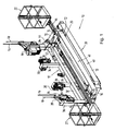
- the vehicle shown in the drawing 10 is mainly used to carry out inspection and maintenance of rotor blades and towers of wind turbines, but can also be used in inspection and maintenance of other tall structures, such as television towers or chimneys.
- the vehicle 10 consists essentially of a base body 12, which can be moved by two continuous winches 14 on two hoisting ropes 16 along a tower (not shown) of a wind turbine up and down, two safety ropes 18 to secure the vehicle 10, two foldable three-armed articulated arms 20, which at different heights at two opposite narrow sides of the base body 12 are arranged and equipped at their free end in each case with a work basket 22, two straps 24, which looped at a distance above and below the articulated arm 20 around the tower of the wind turbine and each stretched with two mounted on the base 12 winds 26 can be, and a total of four supports 30, with which the base body 12 is supported above and below the articulated arm 20 on the tower of the wind turbine.
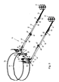
- the two foldable three-armed articulated arms 20 can each have a in Fig. 1 illustrated transport state, a in Fig. 2 shown driving state, as well as a variety of working states occupy, one of which in Fig. 3 and 4 is shown by way of example.
- transport condition Fig. 1
- the foldable articulated arms 20 are folded on a transport vehicle in such a way that they have a minimum length which is shorter than their length in the driving state (FIG. Fig. 2 ), and that in a longitudinal direction of the main body 12, only the working baskets 22 project beyond it, while the folded articulated arms abut against the broad side of the main body 12 facing away from the tower. laterally.
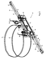
- the driving state Fig.
- the articulated arms 20 are also folded, but in a different configuration, so that they protrude longitudinally of the body 12 partially on this and the working baskets 22 in front of the far side facing away from the tower of the main body 12 are arranged.
- the center of gravity of the vehicle 10 is located in a vertical plane below the points of attack of the two hoisting ropes 16 so that essentially no moment is exerted about a longitudinal central axis of the vehicle 10 and the vehicle 10 hangs in a position on the hoisting ropes 16, in the the bottom of the work baskets 22 are aligned horizontally.
- the articulated arms 20 are pivoted outward from the base body 12, wherein the articulated arms 20 and their working baskets 22 can take a variety of different positions in which the articulated arms 20, at least when performing maintenance on a rotor blade far over that of the tower projecting away broad side of the base body 12.
- the articulated arms 20 are stretched and aligned generally perpendicular to the base body 12.
- the basic body 12 welded together from steel profiles consists essentially of a horizontal beam 32, and two inner and two outer vertical beams 34, 36 which are rigidly connected to the horizontal beam 32 and project laterally beyond the horizontal beam 32 at the lateral spacing ,
- the continuous winches 14 are mounted, with which the vehicle 10 is moved along the hoisting ropes 16 up and down.
- block stops 28 carry the upper ends of the outer vertical support 36 so-called block stops 28 through which the safety cables 18 extend.
- the two articulated arms 20 are attached.
- the two pairs of winches 26 are mounted at a vertical distance above or below the articulated arms 20, with which the straps surrounding the tower 24 can be stretched or loosened as needed.
- the two inner vertical support 34 on the tower side facing the four supports 30 are mounted in the form of two rollers with horizontal axes of rotation, with which the base body 12 is supported at strained straps 24 against the tower and in the driving state can roll on the tower surface.
- the two continuous winches 14 may, for example, be continuous winches, which are available under the name Tirak from the company Greifzug.
- the continuous winches 12 include magnetic brakes that automatically close in the event of a power failure and then prevent movement of the vehicle 10 along the hoisting ropes 16.
- the two block stops 28 lock mechanically when the vehicle 10 moves at too high speed on the safety ropes 18 down.
- the two foldable three-armed articulated arms 20 are made of fine-grained steel and each comprise a first, second and third articulated arm 40, 42, 44. Between the base body 12 and the first articulated arm 40 and between the first articulated arm 40 and the second articulated arm 42 is in each case a pivot joint 46, 48 is arranged with a vertical pivot axis, while between the second articulated arm 42 and the third articulated arm 44, a pivot joint 50 is arranged with a horizontal Schenkachse, so that the third articulated arm 44 with the work basket 22 with respect to the second articulated arm 42 up and down can be swiveled.
- a first hydraulic cylinder 52 is arranged, with which the entire articulated arm 20 can be pivoted horizontally with respect to the main body 12.
- a second hydraulic cylinder 54 is arranged, with which the second and third articulated arm 42, 44 and the working basket 20 with respect to the first articulated arm 40 can be pivoted horizontally.
- a third hydraulic cylinder 56 is arranged, with which the third articulated arm 44 and the working cage 22 with respect to the second Articulated arm 42 can be pivoted in a vertical plane.
- the cylinder tube 58 of the second hydraulic cylinder 54 is articulated on the first articulated arm 40, while the piston rod 60 is connected to both the first and the second articulated arm 40, 42 via a mechanical spreading mechanism 62.
- the spreading mechanism 62 By means of the spreading mechanism 62, the first and second articulated arms 40, 42 can be pivoted 180 degrees relative to each other.
- the third articulated arm 44 is pivotally attached to the underside of the work cage 22. How best in Fig. 4 and 9 illustrated, the third articulated arm 44 has a parallel link with two handlebars 66, which ensures during pivoting of the third articulated arm 44 that the work basket 22 maintains an orientation in which its bottom is horizontal.
- the first articulated arm 40 is composed of a first short arm part 70 which is pivotally connected to the main body 12 by the first pivot joint 46, and a second long arm part 72 pivotally connected to the first arm part 70 by a pivot pin 74 having a vertical pivot axis connected is.
- the second arm part 72 can be locked relative to the first arm part 70 by means of a locking pin 74 in two discrete pivoting positions, in which the locking pin 74 in each case passes through two bolt openings 76 in an extension 78 of the second arm part 72.
- a first pivot position ( Fig. 6 ) aligns the second arm portion 72 with the first arm portion 70, whereby the length of the articulated arm 20 can be maximized in the working states.
- the second arm part 72 In a second pivot position ( Fig. 5 ), the second arm part 72 is aligned approximately perpendicular to the first arm part 50, whereby in the transport state, the length of the folded articulated boom 20 can be shortened in order to reduce the footprint of the vehicle 20.
- the second articulated arm 42 consists of a first long arm part 80 which is pivotally connected to the first articulated arm 40 by the second pivot 48 and a second short arm part 82 on the end of the second articulated arm 42 adjacent to the third articulated arm 44 Arm member 82 is pivotally connected to first arm member 80 by a pivot pin 84 having a vertical pivot axis.
- the second arm part 82 can be locked by means of a locking bolt 86 with respect to the first arm part 80 in a first pivoting position (FIG. Fig. 8 and 9 ), in which the second arm part 82 is aligned with the first arm part 80. After removal of the locking pin 86, the second arm part 80 in a second pivot position ( Fig.
- the work basket-side end of the third articulated arm 44 of the one articulated arm 20 extends over the first short arm portion 70 of the first articulated arm 40 of the other articulated arm 20, while the working basket-side end of the third articulated arm 44 of the other articulated arm 20 is below the first short Arm portion 70 of the first articulated arm 40 of the one articulated arm 20 extends therethrough.
- the baskets 22 are in opposite directions Directions about the folded articulated arms 40, 42 over, which have been brought in the transport state in its second pivot position, in which the space or the length of the articulated arm 20 is the lowest.
- a control console (not shown) is provided in each of the two working baskets 22, which control console is connected to a control unit 20. With the control console, the hydraulic cylinder 52, 54, 56 can be controlled to bring the work basket 22 in a desired position.
- control consoles are connected in such a way that the hydraulic cylinders 52, 54, 56 of each articulated arm 20 can also be controlled by the control console in the work basket 22 of the other articulated arm 20, so that, for example, in the event of an accident involving a person in one of the two work baskets 22, his articulated arm 20 can be transferred from a person in the other work basket 22 back into the folded state of the vehicle, since the vehicle 20 can drive only in this state down.
- the control of the vehicle 20 is equipped with a safety circuit, on the one hand ensures that the two articulated arms 20 only then from the folded state of driving in a cantilevered Allow work to be transferred when the two straps 24 are tensioned and the winches 26 are locked or blocked by means of the integrated brakes.
- the safety circuit also ensures that the brakes of the two winches 26 can only be released when both articulated arms 20 are in the folded driving state.
- Each of the two straps 24, which wrap the tower vertically apart from each other, is a tear-resistant flat belt 24, the opposite ends of which are each wound on a take-up drum 84 of one of the winches 26.
- the strap 24 may be provided with a wear cover of rubber or other elastic or compliant material.
- the winches 26 each have an electric drive with a reversible direction of rotation, so that by driving the two winches 26, the belt 24 can be wound on the take-up drums 84 or unwound as needed to shorten or extend the loop length of the belt 24 to adapt them to the tower diameter at the height of the vehicle 20 or to tension the belt 24.
- Each winch 26 has an integrated brake or lock which locks the take-up drum 84 in the de-energized state of the winch 26 and prevents unwinding of the belt 24 from the drum 84 as long as no power is supplied to the winch 26.
- the upper strap 24 wraps around the tower at a vertical distance above the two articulated arms 20, while the lower strap 24 surrounds the tower slightly below the articulating arms 20. *** "
- the straps 24 serve to pull the main body 12 against the tower until the supports 30 are pressed against the tower.
- the upper belt 24 serves together with the two supports 30 arranged below the articulated arms 20 to intercept the moments exerted by the projecting articulated arms 20 in the working states on the base body 12 and to introduce them into the tower and thus prevent the working baskets 22 from swinging downwards.
- the lower belt is primarily used to prevent the vehicle 20 from rotating about an axis passing through the center of the body 12 and the tower when the moments exerted on the body by the articulated arms 20 are very different, for example because only one of the articulated arms 20 is extended.
- the supports 30 each consist of two superimposed rollers which are mounted at the top and at the bottom of the inner vertical support 34 so that they are pressed during clamping of one or both straps 24 against the base body 12 facing surface of the tower. At the same time, the rollers serve as guide rollers when the straps 24 are loosened or loosened in the driving state and the vehicle 10 is moved upwards or downwards along the hoisting ropes 16.
Landscapes
- Engineering & Computer Science (AREA)
- Architecture (AREA)
- Mechanical Engineering (AREA)
- Structural Engineering (AREA)
- Civil Engineering (AREA)
- Life Sciences & Earth Sciences (AREA)
- Sustainable Development (AREA)
- Sustainable Energy (AREA)
- Chemical & Material Sciences (AREA)
- Combustion & Propulsion (AREA)
- General Engineering & Computer Science (AREA)
- Geology (AREA)
- Jib Cranes (AREA)
Priority Applications (1)
| Application Number | Priority Date | Filing Date | Title |
|---|---|---|---|
| EP12005606.4A EP2693045A1 (fr) | 2012-08-01 | 2012-08-01 | Système de déplacement destiné à réaliser des travaux d'inspection et d'entretien sur des bâtiments de type tour |
Applications Claiming Priority (1)
| Application Number | Priority Date | Filing Date | Title |
|---|---|---|---|
| EP12005606.4A EP2693045A1 (fr) | 2012-08-01 | 2012-08-01 | Système de déplacement destiné à réaliser des travaux d'inspection et d'entretien sur des bâtiments de type tour |
Publications (1)
| Publication Number | Publication Date |
|---|---|
| EP2693045A1 true EP2693045A1 (fr) | 2014-02-05 |
Family
ID=47002477
Family Applications (1)
| Application Number | Title | Priority Date | Filing Date |
|---|---|---|---|
| EP12005606.4A Withdrawn EP2693045A1 (fr) | 2012-08-01 | 2012-08-01 | Système de déplacement destiné à réaliser des travaux d'inspection et d'entretien sur des bâtiments de type tour |
Country Status (1)
| Country | Link |
|---|---|
| EP (1) | EP2693045A1 (fr) |
Cited By (6)
| Publication number | Priority date | Publication date | Assignee | Title |
|---|---|---|---|---|
| CN106088566A (zh) * | 2016-06-03 | 2016-11-09 | 江苏科技大学 | 一种用于风电塔筒维护及施工平台的紧急保护装置 |
| CN107975460A (zh) * | 2017-12-01 | 2018-05-01 | 刘艳 | 风电机组叶片维护装置 |
| CN110998042A (zh) * | 2017-07-05 | 2020-04-10 | 安利马克集团管理公司 | 运输系统、电梯系统、套件、塔架区段和用于在塔架中执行组装或维护操作的方法 |
| WO2022112111A1 (fr) * | 2020-11-26 | 2022-06-02 | Pp Energy Aps | Agencement de guidage de tour destiné à une plateforme d'accès à une pale d'éolienne |
| WO2022112121A1 (fr) * | 2020-11-26 | 2022-06-02 | Pp Energy Aps | Agencement de guidage de tour destiné à une plateforme d'accès à une pale d'éolienne |
| CN116767073A (zh) * | 2023-08-22 | 2023-09-19 | 华能新能源股份有限公司山西分公司 | 一种风力发电机组配件装配用道路支撑运输挂车 |
Citations (12)
| Publication number | Priority date | Publication date | Assignee | Title |
|---|---|---|---|---|
| US2309769A (en) * | 1941-09-12 | 1943-02-02 | Chance Co Ab | Transformer gin |
| US4243350A (en) * | 1978-02-06 | 1981-01-06 | Hall Robert E | Winch load fastening apparatus |
| FR2702752A1 (fr) * | 1993-03-17 | 1994-09-23 | Hiviaco 88 | Dispositif élévateur pour nacelle de transport de personnes. |
| DE19647515A1 (de) * | 1996-11-16 | 1998-05-20 | Otto Gerd Albrecht | Windkonvertermontageeinrichtung |
| WO2004081373A2 (fr) | 2003-03-11 | 2004-09-23 | aeroconcept Ingenieurgesellschaft für Luftfahrttechnik und Faserverbundtechnologie mbH | Plate-forme d'entretien |
| WO2005064152A2 (fr) | 2003-12-30 | 2005-07-14 | Pp Energy Aps | Dispositif permettant l'acces a une structure surplombant le niveau du sol |
| WO2007085265A1 (fr) | 2006-01-27 | 2007-08-02 | Pp Energy Aps | Dispositif donnant acces a une structure se trouvant au-dessus du niveau du sol |
| US20090110531A1 (en) * | 2007-10-25 | 2009-04-30 | Yeary Enoch R | Elevated sports stand for the handicapped |
| US20090272709A1 (en) * | 2008-05-02 | 2009-11-05 | Nessner Thomas J | Portable pillar-mountable hoist |
| WO2010136026A2 (fr) | 2009-05-29 | 2010-12-02 | Ebf Dresden Gmbh | Dispositif destiné à des travaux d'inspection et de maintenance sur des pales de rotor et/ou sur la surface d'un mât de grandes éoliennes, en particulier d'éoliennes en haute mer |
| US8062106B1 (en) * | 2009-03-25 | 2011-11-22 | C.E. Smith Co., Inc. | Lifting holder for an animal feeder |
| EP2394947A1 (fr) | 2010-06-10 | 2011-12-14 | Special Blade Service B.V. | Plate-forme pour une turbine éolienne |
-
2012
- 2012-08-01 EP EP12005606.4A patent/EP2693045A1/fr not_active Withdrawn
Patent Citations (12)
| Publication number | Priority date | Publication date | Assignee | Title |
|---|---|---|---|---|
| US2309769A (en) * | 1941-09-12 | 1943-02-02 | Chance Co Ab | Transformer gin |
| US4243350A (en) * | 1978-02-06 | 1981-01-06 | Hall Robert E | Winch load fastening apparatus |
| FR2702752A1 (fr) * | 1993-03-17 | 1994-09-23 | Hiviaco 88 | Dispositif élévateur pour nacelle de transport de personnes. |
| DE19647515A1 (de) * | 1996-11-16 | 1998-05-20 | Otto Gerd Albrecht | Windkonvertermontageeinrichtung |
| WO2004081373A2 (fr) | 2003-03-11 | 2004-09-23 | aeroconcept Ingenieurgesellschaft für Luftfahrttechnik und Faserverbundtechnologie mbH | Plate-forme d'entretien |
| WO2005064152A2 (fr) | 2003-12-30 | 2005-07-14 | Pp Energy Aps | Dispositif permettant l'acces a une structure surplombant le niveau du sol |
| WO2007085265A1 (fr) | 2006-01-27 | 2007-08-02 | Pp Energy Aps | Dispositif donnant acces a une structure se trouvant au-dessus du niveau du sol |
| US20090110531A1 (en) * | 2007-10-25 | 2009-04-30 | Yeary Enoch R | Elevated sports stand for the handicapped |
| US20090272709A1 (en) * | 2008-05-02 | 2009-11-05 | Nessner Thomas J | Portable pillar-mountable hoist |
| US8062106B1 (en) * | 2009-03-25 | 2011-11-22 | C.E. Smith Co., Inc. | Lifting holder for an animal feeder |
| WO2010136026A2 (fr) | 2009-05-29 | 2010-12-02 | Ebf Dresden Gmbh | Dispositif destiné à des travaux d'inspection et de maintenance sur des pales de rotor et/ou sur la surface d'un mât de grandes éoliennes, en particulier d'éoliennes en haute mer |
| EP2394947A1 (fr) | 2010-06-10 | 2011-12-14 | Special Blade Service B.V. | Plate-forme pour une turbine éolienne |
Cited By (9)
| Publication number | Priority date | Publication date | Assignee | Title |
|---|---|---|---|---|
| CN106088566A (zh) * | 2016-06-03 | 2016-11-09 | 江苏科技大学 | 一种用于风电塔筒维护及施工平台的紧急保护装置 |
| CN110998042A (zh) * | 2017-07-05 | 2020-04-10 | 安利马克集团管理公司 | 运输系统、电梯系统、套件、塔架区段和用于在塔架中执行组装或维护操作的方法 |
| CN110998042B (zh) * | 2017-07-05 | 2021-06-22 | 安利马克集团管理公司 | 用于在塔架结构中执行组装或维护操作的运输系统、套件和方法 |
| CN107975460A (zh) * | 2017-12-01 | 2018-05-01 | 刘艳 | 风电机组叶片维护装置 |
| WO2022112111A1 (fr) * | 2020-11-26 | 2022-06-02 | Pp Energy Aps | Agencement de guidage de tour destiné à une plateforme d'accès à une pale d'éolienne |
| WO2022112121A1 (fr) * | 2020-11-26 | 2022-06-02 | Pp Energy Aps | Agencement de guidage de tour destiné à une plateforme d'accès à une pale d'éolienne |
| EP4251827A1 (fr) * | 2020-11-26 | 2023-10-04 | PP Energy ApS | Agencement de guidage de tour destiné à une plateforme d'accès à une pale d'éolienne |
| CN116767073A (zh) * | 2023-08-22 | 2023-09-19 | 华能新能源股份有限公司山西分公司 | 一种风力发电机组配件装配用道路支撑运输挂车 |
| CN116767073B (zh) * | 2023-08-22 | 2023-10-20 | 华能新能源股份有限公司山西分公司 | 一种风力发电机组配件装配用道路支撑运输挂车 |
Similar Documents
| Publication | Publication Date | Title |
|---|---|---|
| EP1815136B1 (fr) | Dispositif et procede pour le montage et/ou le demontage d'un composant d'une eolienne | |
| EP2364948B1 (fr) | Grue | |
| EP1666401B1 (fr) | Grue mobile | |
| DE10022658B4 (de) | Teleskopkran | |
| EP2308792B1 (fr) | Grue avec un dispositif de tension de fléche | |
| EP2693045A1 (fr) | Système de déplacement destiné à réaliser des travaux d'inspection et d'entretien sur des bâtiments de type tour | |
| DE102009005632B4 (de) | Handhabung von Rotorblättern | |
| EP2248754A1 (fr) | Grue télescopique dotée d'un dispositif d'ancrage à montage automatique et procédé de montage d'un dispositif d'ancrage | |
| EP3132137B1 (fr) | Système de grue mobile et procédé de montage temporaire dudit système de grue | |
| DE102010023275B4 (de) | Verfahren zum Verfahren von Großkranen im aufgerüsteten System und System zum Durchführen dieses Verfahrens | |
| WO2015090282A1 (fr) | Dispositif de retenue, de levage et de blocage permettant un montage sur de hauts bâtiments du type mât | |
| DE202005005627U1 (de) | Kran sowie Abspannvorrichtung hierfür | |
| DE102015009156B4 (de) | Teleskopausleger eines Krans mit Abspannung sowie Kran | |
| DE102010060639A1 (de) | Arbeitsbühnenanlage | |
| DE202005019439U1 (de) | Hebebühne | |
| DE202005016743U1 (de) | Kran | |
| DE20218971U1 (de) | Mobilkran mit langen Auslegern | |
| EP2897892B1 (fr) | Procédé permettant de faire fonctionner une grue, et grue correspondante | |
| DE20203443U1 (de) | Teleskopausleger | |
| DE20208740U1 (de) | Teleskopausleger eines Krans | |
| EP2984024B1 (fr) | Flèche de grue repliable et grue | |
| DE3401094C2 (de) | Kran mit teleskopierbarem Turm | |
| DE102019122071B3 (de) | Teleskopausleger mit ausklappbarem Mast | |
| DE102010046403B4 (de) | Verfahren zum Rangieren und Verfahren eines Fahrzeugkrans | |
| DE102009032426B3 (de) | Vorrichtung zur Montage und/oder Demontage von Ballast an einem Kran und Turmdrehkran mit einer derartigen Vorrichtung |
Legal Events
| Date | Code | Title | Description |
|---|---|---|---|
| AK | Designated contracting states |
Kind code of ref document: A1 Designated state(s): AL AT BE BG CH CY CZ DE DK EE ES FI FR GB GR HR HU IE IS IT LI LT LU LV MC MK MT NL NO PL PT RO RS SE SI SK SM TR |
|
| AX | Request for extension of the european patent |
Extension state: BA ME |
|
| PUAI | Public reference made under article 153(3) epc to a published international application that has entered the european phase |
Free format text: ORIGINAL CODE: 0009012 |
|
| STAA | Information on the status of an ep patent application or granted ep patent |
Free format text: STATUS: THE APPLICATION IS DEEMED TO BE WITHDRAWN |
|
| 18D | Application deemed to be withdrawn |
Effective date: 20140806 |