EP2897505B1 - Coffee grinder, coffee machine containing a coffee grinder and method for grinding coffee beans - Google Patents
Coffee grinder, coffee machine containing a coffee grinder and method for grinding coffee beans Download PDFInfo
- Publication number
- EP2897505B1 EP2897505B1 EP13799383.8A EP13799383A EP2897505B1 EP 2897505 B1 EP2897505 B1 EP 2897505B1 EP 13799383 A EP13799383 A EP 13799383A EP 2897505 B1 EP2897505 B1 EP 2897505B1
- Authority
- EP
- European Patent Office
- Prior art keywords
- coffee
- ground
- grinding
- grinding wheel
- grinder
- Prior art date
- Legal status (The legal status is an assumption and is not a legal conclusion. Google has not performed a legal analysis and makes no representation as to the accuracy of the status listed.)
- Active
Links
- 235000013353 coffee beverage Nutrition 0.000 title claims description 151
- 235000016213 coffee Nutrition 0.000 title claims description 150
- 241000533293 Sesbania emerus Species 0.000 title claims description 50
- 238000000034 method Methods 0.000 title description 11
- 238000001802 infusion Methods 0.000 claims description 14
- 238000004140 cleaning Methods 0.000 claims description 8
- 239000000843 powder Substances 0.000 description 9
- 230000000694 effects Effects 0.000 description 3
- 239000002245 particle Substances 0.000 description 3
- 230000005484 gravity Effects 0.000 description 2
- 238000012986 modification Methods 0.000 description 2
- 230000004048 modification Effects 0.000 description 2
- 230000003647 oxidation Effects 0.000 description 2
- 238000007254 oxidation reaction Methods 0.000 description 2
- 238000002360 preparation method Methods 0.000 description 2
- 238000009825 accumulation Methods 0.000 description 1
- 230000002411 adverse Effects 0.000 description 1
- 239000012080 ambient air Substances 0.000 description 1
- 235000013361 beverage Nutrition 0.000 description 1
- 230000015572 biosynthetic process Effects 0.000 description 1
- 206010006514 bruxism Diseases 0.000 description 1
- 235000015116 cappuccino Nutrition 0.000 description 1
- 230000015556 catabolic process Effects 0.000 description 1
- 238000004891 communication Methods 0.000 description 1
- 238000010276 construction Methods 0.000 description 1
- 238000006731 degradation reaction Methods 0.000 description 1
- 238000013461 design Methods 0.000 description 1
- 238000006073 displacement reaction Methods 0.000 description 1
- 235000015114 espresso Nutrition 0.000 description 1
- 238000009434 installation Methods 0.000 description 1
- 230000002093 peripheral effect Effects 0.000 description 1
- 230000001131 transforming effect Effects 0.000 description 1
- 238000011144 upstream manufacturing Methods 0.000 description 1
Images


Classifications
-
- A—HUMAN NECESSITIES
- A47—FURNITURE; DOMESTIC ARTICLES OR APPLIANCES; COFFEE MILLS; SPICE MILLS; SUCTION CLEANERS IN GENERAL
- A47J—KITCHEN EQUIPMENT; COFFEE MILLS; SPICE MILLS; APPARATUS FOR MAKING BEVERAGES
- A47J31/00—Apparatus for making beverages
- A47J31/42—Beverage-making apparatus with incorporated grinding or roasting means for coffee
-
- A—HUMAN NECESSITIES
- A47—FURNITURE; DOMESTIC ARTICLES OR APPLIANCES; COFFEE MILLS; SPICE MILLS; SUCTION CLEANERS IN GENERAL
- A47J—KITCHEN EQUIPMENT; COFFEE MILLS; SPICE MILLS; APPARATUS FOR MAKING BEVERAGES
- A47J42/00—Coffee mills; Spice mills
- A47J42/12—Coffee mills; Spice mills having grinding discs
- A47J42/16—Coffee mills; Spice mills having grinding discs mechanically driven
-
- A—HUMAN NECESSITIES
- A47—FURNITURE; DOMESTIC ARTICLES OR APPLIANCES; COFFEE MILLS; SPICE MILLS; SUCTION CLEANERS IN GENERAL
- A47J—KITCHEN EQUIPMENT; COFFEE MILLS; SPICE MILLS; APPARATUS FOR MAKING BEVERAGES
- A47J42/00—Coffee mills; Spice mills
- A47J42/38—Parts or details
- A47J42/40—Parts or details relating to discharge, receiving container or the like; Bag clamps, e.g. with means for actuating electric switches
Definitions
- the present disclosure relates to coffee beans grinders, in particular for installation in automatic or semi-automatic coffee machines and the like.
- the disclosure further refers to a coffee machine including such a coffee-beans grinder.
- Some coffee makers are provided with a coffee grinder for grinding coffee beans dispensed from a coffee beans container to produce ground coffee.
- the ground coffee in powder form is then loaded in an infusion unit for the preparation of a coffee-based beverage, e.g. espresso, cappuccino, filter coffee, or the like.
- a coffee-based beverage e.g. espresso, cappuccino, filter coffee, or the like.
- Coffee grinders for coffee machines are usually comprised of a first, stationary grinding wheel and a second, rotary grinding wheel.
- the grinding wheels are arranged one facing the other in order to define a grinding volume there between.
- the two oppositely arranged grinding wheels are usually provided with broadly conical grinding surfaces provided with grinding teeth.
- the grinding wheels are usually arranged one on top of the other and an aperture in the upper grinding wheel is provided, for introducing coffee beans into the grinding space or grinding volume defined between the two grinding wheels.
- the rotation of one grinding wheel with respect to the other crushes the coffee beans producing ground coffee, which is collected in a radially extending outlet channel.
- the ground coffee is slightly compacted in the outlet channel before being discharged in a ground coffee chute, which dispenses the ground coffee directly into the infusion unit arranged underneath the ground coffee chute.
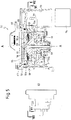
- FIG. 1 illustrates a section along the rotation axis of the rotary grinding wheel.
- Fig.2 illustrates a section according to line II-II of Fig. 1 .
- Reference number 1 indicates the coffee grinder as a whole.
- the coffee grinder 1 comprises a stationary bearing or supporting structure 3, intended to be mounted in a coffee machine.
- the structure 3 forms a seat 5 housing a first, upper grinding wheel 7 and a second, lower grinding wheel 9.
- the first grinding wheel 7 is stationary, while the second, lower grinding wheel 9 is a rotary grinding wheel and can be driven into rotation around a rotation axis A-A by means of an electric motor 11, through a gear 13 mounted on a shaft 15.
- An auger 17 is also mounted on the shaft 15, to feed coffee beans into the grinding volume 19 formed between the opposite grinding surfaces of the first, stationary grinding wheel 7 and the second, rotary grinding wheel 9.
- An aperture 27 in the upper, stationary grinding wheel 7 allows the coffee beans to enter the grinding volume 19.
- Ground coffee exiting the grinding volume 19 is collected in an outlet channel 21.
- the outlet channel 21 extends radially from the seat 5, where the grinding wheels 7 and 9 are housed, towards a ground coffee chute.
- An elastic flap 23 is arranged across the outlet channel 21, so that the ground coffee delivered by the grinding wheels 7, 9 housed in seat 5 is slightly compacted while advancing along the outlet channel 21.
- the outlet channel 21 ends into a ground coffee chute 23 which is downwardly oriented so as to load the ground coffee into an infusion unit schematically shown at 25 and arranged under the ground coffee chute 23.
- coffee beans are usually fed from the top into the central aperture 27 and the coffee beans are caused to advance by gravity and by the rotation of the auger 17, while the grinder 1 is powered.
- the ground coffee is collected in the outlet channel 21 and fills said channel up to the edge 21A at the end of the channel from where the ground coffee falls by gravity into the coffee chute 23.
- the grinder 1 is de-energized, the lower, rotary grinding wheel 9 stops and the already ground coffee filling the grinding volume 19 and the outlet channel 29 remains in the grinder 1 until the subsequent grinding cycle starts.
- a grinder of this kind is disclosed for example in US-A-2010/0037778 .
- the quality of the first coffee cup brewed upon resumption of the machine operation can be negatively affected by oxidation of the ground coffee, which took place overnight. The longer the period during which the grinder remains inoperative, the heavier the degradation of the ground coffee.
- the user desires to change the quality of the coffee beans used, for example replacing regular coffee with decaffeinated coffee, at least the first coffee cup dispensed by the coffee machine will be prepared at least partly with the old coffee quality previously contained in the coffee container, since ground coffee produced by grinding the old coffee quality previously present in the machine is still contained in the grinding volume 19 and in the outlet channel 21.
- a coffee grinder according to claim 1 To remove or at least alleviate at least one of the problems arising from the use of the prior art grinders, a coffee grinder according to claim 1, a coffee machine according to claim 9.
- the method for grinding coffee beans in a coffee machine comprises the steps of:
- the grinding wheels are kept in relative rotary movement for a time sufficient to crush all the coffee beans delivered in the grinding volume, thus entirely transforming the coffee beans into coffee powder, and to remove by centrifugal force the ground coffee from the grinding volume between the grinding wheels and from the seat where the grinding wheels are arranged.
- This grinding process results in the grinder remaining substantially free of coffee residues. If the coffee machine and the grinder remain inactive for a relatively long period of time, e.g. overnight, the next grinding and infusion cycles performed after the period of non-use of the machine will be carried out using fresh coffee beans and substantially no (or a negligible amount of) oxidized or partly oxidized or deteriorated ground coffee from previous grinding cycles will adversely affect the taste of the coffee beverage.
- the side surface of the ground-coffee outlet opening is oriented to facilitate projection of ground coffee from the grinding volume and from the seat by effect of centrifugal force into a ground-coffee chute.
- Mutual rotation of the first and second grinding wheels is controlled so that once the coffee beans fed to the grinding wheel are exhausted, rotation is continued to clean the grinding volume and the seat of the grinding wheels, thus removing residual ground coffee by centrifugal force.
- the first cup of coffee brewed with the new coffee quality will contain substantially no residues, or only negligible residues, of the previously used quality.
- EP2364624 discloses a coffee grinder according to the pre-amble of claim 1.
- the method can comprise the following steps: feeding a metered amount of coffee beans in the grinding volume; rotating the first grinding wheel and the second grinding wheel one with respect to the other to grind said metered amount of coffee beans; continuing rotation to remove ground coffee from said seat and said grinding volume by centrifugal force.
- Rotation of the grinding wheel(s) can stop after a pre-determined time interval, which is calculated such that the maximum possible metered amount of coffee will be completely ground and the ground coffee will be removed from the grinder. Since the amount of coffee beans used for a grinding cycle and an infusion cycle is determined by the amount of ground coffee required for the infusion of one or two coffee cups, the pre-set time interval can be calculated so that the number of revolutions performed by the rotating grinding wheel is sufficient to grind twice the maximum amount of coffee beans usable for the preparation of a cup of coffee. This amount is set by the mechanical features of the infusion unit. An extra grinding time can be added, to allow the grinder rotating under no-load conditions, to ensure that residues of ground coffee are properly removed from the grinding volume and the seat of the grinding wheels.
- Means are provided to detect the actual exhaustion of the coffee beans in the grinding volume.
- the rotary motion of the grinder can then be maintained for a certain amount of extra-time following the detected exhaustion of the coffee beans.
- a coffee-beans metering device can be arranged above the coffee grinder.
- substantially tangent shall be understood to be an orientation which is exactly or nearly tangent to the cylindrical wall, such that the ground coffee will be easily projected out of the seat where the grinding wheels are arranged.
- substantially tangent means that the side surface forms an angle between -10° and +40° with the tangent direction and preferably between -5° and +20° and even more preferably between -5° and +10°.
- the side surface is tangent to the cylindrical surface of the grinding wheels seat.
- the tangent or substantially tangent orientation of the side surface is such that the speed vector of the ground coffee projecting from the grinding volume due to centrifugal force is oriented concordant or approximately concordant to the orientation of the side surface. This assists ejection of the ground coffee from the grinding volume and from the seat of the grinding wheels, making cleaning of the grinder easier and more effective.
- the ground-coffee outlet opening through which the ground coffee exits from the grinder is thus oriented in a non-radial direction.
- the side surface ends into said ground-coffee chute.
- the length of the side surface is kept to a minimum value, consistently with the mechanical and design constraints. This avoids or reduces the formation of dead volumes where the ground coffee expelled from the grinding volume could accumulate.
- the ground-coffee chute has a circular or nearly circular cross-section.
- an impact shield is arranged in the ground-coffee chute in front of the ground-coffee outlet.
- the impact shield has a substantially planar impact surface facing said ground-coffee outlet opening and can be advantageously orthogonal or substantially orthogonal to the side surface of the ground-coffee outlet opening. The speed direction of the ground coffee impinging against the impact shield will therefore be approximately at 90° with respect to the impact surface. This arrangement minimizes the tendency of the coffee powder to adhere on the impact surface and accumulate thereon.
- the rotating grinding wheel can be provided with radial projections configured and arranged for removing ground coffee collecting in the seat, between the cylindrical wall of said seat and the grinding wheels.
- the rotating projections move the ground coffee along the cylindrical surface until the ground coffee escapes through the ground-coffee outlet opening provided along the cylindrical seat.
- a coffee machine comprising a coffee grinder as described above and an infusion unit arranged underneath said coffee grinder.
- EP2364624 discloses a coffee grinder according to the pre-amble of claim 1.
- Features and embodiments are disclosed here below and are further set forth in the appended claims, which form an integral part of the present description.
- the above brief description sets forth features of the various embodiments of the present invention in order that the detailed description that follows may be better understood and in order that the present contributions to the art may be better appreciated.
- the various embodiments of the invention are not limited in their application to the details of the construction and to the arrangements of the components set forth in the following description or illustrated in the drawings.
- the invention is capable of other embodiments and of being practiced and carried out in various ways. Also, it is to be understood that the phraseology and terminology employed herein are for the purpose of description and should not be regarded as limiting.
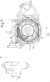
- Figs. 3 to 7 illustrate an exemplary embodiment of a grinder according to the present disclosure.
- the grinder is labeled 50 as a whole and comprises a stationary bearing structure 51 defining a seat 53 housing a first grinding wheel 55 and a second grinding wheel 57.
- the first grinding wheel 55 is positioned above the second grinding wheel 57.
- the grinding wheels will therefore be referred to here below also as “the upper” grinding wheel 55 and "the lower” grinding wheel 57.
- the grinder 50 can be housed in a coffee machine, e.g. an automatic coffee machine.
- Fig.9 illustrates a schematic side view of a coffee machine 30 provided with a coffee grinder 50.
- the coffee machine 30 has a housing 31 and is provided with a coffee-bean container 32.
- An infusion unit, schematically shown at 74, is arranged under the coffee grinder 50.
- the coffee machine 30 is further provided with a dispensing spout 33 and a drip tray 34 positioned under the dispensing spout and provided with a grid 35 on which a container, such as a cup C can be placed for collecting coffee dispensed by the dispensing spout 33.
- the first, upper grinding wheel 55 is supported stationarily in the seat 53.
- the second, lower grinding wheel 57 is rotatingly mounted in seat 53.
- the grinding wheel 57 is constrained to a rotating shaft 59.
- the rotating shaft 59 can be integrally formed with the outer portion of the grinding wheel 57, as shown in Fig.5 .
- the rotating shaft 59 extends across an aperture provided in the bottom of the seat 53 and is supported by a bearing 59A ( Fig.5 ).
- the rotating shaft 59 is torsionally constrained to a gear 61, e.g. by means of a splined profile.
- An electric motor 63 drives into rotation the gear 61 and the grinding wheel 57, for example through a worm housed in a sleeve 65 ( Fig. 3 ) and not shown.
- the axial distance between the grinding wheels 55 and 57 can be adjustable, e.g. to meet the consumer's needs.
- the first, upper grinding wheel 55 can be axially movable with respect to the bearing structure 51 and have an adjustable axial distance from the second, lower grinding wheel 57. This can be obtained for example providing the upper grinding wheel with a male thread 65 engaging into a female thread 67, which can be integrally formed with, or constrained to the stationary bearing structure 51.
- the upper grinding wheel 55 is constrained to a toothed sector 69 (see in particular Figs. 3 and 4 ). Rotating the sector 69 around axis A-A, the first, stationary upper grinding wheels 55 can be rotated with respect to the stationary bearing structure 51.
- the threads 65 and 67 cause an axial displacement of the stationary, upper grinding wheel 55 with respect to the lower, rotary grinding wheel 57, thus adjusting the dimension of the ground coffee produced by the grinder 50.
- the seat 53 is surrounded by a substantially cylindrical inner surface 53A having a diameter corresponding to or slightly larger than the diameter of the lower, rotary grinding wheel 57.
- the inner surface 53A can have a non-cylindrical shape, e.g. a frusto-concical shape, depending upon the peripheral shape of the grinding wheels.
- the cross section of the surface 53A is however circular.
- the inner cylindrical surface 53A surrounds almost entirely the grinding wheels 55, 57, but is interrupted at a ground-coffee outlet 71, which is in communication with a ground-coffee chute 73.
- the ground-coffee chute 73 extends downwardly towards an infusion unit shown schematically at 74 in Fig. 5 .
- the substantially cylindrical surface 53A ends at 53B and merges with a side surface 75, which extends from 53B in a substantially tangential direction towards the ground-coffee chute 73.
- the surface 75 forms a continuation of the substantially cylindrical inner surface 53A of the seat 53.
- the side surface 75 ends at an edge 73A of the ground-coffee chute 73.
- the orientation of the surface 75 is concordant with the rotary speed of the second, lower grinding wheel 57, which rotates according to arrow f57 (see Figs. 6 and 7 ), i.e. in a counter-clockwise direction in the drawings.
- the side surface 75 is oriented parallel to the speed vector of the outer periphery of the rotary grinding wheel 57 at 53B.
- the orientation of the side surface 75 can be nearly tangent or substantially tangent to the cylindrical surface 53A of the seat 53 in point 53B.
- the side surface 75 could form a positive angle with respect to the tangent direction, being more open than the one depicted in the drawings. In Fig.6 this would mean a side surface 75 forming a larger angle with the vertical direction than the one shown in Fig.6 .
- the side surface 75 could form a negative angle, i.e. it could be closer to the cylindrical surface 53A and closer to a vertical direction in Fig.6 , although this would be less advantageously since projection of the coffee out of the seat 53 would be less easy.
- the wall forming the inner cylindrical surface 53 forms an edge 77, which is substantially parallel to the surface 75, so that the ground-coffee outlet 71 is delimited on both sides by two substantially rectilinear surfaces which extend parallel to one another in the direction of the speed vector of the periphery of grinding wheel 57 in the point 53B where the inner cylindrical surface 53B merges with surface 75.
- a ground-coffee outlet 71 is thus obtained, which is oriented in a non-radial direction. More specifically the ground-coffee outlet 71 is oriented according to the direction of the speed of the ground-coffee particles projecting by centrifugal force from of the grinding volume 56 formed between the first, stationary grinding wheel 55 and the second, rotary grinding wheel 57. In actual fact, the ground-coffee particles exit the slit between the two grinding wheels 55, 57 with a speed vector having a tangential component and a radial component. The tangential component of the speed of said ground-coffee particles in point 53B is substantially parallel to the surface 75. The ground-coffee outlet 71 is thus oriented so as to facilitate the projection of the ground-coffee powder out of the grinding volume 56 through the ground-coffee aperture 71 into the ground-coffee chute 73.
- agitator or stirrer 81 is mounted on shaft 59 for rotation along with the second, lower grinding wheel 57 under the control of motor 63. The agitator 81 facilitates feeding of the coffee beans into the grinding volume 56.
- a metering device schematically shown at 83 in Fig. 9 , is provided to dispense a metered quantity of coffee beans to the grinder 50.
- the metering device is arranged upstream of the grinder 50. The amount of coffee ground for each grinding cycle is therefore metered before grinding.
- the location of the metering device 83 shown in Fig.9 is schematic and exemplary. Other locations for the metering device are possible.
- the metering device 83 can entirely or partly be located inside the coffee-beans container 32. Important is only that the coffee grinder 50 receives a limited, metered amount of coffee beans.
- the electric motor 63 When the user starts a brewing cycle or an infusion cycle, the electric motor 63 is energized and the lower, rotary grinding wheel 57 starts rotating along with the agitator 81, causing the metered coffee beans to enter the grinding volume 56.
- the two grinding wheels 55 and 57 crash the coffee beans and transform them into ground coffee in powdery form, which is ejected out of the grinding volume 56 and of the seat 53 through the ground-coffee outlet 71, the orientation of which facilitates the projection of the ground coffee into the ground-coffee chute 73.
- the motor 63 is de-energized and the rotation of the lower grinding wheels 57 is stopped when the metered amount of coffee beans dispensed to the grinder 50 has been entirely crashed and ground into powder coffee, and the ground coffee has been entirely expelled through the ground coffee outlet 71.
- This can be achieved by setting a sufficiently long grinding time, so that the entire dose of metered coffee beans will be completely ground once the grinding time has elapsed. Since the amount of coffee to prepare a coffee cup is known and varies only slightly around a given value of approximately 8 g, setting the grinding time is relatively easy.
- the grinding time can be set to a value which is sufficiently higher than the time strictly required to actually grind the maximum possible amount of coffee beans metered for one grinding cycle.
- a cleaning step is performed at the end of each grinding process. During the cleaning step the second, lower grinding wheel 57 will rotate with virtually no coffee beans in the grinding volume 56. Continued rotation during this extra-time ensures that residues of crashed coffee beans or coffee powder will be expelled by centrifugal force through the non-radially oriented ground-coffee outlet 71.
- the duration of the grinding process can be set in terms of number of revolutions of the rotary grinding wheel.
- the number extra revolutions can be added to the number of revolutions required to grind the metered coffee beans, to achieve the above mentioned cleaning effect.
- the grinding time or the number of revolutions can be determined each time based on the actually metered quantity of coffee beans. For example, if the infusion unit allows to prepare more than one cup of coffee at a time, the user can set the number of coffee cups, e.g. 1 or 2 cups, and an electronic control unit can determine the grinding time or the number of revolutions required to entirely grind the metered amount of coffee beans and to clean the grinder.
- means can be adopted to detect the actual exhaustion of the coffee in the coffee grinder 50.
- the noise or the vibrations produced by the grinder can be detected, or the power absorbed by the electric motor 63 can be measured. These parameters change as the torque required to rotate the rotary grinding wheel drops due to completion of the grinding process.
- the information thus obtained can be used by a control unit, to stop the grinder after a sufficient extra rotation time or extra number of turns of the grinding wheel, to perform cleaning of the grinder.
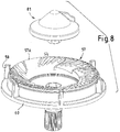
- the second, rotary grinding wheel 57 is provided with radially extending projections 58 (see in particular Figs. 6 and 8 ).
- the projections 58 extend radially to an extent sufficient to almost touch or brush the inner cylindrical surface 53A of the seat 53.
- the radial projections 58 operate as scrapers along the circumference of the seat 53 to remove any coffee powder residues from the inner surface 53A and force them to escape by centrifugal force through the ground-coffee outlet 71.
- the radial projections 58 extend axially from a shoulder 60 beyond the upper edge 57A ( Fig. 8 ) of the lower rotary grinding wheel 57. In this manner the radial projections 58 span across the slit formed between the upper, stationary grinding wheel 55 and the lower rotary grinding wheel 57, the ground coffee powder being projected out of the grinding volume 56 through said slit.
- the axial dimension of radial projections 58 is therefore sufficient to remove coffee residues deposited along the inner cylindrical surface 53A of the seat 53 along and in front of the slit between the two grinding wheels 55 and 57.
- the ground coffee chute 73 has a substantially cylindrical or conical shape and can have an approximately almost circular cross-section. This shape provides for an improved distribution of the ground coffee in the infusion unit 74.
- the width of the ground coffee chute 73 is therefore such that the inner surface thereof opposing the ground-coffee outlet 71 is set at a certain distance therefrom.
- Ground coffee projecting by centrifugal force from the seat 53 into the ground -coffee chute 73 would tend to adhere to the inner surface of the ground-coffee chute 73, opposite the ground-coffee outlet 71, mainly due to electrostatic charges and limited kinetic energy of the ground coffee reaching the inner surface of the ground-coffee chute. Most of the kinetic energy of the ground coffee is dissipated along the path traveled by the coffee powder from the grinding wheels to the inner surface of the ground-coffee chute.
- an impact shield 91 is arranged inside the ground-coffee chute 73.
- the impact shield 91 is substantially planar and has a front planar surface 91A facing the ground-coffee outlet 71.
- the planar surface 91A is oriented substantially orthogonal to the surface 75.
- the impact shield 91 is arranged at a distance from the ground-coffee outlet 71, which is substantially smaller than the distance between said ground-coffee outlet 71 and the substantially cylindrical surface of the ground-coffee chute 73 opposite the ground-coffee outlet 71. Therefore the ground coffee striking against the impact surface 91A of the impact shield 91 has a higher kinetic energy than that which the ground coffee would have if it were to directly impact against the opposing inner surface portion of the ground-coffee chute 73. The higher kinetic energy of the ground coffee impinging against the impact surface 91A reduces the amount of ground coffee, which tends to stick on said surface 91A by effect of mechanical or electrostatic forces.
Landscapes
- Engineering & Computer Science (AREA)
- Food Science & Technology (AREA)
- Mechanical Engineering (AREA)
- Apparatus For Making Beverages (AREA)
- Tea And Coffee (AREA)
Priority Applications (2)
| Application Number | Priority Date | Filing Date | Title |
|---|---|---|---|
| PL13799383T PL2897505T3 (pl) | 2012-09-21 | 2013-09-20 | Młynek do kawy, maszyna do kawy zawierająca młynek do kawy, oraz sposób mielenia ziaren kawy |
| EP13799383.8A EP2897505B1 (en) | 2012-09-21 | 2013-09-20 | Coffee grinder, coffee machine containing a coffee grinder and method for grinding coffee beans |
Applications Claiming Priority (3)
| Application Number | Priority Date | Filing Date | Title |
|---|---|---|---|
| EP12185368 | 2012-09-21 | ||
| PCT/IB2013/058688 WO2014045230A1 (en) | 2012-09-21 | 2013-09-20 | Coffee grinder and coffee machine containing a coffee grinder |
| EP13799383.8A EP2897505B1 (en) | 2012-09-21 | 2013-09-20 | Coffee grinder, coffee machine containing a coffee grinder and method for grinding coffee beans |
Publications (2)
| Publication Number | Publication Date |
|---|---|
| EP2897505A1 EP2897505A1 (en) | 2015-07-29 |
| EP2897505B1 true EP2897505B1 (en) | 2017-07-26 |
Family
ID=46970056
Family Applications (1)
| Application Number | Title | Priority Date | Filing Date |
|---|---|---|---|
| EP13799383.8A Active EP2897505B1 (en) | 2012-09-21 | 2013-09-20 | Coffee grinder, coffee machine containing a coffee grinder and method for grinding coffee beans |
Country Status (11)
| Country | Link |
|---|---|
| US (1) | US10016087B2 (ru) |
| EP (1) | EP2897505B1 (ru) |
| JP (1) | JP6328119B2 (ru) |
| CN (1) | CN104812278B (ru) |
| AU (1) | AU2013319825B2 (ru) |
| BR (1) | BR112015006000A2 (ru) |
| CA (1) | CA2885945A1 (ru) |
| MX (1) | MX356845B (ru) |
| PL (1) | PL2897505T3 (ru) |
| RU (1) | RU2647822C2 (ru) |
| WO (1) | WO2014045230A1 (ru) |
Families Citing this family (14)
| Publication number | Priority date | Publication date | Assignee | Title |
|---|---|---|---|---|
| WO2015169398A1 (en) * | 2014-05-07 | 2015-11-12 | Procaffe' S.P.A. | Automatic machine for preparing coffee |
| EP3250096B1 (en) * | 2015-01-28 | 2020-07-29 | Sanremo Coffee Machines SRL | Device for grinding coffee beans |
| CN106913217A (zh) * | 2015-12-24 | 2017-07-04 | 威斯达电器(中山)制造有限公司 | 磨豆装置及具有该磨豆装置的自动咖啡壶 |
| CN106913218A (zh) * | 2015-12-24 | 2017-07-04 | 威斯达电器(中山)制造有限公司 | 磨豆机构及具有该磨豆机构的自动咖啡壶 |
| ITUA20162938A1 (it) * | 2016-04-27 | 2017-10-27 | Gruppo Cimbali Spa | Dispositivo per conferire uniformità al flusso di caffè macinato proveniente da un macinadosatore del tipo a richiesta e diretto verso il porta filtro di una macchina per caffè espresso. |
| CN107811512B (zh) * | 2016-09-14 | 2020-05-08 | 广东美的生活电器制造有限公司 | 用磨豆咖啡机制作咖啡的方法和磨豆咖啡机 |
| JP6823447B2 (ja) * | 2016-12-15 | 2021-02-03 | ツインバード工業株式会社 | ミル刃及びミル装置 |
| IT201700058749A1 (it) * | 2017-05-30 | 2018-11-30 | De Longhi Appliances Srl | Macchina da caffè munita di macinino e procedimento per il controllo del macinino della macchina da caffè |
| CN207791202U (zh) * | 2017-07-28 | 2018-08-31 | 遨想科创有限公司 | 一种自动磨粉咖啡胶囊制造机 |
| IT201800004111A1 (it) * | 2018-03-30 | 2019-09-30 | Girardi S R L | Apparato e metodo di macinazione |
| IT201900014904A1 (it) * | 2019-08-21 | 2021-02-21 | Drm S R L | Anticlumping caffè macinato |
| DE102021205777B4 (de) | 2021-06-08 | 2024-05-16 | BSH Hausgeräte GmbH | Haushaltsgerät mit einem Mahlgutbehälter und einem Mahlwerk |
| GB202109452D0 (en) * | 2021-06-30 | 2021-08-11 | Nicholson Design Consultants Ltd | A bean grinding apparatus |
| CN115868823A (zh) * | 2021-08-18 | 2023-03-31 | 苏州咖乐美咖啡机科技有限公司 | 研磨装置 |
Family Cites Families (43)
| Publication number | Priority date | Publication date | Assignee | Title |
|---|---|---|---|---|
| US1502675A (en) * | 1923-01-10 | 1924-07-29 | Hobart Mfg Co | Grinder for coffee and the like |
| US2229031A (en) * | 1937-12-28 | 1941-01-21 | Standard Computing Scale Compa | Coffee grinder |
| US2290747A (en) * | 1939-11-02 | 1942-07-21 | Enterprise Mfg Co | Spout construction for coffee mills and the like |
| US2852203A (en) * | 1953-11-13 | 1958-09-16 | Ditting | Adjustable grinding disc |
| US2852202A (en) * | 1954-04-28 | 1958-09-16 | Ditting | Coffee grinder |
| CH322964A (de) * | 1954-04-28 | 1957-07-15 | Ditting Adolf | Einrichtung an einer Kaffeemühle mit Mahlscheiben zum Abführen des Kaffeepulvers von den Mahlscheiben in einen Sack. |
| CH322974A (fr) | 1955-02-07 | 1957-07-15 | Prod Ind S A | Installation d'électrolyse. |
| US3327615A (en) * | 1965-01-04 | 1967-06-27 | William S Swan | Coffee dispenser with built-in grinder |
| JPS49131385U (ru) * | 1973-03-16 | 1974-11-12 | ||
| JPS5967141U (ja) * | 1982-10-28 | 1984-05-07 | 三菱電機株式会社 | コ−ヒ−メ−カ− |
| JPS61194595A (ja) * | 1985-02-22 | 1986-08-28 | 東芝機器株式会社 | ミル付コ−ヒ抽出装置 |
| JPS63135113A (ja) * | 1986-11-27 | 1988-06-07 | 松下電器産業株式会社 | コ−ヒ−メ−カ− |
| JPS63270014A (ja) * | 1987-04-28 | 1988-11-08 | 松下電器産業株式会社 | 電気コ−ヒ−沸し器 |
| US5158793A (en) * | 1988-07-12 | 1992-10-27 | Edward Helbling | Coffee machine with product selectivity |
| US5186399A (en) | 1988-08-01 | 1993-02-16 | Bunn-O-Matic Corporation | Digital control system for a coffee grinder and associated coffee brewer |
| US5322005A (en) * | 1988-09-02 | 1994-06-21 | Nichimen Corporation | High capacity coffee maker with improved filtration |
| US4913037A (en) * | 1989-06-06 | 1990-04-03 | Grindmaster Corporation | Moisture protection system for the particulate food delivery apparatus of beverage preparing means |
| FR2671960B1 (fr) * | 1991-01-25 | 1993-10-15 | Moulinex | Machine a cafe automatique. |
| JPH05161552A (ja) * | 1991-12-11 | 1993-06-29 | Kazuo Enomoto | コーヒーメーカ |
| IT1263828B (it) * | 1993-01-27 | 1996-09-03 | Cimbali Spa | Macchina automatica per caffe' in bevanda,erogabile da solo o, combinato con latte,in forma di cappuccino |
| US5285705A (en) * | 1993-04-06 | 1994-02-15 | Grindmaster Corporation | Continuous acting moisture prevention and cleaning valve |
| US5865095A (en) * | 1997-03-20 | 1999-02-02 | Conair Corporation | Coffee grinder and maker |
| IT1311698B1 (it) * | 1999-07-13 | 2002-03-19 | Rolland Guy | Macchina di distribuzione e confezionamento di caffe' |
| US6783089B2 (en) | 1999-09-17 | 2004-08-31 | Food Equipment Technologies Company, Inc. | Food ingredient grinder assembly and method |
| DE29917566U1 (de) * | 1999-09-23 | 1999-12-16 | Stawert Muehlenbau Gmbh & Co K | Mühle für rieselfähiges Mahlgut, insbesondere Kaffee |
| US6511006B1 (en) * | 2001-07-16 | 2003-01-28 | Chef'n Corporation | Condiment grinder residue catch |
| US6988444B1 (en) * | 2002-05-15 | 2006-01-24 | Grindmaster Corporation | Combination grinder and brewer |
| EP1622492B1 (en) * | 2003-04-23 | 2008-10-15 | Bunn-O-Matic Corporation | Removable hopper grinder |
| EP1707089B1 (de) * | 2005-03-29 | 2007-05-02 | Saeco IPR Limited | Verfahren zum Detektieren des Fehlens von Kaffeebohnen in einem Mahlwerk einer Kaffeemaschine sowie Kaffeemaschine zur Durchführung des Verfahrens |
| WO2007027206A2 (en) * | 2005-04-11 | 2007-03-08 | Coffee Equipment Company | Machine for brewing a beverage such as coffee and related method |
| US20140060336A1 (en) * | 2006-02-23 | 2014-03-06 | Carl Campetella | Apparatus for Making Crema Coffee |
| US7252033B1 (en) * | 2006-03-14 | 2007-08-07 | Uni-Splendor Corp | Automatic coffee maker |
| US20100288777A1 (en) * | 2006-03-23 | 2010-11-18 | Breville Pty Limited | Filter Coffee Maker |
| ITFI20060281A1 (it) * | 2006-11-14 | 2008-05-15 | Saeco Ipr Ltd | Organi di macinazione per un dispositivo macina caffe' ed una macchina da caffe' comprendente tale dispositivo. |
| US20090031900A1 (en) * | 2007-06-12 | 2009-02-05 | Barraclough James R | Coffee maker |
| FR2956303B3 (fr) | 2010-02-17 | 2012-10-05 | Sara Lee / De N V | Systeme de preparation pour boisson au cafe, cartouche de conditionnement de cafe moulu pour une utilisation avec un tel systeme, procede de preparation d'une boisson au moyen dudit systeme, et procede de fourniture de cafe moulu a partir de ladite cartouche de conditionnement de cafe moulu |
| DE102010017721A1 (de) * | 2010-07-05 | 2010-12-30 | SEVERIN ELEKTROGERÄTE GmbH | Mahlwerk |
| JP5765113B2 (ja) * | 2010-07-30 | 2015-08-19 | 富士電機株式会社 | 飲料抽出用原料の粉砕装置 |
| PL2510845T3 (pl) * | 2011-04-11 | 2013-09-30 | Drogheria E Alimentari S P A | Urządzenie do mielenia |
| US9510710B1 (en) * | 2011-07-15 | 2016-12-06 | Food Equipment Technologies Company, Inc. | Food grinder with automatic off controller and method |
| US9446361B2 (en) * | 2011-10-11 | 2016-09-20 | Modern Process Equipment, Inc. | Method of densifying coffee |
| US20130091802A1 (en) * | 2011-10-14 | 2013-04-18 | Jonathan Bentley | Coffee filter pouch maker |
| US20130233176A1 (en) * | 2012-03-09 | 2013-09-12 | Yu-Yuan Lin | Coffee Maker Capable of Stopping Returning Steam |
-
2013
- 2013-09-20 PL PL13799383T patent/PL2897505T3/pl unknown
- 2013-09-20 JP JP2015532557A patent/JP6328119B2/ja not_active Expired - Fee Related
- 2013-09-20 CA CA 2885945 patent/CA2885945A1/en not_active Abandoned
- 2013-09-20 WO PCT/IB2013/058688 patent/WO2014045230A1/en active Application Filing
- 2013-09-20 BR BR112015006000A patent/BR112015006000A2/pt active Search and Examination
- 2013-09-20 CN CN201380049384.XA patent/CN104812278B/zh active Active
- 2013-09-20 AU AU2013319825A patent/AU2013319825B2/en not_active Ceased
- 2013-09-20 EP EP13799383.8A patent/EP2897505B1/en active Active
- 2013-09-20 MX MX2015003399A patent/MX356845B/es active IP Right Grant
- 2013-09-20 US US14/429,188 patent/US10016087B2/en active Active
- 2013-09-20 RU RU2015114712A patent/RU2647822C2/ru active
Also Published As
| Publication number | Publication date |
|---|---|
| MX2015003399A (es) | 2015-06-05 |
| AU2013319825B2 (en) | 2018-07-19 |
| PL2897505T3 (pl) | 2018-03-30 |
| US20150238040A1 (en) | 2015-08-27 |
| US10016087B2 (en) | 2018-07-10 |
| BR112015006000A2 (pt) | 2017-07-04 |
| RU2647822C2 (ru) | 2018-03-19 |
| EP2897505A1 (en) | 2015-07-29 |
| RU2015114712A (ru) | 2016-11-10 |
| AU2013319825A1 (en) | 2015-05-07 |
| CA2885945A1 (en) | 2014-03-27 |
| WO2014045230A1 (en) | 2014-03-27 |
| MX356845B (es) | 2018-06-18 |
| CN104812278A (zh) | 2015-07-29 |
| JP6328119B2 (ja) | 2018-05-23 |
| CN104812278B (zh) | 2018-09-21 |
| JP2015533544A (ja) | 2015-11-26 |
Similar Documents
| Publication | Publication Date | Title |
|---|---|---|
| EP2897505B1 (en) | Coffee grinder, coffee machine containing a coffee grinder and method for grinding coffee beans | |
| RU2656782C2 (ru) | Способ приведения в действие мельницы | |
| AU2016203881B2 (en) | Improved Coffee Grinder Apparatus | |
| JP5847072B2 (ja) | コーヒー豆パッケージ、及び一定量のコーヒー豆を小出しする方法 | |
| JP7016232B2 (ja) | 飲料を形成するのに適した植物性製品、特にコーヒー焙煎豆のための粉砕装置の粉砕チャンバー | |
| WO2011102721A2 (en) | Coffee beverage system, coffee bean packaging cartridge for use with said system, method of preparing a beverage, method for brewing coffee, method of supplying coffee beans, cartridge for coffee bean material, method of supplying coffee bean material | |
| CA2789450A1 (en) | Coffee beverage system, coffee bean packaging cartridge for use with said system, method of preparing a beverage, method for brewing coffee, method of supplying coffee beans, cartridge for coffee bean material, method of supplying coffee bean material | |
| US11529013B2 (en) | Coffee grinder apparatus | |
| US10004354B2 (en) | Coffee making appliance for brewing coffee | |
| US3590723A (en) | Coffee maker | |
| CN106102531B (zh) | 用于研磨和计量咖啡的设备 | |
| EP3184010B1 (en) | Bean grinder and automatic coffee pot equipped with the same | |
| EP1977669A1 (en) | Improved coffee grinder-dispenser | |
| US20230100531A1 (en) | Coffee grinder apparatus | |
| GB2463645A (en) | Domestic coffee preparation machine | |
| WO2023157039A1 (en) | Apparatus and method for grinding seeds | |
| US20190367261A1 (en) | Container pods and lids for generating filled beverage pods for use in single serve beverage brewing machines |
Legal Events
| Date | Code | Title | Description |
|---|---|---|---|
| PUAI | Public reference made under article 153(3) epc to a published international application that has entered the european phase |
Free format text: ORIGINAL CODE: 0009012 |
|
| 17P | Request for examination filed |
Effective date: 20150421 |
|
| AK | Designated contracting states |
Kind code of ref document: A1 Designated state(s): AL AT BE BG CH CY CZ DE DK EE ES FI FR GB GR HR HU IE IS IT LI LT LU LV MC MK MT NL NO PL PT RO RS SE SI SK SM TR |
|
| AX | Request for extension of the european patent |
Extension state: BA ME |
|
| 17Q | First examination report despatched |
Effective date: 20150717 |
|
| DAX | Request for extension of the european patent (deleted) | ||
| GRAP | Despatch of communication of intention to grant a patent |
Free format text: ORIGINAL CODE: EPIDOSNIGR1 |
|
| STAA | Information on the status of an ep patent application or granted ep patent |
Free format text: STATUS: GRANT OF PATENT IS INTENDED |
|
| INTG | Intention to grant announced |
Effective date: 20170215 |
|
| GRAS | Grant fee paid |
Free format text: ORIGINAL CODE: EPIDOSNIGR3 |
|
| GRAA | (expected) grant |
Free format text: ORIGINAL CODE: 0009210 |
|
| STAA | Information on the status of an ep patent application or granted ep patent |
Free format text: STATUS: THE PATENT HAS BEEN GRANTED |
|
| AK | Designated contracting states |
Kind code of ref document: B1 Designated state(s): AL AT BE BG CH CY CZ DE DK EE ES FI FR GB GR HR HU IE IS IT LI LT LU LV MC MK MT NL NO PL PT RO RS SE SI SK SM TR |
|
| REG | Reference to a national code |
Ref country code: GB Ref legal event code: FG4D |
|
| REG | Reference to a national code |
Ref country code: CH Ref legal event code: EP |
|
| REG | Reference to a national code |
Ref country code: AT Ref legal event code: REF Ref document number: 911694 Country of ref document: AT Kind code of ref document: T Effective date: 20170815 |
|
| REG | Reference to a national code |
Ref country code: IE Ref legal event code: FG4D |
|
| REG | Reference to a national code |
Ref country code: DE Ref legal event code: R096 Ref document number: 602013024143 Country of ref document: DE |
|
| REG | Reference to a national code |
Ref country code: FR Ref legal event code: PLFP Year of fee payment: 5 |
|
| REG | Reference to a national code |
Ref country code: NL Ref legal event code: MP Effective date: 20170726 |
|
| REG | Reference to a national code |
Ref country code: LT Ref legal event code: MG4D |
|
| REG | Reference to a national code |
Ref country code: AT Ref legal event code: MK05 Ref document number: 911694 Country of ref document: AT Kind code of ref document: T Effective date: 20170726 |
|
| PG25 | Lapsed in a contracting state [announced via postgrant information from national office to epo] |
Ref country code: AT Free format text: LAPSE BECAUSE OF FAILURE TO SUBMIT A TRANSLATION OF THE DESCRIPTION OR TO PAY THE FEE WITHIN THE PRESCRIBED TIME-LIMIT Effective date: 20170726 Ref country code: NO Free format text: LAPSE BECAUSE OF FAILURE TO SUBMIT A TRANSLATION OF THE DESCRIPTION OR TO PAY THE FEE WITHIN THE PRESCRIBED TIME-LIMIT Effective date: 20171026 Ref country code: NL Free format text: LAPSE BECAUSE OF FAILURE TO SUBMIT A TRANSLATION OF THE DESCRIPTION OR TO PAY THE FEE WITHIN THE PRESCRIBED TIME-LIMIT Effective date: 20170726 Ref country code: SE Free format text: LAPSE BECAUSE OF FAILURE TO SUBMIT A TRANSLATION OF THE DESCRIPTION OR TO PAY THE FEE WITHIN THE PRESCRIBED TIME-LIMIT Effective date: 20170726 Ref country code: FI Free format text: LAPSE BECAUSE OF FAILURE TO SUBMIT A TRANSLATION OF THE DESCRIPTION OR TO PAY THE FEE WITHIN THE PRESCRIBED TIME-LIMIT Effective date: 20170726 Ref country code: LT Free format text: LAPSE BECAUSE OF FAILURE TO SUBMIT A TRANSLATION OF THE DESCRIPTION OR TO PAY THE FEE WITHIN THE PRESCRIBED TIME-LIMIT Effective date: 20170726 Ref country code: HR Free format text: LAPSE BECAUSE OF FAILURE TO SUBMIT A TRANSLATION OF THE DESCRIPTION OR TO PAY THE FEE WITHIN THE PRESCRIBED TIME-LIMIT Effective date: 20170726 |
|
| PG25 | Lapsed in a contracting state [announced via postgrant information from national office to epo] |
Ref country code: ES Free format text: LAPSE BECAUSE OF FAILURE TO SUBMIT A TRANSLATION OF THE DESCRIPTION OR TO PAY THE FEE WITHIN THE PRESCRIBED TIME-LIMIT Effective date: 20170726 Ref country code: LV Free format text: LAPSE BECAUSE OF FAILURE TO SUBMIT A TRANSLATION OF THE DESCRIPTION OR TO PAY THE FEE WITHIN THE PRESCRIBED TIME-LIMIT Effective date: 20170726 Ref country code: RS Free format text: LAPSE BECAUSE OF FAILURE TO SUBMIT A TRANSLATION OF THE DESCRIPTION OR TO PAY THE FEE WITHIN THE PRESCRIBED TIME-LIMIT Effective date: 20170726 Ref country code: IS Free format text: LAPSE BECAUSE OF FAILURE TO SUBMIT A TRANSLATION OF THE DESCRIPTION OR TO PAY THE FEE WITHIN THE PRESCRIBED TIME-LIMIT Effective date: 20171126 Ref country code: GR Free format text: LAPSE BECAUSE OF FAILURE TO SUBMIT A TRANSLATION OF THE DESCRIPTION OR TO PAY THE FEE WITHIN THE PRESCRIBED TIME-LIMIT Effective date: 20171027 Ref country code: BG Free format text: LAPSE BECAUSE OF FAILURE TO SUBMIT A TRANSLATION OF THE DESCRIPTION OR TO PAY THE FEE WITHIN THE PRESCRIBED TIME-LIMIT Effective date: 20171026 |
|
| PG25 | Lapsed in a contracting state [announced via postgrant information from national office to epo] |
Ref country code: DK Free format text: LAPSE BECAUSE OF FAILURE TO SUBMIT A TRANSLATION OF THE DESCRIPTION OR TO PAY THE FEE WITHIN THE PRESCRIBED TIME-LIMIT Effective date: 20170726 Ref country code: RO Free format text: LAPSE BECAUSE OF FAILURE TO SUBMIT A TRANSLATION OF THE DESCRIPTION OR TO PAY THE FEE WITHIN THE PRESCRIBED TIME-LIMIT Effective date: 20170726 Ref country code: CZ Free format text: LAPSE BECAUSE OF FAILURE TO SUBMIT A TRANSLATION OF THE DESCRIPTION OR TO PAY THE FEE WITHIN THE PRESCRIBED TIME-LIMIT Effective date: 20170726 |
|
| REG | Reference to a national code |
Ref country code: CH Ref legal event code: PL Ref country code: DE Ref legal event code: R097 Ref document number: 602013024143 Country of ref document: DE |
|
| PG25 | Lapsed in a contracting state [announced via postgrant information from national office to epo] |
Ref country code: MC Free format text: LAPSE BECAUSE OF FAILURE TO SUBMIT A TRANSLATION OF THE DESCRIPTION OR TO PAY THE FEE WITHIN THE PRESCRIBED TIME-LIMIT Effective date: 20170726 Ref country code: EE Free format text: LAPSE BECAUSE OF FAILURE TO SUBMIT A TRANSLATION OF THE DESCRIPTION OR TO PAY THE FEE WITHIN THE PRESCRIBED TIME-LIMIT Effective date: 20170726 Ref country code: SK Free format text: LAPSE BECAUSE OF FAILURE TO SUBMIT A TRANSLATION OF THE DESCRIPTION OR TO PAY THE FEE WITHIN THE PRESCRIBED TIME-LIMIT Effective date: 20170726 Ref country code: SM Free format text: LAPSE BECAUSE OF FAILURE TO SUBMIT A TRANSLATION OF THE DESCRIPTION OR TO PAY THE FEE WITHIN THE PRESCRIBED TIME-LIMIT Effective date: 20170726 |
|
| PLBE | No opposition filed within time limit |
Free format text: ORIGINAL CODE: 0009261 |
|
| STAA | Information on the status of an ep patent application or granted ep patent |
Free format text: STATUS: NO OPPOSITION FILED WITHIN TIME LIMIT |
|
| REG | Reference to a national code |
Ref country code: IE Ref legal event code: MM4A |
|
| REG | Reference to a national code |
Ref country code: BE Ref legal event code: MM Effective date: 20170930 |
|
| PG25 | Lapsed in a contracting state [announced via postgrant information from national office to epo] |
Ref country code: LU Free format text: LAPSE BECAUSE OF NON-PAYMENT OF DUE FEES Effective date: 20170920 |
|
| 26N | No opposition filed |
Effective date: 20180430 |
|
| PG25 | Lapsed in a contracting state [announced via postgrant information from national office to epo] |
Ref country code: IE Free format text: LAPSE BECAUSE OF NON-PAYMENT OF DUE FEES Effective date: 20170920 Ref country code: LI Free format text: LAPSE BECAUSE OF NON-PAYMENT OF DUE FEES Effective date: 20170930 Ref country code: CH Free format text: LAPSE BECAUSE OF NON-PAYMENT OF DUE FEES Effective date: 20170930 |
|
| PG25 | Lapsed in a contracting state [announced via postgrant information from national office to epo] |
Ref country code: BE Free format text: LAPSE BECAUSE OF NON-PAYMENT OF DUE FEES Effective date: 20170930 Ref country code: SI Free format text: LAPSE BECAUSE OF FAILURE TO SUBMIT A TRANSLATION OF THE DESCRIPTION OR TO PAY THE FEE WITHIN THE PRESCRIBED TIME-LIMIT Effective date: 20170726 |
|
| REG | Reference to a national code |
Ref country code: FR Ref legal event code: PLFP Year of fee payment: 6 |
|
| PG25 | Lapsed in a contracting state [announced via postgrant information from national office to epo] |
Ref country code: MT Free format text: LAPSE BECAUSE OF NON-PAYMENT OF DUE FEES Effective date: 20170920 |
|
| PG25 | Lapsed in a contracting state [announced via postgrant information from national office to epo] |
Ref country code: HU Free format text: LAPSE BECAUSE OF FAILURE TO SUBMIT A TRANSLATION OF THE DESCRIPTION OR TO PAY THE FEE WITHIN THE PRESCRIBED TIME-LIMIT; INVALID AB INITIO Effective date: 20130920 |
|
| PG25 | Lapsed in a contracting state [announced via postgrant information from national office to epo] |
Ref country code: CY Free format text: LAPSE BECAUSE OF FAILURE TO SUBMIT A TRANSLATION OF THE DESCRIPTION OR TO PAY THE FEE WITHIN THE PRESCRIBED TIME-LIMIT Effective date: 20170726 |
|
| PG25 | Lapsed in a contracting state [announced via postgrant information from national office to epo] |
Ref country code: MK Free format text: LAPSE BECAUSE OF FAILURE TO SUBMIT A TRANSLATION OF THE DESCRIPTION OR TO PAY THE FEE WITHIN THE PRESCRIBED TIME-LIMIT Effective date: 20170726 |
|
| PGFP | Annual fee paid to national office [announced via postgrant information from national office to epo] |
Ref country code: GB Payment date: 20190927 Year of fee payment: 7 |
|
| PG25 | Lapsed in a contracting state [announced via postgrant information from national office to epo] |
Ref country code: TR Free format text: LAPSE BECAUSE OF FAILURE TO SUBMIT A TRANSLATION OF THE DESCRIPTION OR TO PAY THE FEE WITHIN THE PRESCRIBED TIME-LIMIT Effective date: 20170726 |
|
| PG25 | Lapsed in a contracting state [announced via postgrant information from national office to epo] |
Ref country code: PT Free format text: LAPSE BECAUSE OF FAILURE TO SUBMIT A TRANSLATION OF THE DESCRIPTION OR TO PAY THE FEE WITHIN THE PRESCRIBED TIME-LIMIT Effective date: 20170726 |
|
| PG25 | Lapsed in a contracting state [announced via postgrant information from national office to epo] |
Ref country code: AL Free format text: LAPSE BECAUSE OF FAILURE TO SUBMIT A TRANSLATION OF THE DESCRIPTION OR TO PAY THE FEE WITHIN THE PRESCRIBED TIME-LIMIT Effective date: 20170726 |
|
| GBPC | Gb: european patent ceased through non-payment of renewal fee |
Effective date: 20200920 |
|
| PG25 | Lapsed in a contracting state [announced via postgrant information from national office to epo] |
Ref country code: GB Free format text: LAPSE BECAUSE OF NON-PAYMENT OF DUE FEES Effective date: 20200920 |
|
| P01 | Opt-out of the competence of the unified patent court (upc) registered |
Effective date: 20230626 |
|
| PGFP | Annual fee paid to national office [announced via postgrant information from national office to epo] |
Ref country code: IT Payment date: 20230920 Year of fee payment: 11 |
|
| PGFP | Annual fee paid to national office [announced via postgrant information from national office to epo] |
Ref country code: PL Payment date: 20230911 Year of fee payment: 11 Ref country code: FR Payment date: 20230926 Year of fee payment: 11 Ref country code: DE Payment date: 20230928 Year of fee payment: 11 |
|
| REG | Reference to a national code |
Ref country code: DE Ref legal event code: R081 Ref document number: 602013024143 Country of ref document: DE Owner name: VERSUNI HOLDING B.V., NL Free format text: FORMER OWNERS: KONINKLIJKE DOUWE EGBERTS B.V., UTRECHT, NL; KONINKLIJKE PHILIPS N.V., EINDHOVEN, NL Ref country code: DE Ref legal event code: R081 Ref document number: 602013024143 Country of ref document: DE Owner name: KONINKLIJKE DOUWE EGBERTS B.V., NL Free format text: FORMER OWNERS: KONINKLIJKE DOUWE EGBERTS B.V., UTRECHT, NL; KONINKLIJKE PHILIPS N.V., EINDHOVEN, NL |