EP2896107B1 - Verfahren zur steuerung eines elektrischen systems in einem fahrzeug - Google Patents
Verfahren zur steuerung eines elektrischen systems in einem fahrzeug Download PDFInfo
- Publication number
- EP2896107B1 EP2896107B1 EP13782981.8A EP13782981A EP2896107B1 EP 2896107 B1 EP2896107 B1 EP 2896107B1 EP 13782981 A EP13782981 A EP 13782981A EP 2896107 B1 EP2896107 B1 EP 2896107B1
- Authority
- EP
- European Patent Office
- Prior art keywords
- operational mode
- operational
- battery
- mode
- auxiliary battery
- Prior art date
- Legal status (The legal status is an assumption and is not a legal conclusion. Google has not performed a legal analysis and makes no representation as to the accuracy of the status listed.)
- Active
Links
Images

Classifications
-
- B—PERFORMING OPERATIONS; TRANSPORTING
- B60—VEHICLES IN GENERAL
- B60L—PROPULSION OF ELECTRICALLY-PROPELLED VEHICLES; SUPPLYING ELECTRIC POWER FOR AUXILIARY EQUIPMENT OF ELECTRICALLY-PROPELLED VEHICLES; ELECTRODYNAMIC BRAKE SYSTEMS FOR VEHICLES IN GENERAL; MAGNETIC SUSPENSION OR LEVITATION FOR VEHICLES; MONITORING OPERATING VARIABLES OF ELECTRICALLY-PROPELLED VEHICLES; ELECTRIC SAFETY DEVICES FOR ELECTRICALLY-PROPELLED VEHICLES
- B60L50/00—Electric propulsion with power supplied within the vehicle
- B60L50/50—Electric propulsion with power supplied within the vehicle using propulsion power supplied by batteries or fuel cells
- B60L50/60—Electric propulsion with power supplied within the vehicle using propulsion power supplied by batteries or fuel cells using power supplied by batteries
-
- B—PERFORMING OPERATIONS; TRANSPORTING
- B60—VEHICLES IN GENERAL
- B60W—CONJOINT CONTROL OF VEHICLE SUB-UNITS OF DIFFERENT TYPE OR DIFFERENT FUNCTION; CONTROL SYSTEMS SPECIALLY ADAPTED FOR HYBRID VEHICLES; ROAD VEHICLE DRIVE CONTROL SYSTEMS FOR PURPOSES NOT RELATED TO THE CONTROL OF A PARTICULAR SUB-UNIT
- B60W10/00—Conjoint control of vehicle sub-units of different type or different function
- B60W10/24—Conjoint control of vehicle sub-units of different type or different function including control of energy storage means
- B60W10/26—Conjoint control of vehicle sub-units of different type or different function including control of energy storage means for electrical energy, e.g. batteries or capacitors
-
- B—PERFORMING OPERATIONS; TRANSPORTING
- B60—VEHICLES IN GENERAL
- B60L—PROPULSION OF ELECTRICALLY-PROPELLED VEHICLES; SUPPLYING ELECTRIC POWER FOR AUXILIARY EQUIPMENT OF ELECTRICALLY-PROPELLED VEHICLES; ELECTRODYNAMIC BRAKE SYSTEMS FOR VEHICLES IN GENERAL; MAGNETIC SUSPENSION OR LEVITATION FOR VEHICLES; MONITORING OPERATING VARIABLES OF ELECTRICALLY-PROPELLED VEHICLES; ELECTRIC SAFETY DEVICES FOR ELECTRICALLY-PROPELLED VEHICLES
- B60L1/00—Supplying electric power to auxiliary equipment of vehicles
-
- B—PERFORMING OPERATIONS; TRANSPORTING
- B60—VEHICLES IN GENERAL
- B60R—VEHICLES, VEHICLE FITTINGS, OR VEHICLE PARTS, NOT OTHERWISE PROVIDED FOR
- B60R16/00—Electric or fluid circuits specially adapted for vehicles and not otherwise provided for; Arrangement of elements of electric or fluid circuits specially adapted for vehicles and not otherwise provided for
- B60R16/02—Electric or fluid circuits specially adapted for vehicles and not otherwise provided for; Arrangement of elements of electric or fluid circuits specially adapted for vehicles and not otherwise provided for electric constitutive elements
- B60R16/023—Electric or fluid circuits specially adapted for vehicles and not otherwise provided for; Arrangement of elements of electric or fluid circuits specially adapted for vehicles and not otherwise provided for electric constitutive elements for transmission of signals between vehicle parts or subsystems
- B60R16/0231—Circuits relating to the driving or the functioning of the vehicle
-
- B—PERFORMING OPERATIONS; TRANSPORTING
- B60—VEHICLES IN GENERAL
- B60R—VEHICLES, VEHICLE FITTINGS, OR VEHICLE PARTS, NOT OTHERWISE PROVIDED FOR
- B60R16/00—Electric or fluid circuits specially adapted for vehicles and not otherwise provided for; Arrangement of elements of electric or fluid circuits specially adapted for vehicles and not otherwise provided for
- B60R16/02—Electric or fluid circuits specially adapted for vehicles and not otherwise provided for; Arrangement of elements of electric or fluid circuits specially adapted for vehicles and not otherwise provided for electric constitutive elements
- B60R16/03—Electric or fluid circuits specially adapted for vehicles and not otherwise provided for; Arrangement of elements of electric or fluid circuits specially adapted for vehicles and not otherwise provided for electric constitutive elements for supply of electrical power to vehicle subsystems or for
-
- B—PERFORMING OPERATIONS; TRANSPORTING
- B60—VEHICLES IN GENERAL
- B60W—CONJOINT CONTROL OF VEHICLE SUB-UNITS OF DIFFERENT TYPE OR DIFFERENT FUNCTION; CONTROL SYSTEMS SPECIALLY ADAPTED FOR HYBRID VEHICLES; ROAD VEHICLE DRIVE CONTROL SYSTEMS FOR PURPOSES NOT RELATED TO THE CONTROL OF A PARTICULAR SUB-UNIT
- B60W10/00—Conjoint control of vehicle sub-units of different type or different function
- B60W10/24—Conjoint control of vehicle sub-units of different type or different function including control of energy storage means
-
- H—ELECTRICITY
- H02—GENERATION; CONVERSION OR DISTRIBUTION OF ELECTRIC POWER
- H02J—ELECTRIC POWER NETWORKS; CIRCUIT ARRANGEMENTS OR SYSTEMS FOR SUPPLYING OR DISTRIBUTING ELECTRIC POWER; SYSTEMS FOR STORING ELECTRIC ENERGY
- H02J7/00—Circuit arrangements for charging or discharging batteries or for supplying loads from batteries
- H02J7/14—Circuit arrangements for charging or discharging batteries or for supplying loads from batteries for charging batteries from dynamo-electric generators driven at varying speed, e.g. on vehicle
- H02J7/1423—Circuit arrangements for charging or discharging batteries or for supplying loads from batteries for charging batteries from dynamo-electric generators driven at varying speed, e.g. on vehicle with multiple batteries
-
- H—ELECTRICITY
- H02—GENERATION; CONVERSION OR DISTRIBUTION OF ELECTRIC POWER
- H02J—ELECTRIC POWER NETWORKS; CIRCUIT ARRANGEMENTS OR SYSTEMS FOR SUPPLYING OR DISTRIBUTING ELECTRIC POWER; SYSTEMS FOR STORING ELECTRIC ENERGY
- H02J7/00—Circuit arrangements for charging or discharging batteries or for supplying loads from batteries
- H02J7/34—Parallel operation in networks using both storage and other DC sources, e.g. providing buffering
- H02J7/345—Parallel operation in networks using both storage and other DC sources, e.g. providing buffering using capacitors as storage or buffering devices
-
- H—ELECTRICITY
- H02—GENERATION; CONVERSION OR DISTRIBUTION OF ELECTRIC POWER
- H02J—ELECTRIC POWER NETWORKS; CIRCUIT ARRANGEMENTS OR SYSTEMS FOR SUPPLYING OR DISTRIBUTING ELECTRIC POWER; SYSTEMS FOR STORING ELECTRIC ENERGY
- H02J7/00—Circuit arrangements for charging or discharging batteries or for supplying loads from batteries
- H02J7/60—Circuit arrangements for charging or discharging batteries or for supplying loads from batteries including safety or protection arrangements
- H02J7/663—Circuit arrangements for charging or discharging batteries or for supplying loads from batteries including safety or protection arrangements using battery or load disconnect circuits
- H02J7/667—Circuit arrangements for charging or discharging batteries or for supplying loads from batteries including safety or protection arrangements using battery or load disconnect circuits disconnection of loads if battery is not under charge, e.g. in vehicle if engine is not running
-
- B—PERFORMING OPERATIONS; TRANSPORTING
- B60—VEHICLES IN GENERAL
- B60L—PROPULSION OF ELECTRICALLY-PROPELLED VEHICLES; SUPPLYING ELECTRIC POWER FOR AUXILIARY EQUIPMENT OF ELECTRICALLY-PROPELLED VEHICLES; ELECTRODYNAMIC BRAKE SYSTEMS FOR VEHICLES IN GENERAL; MAGNETIC SUSPENSION OR LEVITATION FOR VEHICLES; MONITORING OPERATING VARIABLES OF ELECTRICALLY-PROPELLED VEHICLES; ELECTRIC SAFETY DEVICES FOR ELECTRICALLY-PROPELLED VEHICLES
- B60L3/00—Electric devices on electrically-propelled vehicles for safety purposes; Monitoring operating variables, e.g. speed, deceleration or energy consumption
- B60L3/0092—Electric devices on electrically-propelled vehicles for safety purposes; Monitoring operating variables, e.g. speed, deceleration or energy consumption with use of redundant elements for safety purposes
-
- B—PERFORMING OPERATIONS; TRANSPORTING
- B60—VEHICLES IN GENERAL
- B60L—PROPULSION OF ELECTRICALLY-PROPELLED VEHICLES; SUPPLYING ELECTRIC POWER FOR AUXILIARY EQUIPMENT OF ELECTRICALLY-PROPELLED VEHICLES; ELECTRODYNAMIC BRAKE SYSTEMS FOR VEHICLES IN GENERAL; MAGNETIC SUSPENSION OR LEVITATION FOR VEHICLES; MONITORING OPERATING VARIABLES OF ELECTRICALLY-PROPELLED VEHICLES; ELECTRIC SAFETY DEVICES FOR ELECTRICALLY-PROPELLED VEHICLES
- B60L58/00—Methods or circuit arrangements for monitoring or controlling batteries or fuel cells, specially adapted for electric vehicles
- B60L58/10—Methods or circuit arrangements for monitoring or controlling batteries or fuel cells, specially adapted for electric vehicles for monitoring or controlling batteries
- B60L58/12—Methods or circuit arrangements for monitoring or controlling batteries or fuel cells, specially adapted for electric vehicles for monitoring or controlling batteries responding to state of charge [SoC]
-
- B—PERFORMING OPERATIONS; TRANSPORTING
- B60—VEHICLES IN GENERAL
- B60L—PROPULSION OF ELECTRICALLY-PROPELLED VEHICLES; SUPPLYING ELECTRIC POWER FOR AUXILIARY EQUIPMENT OF ELECTRICALLY-PROPELLED VEHICLES; ELECTRODYNAMIC BRAKE SYSTEMS FOR VEHICLES IN GENERAL; MAGNETIC SUSPENSION OR LEVITATION FOR VEHICLES; MONITORING OPERATING VARIABLES OF ELECTRICALLY-PROPELLED VEHICLES; ELECTRIC SAFETY DEVICES FOR ELECTRICALLY-PROPELLED VEHICLES
- B60L7/00—Electrodynamic brake systems for vehicles in general
- B60L7/24—Electrodynamic brake systems for vehicles in general with additional mechanical or electromagnetic braking
- B60L7/26—Controlling the braking effect
-
- B—PERFORMING OPERATIONS; TRANSPORTING
- B60—VEHICLES IN GENERAL
- B60L—PROPULSION OF ELECTRICALLY-PROPELLED VEHICLES; SUPPLYING ELECTRIC POWER FOR AUXILIARY EQUIPMENT OF ELECTRICALLY-PROPELLED VEHICLES; ELECTRODYNAMIC BRAKE SYSTEMS FOR VEHICLES IN GENERAL; MAGNETIC SUSPENSION OR LEVITATION FOR VEHICLES; MONITORING OPERATING VARIABLES OF ELECTRICALLY-PROPELLED VEHICLES; ELECTRIC SAFETY DEVICES FOR ELECTRICALLY-PROPELLED VEHICLES
- B60L8/00—Electric propulsion with power supply from forces of nature, e.g. sun or wind
-
- B—PERFORMING OPERATIONS; TRANSPORTING
- B60—VEHICLES IN GENERAL
- B60W—CONJOINT CONTROL OF VEHICLE SUB-UNITS OF DIFFERENT TYPE OR DIFFERENT FUNCTION; CONTROL SYSTEMS SPECIALLY ADAPTED FOR HYBRID VEHICLES; ROAD VEHICLE DRIVE CONTROL SYSTEMS FOR PURPOSES NOT RELATED TO THE CONTROL OF A PARTICULAR SUB-UNIT
- B60W10/00—Conjoint control of vehicle sub-units of different type or different function
- B60W10/04—Conjoint control of vehicle sub-units of different type or different function including control of propulsion units
- B60W10/06—Conjoint control of vehicle sub-units of different type or different function including control of propulsion units including control of combustion engines
-
- B—PERFORMING OPERATIONS; TRANSPORTING
- B60—VEHICLES IN GENERAL
- B60W—CONJOINT CONTROL OF VEHICLE SUB-UNITS OF DIFFERENT TYPE OR DIFFERENT FUNCTION; CONTROL SYSTEMS SPECIALLY ADAPTED FOR HYBRID VEHICLES; ROAD VEHICLE DRIVE CONTROL SYSTEMS FOR PURPOSES NOT RELATED TO THE CONTROL OF A PARTICULAR SUB-UNIT
- B60W10/00—Conjoint control of vehicle sub-units of different type or different function
- B60W10/10—Conjoint control of vehicle sub-units of different type or different function including control of change-speed gearings
- B60W10/11—Stepped gearings
-
- F—MECHANICAL ENGINEERING; LIGHTING; HEATING; WEAPONS; BLASTING
- F02—COMBUSTION ENGINES; HOT-GAS OR COMBUSTION-PRODUCT ENGINE PLANTS
- F02D—CONTROLLING COMBUSTION ENGINES
- F02D28/00—Program control of engines
-
- F—MECHANICAL ENGINEERING; LIGHTING; HEATING; WEAPONS; BLASTING
- F02—COMBUSTION ENGINES; HOT-GAS OR COMBUSTION-PRODUCT ENGINE PLANTS
- F02D—CONTROLLING COMBUSTION ENGINES
- F02D45/00—Electrical control not provided for in groups F02D41/00 - F02D43/00
-
- F—MECHANICAL ENGINEERING; LIGHTING; HEATING; WEAPONS; BLASTING
- F02—COMBUSTION ENGINES; HOT-GAS OR COMBUSTION-PRODUCT ENGINE PLANTS
- F02N—STARTING OF COMBUSTION ENGINES; STARTING AIDS FOR SUCH ENGINES, NOT OTHERWISE PROVIDED FOR
- F02N11/00—Starting of engines by means of electric motors
- F02N11/08—Circuits specially adapted for starting of engines
-
- G—PHYSICS
- G06—COMPUTING OR CALCULATING; COUNTING
- G06F—ELECTRIC DIGITAL DATA PROCESSING
- G06F7/00—Methods or arrangements for processing data by operating upon the order or content of the data handled
-
- H—ELECTRICITY
- H02—GENERATION; CONVERSION OR DISTRIBUTION OF ELECTRIC POWER
- H02J—ELECTRIC POWER NETWORKS; CIRCUIT ARRANGEMENTS OR SYSTEMS FOR SUPPLYING OR DISTRIBUTING ELECTRIC POWER; SYSTEMS FOR STORING ELECTRIC ENERGY
- H02J1/00—Circuit arrangements for DC mains or DC distribution networks
- H02J1/08—Three-wire DC power distribution systems; Systems having more than three wires
-
- H—ELECTRICITY
- H02—GENERATION; CONVERSION OR DISTRIBUTION OF ELECTRIC POWER
- H02J—ELECTRIC POWER NETWORKS; CIRCUIT ARRANGEMENTS OR SYSTEMS FOR SUPPLYING OR DISTRIBUTING ELECTRIC POWER; SYSTEMS FOR STORING ELECTRIC ENERGY
- H02J2105/00—Networks for supplying or distributing electric power characterised by their spatial reach or by the load
- H02J2105/30—Networks for supplying or distributing electric power characterised by their spatial reach or by the load the load networks being external to vehicles, i.e. exchanging power with vehicles
- H02J2105/33—Networks for supplying or distributing electric power characterised by their spatial reach or by the load the load networks being external to vehicles, i.e. exchanging power with vehicles exchanging power with road vehicles
-
- H—ELECTRICITY
- H02—GENERATION; CONVERSION OR DISTRIBUTION OF ELECTRIC POWER
- H02J—ELECTRIC POWER NETWORKS; CIRCUIT ARRANGEMENTS OR SYSTEMS FOR SUPPLYING OR DISTRIBUTING ELECTRIC POWER; SYSTEMS FOR STORING ELECTRIC ENERGY
- H02J7/00—Circuit arrangements for charging or discharging batteries or for supplying loads from batteries
-
- H—ELECTRICITY
- H02—GENERATION; CONVERSION OR DISTRIBUTION OF ELECTRIC POWER
- H02J—ELECTRIC POWER NETWORKS; CIRCUIT ARRANGEMENTS OR SYSTEMS FOR SUPPLYING OR DISTRIBUTING ELECTRIC POWER; SYSTEMS FOR STORING ELECTRIC ENERGY
- H02J7/00—Circuit arrangements for charging or discharging batteries or for supplying loads from batteries
- H02J7/14—Circuit arrangements for charging or discharging batteries or for supplying loads from batteries for charging batteries from dynamo-electric generators driven at varying speed, e.g. on vehicle
-
- Y—GENERAL TAGGING OF NEW TECHNOLOGICAL DEVELOPMENTS; GENERAL TAGGING OF CROSS-SECTIONAL TECHNOLOGIES SPANNING OVER SEVERAL SECTIONS OF THE IPC; TECHNICAL SUBJECTS COVERED BY FORMER USPC CROSS-REFERENCE ART COLLECTIONS [XRACs] AND DIGESTS
- Y02—TECHNOLOGIES OR APPLICATIONS FOR MITIGATION OR ADAPTATION AGAINST CLIMATE CHANGE
- Y02T—CLIMATE CHANGE MITIGATION TECHNOLOGIES RELATED TO TRANSPORTATION
- Y02T10/00—Road transport of goods or passengers
- Y02T10/60—Other road transportation technologies with climate change mitigation effect
- Y02T10/70—Energy storage systems for electromobility, e.g. batteries
-
- Y—GENERAL TAGGING OF NEW TECHNOLOGICAL DEVELOPMENTS; GENERAL TAGGING OF CROSS-SECTIONAL TECHNOLOGIES SPANNING OVER SEVERAL SECTIONS OF THE IPC; TECHNICAL SUBJECTS COVERED BY FORMER USPC CROSS-REFERENCE ART COLLECTIONS [XRACs] AND DIGESTS
- Y02—TECHNOLOGIES OR APPLICATIONS FOR MITIGATION OR ADAPTATION AGAINST CLIMATE CHANGE
- Y02T—CLIMATE CHANGE MITIGATION TECHNOLOGIES RELATED TO TRANSPORTATION
- Y02T10/00—Road transport of goods or passengers
- Y02T10/60—Other road transportation technologies with climate change mitigation effect
- Y02T10/7072—Electromobility specific charging systems or methods for batteries, ultracapacitors, supercapacitors or double-layer capacitors
-
- Y—GENERAL TAGGING OF NEW TECHNOLOGICAL DEVELOPMENTS; GENERAL TAGGING OF CROSS-SECTIONAL TECHNOLOGIES SPANNING OVER SEVERAL SECTIONS OF THE IPC; TECHNICAL SUBJECTS COVERED BY FORMER USPC CROSS-REFERENCE ART COLLECTIONS [XRACs] AND DIGESTS
- Y02—TECHNOLOGIES OR APPLICATIONS FOR MITIGATION OR ADAPTATION AGAINST CLIMATE CHANGE
- Y02T—CLIMATE CHANGE MITIGATION TECHNOLOGIES RELATED TO TRANSPORTATION
- Y02T90/00—Enabling technologies or technologies with a potential or indirect contribution to GHG emissions mitigation
- Y02T90/10—Technologies relating to charging of electric vehicles
- Y02T90/16—Information or communication technologies improving the operation of electric vehicles
- Y02T90/167—Systems integrating technologies related to power network operation and communication or information technologies for supporting the interoperability of electric or hybrid vehicles, i.e. smartgrids as interface for battery charging of electric vehicles [EV] or hybrid vehicles [HEV]
-
- Y—GENERAL TAGGING OF NEW TECHNOLOGICAL DEVELOPMENTS; GENERAL TAGGING OF CROSS-SECTIONAL TECHNOLOGIES SPANNING OVER SEVERAL SECTIONS OF THE IPC; TECHNICAL SUBJECTS COVERED BY FORMER USPC CROSS-REFERENCE ART COLLECTIONS [XRACs] AND DIGESTS
- Y04—INFORMATION OR COMMUNICATION TECHNOLOGIES HAVING AN IMPACT ON OTHER TECHNOLOGY AREAS
- Y04S—SYSTEMS INTEGRATING TECHNOLOGIES RELATED TO POWER NETWORK OPERATION, COMMUNICATION OR INFORMATION TECHNOLOGIES FOR IMPROVING THE ELECTRICAL POWER GENERATION, TRANSMISSION, DISTRIBUTION, MANAGEMENT OR USAGE, i.e. SMART GRIDS
- Y04S30/00—Systems supporting specific end-user applications in the sector of transportation
- Y04S30/10—Systems supporting the interoperability of electric or hybrid vehicles
- Y04S30/12—Remote or cooperative charging
Definitions
- This invention relates to method for controlling an electrical system in a vehicle using switches, and in particular to a method for controlling a dual battery power supply system. Aspects of the invention relate to a method, to a system and to a vehicle.
- a stop start system automatically shuts down the engine in a car when it is not in use, and starts it again as soon as it is required.
- the shutdown in a stop start system is not a full shutdown, but a partial shutdown which allows the engine to restart promptly when needed.
- a stop start system when a car is idling, for example at traffic lights, fuel consumption can be reduced.
- Similar systems are frequently used in hybrid vehicles, where they can be used even if the car is not stationary.
- the internal combustion engine may not be employed during low power uses of the vehicle and while the high voltage battery system has sufficient power to drive the vehicle.
- a stop start system can also be used in purely internal combustion engine driven vehicles to conserve fuel during stationary idling.
- Safety critical systems include some braking systems, stability control etc. If the car is a hybrid it may still move while the engine is turned off, and steering systems may therefore be safety critical as well.
- the auxiliary battery In a conventional vehicle with a stop start system, the auxiliary battery is only used briefly, during a re-crank. It is desirable that the auxiliary battery is not cycled significantly, so that it lasts a long time before requiring replacement.
- Hybrid vehicles In a hybrid vehicle, in contrast, it is typically desirable to isolate the main battery from the remainder of the electrical system for as long as the internal combustion engine is turned off. Hence the 12V auxiliary battery is used whenever the hybrid is in an electric mode, relying upon a high voltage battery driven motor rather than an internal combustion engine. Hybrid vehicles often have at least three batteries, two of which are 12V batteries and one of which is a 300V battery.
- US 2002140397 A1 discloses a power supply for a vehicle which includes a plurality of batteries.
- EP1595748 A1 discloses a vehicle power supply system which may include two batteries.
- the battery in a conventional vehicle is monitored for its condition via signals obtained from a Battery Monitoring System (BMS), which measures the battery temperature, battery voltage and battery current. With this information, the BMS derives the battery's State Of Charge (SOC), so that the battery can be charged as necessary.
- BMS Battery Monitoring System
- SOC State Of Charge
- US6718214B1 discloses a method for turning various classes of loads on and off by means of switch elements in the context of energy management performed by a control unit, particularly in a motor vehicle, in which the triggering of the switch elements is done such that the selected priorities for triggering the switch elements can be varied during operation. This enables an adaptation of the switching priorities during ongoing operation as a function of the operating state.
- the turn-off of loads is done by varying the switching priority in such a way that the perceptibility of the operating states is suppressed as much as possible, and the priorities can also be varied in accordance with person-specific criteria.
- a method for controlling an electrical system in a vehicle comprises: at least a first switch and a second switch arranged such that operating the switches will isolate parts of the electrical system controlled by said switches; and a control unit, the control unit being arranged to operate the switches.
- the method comprises: putting the control unit into a first operational mode, the first operational mode comprising at least a first arrangement of switches; receiving a request in the control unit to enter a second operational mode, the second operational mode comprising at least a second arrangement of switches; determining the priority of the first and second operational modes at least in part by consulting a database of operational modes and their priorities; switching the control unit into the second operational mode if the second operational mode has a higher priority than the first operational mode or when the first operational mode ceases; and continuing in the first operational mode otherwise; wherein the electrical system comprises a main battery and an auxiliary battery, the first switch being arranged such that operating the first switch isolates the auxiliary battery from at least one component within the electrical system.
- the method provides an easily expandable control method for the electrical systems in the vehicle. It may be that an operational mode is associated with more than one arrangement of switches, and that the method comprises changing between arrangements of switches while in an operational mode.
- the method can handle switching between as many operational modes as is necessary, and a new operational mode can be introduced simply by associating the operational mode with one or more arrangements of switches and providing any necessary priority information. Priorities can be used to ensure that the vehicle will assume the correct operational mode in any given situation, and in particular that safety critical operational modes are always given priority over other operational modes.
- the method can also be expanded to handle as many additional switches as is required, so that multiple different components can be isolated from one another when necessary.
- first and second switches in the invention are advantageous since, by using a plurality of switches, separate sections of the electrical system can be preferentially isolated. This can be used to prevent unwanted charging or discharging of batteries, for example, by isolating a battery from the system without needing to isolate additional components.
- the method according to the invention can be used as part of a state of charge test such as the one described in detail below.
- the database comprises a list of operational modes, each operational mode being associated with a value which represents the priority of that operational mode. Hence the first operational mode can be compared to the second operational mode by comparing the values of their respective priorities.
- the switches may be electronic switches.
- the electrical system may be a dual battery power supply system.
- the method may comprise: operating in the second operational mode for an operational period; and switching the control unit into the first operational mode when the operational period has finished.
- the operational period may be predetermined for an operational mode, or it may vary depending upon the state of the vehicle.
- the method may comprise: assigning an operational period to the second operational mode, the operational period comprising a period of time in which the second operational mode can operate; and switching the control unit into the first operational mode when the operational period has finished.
- the operational period may be preset for the second operational mode, or the request for the second operational mode may include a request for a particular length of operational period, the length of the operational period being determined by the request.
- the operational period may be assigned for example as part of the operational mode, or by a controller unit.
- the method may comprise receiving a request to enter a third operational mode while in the second operational mode, the third operational mode comprising at least a third arrangement of switches; determining the priority of the first and third operational modes at least in part by consulting a database of operational modes and their priorities; and switching the control unit into the third operational mode when the operational period has finished, if the third operational mode has a higher priority than the first operational mode.
- the method may comprise receiving a request to enter a third operational mode while in the second operational mode, the third operational mode comprising at least a third arrangement of switches; determining the priority of the second and third operational modes at least in part by consulting a database of operational modes and their priorities; and switching the control unit into the third operational mode immediately, if the third operational mode has a higher priority than the second operational mode.
- control unit can be put into a third operational mode even if the second operational mode is still operational.
- the method comprises returning to the first operational mode once the third operational mode is completed. In this way the second operational mode is effectively terminated when switching into the third operational mode, such that the second operational mode must be requested again if it is to proceed. Alternatively, it may be that the method comprises returning to the second operational mode once the third operational mode is completed. In this way the second operational mode is effectively suspended, and resumed once the third operational mode is completed.
- the second operational period may be reset once the second operational mode is resumed. Alternatively, the second operational period may continue from where it left off, such that the length of time spent in the second operational mode is not changed for the second operational mode being interrupted.
- the second operational mode cannot be replaced with a third operational mode when the second operational mode is operational, at least unless the third operational mode has a priority greater than a predetermined minimum, where the priority of the predetermined minimum is higher than the priority of the second operational mode.
- This can help to prevent mode switching unless absolutely necessary, and so prevent "stuttering", where the system rapidly switches between modes as new requests are received, without any given mode being able to complete its operation, while also allowing high priority modes, such as safety critical modes, to execute immediately.
- the priority of at least the second mode increases with time after a request for the second mode has been made, if the second mode is still not operational. In this way, if the second mode does not become operational, its priority will rise until it is high enough for the second mode to operate, ensuring that the second mode is used eventually.
- the priority of the second mode may stop rising once it reaches a predetermined maximum.
- the components of the electrical system which may be isolated from the auxiliary battery by the operation of the first switch may be sensitive electrical loads.
- the priority of at least the second mode is determined at least in part by the request. Where the request is triggered by a particular event or series of events, it may be that the priority of at least the second mode is determined at least in part by the trigger for the request.
- the request includes a factor relating to the urgency of the request, which fact serves to alter the priority of the second mode as retrieved from said database. It may be that said factor relates to the state of charge of the auxiliary battery.
- the second operational mode comprises a fourth arrangement of switches
- the method comprising the electrical system switching between the second arrangement of switches and the fourth arrangement of switches while the second operational mode is operational.
- the method may comprise switching between the fourth arrangement of switches and the second arrangement of switches while the second operational mode is operational.
- the first, second, third, and fourth arrangements of switches may all be different, or some of them may be identical. Any operational mode may comprise any necessary arrangement of switches or combination of arrangements of switches.
- an electrical system for use in a vehicle, the electrical system comprising: at least a first switch and a second switch arranged such that operating the switches will isolate a part of the electrical system; a control unit, the control unit being arranged to operate the switches; and a database of operational modes and their priorities, said operational modes comprising at least different arrangements of said switches, the control unit being arranged to control the electrical system according to any of the methods described above; wherein the electrical system comprises a main battery and an auxiliary battery, the first switch being arranged such that operating the first switch will isolate the auxiliary battery from at least one component within the electrical system.
- the invention also provides a vehicle comprising an electrical system as described above.
- the vehicle may comprise an internal combustion engine and an electrical load, the main battery being configured to power a starter motor for the engine; wherein the first and second switches are connected to the main and auxiliary batteries respectively to selectively connect the main and auxiliary batteries to the electrical load.
- One operational mode of a method as described above, or in an electrical system as described above, may comprise a method and system for determining the state of charge in a battery.
- the method comprises providing a main battery and an auxiliary battery.
- the method then comprises connecting the main battery to an electrical load; measuring I 1 , the current drawn from the main battery while it is connected to the electrical load; connecting the auxiliary battery in parallel with the main battery and the electrical load; measuring I 2 , the current drawn from the main battery while it is connected to the electrical load and the auxiliary battery; and estimating the state of charge in the auxiliary battery based upon at least the difference between I 1 and I 2 .
- the method estimates the state of charge of the auxiliary battery from the magnitude of a discharge current from that battery.
- the state of charge in the auxiliary battery can therefore be estimated without having to take direct measurements from the auxiliary battery. Instead, the estimate can be derived using only equipment, such as a Battery Monitoring System (BMS), which is attached to the main battery. No dedicated monitoring equipment needs to be attached to the auxiliary battery, therefore avoiding the expense of a second BMS, or a dedicated current sensor.
- BMS Battery Monitoring System
- the electrical load is provided with power throughout, meaning that electrical systems within a vehicle employing such a method will continue to operate, including safety critical systems such as braking systems.
- the method may be used in a vehicle, wherein the vehicle comprises the main battery, the auxiliary battery and the electrical load.
- One major advantage of this method is that the performance of the battery is being examined under the load. This means that the test can be carried out during normal operation of a car incorporating the system. Since the results of the method are not safety critical and a failure will typically cause only a charging cycle for the battery, a successful pass of the test indicates robustly that the battery is capable of providing a power supply when required.
- the method comprises: taking a plurality of measurements of I 1 and I 2 ; and deriving a plurality of estimates of the state of charge in the auxiliary battery using the plurality of measurements of I 1 and I 2 .
- the method may comprise taking an average of the plurality of the estimates of the state of charge, and using the average state of charge to determine if the auxiliary battery needs to undergo a charging cycle.
- the method may comprise classifying each estimate of the state of charge as indicating either that the battery is above a predetermined threshold charge or that the battery is below that threshold charge.
- the method may then comprise charging the battery once a predetermined number of estimates indicate that the battery is below the threshold charge.
- the method may also or alternatively comprise ending the method once a predetermined number of estimates indicate that the battery is above the threshold charge.
- the method comprises: determining the temperature of the main battery; and estimating the state of charge in the auxiliary battery based upon at least the difference between I 1 and I 2 , and the temperature of the main battery.
- method comprises: determining the temperature of the auxiliary battery; and estimating the state of charge in the auxiliary battery based upon at least the difference between I 1 and I 2 , and the temperature of the auxiliary battery.
- the method estimates the state of charge of the auxiliary battery from the magnitude of a discharge current from that battery with respect to known conditions such as temperature.
- Determining the temperature of either battery may comprise measuring the temperature directly using a sensor such as a thermistor.
- determining the temperature of the either battery may comprise using a thermal model to calculate an estimated temperature.
- the estimated temperature may be based upon variables such as the temperature in other locations in the vehicle, the ambient temperature, and how long the car has been operating.
- the temperature of the main battery may be measured by a BMS, and the temperature of the auxiliary battery may be estimated using a thermal model.
- the method may comprise initiating a charging cycle for the auxiliary battery if the estimated state of charge in the auxiliary battery is beneath a predetermined level.
- the method may comprise: first determining the size of the electrical load; and interrupting the method if the electrical load is beneath a predetermined threshold load. Once the method has been interrupted, the method may comprise restarting the method if the load rises above a predetermined threshold. Alternatively, the method may comprise: first determining the size of the electrical load; and increasing the size of the electrical load if it is beneath a predetermined minimum.
- the method may comprise: determining the size of the electrical load while carrying out the method; and interrupting the method if the electrical load exceeds a predetermined maximum.
- the size of the electrical load may be determined by a direct measurement, or it may be estimated, for example by identifying which electrical systems are active, and deriving an estimate based upon each system's typical electrical load.
- the method may comprise deactivating a third power source while the measurements are made, such as an alternator or a DC/DC converter, in order that the third power source does not alter the electrical characteristics of the vehicle in unpredictable ways.
- a third power source such as an alternator or a DC/DC converter
- an alternator is employed in vehicles with internal combustion engines to charge batteries and a DC/DC converter is used especially in hybrid vehicles where the electric motor may be running at a higher voltage than normal vehicle systems and the power source is set up accordingly.
- deactivating the third power source may serve to increase the current draw from the main battery and the auxiliary battery, which will tend to make the results of the method more reliable.
- the method may comprise: providing a table which relates the difference between I 1 and I 2 with the state of charge in the auxiliary battery; and using the table to estimate the state of charge in the auxiliary battery.
- I 1 and I 2 may be related to the state of charge in the battery by an equation.
- Estimating the state of charge in the auxiliary battery may comprise comparing C to a threshold value of C.
- the equation can be calibrated by: not charging or discharging the auxiliary battery for a predetermined period of time; measuring the voltage across the terminals of the auxiliary battery; estimating the state of charge in the auxiliary battery based upon at least the voltage across the terminals; estimating the state of charge in the auxiliary battery using a method as described above; comparing the two estimates; and amending at least one constant in the equation so that the two estimates are the same.
- the auxiliary battery may be isolated from other electrical components such as the load while the voltage across the terminals of the auxiliary battery is measured. This can help to prevent charging or discharging of the battery which might change the result.
- a power management system which comprises: a control unit; a main battery; and an auxiliary battery.
- the control unit is arranged to estimate the state of charge of the auxiliary battery using a method as described above.
- the control unit may be an existing power supply control unit. In this way, the invention can be implemented on an existing hardware platform, without the need for additional components.
- control unit comprises a memory
- the memory comprises a table which relates the difference between I 1 and I 2 with the state of charge in the auxiliary battery.
- the memory may comprise an equation which relates the difference between I 1 and I 2 with the state of charge in the auxiliary battery.
- control unit is arranged to calibrating the table or equation using a method as described above.
- the invention also provides a vehicle which employs a method as described above and/or comprises a power management system as described above.
- a vehicle comprising an electrical load and main and auxiliary batteries independently connectible by a control unit to the electrical load and means to measure the current (I) drawn by the electrical load from the main battery, wherein the control unit is arranged to connect the main battery to the electrical load, determine I 1 , the current drawn from the main battery while it is connected to the electrical load, connect the auxiliary battery in parallel with the main battery to the electrical load, measure I 2 , the current drawn from the main battery while it is connected to the electrical load and the auxiliary battery, and estimate the state of charge in the auxiliary battery based upon at least the difference between I 1 and I 2 .
- the vehicle incorporates an internal combustion engine and has a stop start mode of operation whereby the main battery is employed to start the engine and operate the vehicle electrical load while the engine is running and the auxiliary battery is employed to operate the vehicle electrical load while the engine is being started by the main battery during said stop start mode of operation, wherein said control unit is arranged to estimate the state of charge of the auxiliary battery while the engine is running.
- the vehicle may be a hybrid electric vehicle. Where the vehicle is a hybrid electric vehicle, the auxiliary battery may be used while in any electric vehicle mode.
- control unit of the vehicle may be arranged to perform the method steps described above.
- the invention is defined by the independent claims. Advantageous embodiments are provided by the dependent claims.
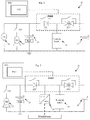
- Figure 1 and Figure 2 are diagrams of the electrical systems in two different types of vehicle.
- Figure 1 shows the electrical system 11 in a conventional car which is equipped with a stop start system.
- Figure 2 shows the electrical system 21 in a hybrid car.
- Both the conventional car and the hybrid comprise a starter motor 12, 22, a main battery 13, 23, various loads such as the engine management system, windscreen wipers etc 14, 24, and an auxiliary battery 15, 25, all of which are arranged in parallel.
- Both of the main batteries 13, 23 are provided with Battery Monitoring Systems (BMS).
- BMS Battery Monitoring Systems
- the conventional car comprises an alternator 16, which can provide power to the system when the internal combustion engine is running.
- the hybrid car comprises a DC/DC converter 26 which receives power from the electric motor/generator (not shown) and a high voltage battery (not shown).
- the DC/DC convertor 26 charges the batteries 23, 25.
- Each system also comprises three switches, ES1, ES2 and ES3, which can be used to isolate components from one another when necessary.
- the conventional car and the hybrid car are equipped with similar dual battery power supply systems, the operation of the switches ES1, ES2 and ES3 and the use of auxiliary batteries 15, 25 are very different.
- the hybrid car can stop and start the engine to save fuel, it is also equipped with an electric motor suitable for propelling the vehicle at low speeds.
- the DC/DC converter 26 is capable of supporting the electrical loads 24 while the internal combustion engine of the hybrid car is turned off, which an alternator 16 cannot do.
- Both the main and auxiliary batteries 13, 23, 15, 25 are typically 12V lead acid batteries.
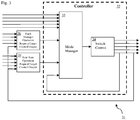
- FIG 3 is a diagram showing the high level functionality of software in a control unit 31 which can be used to control an electrical system such as the electrical systems 11, 21 shown in Figure 1 and Figure 2 .
- the control unit 31 must dynamically alter the network configuration of the electrical system 11, 21 in order to allow all the different system functions to be executed in the correct manner.
- the control unit 31 comprises a controller 32, which is able to operate the switches ES1 and ES2.
- the third switch, ES3, is not directly controlled by the controller 32.
- the controller 32 is able to give start permission to the starter motor, enabling the third switch ES3 to operate.
- the controller 32 can therefore switch various components in and out of the electrical network by operating ES1 and ES2.
- the controller 32 is provided with two software routines; the mode manager 33, and the switch control 34.
- the mode manager 33 and the switch control 34 operate in concert to select the correct configuration of ES1, ES2 and ES3.
- the mode manager 33 and the switch control 34 comprise various software sub functions. For purposes of clarity, only two example sub functions are illustrated in Figure 3 . These are the stop start sub function 35 and the fault manager sub function 36.
- Each sub-function is excited by an external operation request which, in turn, is raised according to a set of internal and external triggers.
- the triggers for a sub function can be real life variables such as sensor data, calculated parameters within the broader control functionality, or feedback signals from the controller 32 itself. All these together determine when a sub function can or should be executed.
- the fault manager sub function 36 is activated when a fault is detected within the vehicle, especially a fault with the electrical systems. For example, if a severe fault is detected with the auxiliary battery 15, 25, then the fault manager sub function 36 may cause ES2 to open and remain open, while the vehicle continues to operate without using the auxiliary battery 15, 25 in any way. In this condition, any stop-start or hybrid functionality will be suspended.
- a sub function may be provided to check on the state of charge of the auxiliary battery 15, 25.
- a sub function may be provided to charge the main battery 13, 23 or the auxiliary battery 15, 25, from the alternator 16 or the DC/DC converter 26.
- the cars may be provided with an off mode to function in whilst the car is shut down.
- an off sub function operates in the controller 32.
- ES1 and ES2 are opened as a part of the shutdown process.
- the diodes illustrated in the figures provide a route for quiescent current drain as necessary.
- the OFF mode follows naturally from the design of the switches; as the vehicle is turned off, the power to control the switches is lost and the switches open automatically.
- an accessory mode is provided.
- an accessory sub function operates and closes ES1 whilst keeping ES2 open. Power is then provided to the electrical loads from the main battery via ES1, so that devices such as the radio can operate.
- FIG 2 when the ignition is operated to start the car, different ignition modes can be selected.
- a first ignition mode the vehicle is started in the same manner as the vehicle illustrated in Figure 1 .
- the car may be started in an Electric Vehicle (EV) mode, where torque is provided to the wheels by an electrical motor.
- EV Electric Vehicle
- a second ignition mode may be used, in which the clutch is engaged and the engine is "push” started by the vehicle's momentum.
- a second ignition sub function operates and ensures that ES1 is closed and ES2 is open.
- the DC/DC converter 26 can provide power for the load 24, as well as for charging the main battery 23.
- the starter motor will be used to crank the engine. This is done with ES1 open and ES2 closed, the latter allowing power to flow from the auxiliary battery into the loads. During this time, the DCDC will also support the loads.
- both ES1 and ES2 may be closed so that the starter motor can draw current from both batteries when starting the engine.
- a vehicle which is expected to use the third ignition mode is typically provided with a larger auxiliary battery in expectation of its use in helping to start the engine.
- the hybrid car may enter a first engine running mode, in which a first engine running sub function operates and ensures that ES1 is closed and ES2 is open. Therefore the car's electrical load 24 is powered by the main battery 1 and the DC/DC converter 26, while the auxiliary battery 25 is kept disconnected in order to ensure it remains fully charged and ready for use.
- the hybrid car may enter a second engine running mode, in which a second engine running sub function operates and ensures that ES2 is closed and ES1 is also closed.
- the DC/DC converter then operates so that it charges the auxiliary battery 25 and provides power for the electrical load 24.
- the software referred to as the mode manager 33 administers the operation of the sub functions, deciding which sub functions are used.
- the length of time for which each sub function is used is determined by the sub function itself, subject to any higher priority sub function interrupting.
- the switch control in contrast, is very simple software. Its only job is to output the desired control targets, by operating the switches ES1 and ES2, as well as the switch ES3 indirectly.
- the control targets are task specific and their execution depends on the mode manager's permission to run.
- the fault manager sub function 35 would have to be high priority in such a case. This priority is to set the system in order to prevent damage to its components, whilst still allowing the car to be safely driven.
- the controller 32 will need to wait until it is reasonable to change sub function without interrupting the operation of the vehicle.
- the mode manager 33 uses a priority which is assigned to each sub function.
- the priority of the sub functions is preset.
- Sub functions are then issued a token according to their priority.
- the token represents permission for the sub function to operate, and to dictate the arrangement of the switches ES1, ES2, and indirectly of switch ES3.
- the sub function operates until the task it is intended to facilitate is complete, unless it is interrupted by another, higher priority, sub function.
- the mode manager 33 comprises a priority table, which determines at least a part of the priority of each sub function. This priority table lists all the possible sub functions associated with controlling the electrical flow between the 12V batteries, the electrical loads, and an alternator or DC/DC converter in a vehicle and assigns them a priority.
- the token for a sub function can be withdrawn or reassigned.
- the mode manager 33 can interrupt the presently executing sub function and assign a token for immediate use to the high priority sub function.
- the fault manager sub function 35 may be requested with a high enough priority to be given an immediate token and interrupt another operating sub function, such as the sub function for charging the main battery 13, 23 from the alternator 16 or DC/DC converter 26.
- the highest priority function will execute immediately. Otherwise it will wait until it is safe to change operation mode.
- Table 1 below, is a table showing an example set of sub functions and their priorities according to an example in a hybrid vehicle. Table 1 is therefore a part of a database as could be used. The set of sub functions shown is only a partial set, and more sub functions would typically be required for the successful operation of a vehicle. Table 1 Calibratable Value Range Res.
- the values in the column labelled "Calibratable” are the names of the various sub functions, and a description for each sub function is provided in the column labelled "Description".
- the priority of each sub function is indicated by the "Value” column, wherein a lower value indicates a higher priority. So the sub function ColdClimFcnFlg_Pt, which executes when a request for an engine crank is received while the external temperature is beneath a predetermined minimum, has a value of 1. Therefore ColdClimFcnFlg_Pt has the highest priority of any sub function and will execute whenever it is requested. Due to the nature of the sub function, ColdClimFcnFlg_Pt will only actually run if the vehicle is coming from a shut down status into a start up status.
- DfaltPostn_Pt is the default switch position.
- EVModeFlg_Pt is used when the vehicle is operating in an EV mode, with the internal combustion engine turned off and torque being provided to the wheels by an electric motor. If a request for EVModeFlg_Pt is received while in DfaltPostn_Pt, then EVModeFlg_Pt will execute immediately. Similarly, if a request for Batt2ChrgFlg_Pt, which is used to charge the auxiliary battery, is received while in EVModeFlg_Pt, then EVModeFlg_Pt will be interrupted so that the auxiliary battery can be charged in Batt2ChrgFlg_Pt. Before changing modes an engine re-crank would be requested and once it was detected the engine was running, the mode could then be changed.
- Figure 4 is a flow chart showing how a particular sub function is performed.
- the battery in a conventional vehicle is monitored for its condition via signals obtained from a Battery Monitoring System (BMS), which measures the battery temperature, battery voltage and battery current. With this information, the BMS derives the battery's State Of Charge (SOC), so that the battery can be charged as necessary.
- BMS Battery Monitoring System
- SOC State Of Charge
- the attributes of the auxiliary battery also require measurement if the battery is to be used properly.
- the performance of the auxiliary battery depends upon the auxiliary battery's SOC.
- another BMS module, attached to the auxiliary battery can be utilised to determine the SOC.
- BMS modules are expensive, and fitting an additional one increases the cost of manufacture. Therefore, if the estimation of the auxiliary battery SOC could be realised without the use of an auxiliary BMS module, this would result in a cost saving.
- the auxiliary battery 15, 25 After the auxiliary battery 15, 25 has been at rest for a long period of time its SOC can be estimated by measuring the voltage across the battery's terminals. Hence when the car has been turned off for over eight hours, the SOC of the auxiliary battery 15, 25, can be measured directly by a simple voltage measurement. This is known as the passive test.
- One method uses the current of the auxiliary battery, rather than the voltage, to estimate the auxiliary battery's state of charge. This is known as the active test.
- Figure 4 is a flow chart showing the active test, which is a process which might be used by the power management system in a vehicle as shown in Figure 1 to estimate the SOC of the auxiliary battery 15. (The same approach is taken with respect to Figure 2 , but the following description refers only to Figure 1 unless specified otherwise.)
- a first step S1 the power management system determines that such a test is necessary and submits a request for the test to be carried out.
- the request is submitted to a controller unit within the power management system which controls the arrangement of the switches ES1, ES2, and therefore controls whether the vehicle can be put into the correct state for carrying out the test.
- the controller unit checks that the conditions are valid for a test to be carried out. If they are valid, then the test proceeds.
- steps S3 and S4 a token is issued. The token represents permission for the test to proceed.
- step S5 ES1 is closed and ES2 is opened.
- the main battery 13 is providing all the power for the load 14.
- step S6 the power management system then uses the BMS to measure IB1, which is the current being produced by the main battery 13 at this stage. This measurement is recorded as IB1,0.
- step S7 ES2 is closed, so that both the main battery 13 and the auxiliary battery 15 are connected to the load 14. Again, the power management system waits five seconds (step S8) before measuring IB1 again. This measurement is recorded as IB1,1.
- IB 2 IB 1,0 ⁇ IB 1,1
- IB2 If IB2 is negative, this indicates that the current being drawn from the main battery 13 was reduced when the auxiliary battery 15 was connected. As such, the auxiliary battery 15 has a high enough capacity to contribute usefully to the load.
- IB2 If IB2 is positive, then this indicates that the current being drawn from the main battery 13 was increased when the auxiliary battery 15 was connected. As such, the auxiliary battery 15 does not have a high enough capacity to contribute usefully to the load.
- IB1,0 -40A.
- IB2 is related to the SOC of the auxiliary battery 15, as well as the SOC of the main battery.
- step S10 the power management system then compares the ratio CCrt to a threshold ratio Ct. If CCrt is greater than or equal to Ct then this indicates that the state of charge in the auxiliary battery 15 is too low. If CCrt is lower than or equal to Ct, then this indicates that the state of charge in the auxiliary battery 15 is adequate.
- Ct depends upon the size of the main battery 13 and the size of the auxiliary battery 15. However these are fixed variables and can be taken into account when designing the car and calibrating the power management system. More problematically, the ideal value for Ct also depends upon the temperature of the main and auxiliary batteries 13, 15. In particular, the internal resistance of each battery increases as the temperature of the electrolyte decreases. Therefore CCrt is related to the state of charge and the temperature of both batteries. As such Ct is variable with respect to the temperature of the batteries 13, 15.
- the BMS can provide a temperature for the main battery.
- the temperature of the auxiliary battery can either be provided by a dedicated temperature sensor or inferred from other known facts about the car.
- the auxiliary battery 15 may be located next to the main battery 13 under the bonnet of the vehicle.
- the temperature of the main battery 13 serves as an estimated value for the temperature of the auxiliary battery 15.
- a more complicated calculation may need to be made, based for example on the ambient temperature, the location of the battery in the car, and how long the car has been running.
- the appropriate value for Ct can be determined using a map relating temperatures to Ct for batteries with the known characteristics of the main battery 13 and the auxiliary battery 15.
- the load 14 in an electrical system such as the one shown in Figure 1 is subject to change over time.
- the driver may activate heated seats, or heating for the front or rear windscreen, both of which can change the load significantly.
- the power management system performs the check several times. As is shown at steps S11 and S12 in Figure 4 , each time the test is run, the power management system increments the counter SOC2 High if CCrt ⁇ Ct, and increments the counter SOC2Low if CCrt ⁇ Ct.
- step S13 Once SOC2High reaches the threshold SOC2HighMax (step S13), this is taken as an indication that the battery is sufficiently charged (step S14).
- the target SOC is an 80% charge
- SOC2HighMax is 3. Therefore, once the power management system receives three cumulative results indicating that the auxiliary battery 15 has at least an 80% charge, it is taken that the auxiliary battery 15 is charged and ready for use.
- step S15 SOC2Low reaches the threshold SOC2LowMax (step S15).
- SOC2LowMax is 3. Therefore, once the power management system receives three cumulative results indicating that the auxiliary battery 15 has less than an 80% charge, it is taken that the auxiliary battery 15 needs to be charged. To charge the auxiliary battery, the alternator 16 is reactivated and connected to the auxiliary battery 15.
- the power management system also increments a counter SOC2Run each time CCrt is measured (steps S11 and S12). If SOC2Run exceeds the threshold SOC2RunMax this is also taken as an indication that the battery is not sufficiently charged (step S17).
- the power management system monitors which other systems are active in the vehicle. If it appears that the load 14 will rise higher than can be safely supplied by the main and auxiliary batteries 13, 15, then the power management system interrupts the active test and reactivates the alternator 16.
- the power management system also monitors the state of charge of the main battery 13 during the test. If the state of charge of the main battery 13 falls below a safety threshold, then the test is interrupted and the alternator is used to support the loads. The test can then be re-initialised one the state of charge of the main battery 13 is high again.
- the auxiliary battery 25 in this figure can be monitored using the method outlined above. The only difference is that it is the DC/DC Converter 26 which is turned off, by setting the duty cycle, rather than an alternator 16.
- the power management system in a vehicle can initiate a check of the SOC in the auxiliary battery 15, 25 for a number of reasons.
- the power management system may be configured to carry out a check after a predetermined period of time has passed since the last such check.
- the power management system may be configured to perform a check immediately after the auxiliary battery 15, 25 has undergone a charging cycle. In this way the power management system can confirm that the auxiliary battery 15, 25 has been successfully charged.
- the power management system records this as an unsuccessful charging event and initiates a second charging cycle. This can happen if the load 14, 24 is high during the charging cycle, the load therefore drawing enough current to prevent an effective charging of the auxiliary battery 15, 25.
- an unsuccessful charging cycle can also indicate that the auxiliary battery needs to be serviced or replaced, especially if there are several unsuccessful charging cycles in a row.
- the power management system keeps a log of unsuccessful and successful charging events for use in servicing the car. If the number of unsuccessful charging events exceeds a minimum threshold, then a message is displayed to the driver recommending that the auxiliary battery 15, 25 be checked.
- a certain minimum load 14, 24 is required to ensure that the power management system can accurately estimate the SOC of the auxiliary battery 15, 25.
- the power management system may delay estimating the SOC until the load has risen above a predetermined minimum.
- the power management system may activate other power consuming systems in order to raise the load 14, 24 during a test cycle.
- typically the required load for an accurate estimate of the SOC of the auxiliary battery 15, 25 is close to the engine's base load, that is the minimum load that the engine can create while operational.
- the power management system can perform a correction of the estimated state of charge in the auxiliary battery 15, 25 if the car has been turned off for a long enough period of time, typically eight hours. To perform the correction, the power management system performs a passive test, by measuring the voltage across the terminals of the auxiliary battery 15, 25. The power management system then compares the result of the passive test with the last known result of the active test, and uses the result of the passive test if there is any disagreement.
- the power management system can perform a calibration check if the car has been turned off for a long enough period of time.
- the power management system first performs a passive test, by measuring the voltage across the terminals of the auxiliary battery 15, 25.
- the power management system then performs an active test, by disconnecting and connecting the batteries as described above.
- the passive test is performed first so that the results are not distorted by the discharging which occurs during the active test.
- the power management system compares the results of the two tests and calibrates the active test according to the results of the passive test.
- the power management system can adapt if the characteristics of the main and auxiliary batteries 13, 23, 15, 25 change as they age.
Landscapes
- Engineering & Computer Science (AREA)
- Mechanical Engineering (AREA)
- Power Engineering (AREA)
- Transportation (AREA)
- Chemical & Material Sciences (AREA)
- Combustion & Propulsion (AREA)
- Life Sciences & Earth Sciences (AREA)
- Sustainable Development (AREA)
- Sustainable Energy (AREA)
- Automation & Control Theory (AREA)
- Electric Propulsion And Braking For Vehicles (AREA)
- Charge And Discharge Circuits For Batteries Or The Like (AREA)
- Hybrid Electric Vehicles (AREA)
- Control Of Driving Devices And Active Controlling Of Vehicle (AREA)
Claims (13)
- Verfahren zum Steuern eines elektrischen Systems (11; 21) in einem Fahrzeug, wobei das elektrische System Folgendes umfasst:wenigstens einen ersten Schalter und einen zweiten Schalter (ES1, ES2), die derart angeordnet sind, dass ein Betreiben der Schalter Teile des elektrischen Systems trennen wird, das durch die Schalter gesteuert wird; undeine Steuereinheit (31), wobei die Steuereinheit angeordnet ist, um die Schalter zu betreiben, wobei das elektrische System einen Hauptakku (13; 23) und einen Zusatzakku (15; 25) umfasst, wobei der erste Schalter derart angeordnet ist, dass das Betreiben des ersten Schalters den Zusatzakku von wenigstens einer Komponente innerhalb des elektrischen Systems trennt,wobei das Verfahren durch Folgendes gekennzeichnet ist:Versetzen der Steuereinheit (31) in einen ersten Betriebsmodus, wobei der erste Betriebsmodus wenigstens eine erste Anordnung von Schaltern (ES1, ES2, ES3) umfasst;Empfangen einer Anforderung in der Steuereinheit, um in einen zweiten Betriebsmodus einzutreten, wobei der zweite Betriebsmodus wenigstens eine zweite Anordnung der Schalter umfasst;Bestimmen der Priorität des ersten und des zweiten Betriebsmodus wenigstens teilweise durch Konsultieren einer Datenbank von Betriebsmodi und ihren Prioritäten;Umschalten der Steuereinheit (31) in den zweiten Betriebsmodus, falls der zweite Betriebsmodus eine höhere Priorität als der erste Betriebsmodus aufweist oder wenn der erste Betriebsmodus aufhört.
- Verfahren nach Anspruch 1, wobei das Verfahren Folgendes umfasst:Betreiben in dem zweiten Betriebsmodus für eine Betriebsdauer; undUmschalten der Steuereinheit (31) in den ersten Betriebsmodus, wenn die Betriebsdauer beendet ist.
- Verfahren nach Anspruch 1 oder 2, wobei das Verfahren Folgendes umfasst:Empfangen einer Anforderung, um während in dem zweiten Betriebsmodus in einen dritten Betriebsmodus einzutreten, wobei der dritte Betriebsmodus wenigstens eine dritte Anordnung von Schaltern (ES1, ES2, ES3) umfasst;Bestimmen der Priorität des zweiten und des dritten Betriebsmodus wenigstens teilweise durch Konsultieren der Datenbank von Betriebsmodi und ihren Prioritäten;Umschalten der Steuereinheit (31) in den dritten Betriebsmodus, wenn die Betriebsdauer beendet ist, falls der dritte Betriebsmodus eine höhere Priorität als der erste Betriebsmodus aufweist; undUmschalten der Steuereinheit (31) in den ersten Betriebsmodus, wenn die Betriebsdauer sonst beendet ist.
- Verfahren nach einem der vorhergehenden Ansprüche, wobei das Verfahren Folgendes umfasst:Empfangen einer Anforderung, um während in dem zweiten Betriebsmodus in einen dritten Betriebsmodus einzutreten, wobei der dritte Betriebsmodus wenigstens eine dritte Anordnung von Schaltern (ES1, ES2, ES3) umfasst;Bestimmen der Priorität des ersten, zweiten und dritten Betriebsmodus wenigstens teilweise durch Konsultieren der Datenbank von Betriebsmodi und ihren Prioritäten; undsofortiges Umschalten der Steuereinheit (31) in den dritten Betriebsmodus nur dann, wenn der dritte Betriebsmodus eine höhere Priorität als der erste und der zweite Betriebsmodus aufweist.
- Verfahren nach Anspruch 4, wobei der zweite Betriebsmodus nicht durch einen dritten Betriebsmodus ersetzt werden kann, wenn der zweite Betriebsmodus betriebsbereit ist, es sei denn, der dritte Betriebsmodus weist eine Priorität über einem zuvor bestimmten Minimum auf, wobei die Priorität des zuvor bestimmten Minimums höher als die Priorität des zweiten Betriebsmodus ist.
- Verfahren nach einem der vorhergehenden Ansprüche, wobei die Priorität wenigstens des zweiten Modus mit der Zeit zunimmt, nachdem eine Anforderung für den zweiten Modus gestellt wurde, während der zweite Modus nicht in Betrieb ist.
- Verfahren nach einem der vorhergehenden Ansprüche, wobei die Priorität wenigstens des zweiten Modus teilweise durch die Anforderung bestimmt wird.
- Verfahren nach Anspruch 7, wobei die Anforderung einen Faktor beinhaltet, der sich auf die Dringlichkeit der Anforderung bezieht, wobei der Fakt dazu dient, die Priorität des zweiten Modus wie aus der Datenbank abgerufen zu ändern,
und wobei sich der Faktor auf den Ladezustand des Zusatzakkus (15; 25) bezieht. - Verfahren nach einem der vorhergehenden Ansprüche, wobei die Datenbank eine Liste von Betriebsmodi umfasst, die einen ersten Betriebsmodus und einen zweiten Betriebsmodus beinhalten, wobei jeder Betriebsmodus mit einem Wert verknüpft ist, der die Priorität dieses Betriebsmodus darstellt.
- Elektrisches System (11; 21) zur Verwendung in einem Fahrzeug, wobei das elektrische System Folgendes umfasst:wenigstens einen ersten Schalter und einen zweiten Schalter (ES1, ES2), die derart angeordnet sind, dass das Betreiben der Schalter Teile des elektrischen Systems trennen wird; wobei das elektrische System einen Hauptakku (13; 23) und einen Zusatzakku (15; 25) umfasst, wobei der erste Schalter derart angeordnet ist, dass das Betreiben des ersten Schalters den Zusatzakku von wenigstens einer Komponente innerhalb des elektrischen Systems trennt,eine Steuereinheit (31), wobei die Steuereinheit angeordnet ist, um die Schalter zu betreiben; wobei das elektrische System durch Folgendes gekennzeichnet ist:eine Datenbank von Betriebsmodi und ihren Prioritäten, wobei die Betriebsmodi wenigstens unterschiedliche Anordnungen der Schalter umfassen,wobei die Steuereinheit (31) angeordnet ist, um das elektrische System (11; 21) nach dem Verfahren nach einem vorhergehenden Anspruch zu steuern.
- Fahrzeug, das ein elektrisches System (11; 21) nach Anspruch 10 umfasst.
- Fahrzeug nach Anspruch 11, wobei das Fahrzeug einen Verbrennungsmotor und eine elektrische Last (14; 24) umfasst, wobei der Hauptakku (13; 23) konfiguriert ist, um einen Starter (12; 22) für den Motor mit Leistung zu versorgen; und
wobei der erste und der zweite Schalter (ES1; ES2) mit dem Hauptakku beziehungsweise dem Zusatzakku verbunden sind, um den Hauptakku und den Zusatzakku mit der elektrischen Last wahlweise zu verbinden. - Fahrzeug nach Anspruch 12, wobei die Betriebsmodi aus der Gruppe ausgewählt sind, die Folgendes umfasst:a) wobei der Hauptakku (13; 23) mit der elektrischen Last (14; 24) verbunden ist und der Zusatzakku (15; 25) davon getrennt ist, der ein normalantreibender Betriebsmodus ist;b) wobei der Hauptakku (13; 23) mit dem Starter (12; 22) verbunden ist und der Zusatzakku (15; 25) mit der elektrischen Last (14; 24) verbunden ist, der ein Betriebsmodus für ein Starten des Motors während eines Stopp-Start-Betriebsmodus ist;c) wobei der Hauptakku (13; 23) mit der elektrischen Last (14; 24) verbunden ist und der Zusatzakku (15; 25) mit dem Generator verbunden ist, der ein Zusatzakkuladebetriebsmodus ist;d) eine Sequenz von Verbindungen, wobei:wodurch die Ladung des Zusatzakkus (15; 25) geschätzt werden kann.i) erstens der Hauptakku (13; 23) mit der elektrischen Last (14; 24) verbunden ist und der Zusatzakku (15; 25) davon getrennt ist, wobei ein erster Stromverbrauch an dem Hauptakku gemessen wird, undii) zweitens der Hauptakku (13; 23) und der Zusatzakku (15; 25) mit der elektrischen Last (14; 24) verbunden sind, wobei ein zweiter Stromverbrauch an dem Hauptakku gemessen wird,
Applications Claiming Priority (2)
| Application Number | Priority Date | Filing Date | Title |
|---|---|---|---|
| GB1216128.7A GB2505707B (en) | 2012-09-11 | 2012-09-11 | A method for controlling an electrical system in a vehicle |
| PCT/EP2013/068857 WO2014041043A2 (en) | 2012-09-11 | 2013-09-11 | A method for controlling an electrical system in a vehicle |
Publications (2)
| Publication Number | Publication Date |
|---|---|
| EP2896107A2 EP2896107A2 (de) | 2015-07-22 |
| EP2896107B1 true EP2896107B1 (de) | 2021-06-30 |
Family
ID=47137204
Family Applications (1)
| Application Number | Title | Priority Date | Filing Date |
|---|---|---|---|
| EP13782981.8A Active EP2896107B1 (de) | 2012-09-11 | 2013-09-11 | Verfahren zur steuerung eines elektrischen systems in einem fahrzeug |
Country Status (6)
| Country | Link |
|---|---|
| US (1) | US9597963B2 (de) |
| EP (1) | EP2896107B1 (de) |
| JP (2) | JP2015530861A (de) |
| CN (1) | CN104769809B (de) |
| GB (1) | GB2505707B (de) |
| WO (1) | WO2014041043A2 (de) |
Families Citing this family (23)
| Publication number | Priority date | Publication date | Assignee | Title |
|---|---|---|---|---|
| GB2505707B (en) * | 2012-09-11 | 2015-04-15 | Jaguar Land Rover Ltd | A method for controlling an electrical system in a vehicle |
| JP2015144517A (ja) * | 2014-01-31 | 2015-08-06 | 株式会社デンソー | 電子制御装置 |
| US9358968B2 (en) * | 2014-07-25 | 2016-06-07 | Ford Global Technologies, Llc | Cold temperature engine start |
| JP5977855B1 (ja) * | 2015-03-31 | 2016-08-24 | 富士重工業株式会社 | 車両用電源装置 |
| FR3042920A1 (fr) * | 2015-10-23 | 2017-04-28 | Peugeot Citroen Automobiles Sa | Procede de commande d’un dispositif electrique multifonction |
| GB2552506B (en) * | 2016-07-26 | 2020-04-01 | Ford Global Tech Llc | A battery system |
| CN107972498A (zh) * | 2016-10-21 | 2018-05-01 | 蔚来汽车有限公司 | 用于电动交通工具的功率分配方法及系统 |
| US10635066B2 (en) | 2016-12-19 | 2020-04-28 | Kohler Co. | Generator system architecture |
| CN107482708B (zh) * | 2017-07-28 | 2021-03-23 | 惠州华阳通用电子有限公司 | 一种车载系统欠压控制方法及装置 |
| US11104247B2 (en) * | 2017-12-28 | 2021-08-31 | Gregory Barazowski | Dual battery electric vehicle charging system |
| US10714966B2 (en) * | 2018-04-18 | 2020-07-14 | Ford Global Technologies, Llc | Isolation switch operation |
| EP3663121B1 (de) * | 2018-12-03 | 2023-09-27 | Volvo Car Corporation | Verfahren und system zur steuerung eines elektrischen systems |
| US11338811B2 (en) | 2019-09-05 | 2022-05-24 | Aptiv Technologies Limited | Mode selector module for a vehicle component |
| JP7412675B2 (ja) * | 2019-09-27 | 2024-01-15 | マツダ株式会社 | 車両の電源制御装置 |
| JP7406472B2 (ja) * | 2020-08-18 | 2023-12-27 | 株式会社Subaru | 車両の電源システム |
| CN112193183B (zh) * | 2020-09-28 | 2022-04-01 | 长城汽车股份有限公司 | 隔离部件、自动驾驶车辆冗余架构及隔离部件控制方法 |
| US11820448B2 (en) * | 2020-10-01 | 2023-11-21 | Steering Solutions Ip Holding Corporation | Infinite steering mode |
| US11628740B2 (en) | 2020-10-29 | 2023-04-18 | Argo AI, LLC | Devices, systems, and methods for mitigating vehicle power loss in battery mode |
| JP7210521B2 (ja) * | 2020-11-05 | 2023-01-23 | 矢崎総業株式会社 | 電源切換制御システム |
| US11982694B2 (en) * | 2021-04-15 | 2024-05-14 | Mgl Global Solutions Limited | Electronic device and method for operating the same |
| TWI891768B (zh) * | 2021-04-15 | 2025-08-01 | 香港商邁世集團國際有限公司 | 電子裝置及其操作方法 |
| CN114162070B (zh) * | 2021-12-06 | 2024-12-13 | 中国铁建高新装备股份有限公司 | 供配电系统、方法及车辆 |
| EP4206025A1 (de) * | 2021-12-31 | 2023-07-05 | Volvo Car Corporation | Batterieanordnung für ein elektrofahrzeug, fahrzeug und verfahren zum betrieb eines elektrofahrzeugs |
Citations (1)
| Publication number | Priority date | Publication date | Assignee | Title |
|---|---|---|---|---|
| US6718214B1 (en) * | 1998-12-15 | 2004-04-06 | Robert Bosch Gmbh | Method for switching consumer on or off |
Family Cites Families (26)
| Publication number | Priority date | Publication date | Assignee | Title |
|---|---|---|---|---|
| JPH04108343U (ja) | 1991-03-06 | 1992-09-18 | 沖電気工業株式会社 | バツテリ充電回路 |
| US5164655A (en) * | 1991-08-05 | 1992-11-17 | Dimensions Unlimited, Inc. | 12-24 volt power system |
| JP3886733B2 (ja) * | 2001-04-03 | 2007-02-28 | 矢崎総業株式会社 | 車両用電源装置 |
| JP4120418B2 (ja) * | 2003-02-17 | 2008-07-16 | 株式会社デンソー | 自動車用電源装置 |
| EP2154028B8 (de) | 2003-02-17 | 2015-12-09 | Denso Corporation | Fahrzeugstromversorgungssystem |
| US7157806B2 (en) * | 2004-03-12 | 2007-01-02 | C. E. Niehoff & Co. | System and method for controlling and distributing electrical energy in a vehicle |
| US8026698B2 (en) * | 2006-02-09 | 2011-09-27 | Scheucher Karl F | Scalable intelligent power supply system and method |
| JP2007237913A (ja) * | 2006-03-08 | 2007-09-20 | Toyota Infotechnology Center Co Ltd | 車載装置制御システムおよび車両 |
| JP4631824B2 (ja) * | 2006-07-31 | 2011-02-16 | 株式会社デンソー | オートクルーズ装置およびプログラム |
| EP1943894B1 (de) * | 2007-01-15 | 2010-05-19 | Kanzaki Kokyukoki Mfg. Co., Ltd. | Rasenmäher |
| JP4874874B2 (ja) * | 2007-06-06 | 2012-02-15 | トヨタ自動車株式会社 | 車両の電源装置 |
| JP4527138B2 (ja) * | 2007-07-12 | 2010-08-18 | 本田技研工業株式会社 | ハイブリッド車両の制御装置 |
| GB2458677B (en) * | 2008-03-27 | 2012-08-08 | Ford Global Tech Llc | Dual battery vehicle electrical systems |
| JP5024626B2 (ja) * | 2008-03-28 | 2012-09-12 | スズキ株式会社 | 車両用発電機の制御装置 |
| JP4624448B2 (ja) * | 2008-07-30 | 2011-02-02 | 株式会社オートネットワーク技術研究所 | 制御装置、制御システム及びコンピュータプログラム |
| GB0908482D0 (en) * | 2009-05-18 | 2009-06-24 | Liberty Electric Cars Ltd | Multi component propulsion systems for road vehicles |
| JP2010272965A (ja) * | 2009-05-19 | 2010-12-02 | Ntt Docomo Inc | 移動端末及び動作モード切替方法 |
| WO2011014597A2 (en) * | 2009-07-31 | 2011-02-03 | Thermo King Corporation | Bi-directional battery voltage converter |
| US8288887B2 (en) * | 2009-11-19 | 2012-10-16 | GM Global Technology Operations LLC | Systems and methods for commutating inductor current using a matrix converter |
| JP2011172318A (ja) | 2010-02-16 | 2011-09-01 | Omron Automotive Electronics Co Ltd | 電源システムおよび電源制御方法 |
| DE102010013569A1 (de) | 2010-03-30 | 2011-10-06 | Gm Global Technology Operations Llc (N.D.Ges.D. Staates Delaware) | Versorgungsschaltung für die elektrische Versorgung eines Fahrzeugs |
| JP2011208599A (ja) * | 2010-03-30 | 2011-10-20 | Panasonic Corp | 車両用電源装置 |
| ES2392390T3 (es) | 2010-05-25 | 2012-12-10 | Fiat Group Automobiles S.P.A. | Gestión del funcionamiento del sistema eléctrico de un automóvil durante la marcha en el punto muerto y/o cuando el motor está parado |
| JP5143867B2 (ja) * | 2010-06-11 | 2013-02-13 | 株式会社シマノ | 自転車用の電装品制御システム |
| JP5644360B2 (ja) * | 2010-10-22 | 2014-12-24 | 日産自動車株式会社 | 車両用走行制御装置及び車両用走行制御方法 |
| GB2505707B (en) * | 2012-09-11 | 2015-04-15 | Jaguar Land Rover Ltd | A method for controlling an electrical system in a vehicle |
-
2012
- 2012-09-11 GB GB1216128.7A patent/GB2505707B/en active Active
-
2013
- 2013-09-11 EP EP13782981.8A patent/EP2896107B1/de active Active
- 2013-09-11 JP JP2015530458A patent/JP2015530861A/ja active Pending
- 2013-09-11 WO PCT/EP2013/068857 patent/WO2014041043A2/en not_active Ceased
- 2013-09-11 CN CN201380047327.8A patent/CN104769809B/zh not_active Expired - Fee Related
- 2013-09-11 US US14/426,191 patent/US9597963B2/en active Active
-
2017
- 2017-03-29 JP JP2017065825A patent/JP2017131106A/ja active Pending
Patent Citations (1)
| Publication number | Priority date | Publication date | Assignee | Title |
|---|---|---|---|---|
| US6718214B1 (en) * | 1998-12-15 | 2004-04-06 | Robert Bosch Gmbh | Method for switching consumer on or off |
Also Published As
| Publication number | Publication date |
|---|---|
| JP2015530861A (ja) | 2015-10-15 |
| WO2014041043A3 (en) | 2014-10-30 |
| GB2505707B (en) | 2015-04-15 |
| GB201216128D0 (en) | 2012-10-24 |
| WO2014041043A2 (en) | 2014-03-20 |
| CN104769809A (zh) | 2015-07-08 |
| GB2505707A (en) | 2014-03-12 |
| EP2896107A2 (de) | 2015-07-22 |
| US9597963B2 (en) | 2017-03-21 |
| CN104769809B (zh) | 2017-12-15 |
| US20150217641A1 (en) | 2015-08-06 |
| JP2017131106A (ja) | 2017-07-27 |
Similar Documents
| Publication | Publication Date | Title |
|---|---|---|
| EP2896107B1 (de) | Verfahren zur steuerung eines elektrischen systems in einem fahrzeug | |
| EP2896106B1 (de) | Verfahren zur bestimmung des ladezustands einer fahrzeugbatterie | |
| EP3417304B1 (de) | Systeme und verfahren zur echtzeitparameterschätzung einer wiederaufladbaren batterie | |
| US7570021B2 (en) | Rechargeable battery controller and method for controlling output of rechargeable battery | |
| EP3417302B1 (de) | Systeme und verfahren zur direktionalen kapazitätsschätzung eines akkumulators | |
| US10611257B2 (en) | Control apparatus of electric vehicle | |
| RU2633439C2 (ru) | Способ обеспечения максимального использования старт-стопной системы для микрогибридных автомобилей | |
| US11054476B2 (en) | Method for monitoring a status of a battery, monitoring device and motor vehicle | |
| CN104904092A (zh) | 能量存储控制系统和方法 | |
| US20150210284A1 (en) | Driving environment estimation apparatus and method thereof | |
| CN103003093B (zh) | 用于在车辆中激活至少一个能量管理功能的方法和装置 | |
| JP7115409B2 (ja) | 駆動システムの制御装置 | |
| KR100906872B1 (ko) | 하이브리드 차량의 배터리 성능 보상 및 soc 초기화방법 | |
| US12319169B2 (en) | Method of preventing output limit of battery of vehicle | |
| CN113258163A (zh) | 电池温度的控制方法及装置 | |
| EP3844381A1 (de) | Fahrzeugsteuerungssystem, verfahren, gerät und vorrichtung | |
| CN103359026B (zh) | 用于激活在车辆中至少一个能量管理功能的方法和装置 | |
| US20250303917A1 (en) | Techniques for ensuring propulsion system enablement and low voltage system protection by supervising thermal devices in electrified vehicles | |
| JP2003244805A (ja) | 電池の満充電容量計測装置、計測方法、その計測装置を搭載した車両の制御装置および制御方法 | |
| US20100191448A1 (en) | Operating method for an internal combustion engine and associated motor vehicle |
Legal Events
| Date | Code | Title | Description |
|---|---|---|---|
| PUAI | Public reference made under article 153(3) epc to a published international application that has entered the european phase |
Free format text: ORIGINAL CODE: 0009012 |
|
| 17P | Request for examination filed |
Effective date: 20150430 |
|
| AK | Designated contracting states |
Kind code of ref document: A2 Designated state(s): AL AT BE BG CH CY CZ DE DK EE ES FI FR GB GR HR HU IE IS IT LI LT LU LV MC MK MT NL NO PL PT RO RS SE SI SK SM TR |
|
| AX | Request for extension of the european patent |
Extension state: BA ME |
|
| DAX | Request for extension of the european patent (deleted) | ||
| STAA | Information on the status of an ep patent application or granted ep patent |
Free format text: STATUS: EXAMINATION IS IN PROGRESS |
|
| 17Q | First examination report despatched |
Effective date: 20170829 |
|
| GRAP | Despatch of communication of intention to grant a patent |
Free format text: ORIGINAL CODE: EPIDOSNIGR1 |
|
| STAA | Information on the status of an ep patent application or granted ep patent |
Free format text: STATUS: GRANT OF PATENT IS INTENDED |
|
| RIC1 | Information provided on ipc code assigned before grant |
Ipc: B60W 10/24 20060101ALI20201218BHEP Ipc: H02J 7/34 20060101ALI20201218BHEP Ipc: H02J 7/14 20060101AFI20201218BHEP Ipc: B60R 16/03 20060101ALI20201218BHEP Ipc: B60L 50/60 20190101ALI20201218BHEP Ipc: H02J 7/00 20060101ALN20201218BHEP Ipc: B60L 58/12 20190101ALN20201218BHEP Ipc: B60W 10/26 20060101ALI20201218BHEP |
|
| INTG | Intention to grant announced |
Effective date: 20210120 |
|
| GRAS | Grant fee paid |
Free format text: ORIGINAL CODE: EPIDOSNIGR3 |
|
| GRAA | (expected) grant |
Free format text: ORIGINAL CODE: 0009210 |
|
| STAA | Information on the status of an ep patent application or granted ep patent |
Free format text: STATUS: THE PATENT HAS BEEN GRANTED |
|
| RBV | Designated contracting states (corrected) |
Designated state(s): AL AT BE BG CH CY CZ DE DK EE ES FI FR GR HR HU IE IS IT LI LT LU LV MC MK MT NL NO PL PT RO RS SE SI SK SM TR |
|
| AK | Designated contracting states |
Kind code of ref document: B1 Designated state(s): AL AT BE BG CH CY CZ DE DK EE ES FI FR GR HR HU IE IS IT LI LT LU LV MC MK MT NL NO PL PT RO RS SE SI SK SM TR |
|
| REG | Reference to a national code |
Ref country code: CH Ref legal event code: EP |
|
| REG | Reference to a national code |
Ref country code: AT Ref legal event code: REF Ref document number: 1407253 Country of ref document: AT Kind code of ref document: T Effective date: 20210715 |
|
| REG | Reference to a national code |
Ref country code: DE Ref legal event code: R096 Ref document number: 602013078157 Country of ref document: DE |
|
| REG | Reference to a national code |
Ref country code: IE Ref legal event code: FG4D |
|
| REG | Reference to a national code |
Ref country code: LT Ref legal event code: MG9D |
|
| PG25 | Lapsed in a contracting state [announced via postgrant information from national office to epo] |
Ref country code: FI Free format text: LAPSE BECAUSE OF FAILURE TO SUBMIT A TRANSLATION OF THE DESCRIPTION OR TO PAY THE FEE WITHIN THE PRESCRIBED TIME-LIMIT Effective date: 20210630 Ref country code: BG Free format text: LAPSE BECAUSE OF FAILURE TO SUBMIT A TRANSLATION OF THE DESCRIPTION OR TO PAY THE FEE WITHIN THE PRESCRIBED TIME-LIMIT Effective date: 20210930 Ref country code: HR Free format text: LAPSE BECAUSE OF FAILURE TO SUBMIT A TRANSLATION OF THE DESCRIPTION OR TO PAY THE FEE WITHIN THE PRESCRIBED TIME-LIMIT Effective date: 20210630 |
|
| REG | Reference to a national code |
Ref country code: NL Ref legal event code: MP Effective date: 20210630 |
|
| REG | Reference to a national code |
Ref country code: AT Ref legal event code: MK05 Ref document number: 1407253 Country of ref document: AT Kind code of ref document: T Effective date: 20210630 |
|
| PG25 | Lapsed in a contracting state [announced via postgrant information from national office to epo] |
Ref country code: RS Free format text: LAPSE BECAUSE OF FAILURE TO SUBMIT A TRANSLATION OF THE DESCRIPTION OR TO PAY THE FEE WITHIN THE PRESCRIBED TIME-LIMIT Effective date: 20210630 Ref country code: SE Free format text: LAPSE BECAUSE OF FAILURE TO SUBMIT A TRANSLATION OF THE DESCRIPTION OR TO PAY THE FEE WITHIN THE PRESCRIBED TIME-LIMIT Effective date: 20210630 Ref country code: NO Free format text: LAPSE BECAUSE OF FAILURE TO SUBMIT A TRANSLATION OF THE DESCRIPTION OR TO PAY THE FEE WITHIN THE PRESCRIBED TIME-LIMIT Effective date: 20210930 Ref country code: LV Free format text: LAPSE BECAUSE OF FAILURE TO SUBMIT A TRANSLATION OF THE DESCRIPTION OR TO PAY THE FEE WITHIN THE PRESCRIBED TIME-LIMIT Effective date: 20210630 Ref country code: GR Free format text: LAPSE BECAUSE OF FAILURE TO SUBMIT A TRANSLATION OF THE DESCRIPTION OR TO PAY THE FEE WITHIN THE PRESCRIBED TIME-LIMIT Effective date: 20211001 |
|
| PG25 | Lapsed in a contracting state [announced via postgrant information from national office to epo] |
Ref country code: AT Free format text: LAPSE BECAUSE OF FAILURE TO SUBMIT A TRANSLATION OF THE DESCRIPTION OR TO PAY THE FEE WITHIN THE PRESCRIBED TIME-LIMIT Effective date: 20210630 Ref country code: NL Free format text: LAPSE BECAUSE OF FAILURE TO SUBMIT A TRANSLATION OF THE DESCRIPTION OR TO PAY THE FEE WITHIN THE PRESCRIBED TIME-LIMIT Effective date: 20210630 Ref country code: PT Free format text: LAPSE BECAUSE OF FAILURE TO SUBMIT A TRANSLATION OF THE DESCRIPTION OR TO PAY THE FEE WITHIN THE PRESCRIBED TIME-LIMIT Effective date: 20211102 Ref country code: RO Free format text: LAPSE BECAUSE OF FAILURE TO SUBMIT A TRANSLATION OF THE DESCRIPTION OR TO PAY THE FEE WITHIN THE PRESCRIBED TIME-LIMIT Effective date: 20210630 Ref country code: ES Free format text: LAPSE BECAUSE OF FAILURE TO SUBMIT A TRANSLATION OF THE DESCRIPTION OR TO PAY THE FEE WITHIN THE PRESCRIBED TIME-LIMIT Effective date: 20210630 Ref country code: SK Free format text: LAPSE BECAUSE OF FAILURE TO SUBMIT A TRANSLATION OF THE DESCRIPTION OR TO PAY THE FEE WITHIN THE PRESCRIBED TIME-LIMIT Effective date: 20210630 Ref country code: SM Free format text: LAPSE BECAUSE OF FAILURE TO SUBMIT A TRANSLATION OF THE DESCRIPTION OR TO PAY THE FEE WITHIN THE PRESCRIBED TIME-LIMIT Effective date: 20210630 Ref country code: CZ Free format text: LAPSE BECAUSE OF FAILURE TO SUBMIT A TRANSLATION OF THE DESCRIPTION OR TO PAY THE FEE WITHIN THE PRESCRIBED TIME-LIMIT Effective date: 20210630 Ref country code: EE Free format text: LAPSE BECAUSE OF FAILURE TO SUBMIT A TRANSLATION OF THE DESCRIPTION OR TO PAY THE FEE WITHIN THE PRESCRIBED TIME-LIMIT Effective date: 20210630 |
|
| PG25 | Lapsed in a contracting state [announced via postgrant information from national office to epo] |
Ref country code: PL Free format text: LAPSE BECAUSE OF FAILURE TO SUBMIT A TRANSLATION OF THE DESCRIPTION OR TO PAY THE FEE WITHIN THE PRESCRIBED TIME-LIMIT Effective date: 20210630 |
|
| REG | Reference to a national code |
Ref country code: DE Ref legal event code: R097 Ref document number: 602013078157 Country of ref document: DE |
|
| PG25 | Lapsed in a contracting state [announced via postgrant information from national office to epo] |
Ref country code: DK Free format text: LAPSE BECAUSE OF FAILURE TO SUBMIT A TRANSLATION OF THE DESCRIPTION OR TO PAY THE FEE WITHIN THE PRESCRIBED TIME-LIMIT Effective date: 20210630 |
|
| REG | Reference to a national code |
Ref country code: CH Ref legal event code: PL |
|
| PLBE | No opposition filed within time limit |
Free format text: ORIGINAL CODE: 0009261 |
|
| STAA | Information on the status of an ep patent application or granted ep patent |
Free format text: STATUS: NO OPPOSITION FILED WITHIN TIME LIMIT |
|
| REG | Reference to a national code |
Ref country code: BE Ref legal event code: MM Effective date: 20210930 |
|
| PG25 | Lapsed in a contracting state [announced via postgrant information from national office to epo] |
Ref country code: MC Free format text: LAPSE BECAUSE OF FAILURE TO SUBMIT A TRANSLATION OF THE DESCRIPTION OR TO PAY THE FEE WITHIN THE PRESCRIBED TIME-LIMIT Effective date: 20210630 Ref country code: AL Free format text: LAPSE BECAUSE OF FAILURE TO SUBMIT A TRANSLATION OF THE DESCRIPTION OR TO PAY THE FEE WITHIN THE PRESCRIBED TIME-LIMIT Effective date: 20210630 |
|
| 26N | No opposition filed |
Effective date: 20220331 |
|
| PG25 | Lapsed in a contracting state [announced via postgrant information from national office to epo] |
Ref country code: LU Free format text: LAPSE BECAUSE OF NON-PAYMENT OF DUE FEES Effective date: 20210911 Ref country code: IT Free format text: LAPSE BECAUSE OF FAILURE TO SUBMIT A TRANSLATION OF THE DESCRIPTION OR TO PAY THE FEE WITHIN THE PRESCRIBED TIME-LIMIT Effective date: 20210630 Ref country code: IE Free format text: LAPSE BECAUSE OF NON-PAYMENT OF DUE FEES Effective date: 20210911 Ref country code: BE Free format text: LAPSE BECAUSE OF NON-PAYMENT OF DUE FEES Effective date: 20210930 |
|
| PG25 | Lapsed in a contracting state [announced via postgrant information from national office to epo] |
Ref country code: LI Free format text: LAPSE BECAUSE OF NON-PAYMENT OF DUE FEES Effective date: 20210930 Ref country code: CH Free format text: LAPSE BECAUSE OF NON-PAYMENT OF DUE FEES Effective date: 20210930 |
|
| PG25 | Lapsed in a contracting state [announced via postgrant information from national office to epo] |
Ref country code: LT Free format text: LAPSE BECAUSE OF FAILURE TO SUBMIT A TRANSLATION OF THE DESCRIPTION OR TO PAY THE FEE WITHIN THE PRESCRIBED TIME-LIMIT Effective date: 20210630 |
|
| PG25 | Lapsed in a contracting state [announced via postgrant information from national office to epo] |
Ref country code: HU Free format text: LAPSE BECAUSE OF FAILURE TO SUBMIT A TRANSLATION OF THE DESCRIPTION OR TO PAY THE FEE WITHIN THE PRESCRIBED TIME-LIMIT; INVALID AB INITIO Effective date: 20130911 |
|
| PG25 | Lapsed in a contracting state [announced via postgrant information from national office to epo] |
Ref country code: CY Free format text: LAPSE BECAUSE OF FAILURE TO SUBMIT A TRANSLATION OF THE DESCRIPTION OR TO PAY THE FEE WITHIN THE PRESCRIBED TIME-LIMIT Effective date: 20210630 |
|
| P01 | Opt-out of the competence of the unified patent court (upc) registered |
Effective date: 20230528 |
|
| PG25 | Lapsed in a contracting state [announced via postgrant information from national office to epo] |
Ref country code: MK Free format text: LAPSE BECAUSE OF FAILURE TO SUBMIT A TRANSLATION OF THE DESCRIPTION OR TO PAY THE FEE WITHIN THE PRESCRIBED TIME-LIMIT Effective date: 20210630 |
|
| PG25 | Lapsed in a contracting state [announced via postgrant information from national office to epo] |
Ref country code: MT Free format text: LAPSE BECAUSE OF FAILURE TO SUBMIT A TRANSLATION OF THE DESCRIPTION OR TO PAY THE FEE WITHIN THE PRESCRIBED TIME-LIMIT Effective date: 20210630 |
|
| PGFP | Annual fee paid to national office [announced via postgrant information from national office to epo] |
Ref country code: DE Payment date: 20250919 Year of fee payment: 13 |
|
| PGFP | Annual fee paid to national office [announced via postgrant information from national office to epo] |
Ref country code: FR Payment date: 20250922 Year of fee payment: 13 |
|
| PG25 | Lapsed in a contracting state [announced via postgrant information from national office to epo] |
Ref country code: TR Free format text: LAPSE BECAUSE OF FAILURE TO SUBMIT A TRANSLATION OF THE DESCRIPTION OR TO PAY THE FEE WITHIN THE PRESCRIBED TIME-LIMIT Effective date: 20210630 |