EP2891394B1 - Schwingungsreduktionsrippe - Google Patents
Schwingungsreduktionsrippe Download PDFInfo
- Publication number
- EP2891394B1 EP2891394B1 EP13760183.7A EP13760183A EP2891394B1 EP 2891394 B1 EP2891394 B1 EP 2891394B1 EP 13760183 A EP13760183 A EP 13760183A EP 2891394 B1 EP2891394 B1 EP 2891394B1
- Authority
- EP
- European Patent Office
- Prior art keywords
- rib
- connection member
- flex
- housing
- adapter member
- Prior art date
- Legal status (The legal status is an assumption and is not a legal conclusion. Google has not performed a legal analysis and makes no representation as to the accuracy of the status listed.)
- Not-in-force
Links
Images





Classifications
-
- H—ELECTRICITY
- H05—ELECTRIC TECHNIQUES NOT OTHERWISE PROVIDED FOR
- H05K—PRINTED CIRCUITS; CASINGS OR CONSTRUCTIONAL DETAILS OF ELECTRIC APPARATUS; MANUFACTURE OF ASSEMBLAGES OF ELECTRICAL COMPONENTS
- H05K5/00—Casings, cabinets or drawers for electric apparatus
- H05K5/0026—Casings, cabinets or drawers for electric apparatus provided with connectors and printed circuit boards [PCB], e.g. automotive electronic control units
- H05K5/0073—Casings, cabinets or drawers for electric apparatus provided with connectors and printed circuit boards [PCB], e.g. automotive electronic control units having specific features for mounting the housing on an external structure
-
- H—ELECTRICITY
- H02—GENERATION; CONVERSION OR DISTRIBUTION OF ELECTRIC POWER
- H02G—INSTALLATION OF ELECTRIC CABLES OR LINES, OR OF COMBINED OPTICAL AND ELECTRIC CABLES OR LINES
- H02G3/00—Installations of electric cables or lines or protective tubing therefor in or on buildings, equivalent structures or vehicles
- H02G3/02—Details
- H02G3/08—Distribution boxes; Connection or junction boxes
-
- H—ELECTRICITY
- H02—GENERATION; CONVERSION OR DISTRIBUTION OF ELECTRIC POWER
- H02G—INSTALLATION OF ELECTRIC CABLES OR LINES, OR OF COMBINED OPTICAL AND ELECTRIC CABLES OR LINES
- H02G3/00—Installations of electric cables or lines or protective tubing therefor in or on buildings, equivalent structures or vehicles
- H02G3/02—Details
- H02G3/08—Distribution boxes; Connection or junction boxes
- H02G3/081—Bases, casings or covers
-
- Y—GENERAL TAGGING OF NEW TECHNOLOGICAL DEVELOPMENTS; GENERAL TAGGING OF CROSS-SECTIONAL TECHNOLOGIES SPANNING OVER SEVERAL SECTIONS OF THE IPC; TECHNICAL SUBJECTS COVERED BY FORMER USPC CROSS-REFERENCE ART COLLECTIONS [XRACs] AND DIGESTS
- Y10—TECHNICAL SUBJECTS COVERED BY FORMER USPC
- Y10S—TECHNICAL SUBJECTS COVERED BY FORMER USPC CROSS-REFERENCE ART COLLECTIONS [XRACs] AND DIGESTS
- Y10S248/00—Supports
- Y10S248/906—Electrical outlet box support
-
- Y—GENERAL TAGGING OF NEW TECHNOLOGICAL DEVELOPMENTS; GENERAL TAGGING OF CROSS-SECTIONAL TECHNOLOGIES SPANNING OVER SEVERAL SECTIONS OF THE IPC; TECHNICAL SUBJECTS COVERED BY FORMER USPC CROSS-REFERENCE ART COLLECTIONS [XRACs] AND DIGESTS
- Y10—TECHNICAL SUBJECTS COVERED BY FORMER USPC
- Y10T—TECHNICAL SUBJECTS COVERED BY FORMER US CLASSIFICATION
- Y10T29/00—Metal working
- Y10T29/49—Method of mechanical manufacture
- Y10T29/49826—Assembling or joining
- Y10T29/49863—Assembling or joining with prestressing of part
- Y10T29/49876—Assembling or joining with prestressing of part by snap fit
Definitions
- Vehicle control modules control various aspects of a vehicle, including controlling moving parts, such as seats, windows and rotational closure members, such as lift gates.
- moving parts such as seats, windows and rotational closure members, such as lift gates.
- One of the issues that designers of control modules face includes securing the electronics of the control modules within the vehicle.
- Control module housings face a number of challenges for securing electronics therein.
- Control housings are adapted for connection to the automobile and prevent damage to the electronics over extended periods of time and over a variety of environmental conditions, such as heat and moisture, and motion factors.
- the housing should be designed to prevent motion including vibration and other dynamic stress factors, from damaging control electronics contained therein as damage may cause vehicle parts to malfunction that are controlled by the control modules. Accordingly, there is a need for a housing to prevent damage to control modules contained within the housing. It is also important that the module does not rattle against the mounting plate, or adapter member, causing unwanted noise.
- US 2008/2455544 A1 describes a housing unit for securing electronics of a control module to a vehicle, which may include a housing and at least two connection members. Crush-ribs are included on the connection members and are configured to contact the adaptor member to substantially eliminate transverse movement of the housing.
- the housing is able to position, support, and minimize vibration of the electronics, where the electronics maybe disposed on a printed circuit board (see e.g. abstract & Fig. 5 ).
- the present invention discloses a housing for an electronics module according to claim 1.
- a housing unit for an electronics module comprises the following: a housing configured to secure electronics of an electronics module; a connection member disposed on one side of the housing; a flex rib attached to the connection member; and an abuse protection rib connected to the connection member.
- the housing unit is characterized in that the flex rib is configured to be deflected upon insertion and wherein a height of the abuse protection rib is less than a height of the flex rib such that the height of the abuse protection rib limits an amount of deflection of the flex rib.
- the present invention discloses a method according to claim 8; in detail a method for connecting a housing unit for an electronics module to an adapter member, wherein the method comprises:
- FIG 1 is an example of a connection member 125 of a control housing inside of an adapter member 110 utilizing a crush rib 105.
- Crush rib 105 is used to prevent vibration of a connection member 125 by abutting an adapter member opening 120 of adapter member 110.
- Abuse protection rib 115 provides stability for the crush rib 105.
- Crush rib 105 is located at the end of abuse protection rib 115.
- Crush rib 105 interferes with the adapter member opening 120, causing material to be removed from the crush rib 105 during insertion. The removal of the material from crush rib 105 results in a tight fit within the adapter member opening's 120 inner walls.
- a crush rib design may be used in which the crush rib is shaved off during insertion of the connection member into the adapter member.
- the remaining material may compensate for any fluctuating tolerances and provide a vibration resistant fit.
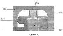
- FIG 2 is a magnified example of a connection member 125 inside of an adapter member 110 utilizing a crush rib 105.
- crush rib 105 is located at the end of an abuse protection rib 115.
- Crush rib 105 fits into adapter member 110 at the adapter member opening 120.
- the crush rib 105 prevents vibration of the connection member 125, more material continues to be removed from the crush rib 105.
- the connection member 125 may no longer have a tight fit within the adapter member opening's 120 inner walls.
- the control housing may lose its tight fit in the adapter member opening over time with use of the crush rib.
- the loss of the tight fit may be due to the constant vibration slowly removing additional material from the crush ribs over time. As more material is removed from the crush rib, the control housing may come loose from the adapter member opening and may result in rattle.
- a flex rib that may not be subject to material removal and therefore maintains vibration resistance over a longer period of time.
- a flex rib may be used on any connection or attachment member to provide a tight, vibration resistant fit of that member.
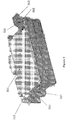
- Figure 3 is an example of a housing used for housing a control module for controlling a device configured to be repositioned.
- Figure 3 illustrates control housing 301 with connection members 310 and 315.
- Connection member 310 has a dog-leg configuration, allowing the connection member 310 to be hooked into an adapter member opening.
- Connection member 315 has a snap configuration, allowing the connection member 315 to swing into position and snap into the adaptor member opening.
- the connection members 310 and 315 may be integral with the control housing 301. For example, they may be formed of the same material at the same time by the same process.
- Connection member 310 and 315 may include a flex rib 305 and an abuse protection rib 320.
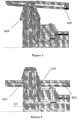
- FIG 4 is a magnified view of connection member 315.
- Figure 4 shows connection member 315 which includes flex rib 305 and abuse protection rib 320.
- Flex rib 305 includes a lead-in surface 430.
- the lead-in surface 430 allows for the connection member 315 to easily fit within an adapter member opening.
- Figures 5-8 illustrate instances of progress for the single motion of attaching the housing to an adapter member.
- Figure 5 is an example of a first instance of progress for the single motion of attaching the control housing 301 to an adapter member 505.
- Figure 5 illustrates that connection member 310 is first hooked into adapter member 505. Once connection member 310 is hooked into adapter member 505 at adapter member opening 510(a), control housing 301 is then pivoted on connection member 310, allowing connection member 315 to swing into position.
- Figure 6 is an example of a second instance of progress for the single motion of attaching the control housing 301 to the adapter member 505.
- Figure 6 illustrates adapter member 505 with adapter member opening 510 (b).
- the adapter member 505 is first contacting connection member 315.
- Connection member 315 includes a snap arm 620, a flex rib 305, and a flex rib lead-in surface 430.
- Figure 7 is an example of a third instance of progress for the single motion of attaching the control housing 301 to the adapter member 505.
- Figure 7 illustrates snap arm 620 flexing to allow the adapter member 505 to pass.
- Figure 8 is an example of a fourth and final instance of progress for the single motion of attaching the control housing 301 to the adapter member 505.
- Figure 8 illustrates snap arm 620 engaged with adapter member 505.
- the snap arm 620 retains control housing 301 vertically within adapter member 505.
- Flex ribs 305 resist transverse movement and vibration.
- Figure 9 is an example of a connection member 315 inside of an adapter member 505 utilizing flex ribs 305 and abuse protection ribs 320.
- Connection member 315 fits inside adapter member 505 at adapter member opening 510(b).
- Flex ribs 305 and abuse protection ribs 320 are located at the top and bottom of connection member 315. Flex ribs 305 and abuse protection ribs 320 are also located on the left side of connection member 315.
- connection member 315 is shown engaged within the adapter member opening 510(b).
- the flex ribs 305 are shown flexed within the adapter member opening 510(b).
- the designed interference, in-between the flex ribs 305 and the adapter member opening 510(b), may displace the ribs. This displacement may result in a constant feedback force acting against the adapter member opening's 510(b) inner walls.
- the constant feedback force may resist displacement of the connection member 315 in an environment susceptible to vibration and also absorb shock and reduce its transmission to any shock sensitive components.
- the abuse protection rib 320 is designed with clearance in-between it and the adapted member opening 510(b) wall. The abuse protection rib 320 may prevent excessive force from displacing the connection member 315 to a point of damaging the flex ribs 305.
- Figure 10 is a magnified view of Figure 9 .
- Flex ribs 305 and abuse protection ribs 320 provide a tight fit for connection member 315 in adapter member opening 510(b).
- Figure 10 shows the flex ribs 305 flexed within the adapter member opening 510(b). The designed interference displaces the flex ribs 305. This displacement results in a constant feedback force acting against the adapter member opening's 510(b) inner walls.
- the abuse protection rib 320 may prevent excessive force from displacing the connection member 315 to a point of damaging the flex ribs 305.
- Figure 11 is a top view example of a control housing 301 utilizing a flex rib 305.
- Flex rib 305 is a part of connection member 315.
- Detail A 1100 includes both flex rib 305 and abuse protection rib 320.
- Connection member 315 is part of control housing 301.
- the connection member 315, control housing 301, flex rib 305, and abuse protection rib 320 may be one piece.
- the connection member 315, control housing 301, flex rib 305, and abuse protection rib 320 may be a plastic, for example, polypropylene.
- the flex rib 305 is designed to be flexible and may be displaced with a reasonable amount of force.
- the abuse protection rib 320 may be used to limit the amount of deflection the flex rib 305 may be displaced.
- the flex rib 305 includes a lead-in surface to guide the flex rib 305 into an adapter member opening 510(b), allowing the flex rib 305 to be deflected automatically upon insertion.
- the flex rib 305 may provide dampening and may minimize movement of a control housing 301 when mounted to a vehicle. By dampening vibrations, electronics, connectors, and other devices are better protected from potential damage of loosening during vehicle operation. In addition, dampening vibrations helps reduce vehicle noise to benefit comfort of passengers within the vehicle.
- FIG 12 is a magnified view of Detail A 1100 in Figure 11 .
- Detail A 1100 includes flex rib 305 and abuse protection rib 320.
- the abuse protection rib 320 has a certain height which is less than that of the flex rib 305. This differential in height allows the flex rib 305 to flex all the way to the height of the abuse protection rib 320. This limits the amount of deflection the flex rib 305 may be displaced.
- Figure 13 is a flow diagram of an example method 1300 for connecting a housing unit for an electronics module to an adapter member.
- the method 1300 includes providing a housing with a first connection member and a second connection member 1305.
- the first connection member may include a flex rib and an abuse protection rib.
- the method 1300 may further include attaching the first connection member to an adapter member 1310.
- the method 1300 may further include pivoting the housing on the first connection member to allow the second connection member to swing into position 1315.
- the method 1300 may further include snapping the second connection member into the adapter member at an adapter member opening 1320.
Landscapes
- Engineering & Computer Science (AREA)
- Architecture (AREA)
- Civil Engineering (AREA)
- Structural Engineering (AREA)
- Microelectronics & Electronic Packaging (AREA)
- Connector Housings Or Holding Contact Members (AREA)
- Casings For Electric Apparatus (AREA)
- Details Of Connecting Devices For Male And Female Coupling (AREA)
Claims (14)
- Gehäuseeinheit für ein Elektronikmodul, wobei die Gehäuseeinheit umfasst:ein Gehäuse (301), das zum Sichern von Elektronik eines Elektronikmoduls gestaltet ist;ein Verbindungselement (310), das auf einer Seite des Gehäuses angeordnet ist;eine biegsame Rippe (305), die an dem Verbindungselement befestigt ist; undeine Missbrauchsschutzrippe (320), die mit dem Verbindungselement verbunden ist,dadurch gekennzeichnet, dassdie biegsame Rippe gestaltet ist, so dass sie beim Einsetzen abgelenkt wird, und wobei eine Höhe der Missbrauchsschutzrippe (320) geringer ist als eine Höhe der biegsamen Rippe (305), so dass die Höhe der Missbrauchsschutzrippe das Ausmaß einer Ablenkung der biegsamen Rippe begrenzt.
- Gehäuseeinheit nach Anspruch 1, wobei die biegsame Rippe (305) eine Einlauffläche (430) einschließt, um die biegsame Rippe in die Öffnung eines Adapterelements zu führen.
- Gehäuseeinheit nach Anspruch 1, wobei die biegsame Rippe (305) mit einem akzeptablen Kraftaufwand verschoben wird.
- Gehäuseeinheit nach Anspruch 3, wobei die Verschiebung der biegsamen Rippe (305) eine Rückwirkungskraft zur Folge hat, die einer Verschiebung des Verbindungselements in einer Öffnung des Adapterelements (510) Widerstand entgegensetzt.
- Gehäuseeinheit nach Anspruch 4, wobei die flexible Rippe (305) verhindert, dass das Verbindungselement in der Öffnung des Adapterelements klappert.
- Gehäuseeinheit nach Anspruch 1, wobei das Gehäuse (301), das Verbindungselement (315), die biegsame Rippe (305) und die Missbrauchsschutzrippe (320) ein Stück sind.
- Gehäuseeinheit nach Anspruch 1, wobei das Gehäuse (301), das Verbindungselement (315), die biegsame Rippe (305) und die Missbrauchsschutzrippe (320) aus Kunststoff bestehen.
- Verfahren zur Verbindung einer Gehäuseeinheit für ein Elektronikmodul mit einem Adapterelement, wobei das Verfahren umfasst:Bereitstellen eines Gehäuses mit einem ersten Verbindungselement und einem zweiten Verbindungselement, wobei das erste Verbindungselement eine biegsame Rippe und eine Missbrauchsschutzrippe enthält, die biegsame Rippe gestaltet ist, so dass sie beim Einsetzen abgelenkt wird;Befestigen des ersten Verbindungselements an einem Adapterelement;Schwenken des Gehäuses auf dem ersten Verbindungselement, so dass das zweite Verbindungselement in Position schwenken kann;Einrasten des zweiten Verbindungselements in das Adapterelement an einer Öffnung des Adapterelements; undBegrenzen einer Ablenkungsgröße der biegsamen Rippe mit der Missbrauchsschutzrippe.
- Verfahren nach Anspruch 8, wobei die biegsame Rippe eine Einlauffläche enthält, um die biegsame Rippe in die Öffnung des Adapterelements zu führen.
- Verfahren nach Anspruch 8, wobei die biegsame Rippe mit einem akzeptablen Kraftaufwand verschoben wird.
- Verfahren nach Anspruch 10, wobei die Verschiebung der biegsamen Rippe eine Einlegekraft zur Folge hat, die einer Verschiebung des Verbindungselements in der Öffnung des Adapterelements Widerstand entgegensetzt.
- Verfahren nach Anspruch 11, wobei die biegsame Rippe verhindert, dass das Verbindungselement in der Öffnung des Adapterelements klappert.
- Verfahren nach Anspruch 8, wobei das Gehäuse, das Verbindungselement, die biegsame Rippe und die Missbrauchsschutzrippe ein Stück sind.
- Verfahren nach Anspruch 8, wobei das Gehäuse, das Verbindungselement, die biegsame Rippe und die Missbrauchsschutzrippe aus Kunststoff bestehen.
Applications Claiming Priority (2)
| Application Number | Priority Date | Filing Date | Title |
|---|---|---|---|
| US13/601,055 US8723035B2 (en) | 2012-08-31 | 2012-08-31 | Vibration reduction rib |
| PCT/US2013/056993 WO2014036087A1 (en) | 2012-08-31 | 2013-08-28 | Vibration reduction rib |
Publications (2)
| Publication Number | Publication Date |
|---|---|
| EP2891394A1 EP2891394A1 (de) | 2015-07-08 |
| EP2891394B1 true EP2891394B1 (de) | 2018-05-02 |
Family
ID=49162242
Family Applications (1)
| Application Number | Title | Priority Date | Filing Date |
|---|---|---|---|
| EP13760183.7A Not-in-force EP2891394B1 (de) | 2012-08-31 | 2013-08-28 | Schwingungsreduktionsrippe |
Country Status (5)
| Country | Link |
|---|---|
| US (1) | US8723035B2 (de) |
| EP (1) | EP2891394B1 (de) |
| CN (1) | CN104782240B (de) |
| ES (1) | ES2674794T3 (de) |
| WO (1) | WO2014036087A1 (de) |
Families Citing this family (5)
| Publication number | Priority date | Publication date | Assignee | Title |
|---|---|---|---|---|
| FR3001603B1 (fr) * | 2013-01-29 | 2015-03-20 | Airbus Operations Sas | Carte electronique pour equipement avionique comprenant des moyens amortisseurs de vibrations entre son cadre de renfort et ses moyens de maintien |
| DE202017001367U1 (de) | 2016-03-14 | 2017-05-05 | Continental Automotive Gmbh | Blechgehäuse für eine elektronische Steuereinheit |
| EP3305610B1 (de) * | 2016-10-10 | 2020-12-16 | WABCO Europe BVBA | Elektronische steuereinheit für fahrzeuge, insbesondere für nutzfahrzeuge |
| US11142147B2 (en) * | 2019-06-28 | 2021-10-12 | Sumitomo Wiring Systems, Ltd. | Power distribution box assembly for a vehicle |
| USD1121561S1 (en) * | 2023-09-27 | 2026-04-07 | Bizlink Industry Germany Gmbh | Base plate |
Family Cites Families (12)
| Publication number | Priority date | Publication date | Assignee | Title |
|---|---|---|---|---|
| US5950973A (en) * | 1997-04-21 | 1999-09-14 | Delco Electronics | Housing mounting system |
| US6126458A (en) * | 1999-07-13 | 2000-10-03 | Yazaki North America, Inc. | Bussed electrical center assembly with connector pre-set |
| US6441304B1 (en) * | 2000-05-05 | 2002-08-27 | The Wiremold Company | Electrical outlet assembly |
| ES2169697B1 (es) * | 2000-11-03 | 2003-11-01 | Lear Automotive Eeds Spain | Dispositivo perfeccionado para fijacion de cajas de distribucion. |
| US6570088B1 (en) * | 2002-03-13 | 2003-05-27 | Sumitomo Wiring Systems, Ltd. | Junction box assembly |
| DE10235339A1 (de) * | 2002-08-02 | 2004-02-12 | Robert Bosch Gmbh | Befestigungsvorrichtung |
| JP2005042770A (ja) * | 2003-07-24 | 2005-02-17 | Sumitomo Wiring Syst Ltd | クランプの係止構造 |
| JP2007068377A (ja) * | 2005-09-02 | 2007-03-15 | Yazaki Corp | 電気接続箱 |
| DE102006027751A1 (de) * | 2006-06-16 | 2007-12-20 | Robert Bosch Gmbh | Befestigungselement zur Befestigung und/oder Vorfixierung eines Bauteils an einer mit einer Öffnung versehenen Halterung sowie Bauteil mit Befestigungselement |
| JP4858075B2 (ja) * | 2006-10-20 | 2012-01-18 | 住友電装株式会社 | 車載用の電気接続箱 |
| JP5088811B2 (ja) * | 2007-01-10 | 2012-12-05 | 矢崎総業株式会社 | 電気接続箱 |
| US7718892B2 (en) * | 2007-04-06 | 2010-05-18 | Flextronics Automotive Inc. | Control module housing |
-
2012
- 2012-08-31 US US13/601,055 patent/US8723035B2/en active Active
-
2013
- 2013-08-28 EP EP13760183.7A patent/EP2891394B1/de not_active Not-in-force
- 2013-08-28 WO PCT/US2013/056993 patent/WO2014036087A1/en not_active Ceased
- 2013-08-28 CN CN201380054718.2A patent/CN104782240B/zh active Active
- 2013-08-28 ES ES13760183.7T patent/ES2674794T3/es active Active
Non-Patent Citations (1)
| Title |
|---|
| None * |
Also Published As
| Publication number | Publication date |
|---|---|
| US20140062271A1 (en) | 2014-03-06 |
| CN104782240B (zh) | 2016-11-02 |
| ES2674794T3 (es) | 2018-07-04 |
| EP2891394A1 (de) | 2015-07-08 |
| US8723035B2 (en) | 2014-05-13 |
| CN104782240A (zh) | 2015-07-15 |
| WO2014036087A1 (en) | 2014-03-06 |
Similar Documents
| Publication | Publication Date | Title |
|---|---|---|
| EP2891394B1 (de) | Schwingungsreduktionsrippe | |
| US7718892B2 (en) | Control module housing | |
| US20150113773A1 (en) | Clip mounting seats of interior components or exterior components | |
| US7540749B1 (en) | Connector assemblies and systems | |
| US8654525B2 (en) | Clips and latch to receive a computing component | |
| CN113544016A (zh) | 安装架组件 | |
| CN105711534B (zh) | 用于安全气囊滑槽到安全气囊模块的防震接口 | |
| CN104284564A (zh) | 包括风扇马达的振动抑制机构的风扇罩和马达驱动装置 | |
| WO2018179262A1 (ja) | 車両用電子制御装置 | |
| EP2058723B1 (de) | Stossdämpfungsstruktur einer computerspeichervorrichtung | |
| CN203640451U (zh) | 一种汽车背门锁销总成 | |
| JP2009061959A (ja) | 弾性体の取付構造 | |
| US10215207B2 (en) | Support member | |
| US9564698B2 (en) | Capacitor frame assembly | |
| JP5821682B2 (ja) | 電装部品のガタツキ防止構造 | |
| EP3148846A1 (de) | Konsolenanordnung | |
| US7909627B2 (en) | Multi-axis retention mechanism | |
| CN110015335B (zh) | 转向设备 | |
| WO2022181802A1 (ja) | 車両用外装部品 | |
| WO2021046093A1 (en) | Double hook snap fit for electronic housing | |
| JP7113780B2 (ja) | 車載電子機器 | |
| CN220753074U (zh) | 车载硬盘盒和车载硬盘系统 | |
| JP5760805B2 (ja) | 車両用プロテクタ | |
| JP5083693B2 (ja) | 直方体状物体ホルダ用のコーナーユニット及び直方体状物体ホルダ | |
| JP2021018168A (ja) | 電子装置 |
Legal Events
| Date | Code | Title | Description |
|---|---|---|---|
| PUAI | Public reference made under article 153(3) epc to a published international application that has entered the european phase |
Free format text: ORIGINAL CODE: 0009012 |
|
| 17P | Request for examination filed |
Effective date: 20150326 |
|
| AK | Designated contracting states |
Kind code of ref document: A1 Designated state(s): AL AT BE BG CH CY CZ DE DK EE ES FI FR GB GR HR HU IE IS IT LI LT LU LV MC MK MT NL NO PL PT RO RS SE SI SK SM TR |
|
| AX | Request for extension of the european patent |
Extension state: BA ME |
|
| DAX | Request for extension of the european patent (deleted) | ||
| GRAP | Despatch of communication of intention to grant a patent |
Free format text: ORIGINAL CODE: EPIDOSNIGR1 |
|
| INTG | Intention to grant announced |
Effective date: 20171127 |
|
| GRAS | Grant fee paid |
Free format text: ORIGINAL CODE: EPIDOSNIGR3 |
|
| GRAA | (expected) grant |
Free format text: ORIGINAL CODE: 0009210 |
|
| AK | Designated contracting states |
Kind code of ref document: B1 Designated state(s): AL AT BE BG CH CY CZ DE DK EE ES FI FR GB GR HR HU IE IS IT LI LT LU LV MC MK MT NL NO PL PT RO RS SE SI SK SM TR |
|
| REG | Reference to a national code |
Ref country code: GB Ref legal event code: FG4D |
|
| REG | Reference to a national code |
Ref country code: CH Ref legal event code: EP Ref country code: AT Ref legal event code: REF Ref document number: 996625 Country of ref document: AT Kind code of ref document: T Effective date: 20180515 |
|
| REG | Reference to a national code |
Ref country code: DE Ref legal event code: R096 Ref document number: 602013036913 Country of ref document: DE Ref country code: IE Ref legal event code: FG4D |
|
| REG | Reference to a national code |
Ref country code: ES Ref legal event code: FG2A Ref document number: 2674794 Country of ref document: ES Kind code of ref document: T3 Effective date: 20180704 |
|
| RAP2 | Party data changed (patent owner data changed or rights of a patent transferred) |
Owner name: FLEXTRONICS AP, LLC |
|
| REG | Reference to a national code |
Ref country code: FR Ref legal event code: PLFP Year of fee payment: 6 |
|
| REG | Reference to a national code |
Ref country code: NL Ref legal event code: MP Effective date: 20180502 |
|
| REG | Reference to a national code |
Ref country code: LT Ref legal event code: MG4D |
|
| PG25 | Lapsed in a contracting state [announced via postgrant information from national office to epo] |
Ref country code: NO Free format text: LAPSE BECAUSE OF FAILURE TO SUBMIT A TRANSLATION OF THE DESCRIPTION OR TO PAY THE FEE WITHIN THE PRESCRIBED TIME-LIMIT Effective date: 20180802 Ref country code: SE Free format text: LAPSE BECAUSE OF FAILURE TO SUBMIT A TRANSLATION OF THE DESCRIPTION OR TO PAY THE FEE WITHIN THE PRESCRIBED TIME-LIMIT Effective date: 20180502 Ref country code: FI Free format text: LAPSE BECAUSE OF FAILURE TO SUBMIT A TRANSLATION OF THE DESCRIPTION OR TO PAY THE FEE WITHIN THE PRESCRIBED TIME-LIMIT Effective date: 20180502 Ref country code: BG Free format text: LAPSE BECAUSE OF FAILURE TO SUBMIT A TRANSLATION OF THE DESCRIPTION OR TO PAY THE FEE WITHIN THE PRESCRIBED TIME-LIMIT Effective date: 20180802 Ref country code: LT Free format text: LAPSE BECAUSE OF FAILURE TO SUBMIT A TRANSLATION OF THE DESCRIPTION OR TO PAY THE FEE WITHIN THE PRESCRIBED TIME-LIMIT Effective date: 20180502 |
|
| PG25 | Lapsed in a contracting state [announced via postgrant information from national office to epo] |
Ref country code: NL Free format text: LAPSE BECAUSE OF FAILURE TO SUBMIT A TRANSLATION OF THE DESCRIPTION OR TO PAY THE FEE WITHIN THE PRESCRIBED TIME-LIMIT Effective date: 20180502 Ref country code: RS Free format text: LAPSE BECAUSE OF FAILURE TO SUBMIT A TRANSLATION OF THE DESCRIPTION OR TO PAY THE FEE WITHIN THE PRESCRIBED TIME-LIMIT Effective date: 20180502 Ref country code: HR Free format text: LAPSE BECAUSE OF FAILURE TO SUBMIT A TRANSLATION OF THE DESCRIPTION OR TO PAY THE FEE WITHIN THE PRESCRIBED TIME-LIMIT Effective date: 20180502 Ref country code: GR Free format text: LAPSE BECAUSE OF FAILURE TO SUBMIT A TRANSLATION OF THE DESCRIPTION OR TO PAY THE FEE WITHIN THE PRESCRIBED TIME-LIMIT Effective date: 20180803 Ref country code: LV Free format text: LAPSE BECAUSE OF FAILURE TO SUBMIT A TRANSLATION OF THE DESCRIPTION OR TO PAY THE FEE WITHIN THE PRESCRIBED TIME-LIMIT Effective date: 20180502 |
|
| REG | Reference to a national code |
Ref country code: AT Ref legal event code: MK05 Ref document number: 996625 Country of ref document: AT Kind code of ref document: T Effective date: 20180502 |
|
| PG25 | Lapsed in a contracting state [announced via postgrant information from national office to epo] |
Ref country code: CZ Free format text: LAPSE BECAUSE OF FAILURE TO SUBMIT A TRANSLATION OF THE DESCRIPTION OR TO PAY THE FEE WITHIN THE PRESCRIBED TIME-LIMIT Effective date: 20180502 Ref country code: RO Free format text: LAPSE BECAUSE OF FAILURE TO SUBMIT A TRANSLATION OF THE DESCRIPTION OR TO PAY THE FEE WITHIN THE PRESCRIBED TIME-LIMIT Effective date: 20180502 Ref country code: DK Free format text: LAPSE BECAUSE OF FAILURE TO SUBMIT A TRANSLATION OF THE DESCRIPTION OR TO PAY THE FEE WITHIN THE PRESCRIBED TIME-LIMIT Effective date: 20180502 Ref country code: EE Free format text: LAPSE BECAUSE OF FAILURE TO SUBMIT A TRANSLATION OF THE DESCRIPTION OR TO PAY THE FEE WITHIN THE PRESCRIBED TIME-LIMIT Effective date: 20180502 Ref country code: AT Free format text: LAPSE BECAUSE OF FAILURE TO SUBMIT A TRANSLATION OF THE DESCRIPTION OR TO PAY THE FEE WITHIN THE PRESCRIBED TIME-LIMIT Effective date: 20180502 Ref country code: SK Free format text: LAPSE BECAUSE OF FAILURE TO SUBMIT A TRANSLATION OF THE DESCRIPTION OR TO PAY THE FEE WITHIN THE PRESCRIBED TIME-LIMIT Effective date: 20180502 Ref country code: PL Free format text: LAPSE BECAUSE OF FAILURE TO SUBMIT A TRANSLATION OF THE DESCRIPTION OR TO PAY THE FEE WITHIN THE PRESCRIBED TIME-LIMIT Effective date: 20180502 |
|
| REG | Reference to a national code |
Ref country code: DE Ref legal event code: R097 Ref document number: 602013036913 Country of ref document: DE |
|
| PG25 | Lapsed in a contracting state [announced via postgrant information from national office to epo] |
Ref country code: SM Free format text: LAPSE BECAUSE OF FAILURE TO SUBMIT A TRANSLATION OF THE DESCRIPTION OR TO PAY THE FEE WITHIN THE PRESCRIBED TIME-LIMIT Effective date: 20180502 |
|
| PLBE | No opposition filed within time limit |
Free format text: ORIGINAL CODE: 0009261 |
|
| STAA | Information on the status of an ep patent application or granted ep patent |
Free format text: STATUS: NO OPPOSITION FILED WITHIN TIME LIMIT |
|
| PG25 | Lapsed in a contracting state [announced via postgrant information from national office to epo] |
Ref country code: MC Free format text: LAPSE BECAUSE OF FAILURE TO SUBMIT A TRANSLATION OF THE DESCRIPTION OR TO PAY THE FEE WITHIN THE PRESCRIBED TIME-LIMIT Effective date: 20180502 |
|
| REG | Reference to a national code |
Ref country code: CH Ref legal event code: PL |
|
| 26N | No opposition filed |
Effective date: 20190205 |
|
| PG25 | Lapsed in a contracting state [announced via postgrant information from national office to epo] |
Ref country code: CH Free format text: LAPSE BECAUSE OF NON-PAYMENT OF DUE FEES Effective date: 20180831 Ref country code: LI Free format text: LAPSE BECAUSE OF NON-PAYMENT OF DUE FEES Effective date: 20180831 Ref country code: LU Free format text: LAPSE BECAUSE OF NON-PAYMENT OF DUE FEES Effective date: 20180828 |
|
| REG | Reference to a national code |
Ref country code: BE Ref legal event code: MM Effective date: 20180831 |
|
| PG25 | Lapsed in a contracting state [announced via postgrant information from national office to epo] |
Ref country code: SI Free format text: LAPSE BECAUSE OF FAILURE TO SUBMIT A TRANSLATION OF THE DESCRIPTION OR TO PAY THE FEE WITHIN THE PRESCRIBED TIME-LIMIT Effective date: 20180502 |
|
| PG25 | Lapsed in a contracting state [announced via postgrant information from national office to epo] |
Ref country code: BE Free format text: LAPSE BECAUSE OF NON-PAYMENT OF DUE FEES Effective date: 20180831 |
|
| PG25 | Lapsed in a contracting state [announced via postgrant information from national office to epo] |
Ref country code: AL Free format text: LAPSE BECAUSE OF FAILURE TO SUBMIT A TRANSLATION OF THE DESCRIPTION OR TO PAY THE FEE WITHIN THE PRESCRIBED TIME-LIMIT Effective date: 20180502 |
|
| PG25 | Lapsed in a contracting state [announced via postgrant information from national office to epo] |
Ref country code: MT Free format text: LAPSE BECAUSE OF NON-PAYMENT OF DUE FEES Effective date: 20180828 |
|
| PG25 | Lapsed in a contracting state [announced via postgrant information from national office to epo] |
Ref country code: TR Free format text: LAPSE BECAUSE OF FAILURE TO SUBMIT A TRANSLATION OF THE DESCRIPTION OR TO PAY THE FEE WITHIN THE PRESCRIBED TIME-LIMIT Effective date: 20180502 |
|
| PG25 | Lapsed in a contracting state [announced via postgrant information from national office to epo] |
Ref country code: PT Free format text: LAPSE BECAUSE OF FAILURE TO SUBMIT A TRANSLATION OF THE DESCRIPTION OR TO PAY THE FEE WITHIN THE PRESCRIBED TIME-LIMIT Effective date: 20180502 |
|
| PG25 | Lapsed in a contracting state [announced via postgrant information from national office to epo] |
Ref country code: CY Free format text: LAPSE BECAUSE OF FAILURE TO SUBMIT A TRANSLATION OF THE DESCRIPTION OR TO PAY THE FEE WITHIN THE PRESCRIBED TIME-LIMIT Effective date: 20180502 Ref country code: IE Free format text: LAPSE BECAUSE OF NON-PAYMENT OF DUE FEES Effective date: 20180828 Ref country code: HU Free format text: LAPSE BECAUSE OF FAILURE TO SUBMIT A TRANSLATION OF THE DESCRIPTION OR TO PAY THE FEE WITHIN THE PRESCRIBED TIME-LIMIT; INVALID AB INITIO Effective date: 20130828 Ref country code: MK Free format text: LAPSE BECAUSE OF NON-PAYMENT OF DUE FEES Effective date: 20180502 |
|
| PG25 | Lapsed in a contracting state [announced via postgrant information from national office to epo] |
Ref country code: IS Free format text: LAPSE BECAUSE OF FAILURE TO SUBMIT A TRANSLATION OF THE DESCRIPTION OR TO PAY THE FEE WITHIN THE PRESCRIBED TIME-LIMIT Effective date: 20180902 |
|
| PGFP | Annual fee paid to national office [announced via postgrant information from national office to epo] |
Ref country code: IT Payment date: 20230822 Year of fee payment: 11 Ref country code: GB Payment date: 20230822 Year of fee payment: 11 Ref country code: ES Payment date: 20230914 Year of fee payment: 11 |
|
| PGFP | Annual fee paid to national office [announced via postgrant information from national office to epo] |
Ref country code: FR Payment date: 20230824 Year of fee payment: 11 Ref country code: DE Payment date: 20230828 Year of fee payment: 11 |
|
| REG | Reference to a national code |
Ref country code: DE Ref legal event code: R119 Ref document number: 602013036913 Country of ref document: DE |
|
| GBPC | Gb: european patent ceased through non-payment of renewal fee |
Effective date: 20240828 |
|
| PG25 | Lapsed in a contracting state [announced via postgrant information from national office to epo] |
Ref country code: DE Free format text: LAPSE BECAUSE OF NON-PAYMENT OF DUE FEES Effective date: 20250301 |
|
| PG25 | Lapsed in a contracting state [announced via postgrant information from national office to epo] |
Ref country code: GB Free format text: LAPSE BECAUSE OF NON-PAYMENT OF DUE FEES Effective date: 20240828 |
|
| PG25 | Lapsed in a contracting state [announced via postgrant information from national office to epo] |
Ref country code: IT Free format text: LAPSE BECAUSE OF NON-PAYMENT OF DUE FEES Effective date: 20240828 |
|
| PG25 | Lapsed in a contracting state [announced via postgrant information from national office to epo] |
Ref country code: FR Free format text: LAPSE BECAUSE OF NON-PAYMENT OF DUE FEES Effective date: 20240831 |
|
| REG | Reference to a national code |
Ref country code: ES Ref legal event code: FD2A Effective date: 20251003 |
|
| PG25 | Lapsed in a contracting state [announced via postgrant information from national office to epo] |
Ref country code: ES Free format text: LAPSE BECAUSE OF NON-PAYMENT OF DUE FEES Effective date: 20240829 |