EP2058723B1 - Stossdämpfungsstruktur einer computerspeichervorrichtung - Google Patents
Stossdämpfungsstruktur einer computerspeichervorrichtung Download PDFInfo
- Publication number
- EP2058723B1 EP2058723B1 EP08008362.9A EP08008362A EP2058723B1 EP 2058723 B1 EP2058723 B1 EP 2058723B1 EP 08008362 A EP08008362 A EP 08008362A EP 2058723 B1 EP2058723 B1 EP 2058723B1
- Authority
- EP
- European Patent Office
- Prior art keywords
- shock absorbing
- storage device
- base
- frame
- computer
- Prior art date
- Legal status (The legal status is an assumption and is not a legal conclusion. Google has not performed a legal analysis and makes no representation as to the accuracy of the status listed.)
- Not-in-force
Links
Images

Classifications
-
- G—PHYSICS
- G06—COMPUTING OR CALCULATING; COUNTING
- G06F—ELECTRIC DIGITAL DATA PROCESSING
- G06F1/00—Details not covered by groups G06F3/00 - G06F13/00 and G06F21/00
- G06F1/16—Constructional details or arrangements
- G06F1/18—Packaging or power distribution
- G06F1/183—Internal mounting support structures, e.g. for supporting printed circuit boards
- G06F1/187—Mounting of fixed or removable disk drives
Definitions
- the present invention relates to a shock absorbing structure of a computer storage device, and more particularly to a shock absorbing structure capable of damping the energy transmitted to the storage device to achieve a better shock absorbing effect.
- computers are used extensively with a faster speed and a more diversified manner.
- computers are also installed in motor vehicles to provide information of the motor vehicle control system and control other automobile equipments such as stereo, CD drive and global positioning system (GPS) to provide additional information and recreation to drivers and passengers, and computer gradually becomes a standard equipment for motor vehicles.
- GPS global positioning system
- the hard disk drive is a dispensable part for storing and controlling an automobile performance program and integrating various automobile equipments. Since severe vibrations are usually produced in different road conditions when the car is traveling, the hard disk drive may be damaged, the computer operation may be affected, and even the safety may be jeopardized.
- the computer is usually installed at a position in the car with the least level of vibrations in accordance with the prior art to enhance the elastic strength of a computer structure.
- the major damage of the computer comes from the vibrations of the car body, and such vibrations directly affect the hard disk installed in the computer. Therefore, finding a way of improving the protection of hard disks installed in computers demands immediate attentions and feasible solutions for the structural design of the computer.
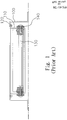
- the shock absorber includes a frame 100 mounted in a computer casing for hanging a rack 110 in the frame 100, and the rack 110 is secured in the frame 100 by screws 120, and the rack 110 is provided for fixing a hard disk 130, and an elastic pad 140 is installed between the hard disk 130 and the rack 110, and the hard disk 130 is installed on the elastic pad 140.
- vibrations produced when a car is traveling can be absorbed by the elastic pad 140, the elastic pad 140 cannot absorb severe vibrations completely, and the shock absorbing effect will be affected.
- EP1102278 discloses a mounting system for a disk drive for absorbing shock andvibration in a machining environment.
- the structure comprises a base and a frame, wherein the base includes a containing space for precisely containing a storage device (such as a hard disk drive or a CD drive), and the base has a protruding ear extended outwardly and separately from both lateral sides of the base, and upper and lower sides of each protruding ear have corresponding first and second shock absorbing elements made of materials with different elastic strengths respectively.
- a storage device such as a hard disk drive or a CD drive
- the second shock absorbing element is provided for maintaining an appropriate interval between the base and the computer chassis, wherein a frame uses the first shock absorbing element to hang the base below the frame, such that the different elastic strengths of the first and second shock absorbing elements cause different absorbing and feedback forces of the first and second shock absorbing elements to damp the energy transmitted to the storage device to improve the shock absorbing effect.
- Another objective of the present invention is to provide a shock absorbing structure of a computer storage device, wherein a pad member is installed between corresponding lateral sides of the frame and the base for increasing the shock resistance to improve the shock absorbing effect.
- a further objective of the present invention is to provide a shock absorbing structure of a computer storage device, wherein an elastic pad is embedded between both lateral sides of the base and fixed onto the storage device, such that if the storage device is installed, the vibration energy can be absorbed by the elastic pad to improve the shock absorbing effect.
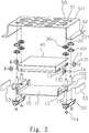
- the structure comprises a base 10 having a containing space 11 for containing a storage device 40 (which is a hard disk in this embodiment), and at least one open embedding hole 12 disposed separately on both lateral sides of containing space 11 for embedding an elastic pad 13 which is a wheel-shaped pad member.
- the elastic pad 13 has a through hole 131 extended axially along the elastic pad 13, and an embedding groove 132 disposed in the elastic pad 13, such that the embedding groove 132 can be embedded into the embedding hole 12 from an opening of the embedding hole 12 for embedding the elastic pad 13 into the embedding hole 12.
- a screw rod 14 is passed through the through hole 131 and secured separately onto both lateral sides of the storage device 40 in the containing space 11, so that the storage device 40 can be fixed into the containing space 11.
- the elastic pad 13 is provided for absorbing energy produced by the vibrations to achieve a better shock absorbing effect. If it is necessary to remove the storage device 40, the elastic pad 13 is pushed away from the embedding hole 12 to separate the storage device 40 from the base 10 in order to facilitate the removal of the storage device 40 for maintenance and repair.
- a plurality of protruding ears 15 are substantially C-shape frames in this embodiment and extended separately outward from both lateral sides of the base 10.
- a side of the protruding ear 15 includes at least one protruding locking hole 151 (wherein two locking holes 151 are adopted in this embodiment), and each protruding ear 15 includes a second shock absorbing element 20 (which is an oval spring plate) disposed below the corresponding locking hole 151, such that a screw rod 14 can be passed through the second shock absorbing element 20 and secured into the locking hole 151 for fixing the second shock absorbing element 20 below the base 10.
- the second shock absorbing element 20 maintains an appropriate interval between the base 10 and the computer chassis.
- Another side of the protruding ear 15 has at least one protruding pillar 152 (wherein two protruding pillars 152 are adopted in this embodiment) sheathed with at least one first shock absorbing element 30 corresponding to the second shock absorbing element 20 (and two disc-shaped pad members are adopted in this embodiment), and the first shock absorbing element 30 and the second shock absorbing element 20 come with different elastic strengths.
- the first shock absorbing element 30 is embedded into a frame 50 which is a U-shaped frame, and the frame 50 has one or more openings 51, each interconnected with the slide slot 511.
- the diameter of the slide slot 511 is smaller than the diameter of the opening 51, and thus the embedding groove 301 of the first shock absorbing element 30 can be slid from the opening 51 into the slide slot 511 and hanged in the frame 50, and the base 10 can be hanged in the frame 50 as well.
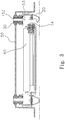
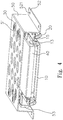
- An extended edge 52 is extended horizontally and separately along both lateral sides of the frame 50, and each extended edge 52 has a screw hole 521 for passing through a screw rod to fix the frame 50 at an appropriate position in the computer chassis (as shown in FIGS. 4 and 5 ), and a gap is formed between corresponding lateral sides of the frame 50 and the base 10 for plugging in a pad member 53 which is a sponge in this embodiment for damping the shocks.
- the first and second shock absorbing elements 30, 20 come with different elastic strengths for diversifying the energy produced by the vibrations and reducing the energy transmitted to the storage device 40, so as to improve the shock absorbing effect.
Landscapes
- Engineering & Computer Science (AREA)
- Theoretical Computer Science (AREA)
- Computer Hardware Design (AREA)
- Power Engineering (AREA)
- Human Computer Interaction (AREA)
- Physics & Mathematics (AREA)
- General Engineering & Computer Science (AREA)
- General Physics & Mathematics (AREA)
- Vibration Dampers (AREA)
- Vibration Prevention Devices (AREA)
- Fittings On The Vehicle Exterior For Carrying Loads, And Devices For Holding Or Mounting Articles (AREA)
Claims (7)
- Stoßdämpfungsstruktur einer Computerspeicher-Vorrichtung (40), die in einem Computer-Gehäuse angeordnet ist, umfassend eine Basis (10), die sich im dem Computer-Gehäuse befindet und einen Aufnahmeraum (11) aufweist, der die Speicher-Vorrichtung (40) enthält und fixiert: einen Rahmen (50), dessen Form im wesentlichen der eines Gestells entspricht, das auf der Basis (10) installiert ist, wobei der Rahmen (50) mit dem Computer-Gehäuse fest verbunden ist; ferner umfassend wenigstens ein erstes StoßdämpfungsElement (30), das in dem Rahmen (50) angeordnet und zwischen der Basis (10) und dem Rahmen (50) installiert ist, und dazu dient, die Basis (10) und den Rahmen (50) zu verbinden, wobei das erste Stoßdämpfungselement (30) ein scheibenförmiger Pufferkörper ist, der Rahmen (50) eine oder mehrere Öffnungen (51) aufweist, die jede mit einem Gleitschlitz (511) in Verbindung steht, der Durchmesser dieses Gleitschlitzes (511) kleiner ist als der Durchmesser der Öffnung (51), das erste Stoßdämpfungselement (30) mit einer Lagerungsnut (301) versehen ist, die von der Öffnung (51) in den Gleitschlitz (511) verschiebbar ist und in dem Rahmen (50) von der Basis (10) hängt und somit auch in dem Rahmen (50) hängt;
des weiteren mit wenigstens einem zweiten Stoßdämpfungselement (20), das mit der Basis (10) fest verbunden ist und zwischen der Basis (10) und dem Computer-Gehäuse installiert ist und dazu dient, zwischen der Basis (10) und dem Computer-Gehäuse einen geeigneten Zwischenraum aufrecht zu erhalten, wobei das zweite Stoßdämpfungselement (20) eine Elastizität aufweist, die sich von derjenigen des ersten Stoßdämpfungselementes (30) unterscheidet, und zwar derart, daß dann, wenn das Computer-Gehäuse schwingt, die unterschiedlichen Elastizitäten der ersten und zweiten Stoßdämpfungselemente (30, 20) eine Vibrationskraft umleiten, um die Energie, die auf die Speicher-Vorrichtung (40) übertragen wird, zu reduzieren und einen Stoßdämpfungseffekt zu erreichen. - Stoßdämpfungsstruktur einer Computerspeicher-Vorrichtung (40) nach Anspruch 1, dadurch gekennzeichnet, daß der Rahmen (50) so ausgebildet ist, daß er die Basis (10) enthält.
- Stoßdämpfungsstruktur einer Computerspeicher-Vorrichtung (40) nach Anspruch 1 oder 2, dadurch gekennzeichnet, daß die Basis (10) mehrere Einbettungslöcher (12) aufweist, die auf beiden lateralen Seiten der Basis (10) entsprechend angeordnet sind, sowie einen elastischen Puffer (13), der getrennt in den Einbettungslöchern (12) eingebettet ist und fest auf einer lateralen Seite der Speicher-Vorrichtung (40) angebracht ist, um die Stoßdämpfungswirkung zu verstärken, wobei der elastische Puffer (13) ein radförmiger Pufferkörper ist und ein Durchgangsloch (131) aufweist, das sich in axialer Richtung entlang des Puffers (13) erstreckt, und mit einer Einbettungsnut (132), die sich in dem elastischen Puffer (13) befindet, so daß die genannte Einbettungsnut (132) in dem Einbettungsloch (12) von einer Öffnung des Einbettungsloches (12) aus eingebettet wird, um dadurch den elastischen Puffer (13) in dem Einbettungsloch (12) anzuordnen, des weiteren mit einem Schraubbolzen (14), der durch das Durchgangsloch (131) gesteckt ist und separat auf beiden lateralen Seiten der Speicher-Vorrichtung (40) in dem Aufnahmeraum (11) befestigt ist, so daß die Speicher-Vorrichtung (40) in dem Aufnahmeraum (11) fixiert werden kann, und dann, wenn die Speicher-Vorrichtung (40) entfernt wird, der elastische Puffer (13) von dem Einbettungsloch (12) weggestoßen wird, um die Speicher-Vorrichtung (40) von der Basis (10) zu trennen und damit das Entfernen der Speicher-Vorrichtung (40) zu Wartungs- und Reparaturzwecken zu erleichtern.
- Stoßdämpfungsstruktur einer Computerspeicher-Vorrichtung (40) nach einem der Ansprüche 1 bis 3, dadurch gekennzeichnet, daß die Basis (10) mehrere vorspringende Ansätze (15) aufweist, die auf beiden lateralen Seiten der Basis (10) angeordnet sind und dazu dienen, die ersten und zweiten stoßdämpfenden Elemente (30, 20) auf den oberen und unteren Seiten der vorspringenden Ansätze (15) entsprechend zu installieren.
- Stoßdämpfungsstruktur einer Computerspeicher-Vorrichtung (40) nach Anspruch 4, gekennzeichnet durch einen Pufferkörper (53), der zwischen entsprechenden lateralen Seiten des Rahmens (50) und den vorspringenden Ansätzen (15) getrennt installiert ist.
- Stoßdämpfungsstruktur einer Computerspeicher-Vorrichtung (40) nach Anspruch 5, dadurch gekennzeichnet, daß der Pufferkörper (53) ein Schwamm ist.
- Stoßdämpfungsstruktur einer Computerspeicher-Vorrichtung (40) nach einem der vorhergehenden Ansprüche, dadurch gekennzeichnet, daß das zweite Stoßdämpfungselement (20) eine Federplatte ist.
Applications Claiming Priority (1)
| Application Number | Priority Date | Filing Date | Title |
|---|---|---|---|
| TW96218770U TWM332881U (en) | 2007-11-07 | 2007-11-07 | Shock absorbing structure for computer storage device |
Publications (3)
| Publication Number | Publication Date |
|---|---|
| EP2058723A2 EP2058723A2 (de) | 2009-05-13 |
| EP2058723A3 EP2058723A3 (de) | 2009-06-10 |
| EP2058723B1 true EP2058723B1 (de) | 2018-10-10 |
Family
ID=39553122
Family Applications (1)
| Application Number | Title | Priority Date | Filing Date |
|---|---|---|---|
| EP08008362.9A Not-in-force EP2058723B1 (de) | 2007-11-07 | 2008-05-02 | Stossdämpfungsstruktur einer computerspeichervorrichtung |
Country Status (2)
| Country | Link |
|---|---|
| EP (1) | EP2058723B1 (de) |
| TW (1) | TWM332881U (de) |
Families Citing this family (7)
| Publication number | Priority date | Publication date | Assignee | Title |
|---|---|---|---|---|
| TWI428080B (zh) * | 2009-07-10 | 2014-02-21 | Fih Hong Kong Ltd | 電子組件裝配結構 |
| CN102096443B (zh) * | 2010-12-13 | 2016-04-13 | 王一川 | 电脑机箱的减振消噪垫板 |
| CN102802368B (zh) * | 2011-05-24 | 2016-06-29 | 鸿富锦精密工业(深圳)有限公司 | 服务器机箱及服务器系统 |
| TWI438772B (zh) * | 2011-07-15 | 2014-05-21 | Pegatron Corp | 減振儲存模組 |
| CN111916117B (zh) * | 2019-05-10 | 2024-09-03 | 郑州精益达汽车零部件有限公司 | 消费级便携式存储硬盘车载减振器及其生产方法 |
| CN114063742B (zh) * | 2021-12-22 | 2023-11-21 | 研华科技(中国)有限公司 | 一种嵌入式工控机壳体 |
| CN120656505A (zh) * | 2025-06-16 | 2025-09-16 | 深圳市绿联科技股份有限公司 | 一种网络附加存储设备 |
Family Cites Families (3)
| Publication number | Priority date | Publication date | Assignee | Title |
|---|---|---|---|---|
| US6477042B1 (en) * | 1999-11-18 | 2002-11-05 | Siemens Energy & Automation, Inc. | Disk drive mounting system for absorbing shock and vibration in a machining environment |
| CN2542884Y (zh) * | 2002-04-17 | 2003-04-02 | 鸿富锦精密工业(深圳)有限公司 | 减震结构 |
| US7324337B2 (en) * | 2004-04-19 | 2008-01-29 | Jeffry Padin | Compact rugged computer system for mobile applications |
-
2007
- 2007-11-07 TW TW96218770U patent/TWM332881U/zh not_active IP Right Cessation
-
2008
- 2008-05-02 EP EP08008362.9A patent/EP2058723B1/de not_active Not-in-force
Non-Patent Citations (1)
| Title |
|---|
| None * |
Also Published As
| Publication number | Publication date |
|---|---|
| EP2058723A2 (de) | 2009-05-13 |
| TWM332881U (en) | 2008-05-21 |
| EP2058723A3 (de) | 2009-06-10 |
Similar Documents
| Publication | Publication Date | Title |
|---|---|---|
| EP2058723A2 (de) | Stoßdämpfungsstruktur einer Computerspeichervorrichtung | |
| KR100669287B1 (ko) | 차량용 하드디스크 드라이브 방진 장치 및 그 조립방법 | |
| US20130015317A1 (en) | Vibration Isolation Storage Module | |
| CN101048045B (zh) | 音频部件安装系统和用于吸收音频部件中的碰撞的方法 | |
| US20190056023A1 (en) | Structure of transmission mount | |
| CN204986027U (zh) | 一种轻型卡车及其管路夹持装置 | |
| EP3400393B1 (de) | Bremsrotor mit geneigten montageschlitzen | |
| CN210164828U (zh) | 车载减振系统及车载设备 | |
| CN211441893U (zh) | 车辆前减震器安装总成 | |
| CN215301101U (zh) | 一种具有抗振动性能的电动车控制器 | |
| TWI790502B (zh) | 承載組件 | |
| CN114510124B (zh) | 承载组件 | |
| JP2003341331A (ja) | サスペンション | |
| CN112822886B (zh) | 一种车载pcb电路板 | |
| CN210866283U (zh) | 一种电动车用减震电池盒 | |
| CN204733016U (zh) | 一种电机减振结构 | |
| EP4077053B1 (de) | System zur integration von lautsprecherboxen | |
| CN216009366U (zh) | 一种电池减震装置和车辆 | |
| KR101093991B1 (ko) | 하드디스크 드라이브의 방진 구조 | |
| CN2938205Y (zh) | 硬盘防震结构 | |
| KR20160050641A (ko) | 차량용 현가장치의 판스프링 마찰 방지구조 | |
| CN220974071U (zh) | 一种后视镜行车记录仪 | |
| TWI851095B (zh) | 移動載具及減震組件 | |
| CN220577449U (zh) | 减震装置、车架结构以及平衡车 | |
| JP6158371B2 (ja) | キャンバー調節用ピローボールマウント |
Legal Events
| Date | Code | Title | Description |
|---|---|---|---|
| PUAI | Public reference made under article 153(3) epc to a published international application that has entered the european phase |
Free format text: ORIGINAL CODE: 0009012 |
|
| PUAL | Search report despatched |
Free format text: ORIGINAL CODE: 0009013 |
|
| AK | Designated contracting states |
Kind code of ref document: A2 Designated state(s): AT BE BG CH CY CZ DE DK EE ES FI FR GB GR HR HU IE IS IT LI LT LU LV MC MT NL NO PL PT RO SE SI SK TR |
|
| AX | Request for extension of the european patent |
Extension state: AL BA MK RS |
|
| AK | Designated contracting states |
Kind code of ref document: A3 Designated state(s): AT BE BG CH CY CZ DE DK EE ES FI FR GB GR HR HU IE IS IT LI LT LU LV MC MT NL NO PL PT RO SE SI SK TR |
|
| AX | Request for extension of the european patent |
Extension state: AL BA MK RS |
|
| 17P | Request for examination filed |
Effective date: 20091207 |
|
| AKX | Designation fees paid |
Designated state(s): AT BE BG CH CY CZ DE DK EE ES FI FR GB GR HR HU IE IS IT LI LT LU LV MC MT NL NO PL PT RO SE SI SK TR |
|
| 17Q | First examination report despatched |
Effective date: 20100210 |
|
| STAA | Information on the status of an ep patent application or granted ep patent |
Free format text: STATUS: EXAMINATION IS IN PROGRESS |
|
| REG | Reference to a national code |
Ref country code: DE Ref legal event code: R079 Ref document number: 602008057309 Country of ref document: DE Free format text: PREVIOUS MAIN CLASS: G06F0001160000 Ipc: G06F0001180000 |
|
| RIC1 | Information provided on ipc code assigned before grant |
Ipc: G06F 1/18 20060101AFI20180313BHEP |
|
| GRAP | Despatch of communication of intention to grant a patent |
Free format text: ORIGINAL CODE: EPIDOSNIGR1 |
|
| STAA | Information on the status of an ep patent application or granted ep patent |
Free format text: STATUS: GRANT OF PATENT IS INTENDED |
|
| INTG | Intention to grant announced |
Effective date: 20180507 |
|
| GRAS | Grant fee paid |
Free format text: ORIGINAL CODE: EPIDOSNIGR3 |
|
| GRAA | (expected) grant |
Free format text: ORIGINAL CODE: 0009210 |
|
| STAA | Information on the status of an ep patent application or granted ep patent |
Free format text: STATUS: THE PATENT HAS BEEN GRANTED |
|
| AK | Designated contracting states |
Kind code of ref document: B1 Designated state(s): AT BE BG CH CY CZ DE DK EE ES FI FR GB GR HR HU IE IS IT LI LT LU LV MC MT NL NO PL PT RO SE SI SK TR |
|
| REG | Reference to a national code |
Ref country code: GB Ref legal event code: FG4D |
|
| REG | Reference to a national code |
Ref country code: CH Ref legal event code: EP Ref country code: AT Ref legal event code: REF Ref document number: 1051997 Country of ref document: AT Kind code of ref document: T Effective date: 20181015 |
|
| REG | Reference to a national code |
Ref country code: IE Ref legal event code: FG4D |
|
| REG | Reference to a national code |
Ref country code: DE Ref legal event code: R096 Ref document number: 602008057309 Country of ref document: DE |
|
| REG | Reference to a national code |
Ref country code: NL Ref legal event code: FP |
|
| REG | Reference to a national code |
Ref country code: LT Ref legal event code: MG4D |
|
| REG | Reference to a national code |
Ref country code: AT Ref legal event code: MK05 Ref document number: 1051997 Country of ref document: AT Kind code of ref document: T Effective date: 20181010 |
|
| PG25 | Lapsed in a contracting state [announced via postgrant information from national office to epo] |
Ref country code: ES Free format text: LAPSE BECAUSE OF FAILURE TO SUBMIT A TRANSLATION OF THE DESCRIPTION OR TO PAY THE FEE WITHIN THE PRESCRIBED TIME-LIMIT Effective date: 20181010 Ref country code: LV Free format text: LAPSE BECAUSE OF FAILURE TO SUBMIT A TRANSLATION OF THE DESCRIPTION OR TO PAY THE FEE WITHIN THE PRESCRIBED TIME-LIMIT Effective date: 20181010 Ref country code: NO Free format text: LAPSE BECAUSE OF FAILURE TO SUBMIT A TRANSLATION OF THE DESCRIPTION OR TO PAY THE FEE WITHIN THE PRESCRIBED TIME-LIMIT Effective date: 20190110 Ref country code: AT Free format text: LAPSE BECAUSE OF FAILURE TO SUBMIT A TRANSLATION OF THE DESCRIPTION OR TO PAY THE FEE WITHIN THE PRESCRIBED TIME-LIMIT Effective date: 20181010 Ref country code: IS Free format text: LAPSE BECAUSE OF FAILURE TO SUBMIT A TRANSLATION OF THE DESCRIPTION OR TO PAY THE FEE WITHIN THE PRESCRIBED TIME-LIMIT Effective date: 20190210 Ref country code: FI Free format text: LAPSE BECAUSE OF FAILURE TO SUBMIT A TRANSLATION OF THE DESCRIPTION OR TO PAY THE FEE WITHIN THE PRESCRIBED TIME-LIMIT Effective date: 20181010 Ref country code: HR Free format text: LAPSE BECAUSE OF FAILURE TO SUBMIT A TRANSLATION OF THE DESCRIPTION OR TO PAY THE FEE WITHIN THE PRESCRIBED TIME-LIMIT Effective date: 20181010 Ref country code: PL Free format text: LAPSE BECAUSE OF FAILURE TO SUBMIT A TRANSLATION OF THE DESCRIPTION OR TO PAY THE FEE WITHIN THE PRESCRIBED TIME-LIMIT Effective date: 20181010 Ref country code: LT Free format text: LAPSE BECAUSE OF FAILURE TO SUBMIT A TRANSLATION OF THE DESCRIPTION OR TO PAY THE FEE WITHIN THE PRESCRIBED TIME-LIMIT Effective date: 20181010 Ref country code: BG Free format text: LAPSE BECAUSE OF FAILURE TO SUBMIT A TRANSLATION OF THE DESCRIPTION OR TO PAY THE FEE WITHIN THE PRESCRIBED TIME-LIMIT Effective date: 20190110 |
|
| PG25 | Lapsed in a contracting state [announced via postgrant information from national office to epo] |
Ref country code: GR Free format text: LAPSE BECAUSE OF FAILURE TO SUBMIT A TRANSLATION OF THE DESCRIPTION OR TO PAY THE FEE WITHIN THE PRESCRIBED TIME-LIMIT Effective date: 20190111 Ref country code: SE Free format text: LAPSE BECAUSE OF FAILURE TO SUBMIT A TRANSLATION OF THE DESCRIPTION OR TO PAY THE FEE WITHIN THE PRESCRIBED TIME-LIMIT Effective date: 20181010 Ref country code: PT Free format text: LAPSE BECAUSE OF FAILURE TO SUBMIT A TRANSLATION OF THE DESCRIPTION OR TO PAY THE FEE WITHIN THE PRESCRIBED TIME-LIMIT Effective date: 20190210 |
|
| REG | Reference to a national code |
Ref country code: DE Ref legal event code: R097 Ref document number: 602008057309 Country of ref document: DE |
|
| PG25 | Lapsed in a contracting state [announced via postgrant information from national office to epo] |
Ref country code: CZ Free format text: LAPSE BECAUSE OF FAILURE TO SUBMIT A TRANSLATION OF THE DESCRIPTION OR TO PAY THE FEE WITHIN THE PRESCRIBED TIME-LIMIT Effective date: 20181010 Ref country code: DK Free format text: LAPSE BECAUSE OF FAILURE TO SUBMIT A TRANSLATION OF THE DESCRIPTION OR TO PAY THE FEE WITHIN THE PRESCRIBED TIME-LIMIT Effective date: 20181010 Ref country code: IT Free format text: LAPSE BECAUSE OF FAILURE TO SUBMIT A TRANSLATION OF THE DESCRIPTION OR TO PAY THE FEE WITHIN THE PRESCRIBED TIME-LIMIT Effective date: 20181010 |
|
| PLBE | No opposition filed within time limit |
Free format text: ORIGINAL CODE: 0009261 |
|
| STAA | Information on the status of an ep patent application or granted ep patent |
Free format text: STATUS: NO OPPOSITION FILED WITHIN TIME LIMIT |
|
| PG25 | Lapsed in a contracting state [announced via postgrant information from national office to epo] |
Ref country code: RO Free format text: LAPSE BECAUSE OF FAILURE TO SUBMIT A TRANSLATION OF THE DESCRIPTION OR TO PAY THE FEE WITHIN THE PRESCRIBED TIME-LIMIT Effective date: 20181010 Ref country code: SK Free format text: LAPSE BECAUSE OF FAILURE TO SUBMIT A TRANSLATION OF THE DESCRIPTION OR TO PAY THE FEE WITHIN THE PRESCRIBED TIME-LIMIT Effective date: 20181010 Ref country code: EE Free format text: LAPSE BECAUSE OF FAILURE TO SUBMIT A TRANSLATION OF THE DESCRIPTION OR TO PAY THE FEE WITHIN THE PRESCRIBED TIME-LIMIT Effective date: 20181010 |
|
| 26N | No opposition filed |
Effective date: 20190711 |
|
| PG25 | Lapsed in a contracting state [announced via postgrant information from national office to epo] |
Ref country code: SI Free format text: LAPSE BECAUSE OF FAILURE TO SUBMIT A TRANSLATION OF THE DESCRIPTION OR TO PAY THE FEE WITHIN THE PRESCRIBED TIME-LIMIT Effective date: 20181010 |
|
| REG | Reference to a national code |
Ref country code: CH Ref legal event code: PL |
|
| PG25 | Lapsed in a contracting state [announced via postgrant information from national office to epo] |
Ref country code: MC Free format text: LAPSE BECAUSE OF FAILURE TO SUBMIT A TRANSLATION OF THE DESCRIPTION OR TO PAY THE FEE WITHIN THE PRESCRIBED TIME-LIMIT Effective date: 20181010 Ref country code: LI Free format text: LAPSE BECAUSE OF NON-PAYMENT OF DUE FEES Effective date: 20190531 Ref country code: CH Free format text: LAPSE BECAUSE OF NON-PAYMENT OF DUE FEES Effective date: 20190531 |
|
| REG | Reference to a national code |
Ref country code: BE Ref legal event code: MM Effective date: 20190531 |
|
| PG25 | Lapsed in a contracting state [announced via postgrant information from national office to epo] |
Ref country code: LU Free format text: LAPSE BECAUSE OF NON-PAYMENT OF DUE FEES Effective date: 20190502 |
|
| PG25 | Lapsed in a contracting state [announced via postgrant information from national office to epo] |
Ref country code: TR Free format text: LAPSE BECAUSE OF FAILURE TO SUBMIT A TRANSLATION OF THE DESCRIPTION OR TO PAY THE FEE WITHIN THE PRESCRIBED TIME-LIMIT Effective date: 20181010 |
|
| PG25 | Lapsed in a contracting state [announced via postgrant information from national office to epo] |
Ref country code: IE Free format text: LAPSE BECAUSE OF NON-PAYMENT OF DUE FEES Effective date: 20190502 |
|
| PG25 | Lapsed in a contracting state [announced via postgrant information from national office to epo] |
Ref country code: BE Free format text: LAPSE BECAUSE OF NON-PAYMENT OF DUE FEES Effective date: 20190531 |
|
| PG25 | Lapsed in a contracting state [announced via postgrant information from national office to epo] |
Ref country code: FR Free format text: LAPSE BECAUSE OF NON-PAYMENT OF DUE FEES Effective date: 20190531 |
|
| PG25 | Lapsed in a contracting state [announced via postgrant information from national office to epo] |
Ref country code: CY Free format text: LAPSE BECAUSE OF FAILURE TO SUBMIT A TRANSLATION OF THE DESCRIPTION OR TO PAY THE FEE WITHIN THE PRESCRIBED TIME-LIMIT Effective date: 20181010 |
|
| PG25 | Lapsed in a contracting state [announced via postgrant information from national office to epo] |
Ref country code: HU Free format text: LAPSE BECAUSE OF FAILURE TO SUBMIT A TRANSLATION OF THE DESCRIPTION OR TO PAY THE FEE WITHIN THE PRESCRIBED TIME-LIMIT; INVALID AB INITIO Effective date: 20080502 Ref country code: MT Free format text: LAPSE BECAUSE OF FAILURE TO SUBMIT A TRANSLATION OF THE DESCRIPTION OR TO PAY THE FEE WITHIN THE PRESCRIBED TIME-LIMIT Effective date: 20181010 |
|
| PGFP | Annual fee paid to national office [announced via postgrant information from national office to epo] |
Ref country code: NL Payment date: 20210517 Year of fee payment: 14 |
|
| PGFP | Annual fee paid to national office [announced via postgrant information from national office to epo] |
Ref country code: GB Payment date: 20220415 Year of fee payment: 15 Ref country code: DE Payment date: 20220422 Year of fee payment: 15 |
|
| REG | Reference to a national code |
Ref country code: NL Ref legal event code: MM Effective date: 20220601 |
|
| PG25 | Lapsed in a contracting state [announced via postgrant information from national office to epo] |
Ref country code: NL Free format text: LAPSE BECAUSE OF NON-PAYMENT OF DUE FEES Effective date: 20220601 |
|
| REG | Reference to a national code |
Ref country code: DE Ref legal event code: R082 Ref document number: 602008057309 Country of ref document: DE Representative=s name: KANDLBINDER, MARKUS, DIPL.-PHYS., DE |
|
| REG | Reference to a national code |
Ref country code: DE Ref legal event code: R119 Ref document number: 602008057309 Country of ref document: DE |
|
| GBPC | Gb: european patent ceased through non-payment of renewal fee |
Effective date: 20230502 |
|
| PG25 | Lapsed in a contracting state [announced via postgrant information from national office to epo] |
Ref country code: DE Free format text: LAPSE BECAUSE OF NON-PAYMENT OF DUE FEES Effective date: 20231201 Ref country code: GB Free format text: LAPSE BECAUSE OF NON-PAYMENT OF DUE FEES Effective date: 20230502 |