EP2889662B1 - Abbildungsvorrichtung - Google Patents
Abbildungsvorrichtung Download PDFInfo
- Publication number
- EP2889662B1 EP2889662B1 EP14193213.7A EP14193213A EP2889662B1 EP 2889662 B1 EP2889662 B1 EP 2889662B1 EP 14193213 A EP14193213 A EP 14193213A EP 2889662 B1 EP2889662 B1 EP 2889662B1
- Authority
- EP
- European Patent Office
- Prior art keywords
- zoom ring
- zoom
- unit
- rotation
- ring
- Prior art date
- Legal status (The legal status is an assumption and is not a legal conclusion. Google has not performed a legal analysis and makes no representation as to the accuracy of the status listed.)
- Not-in-force
Links
Images


Classifications
-
- G—PHYSICS
- G02—OPTICS
- G02B—OPTICAL ELEMENTS, SYSTEMS OR APPARATUS
- G02B15/00—Optical objectives with means for varying the magnification
- G02B15/14—Optical objectives with means for varying the magnification by axial movement of one or more lenses or groups of lenses relative to the image plane for continuously varying the equivalent focal length of the objective
- G02B15/142—Optical objectives with means for varying the magnification by axial movement of one or more lenses or groups of lenses relative to the image plane for continuously varying the equivalent focal length of the objective having two groups only
-
- G—PHYSICS
- G03—PHOTOGRAPHY; CINEMATOGRAPHY; ANALOGOUS TECHNIQUES USING WAVES OTHER THAN OPTICAL WAVES; ELECTROGRAPHY; HOLOGRAPHY
- G03B—APPARATUS OR ARRANGEMENTS FOR TAKING PHOTOGRAPHS OR FOR PROJECTING OR VIEWING THEM; APPARATUS OR ARRANGEMENTS EMPLOYING ANALOGOUS TECHNIQUES USING WAVES OTHER THAN OPTICAL WAVES; ACCESSORIES THEREFOR
- G03B3/00—Focusing arrangements of general interest for cameras, projectors or printers
- G03B3/02—Focusing arrangements of general interest for cameras, projectors or printers moving lens along baseboard
-
- H—ELECTRICITY
- H04—ELECTRIC COMMUNICATION TECHNIQUE
- H04N—PICTORIAL COMMUNICATION, e.g. TELEVISION
- H04N23/00—Cameras or camera modules comprising electronic image sensors; Control thereof
- H04N23/60—Control of cameras or camera modules
- H04N23/69—Control of means for changing angle of the field of view, e.g. optical zoom objectives or electronic zooming
-
- G—PHYSICS
- G02—OPTICS
- G02B—OPTICAL ELEMENTS, SYSTEMS OR APPARATUS
- G02B7/00—Mountings, adjusting means, or light-tight connections, for optical elements
- G02B7/02—Mountings, adjusting means, or light-tight connections, for optical elements for lenses
- G02B7/04—Mountings, adjusting means, or light-tight connections, for optical elements for lenses with mechanism for focusing or varying magnification
- G02B7/10—Mountings, adjusting means, or light-tight connections, for optical elements for lenses with mechanism for focusing or varying magnification by relative axial movement of several lenses, e.g. of varifocal objective lens
- G02B7/102—Mountings, adjusting means, or light-tight connections, for optical elements for lenses with mechanism for focusing or varying magnification by relative axial movement of several lenses, e.g. of varifocal objective lens controlled by a microcomputer
Definitions
- One or more embodiments relate to an imaging apparatus that may manually adjust a zoom ratio.
- An imaging apparatus refers to an apparatus for recording an image of a subject by using an imaging device such as a charge-coupled device (CCD) or a complementary metal-oxide (CMOS) chip that converts light that is incident thereon after passing through a lens unit into an electrical signal.
- an imaging device such as a charge-coupled device (CCD) or a complementary metal-oxide (CMOS) chip that converts light that is incident thereon after passing through a lens unit into an electrical signal.
- Examples of the imaging apparatus include a digital camera and a digital camcorder.
- the lens unit may include a fixed focus lens unit having a fixed focal length and a zoom lens unit having an adjustable focal length.
- the zoom lens unit is configured such that some of a plurality of lenses that are mounted in the zoom lens unit may be moved along an optical axis.
- the zoom lens unit includes one or more movable barrels that support the lenses and are movable along the optical axis. Wide-angle shooting and telephoto shooting may be performed as the movable barrels move along the optical axis due to a user's manipulation of a zoom ring.
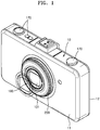
- FIG. 1 is a perspective view illustrating the front of an imaging apparatus according to an embodiment.
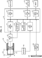
- FIG. 2 is a block diagram illustrating elements of the imaging apparatus, according to an embodiment.
- the imaging apparatus of the present embodiment may be any of various devices such as a digital still camera that captures a still image or a video camera that captures a motion picture.
- the imaging apparatus may include a main body 10, a zoom lens unit 100, an imaging unit 120, and a control unit 140.
- the main body 10 defines an outer appearance of the imaging apparatus.
- the zoom lens unit 100 is supported by the main body 10 such that an incident window 101 on which light is incident is exposed through a front surface 11 of the main body 10.
- a second barrel 114 (see FIG. 2 ) may move forward and backward along an optical axis 1 (see FIG. 2 ), as marked by a solid line and a dashed line of FIG. 1 , in order to adjust a zoom ratio of the zoom lens unit 100.
- the zoom lens unit 100 includes a plurality of lenses 115 for forming image light on an imaging surface of the imaging unit 120, and first and second barrels 113 and 114 that support the lenses 115.
- the lenses 115 may be arranged to change an interval therebetween. When an interval between the lenses 115 is changed, a zoom ratio or a focal point may be adjusted. Positions of the lenses 115 may be changed as the lenses 115 are driven by a driving unit including a zoom motor 160.
- the lenses 115 may include a zoom lens that increases or reduces a size of a subject and a focus lens that adjusts a focal point of the subject.
- the zoom lens unit 100 may have any structure which allows the zoom lens unit 100 to perform wide-angle shooting and telephoto shooting.
- the zoom lens unit 100 may include the first barrel 113 by which a first lens group 111 is supported and the second barrel 114 by which a second lens group 112 is supported.
- the second barrel 114 may be moved along the optical axis 1 by, for example, the zoom motor 160. Accordingly, wide-angle shooting and telephoto shooting may be performed.
- a lens control unit 142 of the control unit 140 controls positions of the lenses 115 to adjust a zoom ratio and a focal point.
- the zoom lens unit 100 may be fixed to the main body 10. When the zoom lens unit 100 is an interchangeable type of lens, the zoom lens unit 100 may be detachably attached to the main body 10.
- the zoom lens unit 100 is not limited to FIG. 2 , and may have any of various structures according to a zoom ratio or the like.
- control unit 140 may include an image converting unit 141, the lens control unit 142, a memory control unit 143, a display control unit 144, an image compression unit 149, a photographing control unit 145, and an input receiving unit 148.
- the imaging unit 120 includes an imaging device (not shown) that receives image light and converts the image light into an electrical signal.
- the imaging device includes a photoelectric conversion device such as a charge-coupled device (CCD) or a complementary metal oxide semiconductor (CMOS) chip, and converts image light that is incident thereon after passing through the lenses 115 into an electrical signal.
- the imaging unit 120 is driven by a control signal that is applied from the photographing control unit 145.
- the electrical signal that is generated by the imaging unit 120 is converted by the image converting unit 141 into image data.
- the photographing control unit 145 of the control unit 140 captures an image by controlling the imaging unit 120.
- the image converting unit 141 may convert the electrical signal of the imaging unit 120 into RGB data, and then may convert the RGB data into raw data such as a YUV signal including a luminance (Y) signal and a chrominance (UV) signal.
- a conversion process performed by the image converting unit 141 may include reducing driving noise of the imaging unit 120 that is included in the electrical signal by using, for example, a correlated-double sampling (CDS) circuit, adjusting a gain of a signal after the noise reduction by using an automatic gain control (AGC) circuit, converting an analog signal into a digital signal by using an analog-to-digital (A/D) converter, and performing signal processing such as defective pixel correction, gain control, white balance, or gamma correction on the digital signal.
- CDS correlated-double sampling
- AGC automatic gain control
- A/D analog-to-digital
- the memory control unit 143 controls the recording of data onto a memory 130 and the reading of recorded data or set information from the memory 130.
- the memory 130 may be a volatile internal memory, and may include a semiconductor memory device such as a synchronous dynamic random-access memory (SDRAM).
- SDRAM synchronous dynamic random-access memory
- the memory 130 may function as a buffer memory that temporarily stores the image data that is generated by the image converting unit 141 and as a working memory that is used to process data.
- the memory 130 may be a nonvolatile external memory, and may be a flash memory such as a memory stick or a secure digital/multimedia card SD/MMC, or a storage apparatus such as a hard disc drive (HDD), or an optical storage apparatus such as a digital versatile disc (DVD) or a compact disc (CD).
- HDD hard disc drive
- DVD digital versatile disc
- CD compact disc
- the image data that is compressed into a joint photographic experts group (JPEG) file, a tag image file (TIF), a graphics interchange format (GIF) file, or a personal computer exchange (PCX) file by the image compression unit 149 may be stored in the memory 130.
- JPEG joint photographic experts group
- TEF tag image file
- GIF graphics interchange format
- PCX personal computer exchange
- a display unit 150 may be disposed on, for example, a rear surface 12 of the main body 10, and may include a display device such as a liquid crystal display (LCD) device or an organic electroluminescent display device (e.g., an organic light-emitting diode (OLED)). Also, a touch panel that detects a touch and generates a signal corresponding to a position of the touch may be disposed on a surface of the display unit 150.
- a display device such as a liquid crystal display (LCD) device or an organic electroluminescent display device (e.g., an organic light-emitting diode (OLED)).
- LCD liquid crystal display
- OLED organic light-emitting diode
- a touch panel that detects a touch and generates a signal corresponding to a position of the touch may be disposed on a surface of the display unit 150.
- the user input unit 170 may include any of various buttons or a rotary knob as shown in FIG. 1 .
- a user may capture an image and may check a captured image by using the user input unit 170.
- the display unit 150 may display a captured image and an image that is stored in the memory 130. Also, the display unit 150 may provide an image that assists the user in checking the framing of the subject to be photographed and photographing conditions.
- the image may be formed by the imaging unit 120 and provided to the user through the zoom lens unit 100, before the subject is photographed, along with photographing assistant information such as an iris value, a shutter speed, or a position of a focal point.
- the control unit 140 is electrically connected to the imaging unit 120, the zoom lens unit 100, the display unit 150, the user input unit 170, and the memory 130, and transmits/receives a control signal to/from the above elements to control operations of the above elements or processes data.
- the control unit 140 may include a microchip, or a circuit board including a microchip, and elements that are included in the control unit 140 may include software or circuits embedded in the control unit 140.
- the user may select a zoom ratio of the zoom lens unit 100 during an imaging process.
- a zoom ratio may be selected by manipulating a zoom ring 200.
- the zoom ring 200 is rotatably provided on the front surface 11 of the main body 10.
- the rotation of the zoom ring 200 is detected by a rotation detection unit 300.
- the rotation detection unit 300 of FIGS. 1 and 2 amplifies the rotation angle of the zoom ring 200 by an amplification ratio greater than 1 and detects the amplified rotation angle.
- a rotation detection signal of the rotation detection unit 300 is transmitted to the control unit 140.
- the control unit 140 calculates a rotation amount and a rotation direction of the zoom ring 200 based on the rotation detection signal, and drives the zoom lens unit 100 based on the calculated rotation amount and the calculated rotation direction. For example, the control unit 140 calculates a zoom ratio from the rotation amount and the rotation direction of the zoom ring 200, and determines a driving amount of the lenses 115 which corresponds to the zoom ratio. Next, the lens control unit 142 controls the zoom motor 160 in order to adjust the zoom ratio of the zoom lens unit 100 such that the zoom ratio corresponds to a manipulation amount of the zoom ring 200.
- FIG. 3 is a perspective view and a partial cross-sectional view illustrating the zoom ring 200 according to an embodiment.
- the zoom ring 200 is rotatably provided on the front surface 11 of the main body 10.
- the zoom ring 200 may be shaped to surround the zoom lens unit 100, and a rotational axis of the zoom ring 200 may be the same as the optical axis 1 (see FIG. 2 ).
- the user may rotate the zoom ring 200 that is provided on the front surface 11 by using one hand while holding the imaging apparatus in the other hand.
- a holder 230 is provided on the front surface 11 of the main body 10.
- a rib 231 that has an annular shape and protrudes along the optical axis 1 is provided on the holder 230.
- the zoom ring 200 may be supported by the rib 231 by being installed along the optical axis 1 onto the holder 230.
- a first support unit 201 and a second support unit 202 that are respectively supported by an outer surface 231a and a top surface 231b of the rib 231 are provided on the zoom ring 200.
- a lens guide 240 that has a ring shape and includes a hollow portion 241 through which the zoom lens unit 100 passes is disposed inside the zoom ring 200 in a radial direction of the zoom ring 200 and is coupled to the holder 230 by being installed along the optical axis 1 onto the holder 230.
- the lens guide 240 supports the zoom ring 200 so that the zoom ring 200 does not separate from the holder 230 along the optical axis 1.
- a third support unit 203 that protrudes inward in the radial direction may be provided on the zoom ring 200, and an outer support unit 242 that protrudes outward in the radial direction from an outer circumferential surface of the lens guide 240 and is disposed outside the third support unit 203 along the optical axis 1 may be provided on the lens guide 240.
- the zoom ring 200 may be disposed between the lens guide 240 and the holder 230 such that the zoom ring 200 does not move along the optical axis 1 and in the radial direction, and may be rotated relative to the holder 230 and the lens guide 240.
- An O-ring 250 may be disposed between the holder 230 and the zoom ring 200.
- the O-ring 250 may be provided in a recess portion 232 that is recessed from the outer surface 231a and the top surface 231b of the rib 231.
- the O-ring 250 may be formed of a material having elasticity such as rubber.
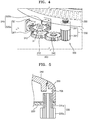
- FIG. 4 is a perspective view illustrating the rotation detection unit 300 that detects the rotation of the zoom ring 200, according to an embodiment.
- the rotation detection unit 300 includes a slit member 310 that is connected to the zoom ring 200 and rotates, and a sensor 320 that detects the rotation of the slit member 310.
- the slit member 310 includes a plurality of blades 311 that are arranged at predetermined intervals in a rotation direction.
- the zoom ring 200 may be connected to the slit member 310 through the rotation member 330, and thereby the slit member 310 rotates when the zoom ring 200 rotates.
- the rotation member 330 includes a first connection unit 331 that is connected to the zoom ring 200, and a second connection unit 332 that is connected to the slit member 310.
- a rotation connection unit 350 may be disposed between the second connection unit 332 and the slit member 310.
- FIG. 5 is a cross-sectional view illustrating a connection structure between the rotation member 330 and the zoom ring 200, according to an embodiment.
- the rotation member 330 and the zoom ring 200 are connected to each other by using friction contact.
- the first connection unit 331 contacts an inner circumferential surface 206 of the zoom ring 200 by friction contact.
- the first connection unit 331 may include, for example, a friction portion 331a that has a cylindrical shape.
- the friction portion 331a may be, for example, a rubber ring.
- the zoom ring 200 and the slit member 310 may be connected to each other without providing a power transfer unit on the zoom ring 200.
- a diameter of the friction portion 331a is less than a diameter of the inner circumferential surface 206 of the zoom ring 200. Accordingly, a rotation ratio of the slit member 310 to the zoom ring 200 may be greater than 1.
- FIG. 6 is a cross-sectional view illustrating a connection structure between the rotation member 330 and the zoom ring 200, according to another embodiment.
- the rotation member 330 may be connected to the zoom ring 200 via a gear connection structure.
- a ring gear 207 may be provided on the inner circumferential surface 206 of the zoom ring 200, and the first connection unit 331 may include a gear 331b that engages with the ring gear 207.
- the number of teeth of the gear 331b is less than the number of teeth of the ring gear 207. Accordingly, a rotation ratio of the slit member 310 to the zoom ring 200 may be greater than 1.
- a space for connecting the first connection unit 331 and the zoom ring 200 may be obtained by removing a part of the holder 230 and a part of the rib 231.
- the rotation connection unit 350 may include any of various rotation transmission structures that may transmit a rotational force of the rotation member 330 to the slit member 310, such as a gear connection structure or a belt connection structure.
- a gear connection structure may be employed as a connection structure between the rotation member 330 and the slit member 310.
- the second connection unit 332 may include a gear 332a as shown in FIG. 5 .
- a gear 312 that has a common axis with the plurality of blades 311 and is spaced apart in an axial direction from the blades 311 may be provided on the slit member 310 as shown in FIG. 4 .
- the gear 332a and the gear 312 may directly engage with each other, or at least one connection gear 340 may be disposed between the gear 332a and the gear 312 as shown in FIG. 4 .
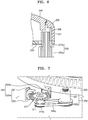
- FIG. 7 is a perspective view illustrating a connection structure between the rotation member 330 and the slit member 310, according to an embodiment.
- the second connection unit 332 may include a driving pulley 332b by which a belt (or a wire) 340a is supported, and a driven pulley 312a that forms a pair with the driving pulley 332b, instead of the gear 312 (see FIG. 4 ), may be provided on the slit member 310.
- the sensor 320 may include first and second sensors 320a and 320b.
- the first and second sensors 320a and 320b may be, for example, PI (photo-interrupter) sensors.
- Each of the first and second sensors 320a and 320b may include a light-emitting unit 321 and a light-receiving unit 322 that are disposed with the blades 311 therebetween.
- a rotation amount of the zoom ring 200 may be detected by counting the number of the blades 311 passing between the light-emitting unit 321 and the light-receiving unit 322 (that is, by counting the number of times light is detected in the light-receiving unit 322 according to positions of the blades 311).
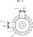
- FIG. 8 is a top plan view illustrating an arrangement of the first and second sensors 320a and 320b, according to an embodiment.
- the first and second sensors 320a and 320b are arranged such that detection signals S1 and S2 have a phase difference therebetween. That is, the first and second sensors 320a and 320b are arranged such that the detection signals S1 and S2 do not completely overlap with each other.
- the first and second sensors 320a and 320b are arranged such that the detection signals S1 and S2 have a phase difference of °90 in FIG. 8 , a phase difference is not limited thereto.
- a phase difference between the detection signals S1 and S2 may be determined such that a rising edge (or a falling edge) of the detection signal S1 is not the same as a rising edge (or a falling edge) of the detection signal S2.
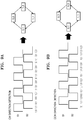
- FIG. 9A illustrates the detection signals S1 and S2 of the first and second sensors 320a and 320b when the zoom ring 200 rotates clockwise CW, according to an embodiment.
- FIG. 9B illustrates the detection signals S1 and S2 of the first and second sensors 320a and 320b when the zoom ring 200 rotates counterclockwise CCW.
- '1' denotes a state where the blades 311 are detected
- '0' denotes a state where the blades 311 are not detected.
- a combination of the detection signals S1 and S2 at an arbitrary time is one of four states (1, 0), (1, 1), (0, 1), and (0, 0). Referring to FIG.
- a combination of the detection signals S1 and S2 changes in a circular loop fashion, that is, (1, 0)->(1, 1)->(0, 1)->(0, 0).
- FIG. 9B when the zoom ring 200 rotates counterclockwise CCW, a combination of the detection signals S1 and S2 changes in a circular loop fashion, that is, (0, 0)->(0, 1)->(1, 1)->(1, 0).
- a rotation direction of the zoom ring 200 may be detected by determining, based on the detection signals S1 and S2, the circular loop fashion in which a combination of the detection signals S1 and S2 changes.
- a combination of the detection signals S1 and S2 may be as follows.
- a rotation amount of the zoom ring 200 may be calculated by counting the number of states 'H' or states 'L" of any one of the detection signals S1 and S2 of the first and second sensors 320a and 320b and multiplying the number by a rotation angle of the slit member 310 corresponding to a period of any one of the detection signals S1 and S2 and a rotation ratio of the slit member 310 to the zoom ring 200.
- a diameter of the friction portion 331a or the number of teeth of the gear 331b is much less than a diameter of the inner circumferential surface 206 of the zoom ring 200 or the number of teeth of the gear 207 that is provided on the inner circumferential surface 206.
- a rotation ratio of the slit member 310 to the zoom ring 200 may be greater than 1. Accordingly, a rotation amount (or a rotation angle) of the zoom ring 200 is amplified and transmitted to the slit member 310. That is to say, the mechanical transmission provided between the zoom ring 200 and slit member 310 is configured such that the slit member 310 is rotated through a greater angle than the zoom ring 200.
- a rotation ratio of the slit member 310 to the zoom ring 200 may be greater than 1, a rotation amount of the zoom ring 200 may be detected by the sensor 320 with a very high sensitivity, and a zoom ratio may be precisely adjusted by slightly rotating the zoom ring 200.
- the slit member 310 is rotated through a greater angle than the zoom ring 200, and the greater angle is more easily accurately detected than the angle through which the zoom ring 200 may be rotated.
- precise zoom ratio adjustment is enabled because it is controlled in dependence upon the amplified angle of rotation.
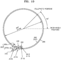
- FIG. 10 is a view illustrating a rotation ratio of the slit member 310 to the zoom ring 200, according to an embodiment.
- a diameter of the inner circumferential surface 206 of the zoom ring 200 is 57 mm
- a diameter of the first connection unit 331 that friction-contacts the inner circumferential surface 206 is 3 mm.
- the number of teeth of the gear 332a of the second connection unit 332 is 10
- the number of teeth of the gear 312 of the slit member 310 is 19. Since the connection gear 340 is a single stage gear, the number of teeth of the connection gear 340 does not affect a rotation ratio.
- the rotation ratio is 10.
- a rotation amount of the zoom ring 200 may be detected with a very high sensitivity.
- the slit member 310 may rotate by 450°, and a zoom ratio may be adjusted from a wide-angle position to a telephoto position by rotating the zoom ring by 45°.
- a zoom ratio between a wide-angle position and a telephoto position may be divided into 45 increments and may be adjusted by setting an interval between adjacent blades 311 to, for example, 10°.
- the rotation of the zoom ring 200 may be stably detected with no rotation detection error by selecting an interval between the blades 311 suitable for high speed rotation of the zoom ring 200.
- a rotation ratio may be determined based on a diameter of the friction portion 331a, numbers of teeth of the gear 332a and the gear 312, and diameters of the driving pulley 332b and the driven pulley 312a, and a desired sensitivity with which a rotation amount is detected may be obtained by adjusting the above parameters.
- FIG. 11 is a cross-sectional view for explaining a method of adjusting the rotation ratio of the slit member to the zoom ring, according to an embodiment.
- a rotation ratio may be adjusted by employing a double stage gear as an embodiment of the connection gear 340 as shown in FIG. 11 .
- a connection gear 340b includes a gear 341 that engages with the gear 332a, and a gear 342 that engages with the gear 312.
- the number of teeth of the gear 341 is less than the number of teeth of the gear 342.
- a rotation ratio may be further increased.
- a rotation ratio may be reduced by causing the number of teeth of the gear 341 to be greater than the number of teeth of the gear 342.
- the conventional method has a limitation in reducing an interval between black and white and thus has a limitation in increasing a sensitivity with which a rotation amount of the zoom ring 200 is detected. Also, since the rotation amount of the zoom ring 200 is directly detected without being amplified, when the zoom ring 200 rotates at a high speed, a detection error may occur.
- a rotation ratio of the slit member 310 to the zoom ring 200 is greater than 1, a rotation amount of the zoom ring 200 may be detected with a high sensitivity. Also, a zoom ratio between a wide-angle position and a telephoto position may be selected by reducing a rotation amount of the zoom ring 200, and even when the zoom ring 200 rotates at a high speed, the rotation of the zoom ring 200 may be stably detected.
- a rotation amount of the zoom ring 200 may be detected with a higher precision than when a reflective optical sensor is employed.
- the apparatus described herein may comprise a processor, a memory for storing program data to be executed by the processor, a permanent storage such as a disk drive, a communications port for handling communications with external devices, and user interface devices, including a display, touch panel, keys, buttons, etc.
- these software modules may be stored as program instructions or computer readable code executable by the processor on a computer-readable media such as non-transitory magnetic storage media (e.g., magnetic tapes, hard disks, floppy disks), non-transitory optical recording media (e.g., CD-ROMs, Digital Versatile Discs (DVDs), etc.), and non-transitory solid state memory (e.g., random-access memory (RAM), read-only memory (ROM), static random-access memory (SRAM), electrically erasable programmable read-only memory (EEPROM), flash memory, thumb drives, etc.).
- the computer readable recording media may also be distributed over network coupled computer systems so that the computer readable code is stored and executed in a distributed fashion. This computer readable recording media may be read by the computer, stored in the memory, and executed by the processor.
- the invention may be described in terms of functional block components and various processing steps. Such functional blocks may be realized by any number of hardware and/or software components configured to perform the specified functions.
- the invention may employ various integrated circuit components, e.g., memory elements, processing elements, logic elements, look-up tables, and the like, which may carry out a variety of functions under the control of one or more microprocessors or other control devices.
- the elements of the invention are implemented using software programming or software elements
- the invention may be implemented with any programming or scripting language such as C, C++, JAVA®, assembler, or the like, with the various algorithms being implemented with any combination of data structures, objects, processes, routines or other programming elements.
- Functional aspects may be implemented in algorithms that execute on one or more processors.
- the invention may employ any number of conventional techniques for electronics configuration, signal processing and/or control, data processing and the like.
Landscapes
- Physics & Mathematics (AREA)
- General Physics & Mathematics (AREA)
- Optics & Photonics (AREA)
- Engineering & Computer Science (AREA)
- Multimedia (AREA)
- Signal Processing (AREA)
- Lens Barrels (AREA)
- Studio Devices (AREA)
Claims (9)
- Bildgebende Vorrichtung, die Folgendes umfasst:einen Hauptkörper (10);eine Zoomlinseneinheit (100), die Bildlicht auf einer Bildgebungseinheit (120) bildet und vom Hauptkörper (10) gestützt wird;einen Zoomring (200), der um die Zoomlinseneinheit (100) am Hauptkörper (10) bereitgestellt ist und manuell gedreht werden muss;einen Halter (230), der auf einer vorderen Fläche (11) des Hauptkörpers (10) bereitgestellt ist;wobei der Halter (230) eine Rippe (231) umfasst, die den Zoomring (200) drehbar stützt;eine Linsenführung (240), die eine Ringform aufweist und einen hohlen Abschnitt (241) beinhaltet, durch den die Zoomlinseneinheit (100) geführt wird,wobei die Linsenführung (240) im Zoomring (200) radial angeordnet ist;wobei die Linsenführung (240) den Zoomring (200) derart stützt, dass sich der Zoomring entlang der optischen Achse nicht vom Halter (230) trennt, undwobei sich der Zoomring (200) weder entlang der optischen Achse (1) noch in die Radialrichtung bewegt und relativ zum Halter (230) und zur Linsenführung (240) gedreht werden kann,wobei die Vorrichtung ferner Folgendes umfasst:eine Drehungsdetektionseinheit (300), die einen Drehwinkel des Zoomrings (200) verstärkt, den verstärkten Drehwinkel detektiert und ein Detektionssignal ausgibt; undeine Steuereinheit (140), die durch Ansteuern der Zoomlinseneinheit (100) auf Basis des Detektionssignals der Drehungsdetektionseinheit (300) ein Zoomverhältnis steuert.
- Bildgebende Vorrichtung nach Anspruch 1, wobei die Drehungsdetektionseinheit (300) Folgendes umfasst:ein Schlitzelement (310), das mit dem Zoomring (200) verbunden ist und durch Drehen des Zoomrings (200) gedreht wird, wobei das Drehverhältnis des Schlitzelements (310) zum Zoomring größer ist als 1; undeinen Sensor (320), der eine Drehung des Schlitzelements (310) detektiert und das Detektionssignal ausgibt.
- Bildgebende Vorrichtung nach Anspruch 2, die ferner ein Drehelement (330) umfasst, das zwischen dem Schlitzelement (310) und dem Zoomring (200) angeordnet ist, und eine erste Verbindungseinheit (331), die mit dem Zoomring (200) verbunden ist, und eine zweite Verbindungseinheit (332), die mit dem Schlitzelement (310) verbunden ist, umfasst.
- Bildgebende Vorrichtung nach Anspruch 3, wobei die erste Verbindungseinheit (331) einen Reibungsabschnitt umfasst, der eine innere Umfangsfläche des Zoomrings (200) durch Reibkontakt kontaktiert und dreht,
wobei ein Durchmesser der inneren Umfangsfläche größer ist als ein Durchmesser des Reibungsabschnitts. - Bildgebende Vorrichtung nach Anspruch 3, die ferner ein Hohlrad (207) umfasst, das auf einer inneren Umfangsfläche des Zoomrings (200) angeordnet ist,
wobei die erste Verbindungseinheit (331) ein Zahnrad (331b) umfasst, das in das Hohlrad (207) eingreift, und wobei eine Anzahl von Zähnen des Zahnrads (331b) kleiner ist als eine Anzahl von Zähnen des Hohlrads (207) . - Bildgebende Vorrichtung nach Anspruch 3, die ferner eine Drehungsverbindungseinheit (331) umfasst, die eine Zahnradverbindungsstruktur umfasst, die die zweite Verbindungseinheit (332) und das Schlitzelement (310) verbindet.
- Bildgebende Vorrichtung nach einem der Ansprüche 2 bis 6, wobei der Sensor (320) einen ersten Sensor (320a) und einen zweiten Sensor (320b) umfasst,
wobei der erste und der zweite Sensor (320a, 320b) derart angeordnet sind, dass jeweilige Detektionssignale des ersten und des zweiten Sensors (320a, 320b) eine Phasendifferenz dazwischen aufweisen. - Bildgebende Vorrichtung nach einem der Ansprüche 2 bis 6, wobei der Sensor (320) einen Fotounterbrechersensor umfasst, der eine Lichtemissionseinheit (321) und eine Lichtempfangseinheit (322) umfasst, die derart angeordnet sind, dass sie, mit Blättern des Schlitzelements (310) dazwischen, einander zugewandt sind.
- Bildgebende Vorrichtung nach Anspruch 1, wobei eine Drehachse des Zoomrings (200) dieselbe ist wie eine optische Achse der Zoomlinseneinheit (110).
Applications Claiming Priority (1)
| Application Number | Priority Date | Filing Date | Title |
|---|---|---|---|
| KR1020130162658A KR102156292B1 (ko) | 2013-12-24 | 2013-12-24 | 촬상 장치 |
Publications (2)
| Publication Number | Publication Date |
|---|---|
| EP2889662A1 EP2889662A1 (de) | 2015-07-01 |
| EP2889662B1 true EP2889662B1 (de) | 2019-01-02 |
Family
ID=51999226
Family Applications (1)
| Application Number | Title | Priority Date | Filing Date |
|---|---|---|---|
| EP14193213.7A Not-in-force EP2889662B1 (de) | 2013-12-24 | 2014-11-14 | Abbildungsvorrichtung |
Country Status (4)
| Country | Link |
|---|---|
| US (1) | US9743006B2 (de) |
| EP (1) | EP2889662B1 (de) |
| KR (1) | KR102156292B1 (de) |
| CN (1) | CN104735346A (de) |
Families Citing this family (9)
| Publication number | Priority date | Publication date | Assignee | Title |
|---|---|---|---|---|
| CN106657727A (zh) * | 2016-11-02 | 2017-05-10 | 深圳市维海德技术股份有限公司 | 一种摄像机变焦距传感机构及云台摄像组件 |
| CN109597263B (zh) * | 2017-09-30 | 2024-03-08 | 杭州海康微影传感科技有限公司 | 一种成像设备和一种镜头调焦方法 |
| JP7034755B2 (ja) * | 2018-02-19 | 2022-03-14 | キヤノン株式会社 | 光学機器 |
| KR102297281B1 (ko) * | 2019-03-21 | 2021-09-02 | 삼성전기주식회사 | 조리개 모듈 및 이를 포함하는 카메라 모듈 |
| JP7289733B2 (ja) * | 2019-06-20 | 2023-06-12 | キヤノン株式会社 | 位置検出装置 |
| CN112261287B (zh) * | 2020-10-10 | 2023-03-21 | Oppo(重庆)智能科技有限公司 | 变焦控制方法、装置、电子设备和计算机可读存储介质 |
| WO2025074785A1 (ja) * | 2023-10-06 | 2025-04-10 | 株式会社ニコン | 交換レンズ及びカメラボディ |
| WO2025074788A1 (ja) * | 2023-10-06 | 2025-04-10 | 株式会社ニコン | 撮像装置及び交換レンズ |
| KR102696976B1 (ko) * | 2023-11-14 | 2024-08-20 | 주식회사 파이비스 | 이송되는 오브젝트의 표면을 검사하는 시스템에서 카메라를 정렬하기 위한 장치 및 방법 |
Citations (2)
| Publication number | Priority date | Publication date | Assignee | Title |
|---|---|---|---|---|
| JPH09230218A (ja) * | 1996-02-23 | 1997-09-05 | Minolta Co Ltd | カメラ |
| US20140184903A1 (en) * | 2012-12-27 | 2014-07-03 | Canon Kabushiki Kaisha | Image-pickup apparatus |
Family Cites Families (21)
| Publication number | Priority date | Publication date | Assignee | Title |
|---|---|---|---|---|
| US6963366B2 (en) * | 1996-06-19 | 2005-11-08 | Canon Kabushiki Kaisha | Image pickup apparatus |
| KR200248340Y1 (ko) * | 1998-10-28 | 2001-12-13 | 이중구 | 줌렌즈배럴구동시스템을가지는카메라 |
| JP2003177298A (ja) * | 2001-12-12 | 2003-06-27 | Canon Inc | 変位検出装置、該変位検出装置を用いたレンズ装置および撮像装置 |
| JP3977184B2 (ja) * | 2002-07-22 | 2007-09-19 | キヤノン株式会社 | 光学装置および撮像装置 |
| JP4235425B2 (ja) * | 2002-09-20 | 2009-03-11 | Hoya株式会社 | フォトインタラプタ位置調節機構 |
| KR100595879B1 (ko) | 2003-11-21 | 2006-06-30 | 주식회사 팬택 | 수동 줌 기능이 부가된 디지털 카메라를 가지는 통신 단말기 |
| JP4575114B2 (ja) * | 2003-12-24 | 2010-11-04 | オリンパス株式会社 | ズームレンズ鏡筒 |
| JP2005223766A (ja) | 2004-02-06 | 2005-08-18 | Canon Inc | 撮像装置及びその制御方法 |
| JP4798178B2 (ja) * | 2008-07-11 | 2011-10-19 | ソニー株式会社 | レンズ鏡筒及び撮像装置 |
| JP2010068134A (ja) * | 2008-09-09 | 2010-03-25 | Olympus Corp | 撮像装置及びその撮影制御方法 |
| CN201269942Y (zh) * | 2008-09-27 | 2009-07-08 | 华晶科技股份有限公司 | 具变焦功能的相机镜头环 |
| JP5493851B2 (ja) * | 2009-12-30 | 2014-05-14 | ソニー株式会社 | レンズ鏡筒及び撮像装置 |
| KR101579737B1 (ko) * | 2010-01-05 | 2015-12-23 | 삼성전자주식회사 | 자동초점 조절 장치 및 카메라 시스템 |
| KR101653273B1 (ko) * | 2010-09-13 | 2016-09-01 | 삼성전자주식회사 | 초점 조절 장치 |
| JP5574899B2 (ja) * | 2010-09-24 | 2014-08-20 | キヤノン株式会社 | ロータリーエンコーダ及びこれを備えた光学機器 |
| KR101817651B1 (ko) * | 2011-02-11 | 2018-02-21 | 삼성전자주식회사 | 줌 렌즈 경통 조립체 |
| CN103080804B (zh) | 2011-03-29 | 2016-03-02 | 松下电器产业株式会社 | 可更换镜头、相机机身及数码相机 |
| JP5161398B2 (ja) * | 2011-06-08 | 2013-03-13 | オリンパスイメージング株式会社 | カメラシステム及びレンズ鏡筒 |
| WO2013046896A1 (ja) * | 2011-09-30 | 2013-04-04 | 富士フイルム株式会社 | レンズ装置、撮像ユニット、及び撮像装置 |
| JP2013108971A (ja) * | 2011-10-25 | 2013-06-06 | Ricoh Co Ltd | 角度検出装置、モータ駆動装置及び画像形成装置 |
| CN104471459B (zh) * | 2012-08-29 | 2017-03-08 | 富士胶片株式会社 | 在透镜镜筒上装卸自如的驱动装置、进行其处理控制的方法及调整方法 |
-
2013
- 2013-12-24 KR KR1020130162658A patent/KR102156292B1/ko not_active Expired - Fee Related
-
2014
- 2014-09-30 US US14/501,690 patent/US9743006B2/en not_active Expired - Fee Related
- 2014-11-14 EP EP14193213.7A patent/EP2889662B1/de not_active Not-in-force
- 2014-12-24 CN CN201410817890.5A patent/CN104735346A/zh not_active Withdrawn
Patent Citations (2)
| Publication number | Priority date | Publication date | Assignee | Title |
|---|---|---|---|---|
| JPH09230218A (ja) * | 1996-02-23 | 1997-09-05 | Minolta Co Ltd | カメラ |
| US20140184903A1 (en) * | 2012-12-27 | 2014-07-03 | Canon Kabushiki Kaisha | Image-pickup apparatus |
Also Published As
| Publication number | Publication date |
|---|---|
| EP2889662A1 (de) | 2015-07-01 |
| US20150181129A1 (en) | 2015-06-25 |
| CN104735346A (zh) | 2015-06-24 |
| US9743006B2 (en) | 2017-08-22 |
| KR102156292B1 (ko) | 2020-09-15 |
| KR20150074660A (ko) | 2015-07-02 |
Similar Documents
| Publication | Publication Date | Title |
|---|---|---|
| EP2889662B1 (de) | Abbildungsvorrichtung | |
| US9635236B2 (en) | Camera body, camera system, and method of controlling camera-body blur correction | |
| US20140036134A1 (en) | Focus adjustment device and focus adjustment method | |
| US9918004B2 (en) | Camera body capable of driving an image sensor along an optical axis in response to a change in an optical state of an object image | |
| US11010030B2 (en) | Electronic apparatus capable of performing display control based on display mode, control method thereof, and non-transitory computer readable medium | |
| CN102402101A (zh) | 光量调节设备 | |
| US8547454B2 (en) | Digital image photographing apparatuses and methods of controlling the same to provide location information | |
| JP6652569B2 (ja) | レンズ鏡筒及び撮影装置 | |
| US9179094B2 (en) | Photographing apparatus and method of controlling the same | |
| US8947577B2 (en) | Lens barrel assembly and photographing apparatus having the same | |
| US11689805B2 (en) | Image capturing apparatus, method of controlling the same, and storage medium | |
| JP4924321B2 (ja) | 撮像装置、手振れ検出素子のキャリブレーション実行方法およびプログラム | |
| US9736352B2 (en) | Imaging apparatus and camera body | |
| JP6653790B2 (ja) | 撮像装置、撮像方法、及びプログラム | |
| US9654682B2 (en) | Imaging apparatus | |
| US9204057B2 (en) | Imaging apparatus for shading correction | |
| US8902124B2 (en) | Digital image signal processing apparatus for displaying different images respectively on display units and method of controlling the same | |
| US8224171B2 (en) | Method and apparatus for driving lens barrel, digital photographing apparatus, and computer-readable storage medium | |
| JP6799411B2 (ja) | 焦点検出装置及び方法、及び撮像装置 | |
| JP4313766B2 (ja) | 撮影装置 | |
| JP2005294988A (ja) | 撮像装置および電子機器 | |
| JP2011197093A (ja) | 光学機器および交換レンズ |
Legal Events
| Date | Code | Title | Description |
|---|---|---|---|
| PUAI | Public reference made under article 153(3) epc to a published international application that has entered the european phase |
Free format text: ORIGINAL CODE: 0009012 |
|
| 17P | Request for examination filed |
Effective date: 20141114 |
|
| AK | Designated contracting states |
Kind code of ref document: A1 Designated state(s): AL AT BE BG CH CY CZ DE DK EE ES FI FR GB GR HR HU IE IS IT LI LT LU LV MC MK MT NL NO PL PT RO RS SE SI SK SM TR |
|
| AX | Request for extension of the european patent |
Extension state: BA ME |
|
| R17P | Request for examination filed (corrected) |
Effective date: 20151221 |
|
| RBV | Designated contracting states (corrected) |
Designated state(s): AL AT BE BG CH CY CZ DE DK EE ES FI FR GB GR HR HU IE IS IT LI LT LU LV MC MK MT NL NO PL PT RO RS SE SI SK SM TR |
|
| REG | Reference to a national code |
Ref country code: DE Ref legal event code: R079 Ref document number: 602014039025 Country of ref document: DE Free format text: PREVIOUS MAIN CLASS: G02B0007080000 Ipc: G02B0015140000 |
|
| RIC1 | Information provided on ipc code assigned before grant |
Ipc: G02B 7/10 20060101ALI20171102BHEP Ipc: H04N 5/232 20060101ALI20171102BHEP Ipc: G02B 15/14 20060101AFI20171102BHEP |
|
| STAA | Information on the status of an ep patent application or granted ep patent |
Free format text: STATUS: EXAMINATION IS IN PROGRESS |
|
| 17Q | First examination report despatched |
Effective date: 20171214 |
|
| GRAP | Despatch of communication of intention to grant a patent |
Free format text: ORIGINAL CODE: EPIDOSNIGR1 |
|
| STAA | Information on the status of an ep patent application or granted ep patent |
Free format text: STATUS: GRANT OF PATENT IS INTENDED |
|
| INTG | Intention to grant announced |
Effective date: 20180816 |
|
| GRAS | Grant fee paid |
Free format text: ORIGINAL CODE: EPIDOSNIGR3 |
|
| GRAA | (expected) grant |
Free format text: ORIGINAL CODE: 0009210 |
|
| STAA | Information on the status of an ep patent application or granted ep patent |
Free format text: STATUS: THE PATENT HAS BEEN GRANTED |
|
| AK | Designated contracting states |
Kind code of ref document: B1 Designated state(s): AL AT BE BG CH CY CZ DE DK EE ES FI FR GB GR HR HU IE IS IT LI LT LU LV MC MK MT NL NO PL PT RO RS SE SI SK SM TR |
|
| REG | Reference to a national code |
Ref country code: GB Ref legal event code: FG4D |
|
| REG | Reference to a national code |
Ref country code: CH Ref legal event code: EP Ref country code: AT Ref legal event code: REF Ref document number: 1085125 Country of ref document: AT Kind code of ref document: T Effective date: 20190115 |
|
| REG | Reference to a national code |
Ref country code: IE Ref legal event code: FG4D |
|
| REG | Reference to a national code |
Ref country code: DE Ref legal event code: R096 Ref document number: 602014039025 Country of ref document: DE |
|
| REG | Reference to a national code |
Ref country code: NL Ref legal event code: FP |
|
| REG | Reference to a national code |
Ref country code: LT Ref legal event code: MG4D |
|
| REG | Reference to a national code |
Ref country code: AT Ref legal event code: MK05 Ref document number: 1085125 Country of ref document: AT Kind code of ref document: T Effective date: 20190102 |
|
| PG25 | Lapsed in a contracting state [announced via postgrant information from national office to epo] |
Ref country code: PT Free format text: LAPSE BECAUSE OF FAILURE TO SUBMIT A TRANSLATION OF THE DESCRIPTION OR TO PAY THE FEE WITHIN THE PRESCRIBED TIME-LIMIT Effective date: 20190502 Ref country code: ES Free format text: LAPSE BECAUSE OF FAILURE TO SUBMIT A TRANSLATION OF THE DESCRIPTION OR TO PAY THE FEE WITHIN THE PRESCRIBED TIME-LIMIT Effective date: 20190102 Ref country code: NO Free format text: LAPSE BECAUSE OF FAILURE TO SUBMIT A TRANSLATION OF THE DESCRIPTION OR TO PAY THE FEE WITHIN THE PRESCRIBED TIME-LIMIT Effective date: 20190402 Ref country code: LT Free format text: LAPSE BECAUSE OF FAILURE TO SUBMIT A TRANSLATION OF THE DESCRIPTION OR TO PAY THE FEE WITHIN THE PRESCRIBED TIME-LIMIT Effective date: 20190102 Ref country code: FI Free format text: LAPSE BECAUSE OF FAILURE TO SUBMIT A TRANSLATION OF THE DESCRIPTION OR TO PAY THE FEE WITHIN THE PRESCRIBED TIME-LIMIT Effective date: 20190102 Ref country code: SE Free format text: LAPSE BECAUSE OF FAILURE TO SUBMIT A TRANSLATION OF THE DESCRIPTION OR TO PAY THE FEE WITHIN THE PRESCRIBED TIME-LIMIT Effective date: 20190102 Ref country code: PL Free format text: LAPSE BECAUSE OF FAILURE TO SUBMIT A TRANSLATION OF THE DESCRIPTION OR TO PAY THE FEE WITHIN THE PRESCRIBED TIME-LIMIT Effective date: 20190102 |
|
| PG25 | Lapsed in a contracting state [announced via postgrant information from national office to epo] |
Ref country code: GR Free format text: LAPSE BECAUSE OF FAILURE TO SUBMIT A TRANSLATION OF THE DESCRIPTION OR TO PAY THE FEE WITHIN THE PRESCRIBED TIME-LIMIT Effective date: 20190403 Ref country code: BG Free format text: LAPSE BECAUSE OF FAILURE TO SUBMIT A TRANSLATION OF THE DESCRIPTION OR TO PAY THE FEE WITHIN THE PRESCRIBED TIME-LIMIT Effective date: 20190402 Ref country code: RS Free format text: LAPSE BECAUSE OF FAILURE TO SUBMIT A TRANSLATION OF THE DESCRIPTION OR TO PAY THE FEE WITHIN THE PRESCRIBED TIME-LIMIT Effective date: 20190102 Ref country code: HR Free format text: LAPSE BECAUSE OF FAILURE TO SUBMIT A TRANSLATION OF THE DESCRIPTION OR TO PAY THE FEE WITHIN THE PRESCRIBED TIME-LIMIT Effective date: 20190102 Ref country code: IS Free format text: LAPSE BECAUSE OF FAILURE TO SUBMIT A TRANSLATION OF THE DESCRIPTION OR TO PAY THE FEE WITHIN THE PRESCRIBED TIME-LIMIT Effective date: 20190502 Ref country code: LV Free format text: LAPSE BECAUSE OF FAILURE TO SUBMIT A TRANSLATION OF THE DESCRIPTION OR TO PAY THE FEE WITHIN THE PRESCRIBED TIME-LIMIT Effective date: 20190102 |
|
| REG | Reference to a national code |
Ref country code: DE Ref legal event code: R097 Ref document number: 602014039025 Country of ref document: DE |
|
| PG25 | Lapsed in a contracting state [announced via postgrant information from national office to epo] |
Ref country code: IT Free format text: LAPSE BECAUSE OF FAILURE TO SUBMIT A TRANSLATION OF THE DESCRIPTION OR TO PAY THE FEE WITHIN THE PRESCRIBED TIME-LIMIT Effective date: 20190102 Ref country code: RO Free format text: LAPSE BECAUSE OF FAILURE TO SUBMIT A TRANSLATION OF THE DESCRIPTION OR TO PAY THE FEE WITHIN THE PRESCRIBED TIME-LIMIT Effective date: 20190102 Ref country code: CZ Free format text: LAPSE BECAUSE OF FAILURE TO SUBMIT A TRANSLATION OF THE DESCRIPTION OR TO PAY THE FEE WITHIN THE PRESCRIBED TIME-LIMIT Effective date: 20190102 Ref country code: SK Free format text: LAPSE BECAUSE OF FAILURE TO SUBMIT A TRANSLATION OF THE DESCRIPTION OR TO PAY THE FEE WITHIN THE PRESCRIBED TIME-LIMIT Effective date: 20190102 Ref country code: AT Free format text: LAPSE BECAUSE OF FAILURE TO SUBMIT A TRANSLATION OF THE DESCRIPTION OR TO PAY THE FEE WITHIN THE PRESCRIBED TIME-LIMIT Effective date: 20190102 Ref country code: AL Free format text: LAPSE BECAUSE OF FAILURE TO SUBMIT A TRANSLATION OF THE DESCRIPTION OR TO PAY THE FEE WITHIN THE PRESCRIBED TIME-LIMIT Effective date: 20190102 Ref country code: EE Free format text: LAPSE BECAUSE OF FAILURE TO SUBMIT A TRANSLATION OF THE DESCRIPTION OR TO PAY THE FEE WITHIN THE PRESCRIBED TIME-LIMIT Effective date: 20190102 Ref country code: DK Free format text: LAPSE BECAUSE OF FAILURE TO SUBMIT A TRANSLATION OF THE DESCRIPTION OR TO PAY THE FEE WITHIN THE PRESCRIBED TIME-LIMIT Effective date: 20190102 |
|
| PLBE | No opposition filed within time limit |
Free format text: ORIGINAL CODE: 0009261 |
|
| STAA | Information on the status of an ep patent application or granted ep patent |
Free format text: STATUS: NO OPPOSITION FILED WITHIN TIME LIMIT |
|
| PG25 | Lapsed in a contracting state [announced via postgrant information from national office to epo] |
Ref country code: SM Free format text: LAPSE BECAUSE OF FAILURE TO SUBMIT A TRANSLATION OF THE DESCRIPTION OR TO PAY THE FEE WITHIN THE PRESCRIBED TIME-LIMIT Effective date: 20190102 |
|
| 26N | No opposition filed |
Effective date: 20191003 |
|
| PG25 | Lapsed in a contracting state [announced via postgrant information from national office to epo] |
Ref country code: SI Free format text: LAPSE BECAUSE OF FAILURE TO SUBMIT A TRANSLATION OF THE DESCRIPTION OR TO PAY THE FEE WITHIN THE PRESCRIBED TIME-LIMIT Effective date: 20190102 |
|
| PG25 | Lapsed in a contracting state [announced via postgrant information from national office to epo] |
Ref country code: TR Free format text: LAPSE BECAUSE OF FAILURE TO SUBMIT A TRANSLATION OF THE DESCRIPTION OR TO PAY THE FEE WITHIN THE PRESCRIBED TIME-LIMIT Effective date: 20190102 |
|
| REG | Reference to a national code |
Ref country code: DE Ref legal event code: R119 Ref document number: 602014039025 Country of ref document: DE |
|
| REG | Reference to a national code |
Ref country code: CH Ref legal event code: PL |
|
| REG | Reference to a national code |
Ref country code: NL Ref legal event code: MM Effective date: 20191201 |
|
| PG25 | Lapsed in a contracting state [announced via postgrant information from national office to epo] |
Ref country code: CH Free format text: LAPSE BECAUSE OF NON-PAYMENT OF DUE FEES Effective date: 20191130 Ref country code: MC Free format text: LAPSE BECAUSE OF FAILURE TO SUBMIT A TRANSLATION OF THE DESCRIPTION OR TO PAY THE FEE WITHIN THE PRESCRIBED TIME-LIMIT Effective date: 20190102 Ref country code: LI Free format text: LAPSE BECAUSE OF NON-PAYMENT OF DUE FEES Effective date: 20191130 Ref country code: LU Free format text: LAPSE BECAUSE OF NON-PAYMENT OF DUE FEES Effective date: 20191114 |
|
| REG | Reference to a national code |
Ref country code: BE Ref legal event code: MM Effective date: 20191130 |
|
| GBPC | Gb: european patent ceased through non-payment of renewal fee |
Effective date: 20191114 |
|
| PG25 | Lapsed in a contracting state [announced via postgrant information from national office to epo] |
Ref country code: NL Free format text: LAPSE BECAUSE OF NON-PAYMENT OF DUE FEES Effective date: 20191201 |
|
| PG25 | Lapsed in a contracting state [announced via postgrant information from national office to epo] |
Ref country code: DE Free format text: LAPSE BECAUSE OF NON-PAYMENT OF DUE FEES Effective date: 20200603 Ref country code: IE Free format text: LAPSE BECAUSE OF NON-PAYMENT OF DUE FEES Effective date: 20191114 Ref country code: FR Free format text: LAPSE BECAUSE OF NON-PAYMENT OF DUE FEES Effective date: 20191130 Ref country code: GB Free format text: LAPSE BECAUSE OF NON-PAYMENT OF DUE FEES Effective date: 20191114 |
|
| PG25 | Lapsed in a contracting state [announced via postgrant information from national office to epo] |
Ref country code: BE Free format text: LAPSE BECAUSE OF NON-PAYMENT OF DUE FEES Effective date: 20191130 |
|
| PG25 | Lapsed in a contracting state [announced via postgrant information from national office to epo] |
Ref country code: CY Free format text: LAPSE BECAUSE OF FAILURE TO SUBMIT A TRANSLATION OF THE DESCRIPTION OR TO PAY THE FEE WITHIN THE PRESCRIBED TIME-LIMIT Effective date: 20190102 |
|
| PG25 | Lapsed in a contracting state [announced via postgrant information from national office to epo] |
Ref country code: MT Free format text: LAPSE BECAUSE OF FAILURE TO SUBMIT A TRANSLATION OF THE DESCRIPTION OR TO PAY THE FEE WITHIN THE PRESCRIBED TIME-LIMIT Effective date: 20190102 Ref country code: HU Free format text: LAPSE BECAUSE OF FAILURE TO SUBMIT A TRANSLATION OF THE DESCRIPTION OR TO PAY THE FEE WITHIN THE PRESCRIBED TIME-LIMIT; INVALID AB INITIO Effective date: 20141114 |
|
| PG25 | Lapsed in a contracting state [announced via postgrant information from national office to epo] |
Ref country code: MK Free format text: LAPSE BECAUSE OF FAILURE TO SUBMIT A TRANSLATION OF THE DESCRIPTION OR TO PAY THE FEE WITHIN THE PRESCRIBED TIME-LIMIT Effective date: 20190102 |