EP2889548A1 - Hydraulikblöcke mit Standardanschluss für Kombigeräte - Google Patents
Hydraulikblöcke mit Standardanschluss für Kombigeräte Download PDFInfo
- Publication number
- EP2889548A1 EP2889548A1 EP14197152.3A EP14197152A EP2889548A1 EP 2889548 A1 EP2889548 A1 EP 2889548A1 EP 14197152 A EP14197152 A EP 14197152A EP 2889548 A1 EP2889548 A1 EP 2889548A1
- Authority
- EP
- European Patent Office
- Prior art keywords
- hydraulic
- plate heat
- heat exchanger
- central heating
- blocks
- Prior art date
- Legal status (The legal status is an assumption and is not a legal conclusion. Google has not performed a legal analysis and makes no representation as to the accuracy of the status listed.)
- Granted
Links
- 238000010438 heat treatment Methods 0.000 claims description 35
- XLYOFNOQVPJJNP-UHFFFAOYSA-N water Substances O XLYOFNOQVPJJNP-UHFFFAOYSA-N 0.000 claims description 29
- 230000000712 assembly Effects 0.000 abstract description 3
- 238000000429 assembly Methods 0.000 abstract description 3
- 238000000034 method Methods 0.000 description 5
- 230000008569 process Effects 0.000 description 5
- 230000008859 change Effects 0.000 description 4
- 230000008901 benefit Effects 0.000 description 3
- 239000007788 liquid Substances 0.000 description 3
- 238000004519 manufacturing process Methods 0.000 description 3
- 230000006978 adaptation Effects 0.000 description 2
- 239000012530 fluid Substances 0.000 description 2
- 230000004913 activation Effects 0.000 description 1
- 239000008236 heating water Substances 0.000 description 1
- 230000006872 improvement Effects 0.000 description 1
- 239000000463 material Substances 0.000 description 1
- 239000002184 metal Substances 0.000 description 1
Images


Classifications
-
- F—MECHANICAL ENGINEERING; LIGHTING; HEATING; WEAPONS; BLASTING
- F24—HEATING; RANGES; VENTILATING
- F24H—FLUID HEATERS, e.g. WATER OR AIR HEATERS, HAVING HEAT-GENERATING MEANS, e.g. HEAT PUMPS, IN GENERAL
- F24H9/00—Details
- F24H9/14—Arrangements for connecting different sections, e.g. in water heaters
- F24H9/142—Connecting hydraulic components
Definitions
- the invention relates to hydraulic assemblies consisting of standard-port hydraulic blocks which fit the different-sized models of the plate heat exchangers which are one of the components of the combination devices.
- combi devices work on the principle of heat energy production by the heat transfer between the fluids in the system.
- the components that provide heat transfer on the combi unit are the hydraulic groups, where the liquids circulate in heat cells, and the plate heat exchangers connected to them.
- the plate heat exchangers are defined as heat exchangers consisting of metal plates with different bends and providing heat transfer between at least two liquids.
- plate heat exchangers are used in different dimensions for different combination systems with different heating capacities.
- the plate heat exchangers are integrated into the system by connecting them to the fluid channels on the hydraulic groups. Therefore, it is preferred that such hydraulic groups are designed, which consist of different hydraulic blocks that fit the designed depending on the combination system in different dimensions plate heat exchangers.
- hydraulic connections in hydraulic groups have significant differences, even with a family of devices in terms of various variables such as country specifications or different types of applications such as combination device, system, solar system, heating system.
- European patent no. EP1408292 relates to a heater for the central heating, comprising a hydraulic block, consisting of a first and a second module, for transferring the heating water to the heat exchanger.
- this hydraulic block of the heater also offers no connection advantages, which differ from the connections to the existing systems. These hydraulic blocks are also unable to provide standardization for connecting the plate heat exchangers in different dimensions.
- connection options of the hydraulic groups to the existing systems are very limited prevents standardization of the systems.
- the hydraulic groups which must be designed individually for each system, lead both to higher production costs, for example due to use of new parts, etc., as well as to complicated assembly steps because of their changed structure and instructions for the fitters. Taking these issues into consideration, technical improvement is necessary.
- the invention relates to standard port hydraulic blocks which are adapted to the different sized models of the plate heat exchangers which are one of the components of the combination devices and are designed to bring new benefits to the technical field.
- the main object of the invention is to represent a hydraulic group consisting of hydraulic blocks with standard connection, which allow the mounting of plate heat exchangers of different dimensions on the combination devices.
- Another object of the invention is to allow mounting of the plate heat exchangers in different dimensions only by the change in position of the hydraulic blocks.
- the invention relates to a hydraulic group for the combination devices for the realization of all of the above-mentioned and listed below in more detail goals.
- This hydraulic group is characterized in that it comprises at least a first hydraulic block and at least one second hydraulic block of exactly the same design and each of them is connected together with the other to the same plate heat exchanger.
- each of these hydraulic blocks has at least a first surface, at least a second surface, at least a third surface, and at least a fourth surface, and these surfaces can be positioned in different combinations connecting to plate heat exchangers of different dimensions and models enable.
- the invention comprises in a further preferred embodiment, the following inputs and outputs and channels that allow connection between the first, second, third and fourth surfaces of these hydraulic blocks and have different sizes and functions depending on the design: central heating input, central heating output, three-way valve connections, connection channels for the central heating circuit, service water inlet, Outgoing water outlet, service water connection channels, plate heat exchanger central heating input, plate heat exchanger central heating output, plate heat exchanger service water inlet and plate heat exchanger service water outlet.
- FIGS 5, 6 and 7 show the perspective views of the hydraulic blocks with plate heat exchangers of different dimensions.
- hydraulic group (10) which is the subject of the invention, is explained in more detail for the sake of better understanding and by way of non-limiting examples.
- the following explanations and figures therefore relate to the development of hydraulic units (10) of combination appliances, which are used especially in living areas (home, flat, workplace, etc.).
- FIG. 1 the perspective views of the hydraulic blocks are shown, which form a hydraulic group (10).
- This hydraulic group (10) comprises a first hydraulic block (11) and a second hydraulic block (12) of exactly the same design.
- the axis on which these first and second hydraulic blocks (11, 12) are positioned is referred to as horizontal axis (X) and the axis crossing the horizontal axis (X) at right angles (90 °) is defined as the vertical axis (Y).
- the upper cutting plane is defined as the first cutting plane (K1) and the lower cutting plane is defined as the second cutting plane (K2).
- Parallel to these, at least one horizontal axis of rotation (X1) is defined.
- a direction of rotation (R) is defined clockwise about the vertical axis (Y).
- the hydraulic blocks (11, 12) are arranged in a rectangular prism shape so as to be cut off at a corner along the vertical axis (Y).
- the second hydraulic block (12) is formed by the first hydraulic block (11) parallel to the vertical axis (Y) in the in illustration 1 Turning direction (R) is rotated 90 ° clockwise.
- the front surface of the first hydraulic block (11) becomes the first surface (F1)
- the front surface of the second hydraulic block (12) becomes the second surface (F2)
- the upper surfaces of the hydraulic blocks (11, 12) become third surfaces (F3 ) Are defined.
- On the third surfaces (F3) of the hydraulic blocks (11, 12) is in each case a circular flow channel in the vicinity of the cut corners.
- the channel on the first hydraulic block (11) is defined as the central heating input (H1) and the channel on the second hydraulic block (12) as the central heating output (H2).
- connection channels (H5, H6, H7, H8) for the central heating circuit are located in the central heating line and are used as pressure gauges, temperature sensors, pressure sensors, central heating filling valves, bypass lines, Pressure relief valves, expansion vessel pipe connections and others used.
- FIG 3 the sectional views of the hydraulic blocks (11, 12) at the height of the second sectional plane (K2) are shown.
- the channel shown in this sectional view on the second hydraulic block (12) near the cut-off corner on the vertical axis (Y) is cut off as the service water inlet (H9) and the channel shown on the first hydraulic block (11) in the vicinity of the The corner on the vertical axis (Y) is defined as the service water outlet (H10).
- the further channels shown in these sectional views are defined as connection channels (H11, H12, H13, H14) for the process water.
- These service water connection channels (H11, H12, H13, H14) are located in the service water line and are used as pressure sensors, temperature sensors, service water connection of central heating fill valves, pressure relief valves, filters, etc.
- FIG 4 become the perspective views in illustration 1 shown in two dimensions.
- the first and second surfaces (F1, F2) of the hydraulic blocks (11, 12) are shown from the front.
- the upper circular channel on the first surface (F1) of the first hydraulic block (11) near the right edge is defined as the central heating inlet (P1) of the plate heat exchanger.
- the lower circular channel in a variable diameter depending on the design is defined as the process water outlet (P4) of the plate heat exchanger.
- the upper circular channel on the second surface (F2) of the second hydraulic block (12) near the left edge is defined as the central heating output (P2) of the plate heat exchanger.
- the lower circular channel in a variable diameter depending on the design is defined as the service water inlet (P3) of the plate heat exchanger.
- FIGs 5 and 7 at least one plate heat exchanger (20) is shown, which is connected to the hydraulic blocks (11, 12).
- plate heat exchangers (20) are shown in different dimensions, which are adapted in the same hydraulic blocks (11, 12).
- the hydraulic blocks (11, 12) the Plate heat exchangers (20) in different dimensions adapted by being rotated about a rotation axis (support axis) parallel to the vertical axis (Y).
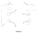
- FIG 8 the hydraulic blocks (11, 12) are shown in an alternative structure.
- the perspective views of the hydraulic blocks (11, 12) are shown, to which, according to this structure, a plate heat exchanger (20) is adapted, whose terminals have a cross-connection.
- These positions of the hydraulic blocks (11, 12) are made by rotating the second hydraulic block (12) 180 ° about the horizontal rotation axis (X1) and 90 ° in the rotation direction (R) parallel to the vertical axis (Y). In this position, the upper surface on the second hydraulic block (12) is defined as the fourth surface (F4).
- the upper channel, the service water inlet (P3) of the plate heat exchanger is located on the second surface (F2) at the front near the left edge and below the central heating outlet (P2) of the plate heat exchanger.
- a plate heat exchanger (20) is shown, whose corners - in the first position of the first hydraulic block (11) and the second hydraulic block (12) - each at the central heating inlet (P1) of the plate heat exchanger, central heating output (P2) of the plate heat exchanger, operating water inlet (P3) of Plate heat exchanger and water outlet (P4) of the plate heat exchanger are connected. Thereafter, the heat transfer takes place through the activation of the liquid inlets and outlets and the combi boiler heats the process water.
- connection ducts (H5, H6, H7, H8) for the central heating circuit or the connection ducts (H11, H12, H13, H14) for the service water can be fitted with the hydraulic blocks (11, 12) with a cover / a closure, inter alia, be sealed from different materials produced for this purpose.
- FIG 6 another position is shown in which the first hydraulic block (11) in the in illustration 1 the direction of rotation (R) is rotated by 90 °. It can be seen that a plate heat exchanger (20) with a different dimension - in this other position of the hydraulic blocks (11, 12) - is connected to the hydraulic blocks (11, 12).
- Figure 7 another position is shown in which the second hydraulic block (12) against the in illustration 1 the specified direction of rotation (R) is rotated by 90 °, while the first hydraulic block (11) in the in Figure 6 is shown position.
- a plate heat exchanger (20) with a different dimension can be adapted in the same way to the hydraulic blocks (11, 12), even if the hydraulic blocks (11, 12) are in a different position.
- the invention allows only by the change in position of the hydraulic blocks (11, 12) mounting the plate heat exchanger (20) in different dimensions on the hydraulic group (10) by the central heating input / output (P1, P2) of the plate heat exchanger and operating water inlet / outlet (P3 , P4) of the plate heat exchanger are mounted on the first surface (F1) and on the second surface (F2) of the hydraulic blocks (11, 12).
- plate heat exchanger (20) with different connections (cross-connection u.a.) Only by the position change to the hydraulic blocks (11, 12) can be connected.
- the position combinations of at least two hydraulic blocks (11, 12) obtained with only one design also minimize various problems, such as different connecting parts on the hydraulic blocks (11, 12) for adaptation to different systems or complicated / too many parts.
- the connection of plate heat exchangers (20) in at least three different dimensions (small, medium and large) and with at least two different types of connections (parallel and transverse) to the hydraulic group (10) allows.
Landscapes
- Engineering & Computer Science (AREA)
- Physics & Mathematics (AREA)
- Thermal Sciences (AREA)
- Chemical & Material Sciences (AREA)
- Combustion & Propulsion (AREA)
- Mechanical Engineering (AREA)
- General Engineering & Computer Science (AREA)
- Steam Or Hot-Water Central Heating Systems (AREA)
- Heat-Exchange Devices With Radiators And Conduit Assemblies (AREA)
Abstract
Description
- Die Erfindung betrifft Hydraulikgruppen, die aus Hydraulikblöcken mit Standardanschluss bestehen, die den in unterschiedlichen Abmessungen ausgelegten Modellen der Plattenwärmetauscher, die eine der Komponenten der Kombigeräte sind, passen.
- Wie bekannt ist, funktionieren Kombigeräte nach dem Prinzip der Wärmeenergieerzeugung durch die Wärmeübertragung zwischen den Flüssigkeiten im System. Die Komponenten, die am Kombigerät für Wärmeübertragung sorgen, sind die Hydraulikgruppen, bei denen die Flüssigkeiten in Wärmezellen zirkulieren, und die an diese angeschlossenen Plattenwärmetauscher.
- Die Plattenwärmetauscher werden als Wärmetauscher definiert, die aus Metallplatten mit verschiedenen Biegungen bestehen und für Wärmeübertragung zwischen mindestens zwei Flüssigkeiten sorgen. Im Stand der Technik werden Plattenwärmetauscher in unterschiedlichen Abmessungen für verschiedene Kombisysteme mit unterschiedlichen Heizleistungen verwendet. Die Plattenwärmetauscher werden dadurch in das System integriert, dass sie an die Flüssigkeitskanäle an den Hydraulikgruppen angeschlossen werden. Daher wird bevorzugt, dass solche Hydraulikgruppen konzipiert werden, die aus verschiedenen Hydraulikblöcken bestehen, die den je nach Kombisystem in unterschiedlichen Abmessungen ausgelegten Plattenwärmetauschern passen.
- Der Grund für die Auslegung verschiedener Hydraulikgruppen für unterschiedliche Kombisysteme ist, dass die Anschlüsse der hydraulischen Komponenten nicht austauschbar sind. Die Hydraulikgruppen sind je nach Heizleistung verschiedener Kombigeräte unterschiedlich und benötigen spezielle Anschlüsse. Unter Berücksichtigung der Einschränkungen der Anschlüsse von Plattenwärmetauschern ist es keinesfalls möglich, unterschiedlich große Plattenwärmetauscher mit einer einzigen Hydraulikgruppenauslegung für verschiedene Heizfunktionen eines Kombigerätes zu verwenden.
- Daneben weisen hydraulische Anschlüsse bei Hydraulikgruppen deutliche Unterschiede auf, sogar bei einer Gerätefamilie hinsichtlich verschiedener Variablen wie beispielsweise Landesspezifikationen oder unterschiedlicher Anwendungsarten wie beispielsweise Kombigerät, System, Solaranlage, Heizanlage.
- Das europäische Patent Nr.
EP1408292 betrifft ein Heizgerät für die Zentralheizung, das einen Hydraulikblock, bestehend aus einem ersten und einem zweiten Modul, zum Transfer des Heizwassers zum Wärmetauscher umfasst. Jedoch bietet auch dieser Hydraulikblock des Heizgerätes keine Anschlussvorteile, die sich von den Anschlüssen an den bestehenden Systemen unterscheiden. Auch diese Hydraulikblöcke sind nicht in der Lage, eine Standardisierung zum Anschluss der Plattenwärmetauscher in unterschiedlichen Abmessungen zu bieten. - Die Tatsache, dass die Anschlussmöglichkeiten der Hydraulikgruppen an den bestehenden Systemen sehr begrenzt sind, verhindert eine Standardisierung der Systeme. Aus diesem Grund führen die Hydraulikgruppen, die für jedes System individuell konzipiert werden müssen, sowohl zu höheren Herstellungskosten beispielsweise wegen Verwendung neuer Teile etc. als auch zu komplizierten Montageschritten wegen ihres geänderten Aufbaus sowie Einweisungen für die Monteure. Unter Berücksichtigung dieser Probleme ist eine technische Verbesserung notwendig.
- Die Erfindung betrifft Hydraulikblöcke mit Standardanschluss, die den in unterschiedlichen Abmessungen ausgelegten Modellen der Plattenwärmetauscher, die eine der Komponenten der Kombigeräte sind, passen und dazu entwickelt sind, dem technischen Bereich neue Vorteile zu bringen.
- Das Hauptziel der Erfindung ist, eine Hydraulikgruppe darzustellen, die aus Hydraulikblöcken mit Standardanschluss besteht, die die Montage von Plattenwärmetauschern in unterschiedlichen Abmessungen an den Kombigeräten ermöglichen.
- Ein weiteres Ziel der Erfindung ist, nur durch die Positionsänderung der Hydraulikblöcke eine Montage der Plattenwärmetauscher in unterschiedlichen Abmessungen zu ermöglichen.
- Die Erfindung betrifft eine Hydraulikgruppe für die Kombigeräte zur Verwirklichung aller oben erwähnten und nachfolgend detaillierter aufgeführten Ziele. Diese Hydraulikgruppe ist dadurch gekennzeichnet, dass sie mindestens einen ersten Hydraulikblock und mindestens einen zweiten Hydraulikblock exakt gleicher Bauform umfasst und jeder von diesen zusammen mit dem anderen an den gleichen Plattenwärmetauscher angeschlossen ist.
- Bei einer bevorzugten Ausführung der Erfindung weist jeder dieser Hydraulikblöcke mindestens eine erste Oberfläche, mindestens eine zweite Oberfläche, mindestens eine dritte Oberfläche und mindestens eine vierte Oberfläche auf und diese Oberflächen können in unterschiedlichen Kombinationen positioniert werden, die einen Anschluss an Plattenwärmetauscher in unterschiedlichen Abmessungen und Modellen ermöglichen.
- Die Erfindung umfasst bei einer weiteren bevorzugten Ausführung folgende Ein- und Ausgänge sowie Kanäle, die einen Anschluss zwischen den ersten, zweiten, dritten und vierten Oberflächen dieser Hydraulikblöcke ermöglichen und unterschiedliche Größen und Funktionen je nach Auslegung haben: Zentralheizungseingang, Zentralheizungsausgang, Dreiwegeventilanschlüsse, Anschlusskanäle für den Zentralheizungsschaltkreis, Betriebswassereingang, Betriebswasserausgang, Anschlusskanäle für das Betriebswasser, Zentralheizungseingang des Plattenwärmetauschers, Zentralheizungsausgang des Plattenwärmetauschers, Betriebswassereingang des Plattenwärmetauschers und Betriebswasserausgang des Plattenwärmetauschers.
- Zum besseren Verständnis des Aufbaus und der Vorteile dieser Erfindung sollen auch unten näher erläuterte Abbildungen beachtet werden.
- In
Abbildung 1 werden die perspektivischen Ansichten der Hydraulikblöcke dargestellt. - In
Abbildung 2 werden die Schnittansichten der Hydraulikblöcke dargestellt. - In
Abbildung 3 werden andere Schnittansichten der Hydraulikblöcke dargestellt. - In
Abbildung 4 werden die perspektivischen Ansichten der Hydraulikblöcke zweidimensional dargestellt. - In Abbildungen 5, 6 und 7 werden die perspektivischen Ansichten der Hydraulikblöcke mit Plattenwärmetauschern in unterschiedlichen Abmessungen dargestellt.
- In
Abbildung 8 werden die perspektivischen Ansichten der Hydraulikblöcke in einer alternativen Struktur dargestellt. -
- 10 Hydraulikgruppe
- 11 Erster Hydraulikblock
- 12 Zweiter Hydraulikblock
- 20 Plattenwärmetauscher
- F1: erste Oberfläche
- F2: zweite Oberfläche
- F3: dritte Oberfläche
- F4: vierte Oberfläche
- H1: Zentralheizungseingang
- H2: Zentralheizungsausgang
- H3, H4: Anschluss Dreiwegeventil
- H5, H6, H7, H8: Anschlusskanäle für den Zentralheizungsschaltkreis
- H9: Betriebswassereingang
- H10: Betriebswasserausgang
- H11, H12, H13, H14: Anschlusskanäle für das Betriebswasser
- P1: Zentralheizungseingang des Plattenwärmetauschers
- P2: Zentralheizungsausgang des Plattenwärmetauschers
- P3: Betriebswassereingang des Plattenwärmetauschers
- P4: Betriebswasserausgang des Plattenwärmetauschers
- X: horizontale Achse
- X1: horizontale Drehachse
- Y: vertikale Achse
- R: Drehrichtung
- K1: erste Schnittebene
- K2: zweite Schnittebene
- In dieser detaillierten Beschreibung wird die Hydraulikgruppe (10), die Gegenstand der Erfindung ist, nur zum besseren Verständnis und mit Beispielen ohne einschränkende Wirkung näher erläutert. Nachfolgende Erläuterungen und Abbildungen betreffen folglich die Entwicklung für Hydraulikgruppen (10) der Kombigeräte, die besonders in Wohnbereichen (Haus, Wohnung, Arbeitsplatz u.a.) zur Anwendung kommen.
- In
Abbildung 1 werden die perspektivischen Ansichten der Hydraulikblöcke dargestellt, die eine Hydraulikgruppe (10) bilden. Diese Hydraulikgruppe (10) umfasst einen ersten Hydraulikblock (11) und einen zweiten Hydraulikblock (12) exakt gleicher Bauform. Die Achse, auf der diese ersten und zweiten Hydraulikblöcke (11, 12) positioniert werden, wird als horizontale Achse (X) und die Achse, die die horizontale Achse (X) im rechten Winkel (90°) kreuzt, als vertikale Achse (Y) definiert. Ausgehend davon, dass sich parallel zu der horizontalen Achse (X) zwei Schnittebenen aufeinander befinden, wird die obere Schnittebene als erste Schnittebene (K1) und die untere Schnittebene als zweite Schnittebene (K2) definiert. Parallel zu denen wird auch mindestens eine horizontale Drehachse (X1) definiert. Gleichzeitig wird eine Drehrichtung (R) im Uhrzeigersinn um die vertikale Achse (Y) definiert. - Die Hydraulikblöcke (11, 12) werden so rechteckig prismenförmig angeordnet, dass sie an einer Ecke entlang der vertikalen Achse (Y) abgeschnitten sind. Der zweite Hydraulikblock (12) wird dadurch gebildet, dass der erste Hydraulikblock (11) parallel zu der vertikalen Achse (Y) in der in
Abbildung 1 gezeigten Drehrichtung (R) um 90° im Uhrzeigersinn gedreht wird. Die vordere Oberfläche des ersten Hydraulikblocks (11) wird als erste Oberfläche (F1), die vordere Oberfläche des zweiten Hydraulikblocks (12) wird als zweite Oberfläche (F2) und die oberen Oberflächen der Hydraulikblöcke (11, 12) werden als dritte Oberflächen (F3) definiert. Auf den dritten Oberflächen (F3) der Hydraulikblöcke (11, 12) befindet sich jeweils ein kreisförmiger Fließkanal in der Nähe von den abgeschnittenen Ecken. Der Kanal auf dem ersten Hydraulikblock (11) wird als Zentralheizungseingang (H1) und der Kanal auf dem zweiten Hydraulikblock (12) als Zentralheizungsausgang (H2) definiert. Auf dem ersten Hydraulikblock (11) befindet sich ein Anschluss für ein Dreiwegeventil (H3) in einem je nach Auslegung variablen Durchmesser an der Querecke dieses Zentralheizungseingangs (H1) und auf dem zweiten Hydraulikblock (12) befindet sich wiederum ein Anschluss für ein Dreiwegeventil (H4) in einem je nach Auslegung variablen Durchmesser an der Querecke dieses Zentralheizungsausgangs (H2). - In
Abbildung 2 werden die Schnittansichten der Hydraulikblöcke (11, 12) auf der Höhe von der ersten Schnittebene (K1) dargestellt. Die in diesen Schnittansichten dargestellten Kanäle werden als Anschlusskanäle (H5, H6, H7, H8) für den Zentralheizungsschaltkreis definiert. Diese Anschlusskanäle (H5, H6, H7, H8) für den Zentralheizungsschaltkreis befinden sich in der Zentralheizungsleitung und werden als Manometer (Luftdruckmesser), Temperatursensoren, Drucksensoren, Zentralheizungsfüllventile, Bypass-Leitungen, Druckbegrenzungsventile, Ausdehnungsgefäß-Rohranschlüsse u.a. eingesetzt. - In
Abbildung 3 werden die Schnittansichten der Hydraulikblöcke (11, 12) auf der Höhe von der zweiten Schnittebene (K2) dargestellt. Der in dieser Schnittansicht auf dem zweiten Hydraulikblock (12) dargestellte Kanal in der Nähe von der abgeschnittenen Ecke auf der vertikalen Achse (Y) wird als Betriebswassereingang (H9) und der auf dem ersten Hydraulikblock (11) dargestellte Kanal in der Nähe von der abgeschnittenen Ecke auf der vertikalen Achse (Y) wird als Betriebswasserausgang (H10) definiert. Die in diesen Schnittansichten dargestellten weiteren Kanäle werden als Anschlusskanäle (H11, H12, H13, H14) für das Betriebswasser definiert. Diese Anschlusskanäle (H11, H12, H13, H14) für das Betriebswasser befinden sich in der Betriebswasserleitung und werden als Drucksensoren, Temperatursensoren, Betriebswasseranschluss der Zentralheizungsfüllventile, Druckbegrenzungsventile, Filter u.a. eingesetzt. - In
Abbildung 4 werden die perspektivischen Ansichten inAbbildung 1 zweidimensional dargestellt. Hier werden die ersten und zweiten Oberflächen (F1, F2) der Hydraulikblöcke (11, 12) von vorne dargestellt. Der obere kreisförmige Kanal auf der ersten Oberfläche (F1) des ersten Hydraulikblocks (11) in der Nähe vom rechten Rand wird als Zentralheizungseingang (P1) des Plattenwärmetauschers definiert. Der untere kreisförmige Kanal in einem je nach Auslegung variablen Durchmesser wird als Betriebswasserausgang (P4) des Plattenwärmetauschers definiert. Der obere kreisförmige Kanal auf der zweiten Oberfläche (F2) des zweiten Hydraulikblocks (12) in der Nähe vom linken Rand wird als Zentralheizungsausgang (P2) des Plattenwärmetauschers definiert. Der untere kreisförmige Kanal in einem je nach Auslegung variablen Durchmesser wird als Betriebswassereingang (P3) des Plattenwärmetauschers definiert. - In Abbildungen 5, 6 und 7 wird mindestens ein Plattenwärmetauscher (20) dargestellt, der an die Hydraulikblöcke (11, 12) angeschlossen wird. In Abbildungen 5, 6 und 7 werden Plattenwärmetauscher (20) in unterschiedlichen Abmessungen dargestellt, die in denselben Hydraulikblöcken (11, 12) adaptiert werden. Bei dieser Adaptation werden die Hydraulikblöcke (11, 12) den Plattenwärmetauschern (20) in unterschiedlichen Abmessungen dadurch angepasst, dass sie um eine Drehachse (Stützachse) parallel zu der vertikalen Achse (Y) gedreht werden.
- In
Abbildung 8 werden die Hydraulikblöcke (11, 12) in einer alternativen Struktur dargestellt. Hier werden die perspektivischen Ansichten der Hydraulikblöcke (11, 12) dargestellt, an denen nach dieser Struktur ein Plattenwärmetauscher (20) adaptiert wird, dessen Anschlüsse eine Querverbindung aufweisen. Diese Positionen der Hydraulikblöcke (11, 12) werden dadurch hergestellt, dass der zweite Hydraulikblock (12) 180° um die horizontale Drehachse (X1) und 90° in der Drehrichtung (R) parallel zu der vertikalen Achse (Y) gedreht wird. In dieser Position wird die obere Oberfläche auf dem zweiten Hydraulikblock (12) als vierte Oberfläche (F4) definiert. So befindet sich der obere Kanal, der Betriebswassereingang (P3) des Plattenwärmetauschers, auf der zweiten Oberfläche (F2) vorne in der Nähe vom linken Rand und darunter der Zentralheizungsausgang (P2) des Plattenwärmetauschers. Auf diese Weise wird nur durch die Positionsänderung der Hydraulikblöcke (11, 12) der Anschluss von Plattenwärmetauschern (20) mit Querverbindungen ermöglicht. - In
Abbildung 5 wird ein Plattenwärmetauscher (20) dargestellt, dessen Ecken - in der ersten Position des ersten Hydraulikblocks (11) und des zweiten Hydraulikblocks (12) - jeweils am Zentralheizungseingang (P1) des Plattenwärmetauschers, Zentralheizungsausgang (P2) des Plattenwärmetauschers, Betriebswassereingang (P3) des Plattenwärmetauschers und Betriebswasserausgang (P4) des Plattenwärmetauschers angeschlossen werden. Danach erfolgt die Wärmeübertragung durch die Aktivierung der Flüssigkeitsein- und -ausgänge und das Kombigerät heizt das Betriebswasser. Ist einer der Anschlusskanäle (H5, H6, H7, H8) für den Zentralheizungsschaltkreis oder der Anschlusskanäle (H11, H12, H13, H14) für das Betriebswasser nicht belegt, so kann er zusammen mit den Hydraulikblöcken (11, 12) mit einer Abdeckung/einem Verschluss u.a. aus unterschiedlichen, zu diesem Zweck hergestellten Materialien verschlossen werden. - In
Abbildung 6 wird eine andere Position dargestellt, in der der erste Hydraulikblock (11) in der inAbbildung 1 angegebenen Drehrichtung (R) um 90° gedreht wird. Darin ist zu sehen, dass ein Plattenwärmetauscher (20) mit einer anderen Abmessung - in dieser anderen Position der Hydraulikblöcke (11, 12) - an die Hydraulikblöcke (11, 12) angeschlossen ist. InAbbildung 7 wird noch eine andere Position dargestellt, in der der zweite Hydraulikblock (12) gegen die inAbbildung 1 angegebene Drehrichtung (R) um 90° gedreht wird, während sich der erste Hydraulikblock (11) in der inAbbildung 6 dargestellten Position befindet. Ein Plattenwärmetauscher (20) mit einer anderen Abmessung kann in der gleichen Weise an den Hydraulikblöcken (11, 12) adaptiert werden, auch wenn die Hydraulikblöcke (11, 12) sich in einer anderen Position befinden. - Die Erfindung ermöglicht nur durch die Positionsänderung der Hydraulikblöcke (11, 12) eine Montage der Plattenwärmetauscher (20) in unterschiedlichen Abmessungen an der Hydraulikgruppe (10), indem Zentralheizungseingang/-ausgang (P1, P2) des Plattenwärmetauschers und Betriebswassereingang/- ausgang (P3, P4) des Plattenwärmetauschers auf der ersten Oberfläche (F1) und auf der zweiten Oberfläche (F2) der Hydraulikblöcke (11, 12) angebracht werden. Zudem können auch Plattenwärmetauscher (20) mit unterschiedlichen Anschlüssen (Querverbindung u.a.) nur durch die Positionsänderung an die Hydraulikblöcke (11, 12) angeschlossen werden.
- Durch die Positionskombinationen von nur mit einer Konzipierung erhaltenen mindestens zwei Hydraulikblöcken (11, 12) werden auch verschiedene Probleme minimiert, wie unterschiedliche Verbindungsteile an den Hydraulikblöcken (11, 12) zur Anpassung an unterschiedliche Systeme oder komplizierte/zu viele Teile. Auf diese Weise wird der Anschluss von Plattenwärmetauschern (20) in mindestens drei verschiedenen Abmessungen (klein, mittel und groß) und mit mindestens zwei verschiedenen Anschlussarten (parallel und quer) an die Hydraulikgruppe (10) ermöglicht.
- Dadurch werden Hydraulikgruppen (10) mit Standardanschluss-Hydraulikblöcken (11, 12) hergestellt, die kompatibel mit den Plattenwärmetauschern (20) in unterschiedlichen Abmessungen sind. So werden sowohl höhere Kosten durch die Herstellung unterschiedlicher Hydraulikblöcke (11, 12) verhindert als auch einfache Montagemöglichkeiten durch die Standardisierung der Anschlüsse ermöglicht.
Claims (3)
- Hydraulikgruppe (10) für Kombigeräte, dadurch gekennzeichnet, dass sie mindestens einen ersten Hydraulikblock (11) und mindestens einen zweiten Hydraulikblock (12) exakt gleicher Bauform umfasst und jeder von diesen zusammen mit dem anderen an den gleichen Plattenwärmetauscher (20) angeschlossen ist.
- Hydraulikgruppe (10) gemäß Anspruch 1, dadurch gekennzeichnet, dass jeder dieser Hydraulikblöcke (11, 12) mindestens eine erste Oberfläche (F1), mindestens eine zweite Oberfläche (F2), mindestens eine dritte Oberfläche (F3) und mindestens eine vierte Oberfläche (F4) aufweist und dass diese Oberflächen in unterschiedlichen Kombinationen positioniert werden können, die einen Anschluss an Plattenwärmetauscher (20) in unterschiedlichen Abmessungen und Modellen ermöglichen.
- Hydraulikgruppe (10) gemäß Anspruch 2, dadurch gekennzeichnet, dass sie folgende Ein- und Ausgänge sowie Kanäle umfasst, die einen Anschluss zwischen den ersten, zweiten, dritten und vierten Oberflächen (F1, F2, F3, F4) dieser Hydraulikblöcke (11, 12) ermöglichen und unterschiedliche Größen und Funktionen je nach Auslegung haben: Zentralheizungseingang (H1), Zentralheizungsausgang (H2), Dreiwegeventilanschlüsse (H3, H4), Anschlusskanäle für den Zentralheizungsschaltkreis (H5, H6, H7, H8), Betriebswassereingang (H9), Betriebswasserausgang (H10), Anschlusskanäle für das Betriebswasser (H11, H12, H13, H14), Zentralheizungseingang des Plattenwärmetauschers (P1), Zentralheizungsausgang des Plattenwärmetauschers (P2), Betriebswassereingang des Plattenwärmetauschers (P3) und Betriebswasserausgang des Plattenwärmetauschers (P4).
Applications Claiming Priority (1)
| Application Number | Priority Date | Filing Date | Title |
|---|---|---|---|
| TR201315312 | 2013-12-26 |
Publications (2)
| Publication Number | Publication Date |
|---|---|
| EP2889548A1 true EP2889548A1 (de) | 2015-07-01 |
| EP2889548B1 EP2889548B1 (de) | 2019-03-13 |
Family
ID=52023291
Family Applications (1)
| Application Number | Title | Priority Date | Filing Date |
|---|---|---|---|
| EP14197152.3A Not-in-force EP2889548B1 (de) | 2013-12-26 | 2014-12-10 | Hydraulikblöcke mit Standardanschluss für Kombigeräte |
Country Status (1)
| Country | Link |
|---|---|
| EP (1) | EP2889548B1 (de) |
Citations (4)
| Publication number | Priority date | Publication date | Assignee | Title |
|---|---|---|---|---|
| EP1408292A1 (de) | 2002-10-07 | 2004-04-14 | Nefit Buderus B.V. | Heizgerät |
| DE202011001922U1 (de) * | 2010-10-14 | 2011-11-11 | Stiebel Eltron Gmbh & Co. Kg | Wärmeübertragerstation und Wärmepumpe |
| EP2442045A2 (de) * | 2010-10-13 | 2012-04-18 | Aldo Giovanni Massaroli | Elektrische Vorrichtung zur Heißwasserproduktion |
| WO2013082781A1 (zh) * | 2011-12-08 | 2013-06-13 | Liu Wei-Liang | 热水器储水箱 |
-
2014
- 2014-12-10 EP EP14197152.3A patent/EP2889548B1/de not_active Not-in-force
Patent Citations (4)
| Publication number | Priority date | Publication date | Assignee | Title |
|---|---|---|---|---|
| EP1408292A1 (de) | 2002-10-07 | 2004-04-14 | Nefit Buderus B.V. | Heizgerät |
| EP2442045A2 (de) * | 2010-10-13 | 2012-04-18 | Aldo Giovanni Massaroli | Elektrische Vorrichtung zur Heißwasserproduktion |
| DE202011001922U1 (de) * | 2010-10-14 | 2011-11-11 | Stiebel Eltron Gmbh & Co. Kg | Wärmeübertragerstation und Wärmepumpe |
| WO2013082781A1 (zh) * | 2011-12-08 | 2013-06-13 | Liu Wei-Liang | 热水器储水箱 |
Also Published As
| Publication number | Publication date |
|---|---|
| EP2889548B1 (de) | 2019-03-13 |
Similar Documents
| Publication | Publication Date | Title |
|---|---|---|
| DE102018214174A1 (de) | Kombinationsventil mit mehreren anschlüssen | |
| DE112015002523T5 (de) | Modulare Verteilerleitung für einen Wasserdurchlauferhitzer | |
| DE112011102269T5 (de) | Kompaktes Zweiwege-Einbauventil mit kombiniertem Flanschdeckel | |
| DE3632223C2 (de) | ||
| EP2863131A1 (de) | Warmwasserverteilersystem und Verteilerventil | |
| EP2889548B1 (de) | Hydraulikblöcke mit Standardanschluss für Kombigeräte | |
| DE1134659B (de) | Kopfstueck an einem Filtergehaeuse | |
| EP3012553B1 (de) | Baueinheit für eine Heizungsanlage | |
| EP0109032B1 (de) | Fernheizungsanlage mit Anschlussvorrichtung | |
| DE29812233U1 (de) | Anschlußarmatur für Heizkörper mit Zusatzheizung | |
| DE19854848B4 (de) | Anschlusseinrichtung für Heizkörper | |
| DE4305694A1 (de) | Verteileraggregat für mit einem strömungsfähigen Wärmeträgermedium arbeitende Heiz- oder Kühlanlagen | |
| EP0240860B1 (de) | Heizkessel | |
| DE10214244A1 (de) | Rohrset, bestehend aus mehreren Rohren, zur Verbindung von Anschlüssen eines Mehrweggemischventiles | |
| DE102014117629A1 (de) | Verteilerventil mit integrierter Durchflussmesseinrichtung | |
| EP1884723A1 (de) | Baueinheit | |
| DE29720685U1 (de) | Verteiler für Warmwasserversorgungsanlagen | |
| EP1607694B1 (de) | Anschlussarmatur | |
| EP0359901B1 (de) | Mischvorrichtung für eine Warmwasserheizungsanlage | |
| EP2629019B1 (de) | Gehäuseeinheit für ein Heizgerät | |
| DE4005745C2 (de) | ||
| EP2136153B1 (de) | Flachheizkörper | |
| DE202013001744U1 (de) | Abgleichventil für die Verwendung im Vor- bzw. Rücklauf eines Heiz- oder Kühlkreislaufs | |
| DE102009039359B4 (de) | Pumpenbaugruppe | |
| DE882024C (de) | Vierwegehahn |
Legal Events
| Date | Code | Title | Description |
|---|---|---|---|
| PUAI | Public reference made under article 153(3) epc to a published international application that has entered the european phase |
Free format text: ORIGINAL CODE: 0009012 |
|
| 17P | Request for examination filed |
Effective date: 20141210 |
|
| AK | Designated contracting states |
Kind code of ref document: A1 Designated state(s): AL AT BE BG CH CY CZ DE DK EE ES FI FR GB GR HR HU IE IS IT LI LT LU LV MC MK MT NL NO PL PT RO RS SE SI SK SM TR |
|
| AX | Request for extension of the european patent |
Extension state: BA ME |
|
| R17P | Request for examination filed (corrected) |
Effective date: 20160104 |
|
| RBV | Designated contracting states (corrected) |
Designated state(s): AL AT BE BG CH CY CZ DE DK EE ES FI FR GB GR HR HU IE IS IT LI LT LU LV MC MK MT NL NO PL PT RO RS SE SI SK SM TR |
|
| STAA | Information on the status of an ep patent application or granted ep patent |
Free format text: STATUS: EXAMINATION IS IN PROGRESS |
|
| 17Q | First examination report despatched |
Effective date: 20170308 |
|
| GRAP | Despatch of communication of intention to grant a patent |
Free format text: ORIGINAL CODE: EPIDOSNIGR1 |
|
| STAA | Information on the status of an ep patent application or granted ep patent |
Free format text: STATUS: GRANT OF PATENT IS INTENDED |
|
| INTG | Intention to grant announced |
Effective date: 20180126 |
|
| GRAJ | Information related to disapproval of communication of intention to grant by the applicant or resumption of examination proceedings by the epo deleted |
Free format text: ORIGINAL CODE: EPIDOSDIGR1 |
|
| STAA | Information on the status of an ep patent application or granted ep patent |
Free format text: STATUS: EXAMINATION IS IN PROGRESS |
|
| INTC | Intention to grant announced (deleted) | ||
| GRAP | Despatch of communication of intention to grant a patent |
Free format text: ORIGINAL CODE: EPIDOSNIGR1 |
|
| STAA | Information on the status of an ep patent application or granted ep patent |
Free format text: STATUS: GRANT OF PATENT IS INTENDED |
|
| INTG | Intention to grant announced |
Effective date: 20180622 |
|
| GRAS | Grant fee paid |
Free format text: ORIGINAL CODE: EPIDOSNIGR3 |
|
| GRAA | (expected) grant |
Free format text: ORIGINAL CODE: 0009210 |
|
| STAA | Information on the status of an ep patent application or granted ep patent |
Free format text: STATUS: THE PATENT HAS BEEN GRANTED |
|
| AK | Designated contracting states |
Kind code of ref document: B1 Designated state(s): AL AT BE BG CH CY CZ DE DK EE ES FI FR GB GR HR HU IE IS IT LI LT LU LV MC MK MT NL NO PL PT RO RS SE SI SK SM TR |
|
| REG | Reference to a national code |
Ref country code: GB Ref legal event code: FG4D Free format text: NOT ENGLISH |
|
| REG | Reference to a national code |
Ref country code: CH Ref legal event code: EP Ref country code: AT Ref legal event code: REF Ref document number: 1108259 Country of ref document: AT Kind code of ref document: T Effective date: 20190315 |
|
| REG | Reference to a national code |
Ref country code: DE Ref legal event code: R096 Ref document number: 502014011101 Country of ref document: DE |
|
| REG | Reference to a national code |
Ref country code: IE Ref legal event code: FG4D Free format text: LANGUAGE OF EP DOCUMENT: GERMAN |
|
| REG | Reference to a national code |
Ref country code: NL Ref legal event code: MP Effective date: 20190313 |
|
| REG | Reference to a national code |
Ref country code: LT Ref legal event code: MG4D |
|
| PG25 | Lapsed in a contracting state [announced via postgrant information from national office to epo] |
Ref country code: LT Free format text: LAPSE BECAUSE OF FAILURE TO SUBMIT A TRANSLATION OF THE DESCRIPTION OR TO PAY THE FEE WITHIN THE PRESCRIBED TIME-LIMIT Effective date: 20190313 Ref country code: NO Free format text: LAPSE BECAUSE OF FAILURE TO SUBMIT A TRANSLATION OF THE DESCRIPTION OR TO PAY THE FEE WITHIN THE PRESCRIBED TIME-LIMIT Effective date: 20190613 Ref country code: FI Free format text: LAPSE BECAUSE OF FAILURE TO SUBMIT A TRANSLATION OF THE DESCRIPTION OR TO PAY THE FEE WITHIN THE PRESCRIBED TIME-LIMIT Effective date: 20190313 Ref country code: SE Free format text: LAPSE BECAUSE OF FAILURE TO SUBMIT A TRANSLATION OF THE DESCRIPTION OR TO PAY THE FEE WITHIN THE PRESCRIBED TIME-LIMIT Effective date: 20190313 |
|
| PG25 | Lapsed in a contracting state [announced via postgrant information from national office to epo] |
Ref country code: BG Free format text: LAPSE BECAUSE OF FAILURE TO SUBMIT A TRANSLATION OF THE DESCRIPTION OR TO PAY THE FEE WITHIN THE PRESCRIBED TIME-LIMIT Effective date: 20190613 Ref country code: LV Free format text: LAPSE BECAUSE OF FAILURE TO SUBMIT A TRANSLATION OF THE DESCRIPTION OR TO PAY THE FEE WITHIN THE PRESCRIBED TIME-LIMIT Effective date: 20190313 Ref country code: GR Free format text: LAPSE BECAUSE OF FAILURE TO SUBMIT A TRANSLATION OF THE DESCRIPTION OR TO PAY THE FEE WITHIN THE PRESCRIBED TIME-LIMIT Effective date: 20190614 Ref country code: HR Free format text: LAPSE BECAUSE OF FAILURE TO SUBMIT A TRANSLATION OF THE DESCRIPTION OR TO PAY THE FEE WITHIN THE PRESCRIBED TIME-LIMIT Effective date: 20190313 Ref country code: NL Free format text: LAPSE BECAUSE OF FAILURE TO SUBMIT A TRANSLATION OF THE DESCRIPTION OR TO PAY THE FEE WITHIN THE PRESCRIBED TIME-LIMIT Effective date: 20190313 Ref country code: RS Free format text: LAPSE BECAUSE OF FAILURE TO SUBMIT A TRANSLATION OF THE DESCRIPTION OR TO PAY THE FEE WITHIN THE PRESCRIBED TIME-LIMIT Effective date: 20190313 |
|
| PG25 | Lapsed in a contracting state [announced via postgrant information from national office to epo] |
Ref country code: SK Free format text: LAPSE BECAUSE OF FAILURE TO SUBMIT A TRANSLATION OF THE DESCRIPTION OR TO PAY THE FEE WITHIN THE PRESCRIBED TIME-LIMIT Effective date: 20190313 Ref country code: EE Free format text: LAPSE BECAUSE OF FAILURE TO SUBMIT A TRANSLATION OF THE DESCRIPTION OR TO PAY THE FEE WITHIN THE PRESCRIBED TIME-LIMIT Effective date: 20190313 Ref country code: RO Free format text: LAPSE BECAUSE OF FAILURE TO SUBMIT A TRANSLATION OF THE DESCRIPTION OR TO PAY THE FEE WITHIN THE PRESCRIBED TIME-LIMIT Effective date: 20190313 Ref country code: CZ Free format text: LAPSE BECAUSE OF FAILURE TO SUBMIT A TRANSLATION OF THE DESCRIPTION OR TO PAY THE FEE WITHIN THE PRESCRIBED TIME-LIMIT Effective date: 20190313 Ref country code: ES Free format text: LAPSE BECAUSE OF FAILURE TO SUBMIT A TRANSLATION OF THE DESCRIPTION OR TO PAY THE FEE WITHIN THE PRESCRIBED TIME-LIMIT Effective date: 20190313 Ref country code: PT Free format text: LAPSE BECAUSE OF FAILURE TO SUBMIT A TRANSLATION OF THE DESCRIPTION OR TO PAY THE FEE WITHIN THE PRESCRIBED TIME-LIMIT Effective date: 20190713 Ref country code: AL Free format text: LAPSE BECAUSE OF FAILURE TO SUBMIT A TRANSLATION OF THE DESCRIPTION OR TO PAY THE FEE WITHIN THE PRESCRIBED TIME-LIMIT Effective date: 20190313 |
|
| PG25 | Lapsed in a contracting state [announced via postgrant information from national office to epo] |
Ref country code: PL Free format text: LAPSE BECAUSE OF FAILURE TO SUBMIT A TRANSLATION OF THE DESCRIPTION OR TO PAY THE FEE WITHIN THE PRESCRIBED TIME-LIMIT Effective date: 20190313 Ref country code: SM Free format text: LAPSE BECAUSE OF FAILURE TO SUBMIT A TRANSLATION OF THE DESCRIPTION OR TO PAY THE FEE WITHIN THE PRESCRIBED TIME-LIMIT Effective date: 20190313 |
|
| REG | Reference to a national code |
Ref country code: DE Ref legal event code: R097 Ref document number: 502014011101 Country of ref document: DE |
|
| PG25 | Lapsed in a contracting state [announced via postgrant information from national office to epo] |
Ref country code: IS Free format text: LAPSE BECAUSE OF FAILURE TO SUBMIT A TRANSLATION OF THE DESCRIPTION OR TO PAY THE FEE WITHIN THE PRESCRIBED TIME-LIMIT Effective date: 20190713 |
|
| PLBE | No opposition filed within time limit |
Free format text: ORIGINAL CODE: 0009261 |
|
| STAA | Information on the status of an ep patent application or granted ep patent |
Free format text: STATUS: NO OPPOSITION FILED WITHIN TIME LIMIT |
|
| PG25 | Lapsed in a contracting state [announced via postgrant information from national office to epo] |
Ref country code: DK Free format text: LAPSE BECAUSE OF FAILURE TO SUBMIT A TRANSLATION OF THE DESCRIPTION OR TO PAY THE FEE WITHIN THE PRESCRIBED TIME-LIMIT Effective date: 20190313 |
|
| 26N | No opposition filed |
Effective date: 20191216 |
|
| PG25 | Lapsed in a contracting state [announced via postgrant information from national office to epo] |
Ref country code: SI Free format text: LAPSE BECAUSE OF FAILURE TO SUBMIT A TRANSLATION OF THE DESCRIPTION OR TO PAY THE FEE WITHIN THE PRESCRIBED TIME-LIMIT Effective date: 20190313 |
|
| REG | Reference to a national code |
Ref country code: DE Ref legal event code: R119 Ref document number: 502014011101 Country of ref document: DE |
|
| REG | Reference to a national code |
Ref country code: CH Ref legal event code: PL |
|
| REG | Reference to a national code |
Ref country code: BE Ref legal event code: MM Effective date: 20191231 |
|
| PG25 | Lapsed in a contracting state [announced via postgrant information from national office to epo] |
Ref country code: MC Free format text: LAPSE BECAUSE OF FAILURE TO SUBMIT A TRANSLATION OF THE DESCRIPTION OR TO PAY THE FEE WITHIN THE PRESCRIBED TIME-LIMIT Effective date: 20190313 |
|
| GBPC | Gb: european patent ceased through non-payment of renewal fee |
Effective date: 20191210 |
|
| PG25 | Lapsed in a contracting state [announced via postgrant information from national office to epo] |
Ref country code: IE Free format text: LAPSE BECAUSE OF NON-PAYMENT OF DUE FEES Effective date: 20191210 Ref country code: FR Free format text: LAPSE BECAUSE OF NON-PAYMENT OF DUE FEES Effective date: 20191231 Ref country code: IT Free format text: LAPSE BECAUSE OF NON-PAYMENT OF DUE FEES Effective date: 20191210 Ref country code: DE Free format text: LAPSE BECAUSE OF NON-PAYMENT OF DUE FEES Effective date: 20200701 Ref country code: GB Free format text: LAPSE BECAUSE OF NON-PAYMENT OF DUE FEES Effective date: 20191210 Ref country code: LU Free format text: LAPSE BECAUSE OF NON-PAYMENT OF DUE FEES Effective date: 20191210 |
|
| PG25 | Lapsed in a contracting state [announced via postgrant information from national office to epo] |
Ref country code: CH Free format text: LAPSE BECAUSE OF NON-PAYMENT OF DUE FEES Effective date: 20191231 Ref country code: BE Free format text: LAPSE BECAUSE OF NON-PAYMENT OF DUE FEES Effective date: 20191231 Ref country code: LI Free format text: LAPSE BECAUSE OF NON-PAYMENT OF DUE FEES Effective date: 20191231 |
|
| REG | Reference to a national code |
Ref country code: AT Ref legal event code: MM01 Ref document number: 1108259 Country of ref document: AT Kind code of ref document: T Effective date: 20191210 |
|
| PG25 | Lapsed in a contracting state [announced via postgrant information from national office to epo] |
Ref country code: CY Free format text: LAPSE BECAUSE OF FAILURE TO SUBMIT A TRANSLATION OF THE DESCRIPTION OR TO PAY THE FEE WITHIN THE PRESCRIBED TIME-LIMIT Effective date: 20190313 Ref country code: AT Free format text: LAPSE BECAUSE OF NON-PAYMENT OF DUE FEES Effective date: 20191210 |
|
| PG25 | Lapsed in a contracting state [announced via postgrant information from national office to epo] |
Ref country code: HU Free format text: LAPSE BECAUSE OF FAILURE TO SUBMIT A TRANSLATION OF THE DESCRIPTION OR TO PAY THE FEE WITHIN THE PRESCRIBED TIME-LIMIT; INVALID AB INITIO Effective date: 20141210 Ref country code: MT Free format text: LAPSE BECAUSE OF FAILURE TO SUBMIT A TRANSLATION OF THE DESCRIPTION OR TO PAY THE FEE WITHIN THE PRESCRIBED TIME-LIMIT Effective date: 20190313 |
|
| PG25 | Lapsed in a contracting state [announced via postgrant information from national office to epo] |
Ref country code: MK Free format text: LAPSE BECAUSE OF FAILURE TO SUBMIT A TRANSLATION OF THE DESCRIPTION OR TO PAY THE FEE WITHIN THE PRESCRIBED TIME-LIMIT Effective date: 20190313 |
|
| PG25 | Lapsed in a contracting state [announced via postgrant information from national office to epo] |
Ref country code: TR Free format text: LAPSE BECAUSE OF NON-PAYMENT OF DUE FEES Effective date: 20191210 |