EP2889518A1 - Dichtungsvorrichtung - Google Patents
Dichtungsvorrichtung Download PDFInfo
- Publication number
- EP2889518A1 EP2889518A1 EP13830404.3A EP13830404A EP2889518A1 EP 2889518 A1 EP2889518 A1 EP 2889518A1 EP 13830404 A EP13830404 A EP 13830404A EP 2889518 A1 EP2889518 A1 EP 2889518A1
- Authority
- EP
- European Patent Office
- Prior art keywords
- sealing
- outer peripheral
- sealing member
- peripheral surface
- axial direction
- Prior art date
- Legal status (The legal status is an assumption and is not a legal conclusion. Google has not performed a legal analysis and makes no representation as to the accuracy of the status listed.)
- Granted
Links
Images


Classifications
-
- F—MECHANICAL ENGINEERING; LIGHTING; HEATING; WEAPONS; BLASTING
- F16—ENGINEERING ELEMENTS AND UNITS; GENERAL MEASURES FOR PRODUCING AND MAINTAINING EFFECTIVE FUNCTIONING OF MACHINES OR INSTALLATIONS; THERMAL INSULATION IN GENERAL
- F16J—PISTONS; CYLINDERS; SEALINGS
- F16J15/00—Sealings
- F16J15/16—Sealings between relatively-moving surfaces
- F16J15/32—Sealings between relatively-moving surfaces with elastic sealings, e.g. O-rings
- F16J15/3204—Sealings between relatively-moving surfaces with elastic sealings, e.g. O-rings with at least one lip
- F16J15/3232—Sealings between relatively-moving surfaces with elastic sealings, e.g. O-rings with at least one lip having two or more lips
-
- F—MECHANICAL ENGINEERING; LIGHTING; HEATING; WEAPONS; BLASTING
- F16—ENGINEERING ELEMENTS AND UNITS; GENERAL MEASURES FOR PRODUCING AND MAINTAINING EFFECTIVE FUNCTIONING OF MACHINES OR INSTALLATIONS; THERMAL INSULATION IN GENERAL
- F16J—PISTONS; CYLINDERS; SEALINGS
- F16J15/00—Sealings
- F16J15/002—Sealings comprising at least two sealings in succession
-
- F—MECHANICAL ENGINEERING; LIGHTING; HEATING; WEAPONS; BLASTING
- F16—ENGINEERING ELEMENTS AND UNITS; GENERAL MEASURES FOR PRODUCING AND MAINTAINING EFFECTIVE FUNCTIONING OF MACHINES OR INSTALLATIONS; THERMAL INSULATION IN GENERAL
- F16J—PISTONS; CYLINDERS; SEALINGS
- F16J15/00—Sealings
- F16J15/16—Sealings between relatively-moving surfaces
- F16J15/32—Sealings between relatively-moving surfaces with elastic sealings, e.g. O-rings
- F16J15/3204—Sealings between relatively-moving surfaces with elastic sealings, e.g. O-rings with at least one lip
- F16J15/322—Sealings between relatively-moving surfaces with elastic sealings, e.g. O-rings with at least one lip supported in a direction perpendicular to the surfaces
-
- F—MECHANICAL ENGINEERING; LIGHTING; HEATING; WEAPONS; BLASTING
- F16—ENGINEERING ELEMENTS AND UNITS; GENERAL MEASURES FOR PRODUCING AND MAINTAINING EFFECTIVE FUNCTIONING OF MACHINES OR INSTALLATIONS; THERMAL INSULATION IN GENERAL
- F16J—PISTONS; CYLINDERS; SEALINGS
- F16J15/00—Sealings
- F16J15/16—Sealings between relatively-moving surfaces
- F16J15/32—Sealings between relatively-moving surfaces with elastic sealings, e.g. O-rings
- F16J15/3204—Sealings between relatively-moving surfaces with elastic sealings, e.g. O-rings with at least one lip
- F16J15/3228—Sealings between relatively-moving surfaces with elastic sealings, e.g. O-rings with at least one lip formed by deforming a flat ring
-
- F—MECHANICAL ENGINEERING; LIGHTING; HEATING; WEAPONS; BLASTING
- F16—ENGINEERING ELEMENTS AND UNITS; GENERAL MEASURES FOR PRODUCING AND MAINTAINING EFFECTIVE FUNCTIONING OF MACHINES OR INSTALLATIONS; THERMAL INSULATION IN GENERAL
- F16J—PISTONS; CYLINDERS; SEALINGS
- F16J15/00—Sealings
- F16J15/16—Sealings between relatively-moving surfaces
- F16J15/32—Sealings between relatively-moving surfaces with elastic sealings, e.g. O-rings
- F16J15/3268—Mounting of sealing rings
-
- F—MECHANICAL ENGINEERING; LIGHTING; HEATING; WEAPONS; BLASTING
- F16—ENGINEERING ELEMENTS AND UNITS; GENERAL MEASURES FOR PRODUCING AND MAINTAINING EFFECTIVE FUNCTIONING OF MACHINES OR INSTALLATIONS; THERMAL INSULATION IN GENERAL
- F16J—PISTONS; CYLINDERS; SEALINGS
- F16J15/00—Sealings
- F16J15/16—Sealings between relatively-moving surfaces
- F16J15/32—Sealings between relatively-moving surfaces with elastic sealings, e.g. O-rings
- F16J15/3284—Sealings between relatively-moving surfaces with elastic sealings, e.g. O-rings characterised by their structure; Selection of materials
Definitions
- the present invention relates to a sealing device for sealing an annular gap between a shaft and a shaft hole of a housing.
- a sealing device (lip type seal) that includes a first sealing member made of rubber-like elastomer and a second sealing member made of resin, and seals an annular gap between a housing having a shaft hole and a shaft inserted into the shaft hole for preventing leaking of a sealed fluid to an air side (see Patent Literature 1).
- FIG. 5 is a schematic cross-sectional view intersected by a plane passing through the center of a rotating shaft 21 showing an attachment state of a sealing device 200 according to the conventional art (showing only an intersected end face).
- the sealing device 200 is attached to an inner peripheral surface of a shaft hole 31 of a housing 30, and seals an annular gap between the inner peripheral surface of the shaft hole 31 and the rotating shaft 21 inserted into the shaft hole 31.
- the sealing device 200 includes a case (cartridge) 210 made of metal that is fitted in the inner peripheral surface of the shaft hole 31 and retains sealing members and the like. Individual constituent parts are fixed to each other non-adhesively and are thereby constructed as one unit (constructed as a cartridge).
- the sealing device 200 includes an adaptor 260 that is fitted in an inner peripheral surface of the case 210 and abuts on a first sealing member 220 from a sealed fluid side (L). By abutting on the first sealing member 220 in this manner, the adaptor 260 positions the first sealing member 220 in an axial direction and prevents the first sealing member 220 from being detached toward the sealed fluid side (L).
- a sealing lip 223 of the first sealing member 220 is not sufficiently positioned, and hence it has been difficult to prevent the sealing lip 223 from being vibrated or turned outward so that a stable sealing performance can be exhibited.
- Patent Literature 1 WO 2010/061670
- An object of the present invention is to provide a sealing device that is capable of stabilizing the posture of the sealing lip of the first sealing member made of rubber-like elastomer and exhibiting a good sealing performance.
- the present invention has adopted the following means in order to solve the above problem.
- the sealing device of the present invention is a sealing device for sealing an annular gap between a housing having a shaft hole and a shaft inserted into the shaft hole for preventing leaking of a fluid on one side in an axial direction to another side in the axial direction, characterized by comprising:
- the positioning member includes the bent portion on the one side of the inner peripheral end portion of the positioning portion in the axial direction in which the portion thereof that is positioned further to the inner peripheral side from the tip is in surface contact with the outer peripheral surface of the sealing lip of the first sealing member, it is possible to position the sealing lip from the outer peripheral side. Accordingly, it is possible to stabilize the posture of the sealing lip and make the first sealing member exhibit its sealing performance effectively.
- the edge portion at the tip of the bent portion is bent toward the outer peripheral side so as to be spaced apart from the outer peripheral surface of the sealing lip.
- a sealing device that is capable of stabilizing the posture of the sealing lip of the first sealing member made of rubber-like elastomer and exhibiting a good sealing performance.
- FIG. 1 is a schematic cross-sectional view of a water pump 10 for an automobile.
- the water pump 10 includes a rotating shaft 21 and a housing 30 having a shaft hole 31 into which the rotating shaft 21 is inserted.
- a bearing 22 for smoothing the rotation of the rotating shaft 21 is attached to the rotating shaft 21, a pulley 23 to which a rotational driving force is given by a belt (not shown) or the like is attached to one end side of the rotating shaft 21, and an impeller 24 for pressuring and sending cooling water is attached to the other end side thereof.
- the sealing device 100 is disposed in an annular gap between the rotating shaft 21 and the housing 30 in order to prevent leaking of the cooling water to the outside (i.e., an air side (A) opposite to a sealed fluid side (L)).
- a sealed fluid is the cooling water.
- FIG. 2 is a schematic cross-sectional view intersected by a plane passing through the center of the rotating shaft 21 showing an attachment state of the sealing device 100 according to the first example of the present invention (showing only an intersected end face).
- the sealing device 100 includes a case (cartridge) 110 made of metal, a first sealing member 120 made of rubber-like elastomer, a swaging member 130 made of metal, a second sealing member 140 made of resin, and a backup ring 150 made of metal.
- the sealing device 100 includes an adaptor 160 as a positioning member that positions the first sealing member 120 in an axial direction.
- the case 110 is configured by an annular member, and is fixed in the shaft hole 31 with the outer peripheral surface of a cylindrical portion 111 being fitted in the inner peripheral surface of the shaft hole 31 of the housing 30.
- the case 110 includes an outward flange 112 that is formed on the outer peripheral side (in a radially outward direction) of the end portion on the sealed fluid side (L) of the cylindrical portion 111.
- the outward flange 112 abuts against the end face on the sealed fluid side (L) of the housing 30 to thereby define the attachment position in the axial direction (attachment depth).
- an inward flange portion 113 that is formed on the inner peripheral side (in a radially inward direction) is provided.
- On the inner peripheral end portion of the inward flange portion 113 one or a plurality of engaging convex portions 114 that engage with notches 133 provided on a second flange portion 132 of the swaging member 130 described later are provided.
- the first sealing member 120 includes a tubular body 121 having an L-shaped cross section, and a first sealing lip 123 that is configured to extend toward the sealed fluid side (L) from the body 121 and further toward the inner peripheral side. Note that the first sealing lip 123 is in slidable contact with the outer peripheral surface of the rotating shaft 21.
- the swaging member 130 configured by an annular member is fitted on the inner peripheral side of the body 121 of the first sealing member 120. Accordingly, the cylindrical portion of the body 121 is held between the outer peripheral surface of the swaging member 130 and the inner peripheral surface of the case 110, and the first sealing member 120 is thereby positioned in the radial direction relative to the case 110.
- the second sealing member 140 includes a plate-like fixed portion 141, and a second sealing lip 142 that is configured to extend further toward the inner peripheral side and the sealed fluid side (L) from the tip of the fixed portion 141 on the inner peripheral side. Note that the second sealing lip 142 is in slidable contact with the outer peripheral surface of the rotating shaft 21 at a position further to the air side (A) from a position where the first sealing lip 123 is in contact with the outer peripheral surface of the rotating shaft 21. On the air side (A) of the second sealing member 140, the annular backup ring 150 is disposed.
- the fixed portion 141 of the second sealing member 140 and the backup ring 150 are retained by swaging so as to be held between a first flange portion 131 provided on the inner peripheral side of the sealed fluid side (L) of the swaging member 130 and the second flange portion 132 provided on the inner peripheral side of the air side (A) of the swaging member 130.
- one or a plurality of the notches 133 that engage with the engaging convex portions 114 provided on the case 110 are provided on the second flange portion 132.
- the adaptor 160 abuts on an end face 122 on the sealed fluid side (L) of the body 121 of the first sealing member 120.
- the adaptor 160 is fitted in the inner peripheral surface of the cylindrical portion 111 of the case 110 and is thereby fixed on the inner peripheral side of the case 110.
- the adaptor 160 positions the first sealing member 120 in the axial direction relative to the case 110, and also exhibits a function of preventing the first sealing member 120 from being detached toward the sealed fluid side (L).
- the fixed portion 141 of the second sealing member 140 and the outer peripheral side portion of the backup ring 150 are placed on the inner peripheral side of the swaging member 130 on which the first flange portion 131 is formed on its end portion on the one side thereof in the axial direction. Then, by forming the second flange portion 132 by bending the end portion on the other side of the swaging member 130 in the axial direction toward the inner peripheral side, the second sealing member 140 and the backup ring 150 are fixed by swaging.
- the first sealing member 120 and the swaging member 130 are pushed along the inner peripheral surface of the cylindrical portion 111 in the axial direction so that the cylindrical portion of the body 121 is fitted in the inner peripheral surface of the cylindrical portion 111.
- the swaging member 130 is positioned in the radial direction relative to the case 110.
- the adaptor 160 is press-fitted into the inner peripheral side of the cylindrical portion 111, thereby positioning the first sealing member 120 and other members are in the axial direction relative to the case 110.
- the individual members described above are integrally constructed as a cartridge. That is, the case 110 retains the first sealing member 120, the swaging member 130, the second sealing member 140, the backup ring 150, and the adaptor 160 in the cylindrical portion 111, and hence it becomes possible to handle the sealing device 100 as one component.
- a convex portion 134 provided on the face on the air side (A) of the first flange portion 131 of the swaging member 130 is pushed against the second sealing member 140, and hence the swaging member 130 and the second sealing member 140 are prevented from relative rotation.
- the first sealing member 120 is pushed against a concave portion 135 provided on the face on the sealed fluid side (L) of the first flange portion 131, and hence the swaging member 130 and the first sealing member 120 are prevented from relative rotation.
- an annular convex portion 124 provided on the inner peripheral side and the air side (A) of the body 121 of the first sealing member 120 abuts on the second sealing member 140, and hence the posture of the second sealing member 140 is stabilized.
- the adaptor 160 includes an annular and planar positioning portion 161 and a cylindrical portion 162 provided on the outer peripheral side of the positioning portion 161.
- the positioning portion 161 abuts on the end face 122 of the first sealing member 120 when the adaptor 160 is press-fitted into the cylindrical portion 111 of the case 110.
- the posture of the body 121 is stabilized by causing the positioning portion 161 to abut on the end face 122 with an appropriate pressing force.
- the cylindrical portion 162 is a portion which is fitted in the inner peripheral surface of the cylindrical portion 111 of the case 110 when the adaptor 160 is press-fitted into the case 110.
- the adaptor 160 has a bent portion 163 on the sealed fluid side (L) of the inner peripheral end portion of the positioning portion 161 in which an edge portion 165 at a tip 164 is bent toward the outer peripheral side so as to be spaced apart from the outer peripheral surface of the first sealing lip 123 and a contacting portion 166 that is positioned further to the inner peripheral side from the tip 164 is in surface contact with the outer peripheral surface of the first sealing lip 123.
- the contacting portion 166 of the bent portion 163 is in surface contact with the outer peripheral surface of the first sealing lip 123, the first sealing lip 123 is being positioned from the outer peripheral side and thus its posture is stabilized.
- the angle of the bending of the bent portion 163 may be appropriately determined, and the angle thereof may be a gentle angle as shown in Fig. 2 , or the bent portion 163 may also be bent by 180 degrees so that the tip 164 faces a radially outward direction.
- the adaptor 160 has the bent portion 163 provided with the contacting portion 166 that is in surface contact with the outer peripheral surface of the first sealing lip 123 of the first sealing member 120.
- the adaptor 160 has the bent portion 163 provided with the contacting portion 166 that is in surface contact with the outer peripheral surface of the first sealing lip 123 of the first sealing member 120.
- the edge portion 165 at the tip 164 of the bent portion 163 is bent toward the outer peripheral side so as to be spaced apart from the outer peripheral surface of the first sealing lip 123.
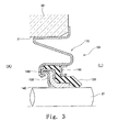
- Fig. 3 shows a second example of the present invention (showing only an intersected end face).
- a modification of the case in the first example will be described.
- the other constituent parts and their operations are the same as those in the first example, thus the same constituent parts are designated by the same reference signs as those in the first example, and the description thereof will be omitted.
- a sealing device 101 there may be a case where the size of the annular gap to be sealed by the sealing device becomes larger depending on the relation between the rotating shaft 21 and the inner diameter of the shaft hole 31 of the housing 30. Therefore, in a sealing device 101 according to the present example, a portion having an S-shaped cross section is provided in a case (cartridge) 170 to provide elasticity in the radial direction, and hence a sufficient sealing performance is exhibited even in the case of a large annular gap without degrading ease of attachment.
- the constituent parts other than the case 170 are as described in the first example, and hence the description thereof will be omitted.
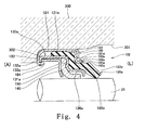
- Fig. 4 shows a third example of the present invention (showing only an intersected end face).
- the case of the sealing device abuts on a stepped surface provided in the shaft hole of the housing.
- the same constituent parts as those in the first example are designated by the same reference signs as those in the first example and the description thereof will be omitted.
- a sealing device 102 that is attached to a shaft hole 301 of a housing 300 includes a case (cartridge) 180 made of metal, a first sealing member 120a made of rubber-like elastomer, a swaging member 130a made of metal, the second sealing member 140 made of resin, and the backup ring 150 made of metal.
- the sealing device 102 includes an adaptor 160a as a positioning member that positions the first sealing member 120a in the axial direction.
- the outer peripheral surface of a cylindrical portion 181 is fitted in the inner peripheral surface of the shaft hole 301, and an inward flange portion 182 provided on the air side (A) of the cylindrical portion 181 abuts on a stepped surface 302 in the shaft hole 301.
- an angled portion 183 provided on the sealed fluid side (L) of the cylindrical portion 181 retains the adaptor 160a by pushing the adaptor 160a from the sealed fluid side (L).
- One or a plurality of engaging convex portions 184 that engage with notches 133a provided on a second flange portion 132a of the swaging member 130a are provided on the inward flange portion 182.
- the first sealing member 120a includes a body 121a and a first sealing lip 123a that is in slidable contact with the outer peripheral surface of the rotating shaft 21.
- the first sealing member 120a is a member substantially equivalent to the first sealing member 120 except that the first sealing member 120a does not have a constituent part corresponding to the annular convex portion 124 in the first sealing member 120 according to the first example.
- the swaging member 130a configured by an annular member is fitted.
- the swaging member 130a further includes an extended portion 136a that extends toward the sealed fluid side (L) from a first flange portion 131a along the inner peripheral side of the first sealing lip 123a.
- the extended portion 136a stabilizes the posture of the first sealing lip 123a by positioning the first sealing lip 123a from the inner peripheral side. Accordingly, the sealing performance of the first sealing member 120a is exhibited effectively.
- the swaging member 130a is a member substantially equivalent to the swaging member 130 according to the first example except that the swaging member 130a has the extended portion 136a. That is, the second sealing member 140 and the backup ring 150 are retained by swaging by the first flange portion 131a and the second flange portion 132a.
- a convex portion provided on the surface on the air side (A) of the first flange portion 131a prevents rotation relative to the second sealing member 140
- a concave portion provided on the surface on the sealed fluid side (L) prevents rotation relative to the first sealing member 120a.
- the adaptor 160a retained by the angled portion 183 of the case 180 has a bent portion 163a on the sealed fluid side (L) of the inner peripheral end portion of a positioning portion 161a.
- the bent portion 163a is a member substantially equivalent to the bent portion 163 according to the first example.
- An edge portion 165a at a tip 164a is bent toward the outer peripheral side so as to be spaced apart from the outer peripheral surface of the first sealing lip 123a and a contacting portion 166a that is positioned further to the inner peripheral side from the tip 164a is in surface contact with the outer peripheral surface of the first sealing lip 123a.
- the sealing device 102 effects equivalent to those of the sealing device 100 according to the first example are achieved as well. That is, because the adaptor 160a has the bent portion 163a provided with the contacting portion 166a that is in surface contact with the outer peripheral surface of the first sealing lip 123a, it is possible to position the first sealing lip 123a from the outer peripheral side. Accordingly, it is possible to stabilize the posture of the first sealing lip 123a and make the first sealing member 120a exhibit its sealing performance effectively.
- the edge portion 165a at the tip 164a of the bent portion 163a is bent toward the outer peripheral side so as to be spaced apart from the outer peripheral surface of the first sealing lip 123a.
- the sealing device 102 when the sealing device 102 is in a state in which it is attached to the housing 300, even when the first sealing lip 123a is deformed toward the outer peripheral side, the outer peripheral surface of the first sealing lip 123a is prevented from coming into contact with the edge portion 165a. Accordingly, it is possible to effectively suppress occurrence of damage such as a crack or the like to the outer peripheral surface of the first sealing lip 123a. Consequently, it is possible to maintain the sealing performance of the first sealing member 120a effectively.
- the sealing device is used in the water pump 10 for an automobile as the application example of the sealing device
- the present invention can be applied to various devices in which an annular gap between a shaft and a housing rotating relative to each other needs to be sealed.
- the present invention can be suitably used as a sealing device or sealing structure for a shaft seal in a device for home electronics or an industrial water pump having a low load.
Landscapes
- Engineering & Computer Science (AREA)
- General Engineering & Computer Science (AREA)
- Mechanical Engineering (AREA)
- Sealing With Elastic Sealing Lips (AREA)
- Sealing Devices (AREA)
Applications Claiming Priority (2)
| Application Number | Priority Date | Filing Date | Title |
|---|---|---|---|
| JP2012184388 | 2012-08-23 | ||
| PCT/JP2013/066714 WO2014030413A1 (ja) | 2012-08-23 | 2013-06-18 | 密封装置 |
Publications (3)
| Publication Number | Publication Date |
|---|---|
| EP2889518A1 true EP2889518A1 (de) | 2015-07-01 |
| EP2889518A4 EP2889518A4 (de) | 2016-04-06 |
| EP2889518B1 EP2889518B1 (de) | 2019-05-08 |
Family
ID=50149731
Family Applications (1)
| Application Number | Title | Priority Date | Filing Date |
|---|---|---|---|
| EP13830404.3A Active EP2889518B1 (de) | 2012-08-23 | 2013-06-18 | Dichtungsvorrichtung |
Country Status (5)
| Country | Link |
|---|---|
| US (1) | US9194498B2 (de) |
| EP (1) | EP2889518B1 (de) |
| JP (1) | JP6113733B2 (de) |
| CN (1) | CN104583653B (de) |
| WO (1) | WO2014030413A1 (de) |
Families Citing this family (8)
| Publication number | Priority date | Publication date | Assignee | Title |
|---|---|---|---|---|
| WO2016140709A1 (en) | 2015-03-05 | 2016-09-09 | Hewlett-Packard Development Company, L.P. | Selection of a digital content payoff based on identified mobile device type |
| CN104832652B (zh) * | 2015-04-15 | 2018-01-23 | 广州机械科学研究院有限公司 | 一种高压用油封组件 |
| JP6674229B2 (ja) * | 2015-11-05 | 2020-04-01 | 株式会社荒井製作所 | 密封装置 |
| CN108474479A (zh) * | 2016-01-13 | 2018-08-31 | Nok株式会社 | 密封装置 |
| JP7124057B2 (ja) * | 2018-03-15 | 2022-08-23 | イーグル工業株式会社 | シール装置 |
| JP7366915B2 (ja) * | 2018-09-11 | 2023-10-23 | イーグル工業株式会社 | リップ型軸封装置 |
| JP7530705B2 (ja) * | 2019-04-17 | 2024-08-08 | ナブテスコ株式会社 | シール構造 |
| KR102576874B1 (ko) * | 2019-06-11 | 2023-09-11 | 엔오케이 가부시키가이샤 | 밀봉장치 및 밀봉장치의 장착방법 |
Family Cites Families (12)
| Publication number | Priority date | Publication date | Assignee | Title |
|---|---|---|---|---|
| US2434484A (en) * | 1945-02-09 | 1948-01-13 | Garlock Packing Co | Oil seal |
| JPH0342279Y2 (de) * | 1987-11-12 | 1991-09-04 | ||
| JPH03269615A (ja) | 1990-03-19 | 1991-12-02 | Nec Corp | プリンタ |
| JP3177302B2 (ja) | 1992-06-29 | 2001-06-18 | 松山株式会社 | 収穫機 |
| JPH0614630U (ja) * | 1992-07-30 | 1994-02-25 | キーパー株式会社 | オイルシール |
| US6050572A (en) * | 1998-03-09 | 2000-04-18 | Bal Seal Engineering Company, Inc. | Rotary cartridge seals with retainer |
| JP4125905B2 (ja) * | 2002-03-14 | 2008-07-30 | 日本ピラー工業株式会社 | 密封構造 |
| EP1598579B1 (de) * | 2003-02-27 | 2008-05-14 | EAGLE INDUSTRY Co., Ltd. | Lippendichtung |
| US8256772B2 (en) | 2008-11-27 | 2012-09-04 | Eagle Industry Co., Ltd. | Lip type seal |
| EP2476934B1 (de) * | 2009-09-09 | 2015-08-26 | Eagle Industry Co., Ltd. | Lippendichtung |
| JP5626928B2 (ja) | 2010-09-11 | 2014-11-19 | イーグル工業株式会社 | 軸封装置 |
| WO2014030742A1 (ja) * | 2012-08-23 | 2014-02-27 | イーグル工業株式会社 | 密封装置 |
-
2013
- 2013-06-18 JP JP2014531530A patent/JP6113733B2/ja active Active
- 2013-06-18 CN CN201380043513.4A patent/CN104583653B/zh active Active
- 2013-06-18 US US14/422,208 patent/US9194498B2/en active Active
- 2013-06-18 EP EP13830404.3A patent/EP2889518B1/de active Active
- 2013-06-18 WO PCT/JP2013/066714 patent/WO2014030413A1/ja not_active Ceased
Also Published As
| Publication number | Publication date |
|---|---|
| CN104583653B (zh) | 2017-02-22 |
| US9194498B2 (en) | 2015-11-24 |
| WO2014030413A1 (ja) | 2014-02-27 |
| JPWO2014030413A1 (ja) | 2016-07-28 |
| EP2889518A4 (de) | 2016-04-06 |
| CN104583653A (zh) | 2015-04-29 |
| JP6113733B2 (ja) | 2017-04-12 |
| EP2889518B1 (de) | 2019-05-08 |
| US20150226330A1 (en) | 2015-08-13 |
Similar Documents
| Publication | Publication Date | Title |
|---|---|---|
| EP2889518A1 (de) | Dichtungsvorrichtung | |
| JP6208665B2 (ja) | 密封装置 | |
| JP5626928B2 (ja) | 軸封装置 | |
| EP3505799B1 (de) | Dichtungsvorrichtung | |
| EP2749796A1 (de) | Dichtungsvorrichtung | |
| JP2008281192A (ja) | シールリング | |
| US7942423B2 (en) | Lip type seal | |
| US20130228978A1 (en) | Sealing device and sealing structure | |
| EP3070379B1 (de) | Mechanische dichtung | |
| JP6456966B2 (ja) | メカニカルシール | |
| EP2865927B1 (de) | Dichtungsvorrichtung | |
| JP5066787B2 (ja) | 密封構造 | |
| JP2019095052A (ja) | 密封装置 | |
| EP2952788B1 (de) | Dichtungsvorrichtung | |
| US11835136B2 (en) | Sealing device | |
| US20080048400A1 (en) | Unitized seal with integral flanged sleeve | |
| JP2017089801A (ja) | デフサイド用の密封装置 | |
| JP2012154483A (ja) | シールリング | |
| US20140175757A1 (en) | Shaft seal with retention features and overmolded seal component | |
| JP2008286320A (ja) | 密封装置 |
Legal Events
| Date | Code | Title | Description |
|---|---|---|---|
| PUAI | Public reference made under article 153(3) epc to a published international application that has entered the european phase |
Free format text: ORIGINAL CODE: 0009012 |
|
| 17P | Request for examination filed |
Effective date: 20150225 |
|
| AK | Designated contracting states |
Kind code of ref document: A1 Designated state(s): AL AT BE BG CH CY CZ DE DK EE ES FI FR GB GR HR HU IE IS IT LI LT LU LV MC MK MT NL NO PL PT RO RS SE SI SK SM TR |
|
| AX | Request for extension of the european patent |
Extension state: BA ME |
|
| DAX | Request for extension of the european patent (deleted) | ||
| RA4 | Supplementary search report drawn up and despatched (corrected) |
Effective date: 20160309 |
|
| RIC1 | Information provided on ipc code assigned before grant |
Ipc: F16J 15/3228 20160101ALI20160303BHEP Ipc: F16J 15/3268 20160101ALI20160303BHEP Ipc: F16J 15/322 20160101ALI20160303BHEP Ipc: F16J 15/32 20060101AFI20160303BHEP Ipc: F16J 15/3232 20160101ALI20160303BHEP |
|
| STAA | Information on the status of an ep patent application or granted ep patent |
Free format text: STATUS: EXAMINATION IS IN PROGRESS |
|
| 17Q | First examination report despatched |
Effective date: 20170908 |
|
| GRAP | Despatch of communication of intention to grant a patent |
Free format text: ORIGINAL CODE: EPIDOSNIGR1 |
|
| STAA | Information on the status of an ep patent application or granted ep patent |
Free format text: STATUS: GRANT OF PATENT IS INTENDED |
|
| INTG | Intention to grant announced |
Effective date: 20181115 |
|
| RIC1 | Information provided on ipc code assigned before grant |
Ipc: F16J 15/3228 20160101ALI20160303BHEP Ipc: F16J 15/322 20160101ALI20160303BHEP Ipc: F16J 15/3268 20160101ALI20160303BHEP Ipc: F16J 15/3232 20160101ALI20160303BHEP Ipc: F16J 15/32 20160101AFI20160303BHEP |
|
| GRAS | Grant fee paid |
Free format text: ORIGINAL CODE: EPIDOSNIGR3 |
|
| GRAJ | Information related to disapproval of communication of intention to grant by the applicant or resumption of examination proceedings by the epo deleted |
Free format text: ORIGINAL CODE: EPIDOSDIGR1 |
|
| GRAL | Information related to payment of fee for publishing/printing deleted |
Free format text: ORIGINAL CODE: EPIDOSDIGR3 |
|
| STAA | Information on the status of an ep patent application or granted ep patent |
Free format text: STATUS: EXAMINATION IS IN PROGRESS |
|
| GRAR | Information related to intention to grant a patent recorded |
Free format text: ORIGINAL CODE: EPIDOSNIGR71 |
|
| STAA | Information on the status of an ep patent application or granted ep patent |
Free format text: STATUS: GRANT OF PATENT IS INTENDED |
|
| GRAA | (expected) grant |
Free format text: ORIGINAL CODE: 0009210 |
|
| STAA | Information on the status of an ep patent application or granted ep patent |
Free format text: STATUS: THE PATENT HAS BEEN GRANTED |
|
| INTC | Intention to grant announced (deleted) | ||
| INTG | Intention to grant announced |
Effective date: 20190328 |
|
| AK | Designated contracting states |
Kind code of ref document: B1 Designated state(s): AL AT BE BG CH CY CZ DE DK EE ES FI FR GB GR HR HU IE IS IT LI LT LU LV MC MK MT NL NO PL PT RO RS SE SI SK SM TR |
|
| REG | Reference to a national code |
Ref country code: GB Ref legal event code: FG4D |
|
| REG | Reference to a national code |
Ref country code: CH Ref legal event code: EP Ref country code: AT Ref legal event code: REF Ref document number: 1130648 Country of ref document: AT Kind code of ref document: T Effective date: 20190515 |
|
| REG | Reference to a national code |
Ref country code: DE Ref legal event code: R096 Ref document number: 602013055193 Country of ref document: DE Ref country code: IE Ref legal event code: FG4D |
|
| REG | Reference to a national code |
Ref country code: NL Ref legal event code: MP Effective date: 20190508 |
|
| REG | Reference to a national code |
Ref country code: LT Ref legal event code: MG4D |
|
| PG25 | Lapsed in a contracting state [announced via postgrant information from national office to epo] |
Ref country code: PT Free format text: LAPSE BECAUSE OF FAILURE TO SUBMIT A TRANSLATION OF THE DESCRIPTION OR TO PAY THE FEE WITHIN THE PRESCRIBED TIME-LIMIT Effective date: 20190908 Ref country code: AL Free format text: LAPSE BECAUSE OF FAILURE TO SUBMIT A TRANSLATION OF THE DESCRIPTION OR TO PAY THE FEE WITHIN THE PRESCRIBED TIME-LIMIT Effective date: 20190508 Ref country code: SE Free format text: LAPSE BECAUSE OF FAILURE TO SUBMIT A TRANSLATION OF THE DESCRIPTION OR TO PAY THE FEE WITHIN THE PRESCRIBED TIME-LIMIT Effective date: 20190508 Ref country code: ES Free format text: LAPSE BECAUSE OF FAILURE TO SUBMIT A TRANSLATION OF THE DESCRIPTION OR TO PAY THE FEE WITHIN THE PRESCRIBED TIME-LIMIT Effective date: 20190508 Ref country code: HR Free format text: LAPSE BECAUSE OF FAILURE TO SUBMIT A TRANSLATION OF THE DESCRIPTION OR TO PAY THE FEE WITHIN THE PRESCRIBED TIME-LIMIT Effective date: 20190508 Ref country code: LT Free format text: LAPSE BECAUSE OF FAILURE TO SUBMIT A TRANSLATION OF THE DESCRIPTION OR TO PAY THE FEE WITHIN THE PRESCRIBED TIME-LIMIT Effective date: 20190508 Ref country code: FI Free format text: LAPSE BECAUSE OF FAILURE TO SUBMIT A TRANSLATION OF THE DESCRIPTION OR TO PAY THE FEE WITHIN THE PRESCRIBED TIME-LIMIT Effective date: 20190508 Ref country code: NO Free format text: LAPSE BECAUSE OF FAILURE TO SUBMIT A TRANSLATION OF THE DESCRIPTION OR TO PAY THE FEE WITHIN THE PRESCRIBED TIME-LIMIT Effective date: 20190808 Ref country code: NL Free format text: LAPSE BECAUSE OF FAILURE TO SUBMIT A TRANSLATION OF THE DESCRIPTION OR TO PAY THE FEE WITHIN THE PRESCRIBED TIME-LIMIT Effective date: 20190508 |
|
| PG25 | Lapsed in a contracting state [announced via postgrant information from national office to epo] |
Ref country code: LV Free format text: LAPSE BECAUSE OF FAILURE TO SUBMIT A TRANSLATION OF THE DESCRIPTION OR TO PAY THE FEE WITHIN THE PRESCRIBED TIME-LIMIT Effective date: 20190508 Ref country code: RS Free format text: LAPSE BECAUSE OF FAILURE TO SUBMIT A TRANSLATION OF THE DESCRIPTION OR TO PAY THE FEE WITHIN THE PRESCRIBED TIME-LIMIT Effective date: 20190508 Ref country code: GR Free format text: LAPSE BECAUSE OF FAILURE TO SUBMIT A TRANSLATION OF THE DESCRIPTION OR TO PAY THE FEE WITHIN THE PRESCRIBED TIME-LIMIT Effective date: 20190809 Ref country code: BG Free format text: LAPSE BECAUSE OF FAILURE TO SUBMIT A TRANSLATION OF THE DESCRIPTION OR TO PAY THE FEE WITHIN THE PRESCRIBED TIME-LIMIT Effective date: 20190808 |
|
| REG | Reference to a national code |
Ref country code: AT Ref legal event code: MK05 Ref document number: 1130648 Country of ref document: AT Kind code of ref document: T Effective date: 20190508 |
|
| PG25 | Lapsed in a contracting state [announced via postgrant information from national office to epo] |
Ref country code: DK Free format text: LAPSE BECAUSE OF FAILURE TO SUBMIT A TRANSLATION OF THE DESCRIPTION OR TO PAY THE FEE WITHIN THE PRESCRIBED TIME-LIMIT Effective date: 20190508 Ref country code: SK Free format text: LAPSE BECAUSE OF FAILURE TO SUBMIT A TRANSLATION OF THE DESCRIPTION OR TO PAY THE FEE WITHIN THE PRESCRIBED TIME-LIMIT Effective date: 20190508 Ref country code: AT Free format text: LAPSE BECAUSE OF FAILURE TO SUBMIT A TRANSLATION OF THE DESCRIPTION OR TO PAY THE FEE WITHIN THE PRESCRIBED TIME-LIMIT Effective date: 20190508 Ref country code: CZ Free format text: LAPSE BECAUSE OF FAILURE TO SUBMIT A TRANSLATION OF THE DESCRIPTION OR TO PAY THE FEE WITHIN THE PRESCRIBED TIME-LIMIT Effective date: 20190508 Ref country code: EE Free format text: LAPSE BECAUSE OF FAILURE TO SUBMIT A TRANSLATION OF THE DESCRIPTION OR TO PAY THE FEE WITHIN THE PRESCRIBED TIME-LIMIT Effective date: 20190508 Ref country code: RO Free format text: LAPSE BECAUSE OF FAILURE TO SUBMIT A TRANSLATION OF THE DESCRIPTION OR TO PAY THE FEE WITHIN THE PRESCRIBED TIME-LIMIT Effective date: 20190508 |
|
| REG | Reference to a national code |
Ref country code: CH Ref legal event code: PL |
|
| REG | Reference to a national code |
Ref country code: DE Ref legal event code: R097 Ref document number: 602013055193 Country of ref document: DE |
|
| PG25 | Lapsed in a contracting state [announced via postgrant information from national office to epo] |
Ref country code: MC Free format text: LAPSE BECAUSE OF FAILURE TO SUBMIT A TRANSLATION OF THE DESCRIPTION OR TO PAY THE FEE WITHIN THE PRESCRIBED TIME-LIMIT Effective date: 20190508 Ref country code: SM Free format text: LAPSE BECAUSE OF FAILURE TO SUBMIT A TRANSLATION OF THE DESCRIPTION OR TO PAY THE FEE WITHIN THE PRESCRIBED TIME-LIMIT Effective date: 20190508 Ref country code: IT Free format text: LAPSE BECAUSE OF FAILURE TO SUBMIT A TRANSLATION OF THE DESCRIPTION OR TO PAY THE FEE WITHIN THE PRESCRIBED TIME-LIMIT Effective date: 20190508 |
|
| PLBE | No opposition filed within time limit |
Free format text: ORIGINAL CODE: 0009261 |
|
| STAA | Information on the status of an ep patent application or granted ep patent |
Free format text: STATUS: NO OPPOSITION FILED WITHIN TIME LIMIT |
|
| REG | Reference to a national code |
Ref country code: BE Ref legal event code: MM Effective date: 20190630 |
|
| PG25 | Lapsed in a contracting state [announced via postgrant information from national office to epo] |
Ref country code: TR Free format text: LAPSE BECAUSE OF FAILURE TO SUBMIT A TRANSLATION OF THE DESCRIPTION OR TO PAY THE FEE WITHIN THE PRESCRIBED TIME-LIMIT Effective date: 20190508 |
|
| 26N | No opposition filed |
Effective date: 20200211 |
|
| GBPC | Gb: european patent ceased through non-payment of renewal fee |
Effective date: 20190808 |
|
| PG25 | Lapsed in a contracting state [announced via postgrant information from national office to epo] |
Ref country code: PL Free format text: LAPSE BECAUSE OF FAILURE TO SUBMIT A TRANSLATION OF THE DESCRIPTION OR TO PAY THE FEE WITHIN THE PRESCRIBED TIME-LIMIT Effective date: 20190508 Ref country code: IE Free format text: LAPSE BECAUSE OF NON-PAYMENT OF DUE FEES Effective date: 20190618 |
|
| PG25 | Lapsed in a contracting state [announced via postgrant information from national office to epo] |
Ref country code: LU Free format text: LAPSE BECAUSE OF NON-PAYMENT OF DUE FEES Effective date: 20190618 Ref country code: BE Free format text: LAPSE BECAUSE OF NON-PAYMENT OF DUE FEES Effective date: 20190630 Ref country code: CH Free format text: LAPSE BECAUSE OF NON-PAYMENT OF DUE FEES Effective date: 20190630 Ref country code: LI Free format text: LAPSE BECAUSE OF NON-PAYMENT OF DUE FEES Effective date: 20190630 Ref country code: SI Free format text: LAPSE BECAUSE OF FAILURE TO SUBMIT A TRANSLATION OF THE DESCRIPTION OR TO PAY THE FEE WITHIN THE PRESCRIBED TIME-LIMIT Effective date: 20190508 |
|
| PG25 | Lapsed in a contracting state [announced via postgrant information from national office to epo] |
Ref country code: FR Free format text: LAPSE BECAUSE OF NON-PAYMENT OF DUE FEES Effective date: 20190708 |
|
| PG25 | Lapsed in a contracting state [announced via postgrant information from national office to epo] |
Ref country code: GB Free format text: LAPSE BECAUSE OF NON-PAYMENT OF DUE FEES Effective date: 20190808 |
|
| PG25 | Lapsed in a contracting state [announced via postgrant information from national office to epo] |
Ref country code: CY Free format text: LAPSE BECAUSE OF FAILURE TO SUBMIT A TRANSLATION OF THE DESCRIPTION OR TO PAY THE FEE WITHIN THE PRESCRIBED TIME-LIMIT Effective date: 20190508 |
|
| PG25 | Lapsed in a contracting state [announced via postgrant information from national office to epo] |
Ref country code: IS Free format text: LAPSE BECAUSE OF FAILURE TO SUBMIT A TRANSLATION OF THE DESCRIPTION OR TO PAY THE FEE WITHIN THE PRESCRIBED TIME-LIMIT Effective date: 20190908 |
|
| PG25 | Lapsed in a contracting state [announced via postgrant information from national office to epo] |
Ref country code: HU Free format text: LAPSE BECAUSE OF FAILURE TO SUBMIT A TRANSLATION OF THE DESCRIPTION OR TO PAY THE FEE WITHIN THE PRESCRIBED TIME-LIMIT; INVALID AB INITIO Effective date: 20130618 Ref country code: MT Free format text: LAPSE BECAUSE OF FAILURE TO SUBMIT A TRANSLATION OF THE DESCRIPTION OR TO PAY THE FEE WITHIN THE PRESCRIBED TIME-LIMIT Effective date: 20190508 |
|
| PG25 | Lapsed in a contracting state [announced via postgrant information from national office to epo] |
Ref country code: MK Free format text: LAPSE BECAUSE OF FAILURE TO SUBMIT A TRANSLATION OF THE DESCRIPTION OR TO PAY THE FEE WITHIN THE PRESCRIBED TIME-LIMIT Effective date: 20190508 |
|
| PGFP | Annual fee paid to national office [announced via postgrant information from national office to epo] |
Ref country code: DE Payment date: 20250429 Year of fee payment: 13 |