EP2887202A1 - Wartungsmonitorvorrichtung, programm dafür und aufzeichnungsmedium - Google Patents
Wartungsmonitorvorrichtung, programm dafür und aufzeichnungsmedium Download PDFInfo
- Publication number
- EP2887202A1 EP2887202A1 EP13853408.6A EP13853408A EP2887202A1 EP 2887202 A1 EP2887202 A1 EP 2887202A1 EP 13853408 A EP13853408 A EP 13853408A EP 2887202 A1 EP2887202 A1 EP 2887202A1
- Authority
- EP
- European Patent Office
- Prior art keywords
- display
- graph
- numerical data
- maintenance
- cursor
- Prior art date
- Legal status (The legal status is an assumption and is not a legal conclusion. Google has not performed a legal analysis and makes no representation as to the accuracy of the status listed.)
- Granted
Links
- 238000012423 maintenance Methods 0.000 title claims abstract description 60
- 238000000034 method Methods 0.000 claims description 11
- 239000000498 cooling water Substances 0.000 description 7
- 230000001133 acceleration Effects 0.000 description 3
- 238000010586 diagram Methods 0.000 description 3
- 238000000746 purification Methods 0.000 description 3
- 239000000446 fuel Substances 0.000 description 2
- 238000002347 injection Methods 0.000 description 2
- 239000007924 injection Substances 0.000 description 2
- 238000007796 conventional method Methods 0.000 description 1
- 239000000463 material Substances 0.000 description 1
- 238000005259 measurement Methods 0.000 description 1
- 238000012986 modification Methods 0.000 description 1
- 230000004048 modification Effects 0.000 description 1
- 238000012545 processing Methods 0.000 description 1
- 239000000243 solution Substances 0.000 description 1
Images


Classifications
-
- G—PHYSICS
- G07—CHECKING-DEVICES
- G07C—TIME OR ATTENDANCE REGISTERS; REGISTERING OR INDICATING THE WORKING OF MACHINES; GENERATING RANDOM NUMBERS; VOTING OR LOTTERY APPARATUS; ARRANGEMENTS, SYSTEMS OR APPARATUS FOR CHECKING NOT PROVIDED FOR ELSEWHERE
- G07C5/00—Registering or indicating the working of vehicles
- G07C5/08—Registering or indicating performance data other than driving, working, idle, or waiting time, with or without registering driving, working, idle or waiting time
- G07C5/0816—Indicating performance data, e.g. occurrence of a malfunction
- G07C5/0825—Indicating performance data, e.g. occurrence of a malfunction using optical means
-
- G—PHYSICS
- G06—COMPUTING; CALCULATING OR COUNTING
- G06F—ELECTRIC DIGITAL DATA PROCESSING
- G06F3/00—Input arrangements for transferring data to be processed into a form capable of being handled by the computer; Output arrangements for transferring data from processing unit to output unit, e.g. interface arrangements
- G06F3/01—Input arrangements or combined input and output arrangements for interaction between user and computer
- G06F3/048—Interaction techniques based on graphical user interfaces [GUI]
-
- G—PHYSICS
- G01—MEASURING; TESTING
- G01D—MEASURING NOT SPECIALLY ADAPTED FOR A SPECIFIC VARIABLE; ARRANGEMENTS FOR MEASURING TWO OR MORE VARIABLES NOT COVERED IN A SINGLE OTHER SUBCLASS; TARIFF METERING APPARATUS; MEASURING OR TESTING NOT OTHERWISE PROVIDED FOR
- G01D7/00—Indicating measured values
- G01D7/02—Indicating value of two or more variables simultaneously
- G01D7/04—Indicating value of two or more variables simultaneously using a separate indicating element for each variable
-
- G—PHYSICS
- G06—COMPUTING; CALCULATING OR COUNTING
- G06F—ELECTRIC DIGITAL DATA PROCESSING
- G06F3/00—Input arrangements for transferring data to be processed into a form capable of being handled by the computer; Output arrangements for transferring data from processing unit to output unit, e.g. interface arrangements
- G06F3/01—Input arrangements or combined input and output arrangements for interaction between user and computer
- G06F3/048—Interaction techniques based on graphical user interfaces [GUI]
- G06F3/0481—Interaction techniques based on graphical user interfaces [GUI] based on specific properties of the displayed interaction object or a metaphor-based environment, e.g. interaction with desktop elements like windows or icons, or assisted by a cursor's changing behaviour or appearance
- G06F3/04812—Interaction techniques based on cursor appearance or behaviour, e.g. being affected by the presence of displayed objects
-
- G—PHYSICS
- G06—COMPUTING; CALCULATING OR COUNTING
- G06F—ELECTRIC DIGITAL DATA PROCESSING
- G06F3/00—Input arrangements for transferring data to be processed into a form capable of being handled by the computer; Output arrangements for transferring data from processing unit to output unit, e.g. interface arrangements
- G06F3/01—Input arrangements or combined input and output arrangements for interaction between user and computer
- G06F3/048—Interaction techniques based on graphical user interfaces [GUI]
- G06F3/0481—Interaction techniques based on graphical user interfaces [GUI] based on specific properties of the displayed interaction object or a metaphor-based environment, e.g. interaction with desktop elements like windows or icons, or assisted by a cursor's changing behaviour or appearance
- G06F3/0482—Interaction with lists of selectable items, e.g. menus
-
- G—PHYSICS
- G06—COMPUTING; CALCULATING OR COUNTING
- G06F—ELECTRIC DIGITAL DATA PROCESSING
- G06F3/00—Input arrangements for transferring data to be processed into a form capable of being handled by the computer; Output arrangements for transferring data from processing unit to output unit, e.g. interface arrangements
- G06F3/01—Input arrangements or combined input and output arrangements for interaction between user and computer
- G06F3/048—Interaction techniques based on graphical user interfaces [GUI]
- G06F3/0484—Interaction techniques based on graphical user interfaces [GUI] for the control of specific functions or operations, e.g. selecting or manipulating an object, an image or a displayed text element, setting a parameter value or selecting a range
- G06F3/04842—Selection of displayed objects or displayed text elements
-
- G—PHYSICS
- G07—CHECKING-DEVICES
- G07C—TIME OR ATTENDANCE REGISTERS; REGISTERING OR INDICATING THE WORKING OF MACHINES; GENERATING RANDOM NUMBERS; VOTING OR LOTTERY APPARATUS; ARRANGEMENTS, SYSTEMS OR APPARATUS FOR CHECKING NOT PROVIDED FOR ELSEWHERE
- G07C5/00—Registering or indicating the working of vehicles
- G07C5/08—Registering or indicating performance data other than driving, working, idle, or waiting time, with or without registering driving, working, idle or waiting time
- G07C5/0808—Diagnosing performance data
-
- G—PHYSICS
- G07—CHECKING-DEVICES
- G07C—TIME OR ATTENDANCE REGISTERS; REGISTERING OR INDICATING THE WORKING OF MACHINES; GENERATING RANDOM NUMBERS; VOTING OR LOTTERY APPARATUS; ARRANGEMENTS, SYSTEMS OR APPARATUS FOR CHECKING NOT PROVIDED FOR ELSEWHERE
- G07C5/00—Registering or indicating the working of vehicles
- G07C5/08—Registering or indicating performance data other than driving, working, idle, or waiting time, with or without registering driving, working, idle or waiting time
- G07C5/12—Registering or indicating performance data other than driving, working, idle, or waiting time, with or without registering driving, working, idle or waiting time in graphical form
-
- G—PHYSICS
- G06—COMPUTING; CALCULATING OR COUNTING
- G06F—ELECTRIC DIGITAL DATA PROCESSING
- G06F3/00—Input arrangements for transferring data to be processed into a form capable of being handled by the computer; Output arrangements for transferring data from processing unit to output unit, e.g. interface arrangements
- G06F3/14—Digital output to display device ; Cooperation and interconnection of the display device with other functional units
Definitions
- the present disclosure relates to a maintenance monitor device capable of simultaneously displaying numerical data of three or more display items on a graph, and a program and a recording medium for the maintenance monitor device. It preferably relates to a maintenance monitor device, in particular, used for maintenance of a diesel engine mounted on an industrial vehicle, and a program and a recording medium for the maintenance monitor device.
- a maintenance monitor device when carrying out maintenance on various apparatuses such as a diesel engine, a maintenance monitor device is used to monitor the operation state of the apparatus in real time.
- the maintenance monitor device displays measurement values or the like that indicate the operation state of the apparatus on a monitor screen in real time.
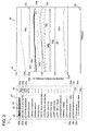
- FIG. 5 is a diagram of a monitor screen displayed by a conventional monitor device.
- a graph with the x-axis indicating time is displayed.
- displayed are numerical data of a plurality of display items, such as the engine rotation speed (a), the acceleration opening degree (b), the cooling water temperature (c), the boost pressure (d), the intake temperature (e), the rail pressure (f), and the total fuel injection amount (g), associated with the graph axes.
- scales, names, and units are displayed on the y-axis of the graph, corresponding to the plurality of display items (a) to (g) described above.
- Patent Document 1 Japanese Unexamined Patent Application Pub. No. 2008-209511
- the above conventional monitor device displays scales, names, units corresponding to the plurality of display items on the Y-axis next to one another.
- the time axis becomes short in turn, narrowing the display region of the graph, which is also a disadvantage in terms of visibility.
- two or more display items are visually monitored at the same time, such as the engine rotation speed and the acceleration opening degree, and the engine rotation speed and the total fuel injection amount. Also, the display items are frequently switched. Thus, operability upon changing the graph display is also required for the monitor device, in addition to the above described visibility.
- Patent Document 1 discloses a display-scale changing system that can change the scales of the graph when more than one display item is displayed on a graph.
- this display-scale changing system of Patent Document 1 requires frequent click and drag operations of a computer mouse, and therefore adept skills for operating the system.
- At least one embodiment of the present invention was made in view of the above issues of the conventional technique, and an object is to provide a maintenance monitor device capable of displaying numerical data of three or more display items on a graph at the same time, with high visibility and operability.
- At least one embodiment of a maintenance monitor device is a maintenance monitor device capable of displaying a graph of numerical data of three or more of a plurality of display items related to an apparatus subject to maintenance on a monitor screen.
- the maintenance monitor device includes: a list display unit capable of displaying a list of the display items on the monitor screen; a numerical data display unit configured to be capable of displaying a graph of numerical data related to the three or more display items on the monitor screen in accordance with graph axes including a first axis which includes a time axis; a position information calculation unit configured to be capable of calculating position information of a cursor displayed on the monitor screen; a display item recognition unit configured to be capable of recognizing the display items indicated by the cursor on the basis of the position information of the cursor calculated by the position information calculation unit; and a second axis display unit configured to be capable of displaying only one scale corresponding to the display item recognized by the display item recognition unit on a second axis included in the graph axes.
- the visibility is enhanced because only one scale is displayed on the second axis of the graph axes. Further, since the display item indicated by the cursor is recognized on the basis of the position information of the cursor, it is possible to display the single corresponding scale by a simple operation of only superposing the position of the cursor on one of the display items or the graph lines displayed on the monitor screen. Thus, the operability is also enhanced.
- the display item recognition unit is configured to recognize, from the list of the display items displayed on the monitor screen, one of the display items indicated by the cursor.
- the display item recognition unit is configured to recognize, from among graph lines corresponding to the three or more display items of the graph displayed on the monitor screen, one of the display items which corresponds to one of the graph lines indicated by the cursor.
- one embodiment of the present invention further includes a display item selection unit configured to be capable of optionally selecting three or more display items from the list of the display items.
- the numerical data display unit is configured to display the graph of only the numerical data of the selected display items selected by the display item selection unit.
- the display item recognition unit is configured to recognize one of the selected display items selected by the display item selection unit.
- the display item recognition unit configured to recognize only the selected display items selected by the display item selection unit, it is possible to reduce the frequency of displaying an unintended scale on the second axis due to operation error of the computer mouse. Thus, the operability is enhanced.
- the numerical data display unit is configured to indicate, on the graph, the numerical data of the display item recognized by the display item recognition unit by a graph line varied from the other numerical data.
- the second axis display unit is configured to maintain a tick-mark interval of the scale to be constant regardless of the display item recognized by the display item recognition unit.
- the tick-mark interval of the scale is kept constant even when the scale displayed on the second axis is switched to another scale.
- it is possible to improve the visibility of the graph upon switching the scales.
- the apparatus subject to maintenance is a diesel engine mounted on an industrial vehicle.
- the above maintenance monitor device is particularly suitable as a maintenance monitor device for a diesel engine mounted to an industrial vehicle such as a forklift.
- a diesel engine has many display items, and in a diesel engine, three or more of the display items are visually checked at the same time during maintenance, or the display items are frequently switched.
- At least one embodiment of the program of the present invention is a program for displaying a graph of numerical data of three or more display items related to an apparatus subject to maintenance simultaneously on a monitor screen.
- the program makes a computer execute: a list display process of displaying a list of the display items on the monitor screen; a numerical data display process of displaying a graph of numerical data related to the three or more display items on the monitor screen in accordance with graph axes including a first axis which includes a time axis; a position information calculation process of calculating position information of a cursor displayed on the monitor screen; a display item recognition process of recognizing the display items indicated by the cursor on the basis of the position information of the cursor calculated by the position information calculation unit; and a second axis display process of displaying only one scale corresponding to the display item recognized by the display item recognition unit on a second axis included in the graph axes.
- the visibility is enhanced because only one scale is displayed on the second axis of the graph axes. Further, since the display item indicated by the cursor is recognized on the basis of the position information of the cursor, it is possible to display the single corresponding scale by a simple operation of only superposing the position of the cursor on one of the display items or the graph lines displayed on the monitor screen. Thus, the operability is also enhanced.
- At least one embodiment of the present invention includes a recording medium storing the above program, the recording medium being readable by a computer.
- a maintenance monitor device capable of displaying numerical data of three or more display items on a graph at the same time, with high visibility and operability.
- a maintenance monitor device 1 is configured as, for instance, a micro computer including a central processing unit (CPU), a random access memory (RAM), a read only memory (ROM), and an I/O interface. Also, the maintenance monitor device 1 is configured to display a graph of numerical data of display items related to an apparatus subject to maintenance, on a monitor screen 10. Further, the apparatus subject to maintenance in the present embodiment is, for instance, a diesel engine 14 mounted to an industrial vehicle such as a forklift.
- FIG. 1 is a block diagram illustrating components of a maintenance monitor device according to one embodiment of the present invention.
- the maintenance monitor device 1 of the present embodiment includes a list display unit 2, a numerical data display unit 3, a display item selection unit 4, a second axis display unit 5, a display item recognition unit 6, and a position information calculation unit 7.
- FIGs. 2 and 3 are each an illustration of a monitor screen of the maintenance monitor device according to the present embodiment.
- a list display section 20 for displaying a list of display items 22 is formed on the left of the monitor screen 10. Further, a graph display section 30 for displaying a graph of numerical data of three or more of the display items 22 at the same time is formed on the right of the monitor screen 10.
- the list display unit 2 is configured to be capable of displaying a list of all display items 22 (display items 22a to 22s) of the diesel engine 14, on the list display section 20 of the above monitor screen 10. Further, the list display section 20 displays legend lines 24a to 24s of the same line type and color as those of the graph lines 34a to 34s, in accordance with the display items 22a to 22s, respectively. In this way, it is possible to recognize the correspondence relationship between the graph lines 34a to 34s displayed on the graph display section 30 and the display items 22a to 22s.
- the numerical data display unit 3 is configured to be capable of displaying the numerical data of the display items 22 transmitted from the engine control unit (ECU) 14a as the graph lines 34 on the graph display section 30 of the monitor screen 10.
- the graph lines 34 are displayed associated with graph axes including the first axis (for instance, x axis) being a time axis 32, and the second axis (for instance, y axis) being a scale 33.
- the scale 33 here corresponds to the engine rotation speed 22a.
- the numerical data display unit 3 may be configured to display only the graph lines 34 corresponding to display items 22 selected by a display item selection unit 4 described below, which are the selected display items. For instance, in FIG. 2 , a graph line 34a corresponding to the engine rotation speed 22a, a graph line 34b corresponding to the acceleration opening degree 22b, a graph line 34c corresponding to the cooling water temperature 22c, and the like are displayed as the graph lines 34 corresponding to the selected display items 22. With this configuration, it is possible to select only the display items 22 that need to be monitored, which enhances the visibility of the graph.
- the numerical data display unit 3 may be configured to display a graph of the numerical data of the display item 22 recognized by a display item recognition unit 6 described below by a graph line varied from those of the other numerical data. For instance, in FIG. 2 , only the graph line 34a corresponding to the engine rotation speed 22a, which is recognized by the display item recognition unit 6, is indicated thicker than the other graph lines 34. Further, in FIG. 3 , only the graph line 34c corresponding to the cooling water temperature 22c, which is recognized by the display item recognition unit 6, is indicated thicker than the other graph lines 34.
- the display item selection unit 4 is configured to be capable of optionally selecting three or more items from the above list of the display items 22. Specifically, on the left of the list display section 20, check boxes 26a to 26s are displayed corresponding to the display items 22a to 22s, so that three or more display items 22 are optionally selected by placing check marks on the check boxes 26.
- the second axis display unit 5 is configured to display only the scale 33 corresponding to one of the display items 22 that is selected by a user, on the second axis of the graph axes displayed on the above graph display section 30. For instance, in FIG. 2 , only the scale 33 corresponding to the engine rotation speed 22a is displayed. Further, in FIG. 3 , only the scale 33 corresponding to the cooling water temperature 22c is displayed.
- the scale 33 here includes at least one scale marking 33a and unit 33b, and preferably further includes a scale grid 33c that is displayed so as to correspond to the scale marking 33a and an item name 33d of the display item 22 being displayed, so that the scale on the axis can be understood.
- the second axis display unit 5 may be configured to maintain the display width 33e of the scale 33 to be constant regardless of the display item 22 recognized by the following display item recognition unit 6.
- the display width 33e of the scale 33 corresponding to the engine rotation speed 22a illustrated in FIG. 2 has an identical width to that of the display width 33e of the scale 33 corresponding to the cooling water temperature 22c illustrated in FIG. 3 .
- the display width of the scale 33 is kept identical even when the scale 33 displayed on the second axis has been switched, which makes it possible to improve the visibility of the graph upon switching the scale 33.
- the display item recognition unit 6 is configured to be capable of recognizing one of the display items 22 that is indicated by a cursor 28 displayed on the monitor screen 10, only on the basis of the position information of the cursor 28. Specifically, the cursor 28 moves on the monitor screen 10 as a result of operation of the computer mouse by the user, and when the position of the cursor 28 overlaps with one of the display items 22 displayed on the list display section 20, the display item recognition unit 6 immediately recognizes that the cursor 28 is pointing the one display item 22 even if there is no other specific operation such as a click. Then, the display item recognition unit 6 transmits the recognized display item 22 to the above second axis display unit 5.
- the display item recognition unit 6 may be configured to recognize only the display items 22 selected by the display item selection unit 4. Since the maintenance monitor device 1 of the present embodiment is configured to change the scale 33 that is to be displayed on the second axis only on the basis of the position information of the cursor 28, even a slight movement of the position of the cursor 28 may change what is displayed as the scale 33. Thus, with the display item recognition unit 6 configured to recognize only the display items 22 selected by the display item selection unit 4, it is possible to reduce the frequency of displaying an unintended scale due to an operation error of the computer mouse 12, thereby improving the operability.
- FIG. 2 illustrates the cursor 28 overlapping with the engine rotation speed 22a.
- FIG 3 illustrates the cursor 28 overlapping with the cooling water temperature 22c.
- only one of the display items 22 that is recognized by the display item recognition unit 6 may be displayed in a different way from the other display items 22 so as to easily distinguish the recognized display item 22 from the other display items 22. For instance, bold fonts may be used to emphasize the recognized display item 22.
- the position information calculation unit 7 is configured to be capable of calculating the position information of the cursor 28 displayed on the monitor screen 10. The calculated position information of the cursor 28 is then transmitted to the above display item recognition unit 6.
- FIG. 4 is a flowchart of an operation flow for switching a scale that is to be displayed on the second axis, in the maintenance monitor device according to the present embodiment.
- the above position information calculation unit 7 calculates the position information of the cursor 28 (S2). Then, on the basis of the calculated position information, the display item recognition unit 6 determines whether the position of the cursor 28 overlaps with one of the display items 22 displayed on the list display section 20 (S3), and whether the display item 22 with which the cursor 28 overlaps is one of the selected display items 22 selected by the above display item selection unit 4 (S4).
- the display item recognition unit 6 recognizes the single display item 22 pointed by the cursor 28 (S5). Then, the second axis display unit 5 displays a scale 33 that corresponds to the single display item 22 recognized by the display item recognition unit 6, on the second axis of the graph axes (S6).
- the maintenance monitor device 1 of the present embodiment is configured to execute the above operation flow every time the cursor 28 moves. At this time, unless the position of the cursor 28 freshly overlaps with another display item 22 displayed on the list display section 20, the scale 33 corresponding to the single display item 22 having been most recently recognized is continuously displayed on the second axis of the graph axes even if the cursor 28 moves.
- the above maintenance monitor device 1 has high visibility of the graph because only one scale 33 is displayed on the second axis of the graph axes. Further, the operability is also enhanced, as it is possible to display the scale 33 corresponding to an optional one of the display items 22 on the monitor screen 10 by a simple operation of only superposing the position of the cursor 28 on the optional display item 22 because the display item 22 indicated by the cursor 28 is recognized only on the basis of the position information of the cursor 28.
- the display item recognition unit 6 is configured to recognize one of the display items 22 that is indicated by the cursor 28, from the list of the display items 22 displayed on the monitor screen 10.
- the display item recognition unit 6 of the present invention is not limited this.
- the display item recognition unit 6 may be configured to recognize one of the display items 22 that corresponds to one of the graph lines 34 indicated by the cursor 28 from among the plurality of graph lines 34 displayed on the monitor screen 10, as the display item 22 indicated by the cursor 28.
- the maintenance monitor device 1 of the above embodiment is configured as a micro computer including a laptop computer.
- At least one embodiment of the present invention may be a program configured to make a computer execute various processes executed by the above list display unit 2, the numerical data display unit 3, the display item selection unit 4, the second axis display unit 5, the display item recognition unit 6, and the position information calculation unit 7.
- At least one embodiment of the present invention may be a recording medium that stores the above described program, and that is readable by a computer. With this configuration, it is possible to distribute the above program in a state of being stored in the recording medium.
- the apparatus subject to maintenance is illustrated as the diesel engine 14 mounted to an industrial vehicle such as a forklift, the present invention is not limited to this. Still, the maintenance monitor device 1 of the present embodiment is particularly suitable to be used for the diesel engine 14 mounted to an industrial vehicle such as a forklift, which has a large number of display items 22, and in which three or more display items are visually checked at the same time during maintenance and the display items 22 are frequently switched.
- At least one embodiment of the present invention as a maintenance monitor device capable of displaying a graph of numerical data of three or more display items at the same time, is particularly suitable to be used during maintenance of a diesel engine mounted on an industrial vehicle.
Landscapes
- Engineering & Computer Science (AREA)
- Physics & Mathematics (AREA)
- General Physics & Mathematics (AREA)
- General Engineering & Computer Science (AREA)
- Theoretical Computer Science (AREA)
- Human Computer Interaction (AREA)
- Controls And Circuits For Display Device (AREA)
- User Interface Of Digital Computer (AREA)
Applications Claiming Priority (2)
| Application Number | Priority Date | Filing Date | Title |
|---|---|---|---|
| JP2012246750A JP6103890B2 (ja) | 2012-11-08 | 2012-11-08 | メンテナンス用モニタ装置並びにそのプログラム及び記録媒体 |
| PCT/JP2013/079874 WO2014073523A1 (ja) | 2012-11-08 | 2013-11-05 | メンテナンス用モニタ装置並びにそのプログラム及び記録媒体 |
Publications (4)
| Publication Number | Publication Date |
|---|---|
| EP2887202A1 true EP2887202A1 (de) | 2015-06-24 |
| EP2887202A4 EP2887202A4 (de) | 2015-11-04 |
| EP2887202B1 EP2887202B1 (de) | 2018-06-13 |
| EP2887202B8 EP2887202B8 (de) | 2018-08-08 |
Family
ID=50684626
Family Applications (1)
| Application Number | Title | Priority Date | Filing Date |
|---|---|---|---|
| EP13853408.6A Active EP2887202B8 (de) | 2012-11-08 | 2013-11-05 | Wartungsmonitorvorrichtung, programm dafür und aufzeichnungsmedium |
Country Status (5)
| Country | Link |
|---|---|
| US (1) | US9947150B2 (de) |
| EP (1) | EP2887202B8 (de) |
| JP (1) | JP6103890B2 (de) |
| CN (1) | CN104620214B (de) |
| WO (1) | WO2014073523A1 (de) |
Families Citing this family (7)
| Publication number | Priority date | Publication date | Assignee | Title |
|---|---|---|---|---|
| JP6103890B2 (ja) | 2012-11-08 | 2017-03-29 | 三菱重工業株式会社 | メンテナンス用モニタ装置並びにそのプログラム及び記録媒体 |
| US9836817B2 (en) * | 2014-06-05 | 2017-12-05 | General Electric Company | Synchronized zooming across multiple plots |
| JP6074390B2 (ja) | 2014-07-15 | 2017-02-01 | 富士フイルム株式会社 | 診療支援装置、診療支援装置の作動方法及びプログラム、並びに診療支援システム |
| JP6511860B2 (ja) * | 2015-02-27 | 2019-05-15 | 富士通株式会社 | 表示制御システム、グラフ表示方法およびグラフ表示プログラム |
| JP6432551B2 (ja) * | 2016-03-09 | 2018-12-05 | 横河電機株式会社 | 機器保全装置、機器保全システム、機器保全方法、機器保全プログラム及び記録媒体 |
| US9934624B2 (en) * | 2016-08-12 | 2018-04-03 | Snap-On Incorporated | Method and system for providing diagnostic filter lists |
| US10468128B2 (en) * | 2017-04-11 | 2019-11-05 | Canon Medical Systems Corporation | Apparatus and method for presentation of medical data |
Family Cites Families (25)
| Publication number | Priority date | Publication date | Assignee | Title |
|---|---|---|---|---|
| JPH04306696A (ja) * | 1991-04-04 | 1992-10-29 | Hitachi Ltd | プロセス監視装置 |
| JPH0660279A (ja) * | 1992-08-05 | 1994-03-04 | Mitsubishi Heavy Ind Ltd | Crtオペレーション装置 |
| JP3238221B2 (ja) * | 1993-01-14 | 2001-12-10 | 株式会社東芝 | トレンドグラフ表示装置 |
| CN1059739C (zh) | 1995-05-12 | 2000-12-20 | 鞍山钢铁公司 | 便携式柴油机工况监测及故障诊断系统 |
| JP3228500B2 (ja) * | 1996-06-27 | 2001-11-12 | 富士重工業株式会社 | 故障診断装置 |
| JPH10319050A (ja) * | 1997-05-22 | 1998-12-04 | Hioki Ee Corp | 測定データの表示方法 |
| JP3731442B2 (ja) * | 1999-05-21 | 2006-01-05 | 株式会社日立製作所 | プラント運転監視装置及びプラント運転監視方法 |
| JP2003044132A (ja) * | 2001-07-26 | 2003-02-14 | Toshiba Corp | プラント監視装置、プラント監視方法、およびプログラム |
| JP4300933B2 (ja) * | 2003-08-08 | 2009-07-22 | 三菱ふそうトラック・バス株式会社 | 故障診断装置 |
| JP4456351B2 (ja) * | 2003-10-17 | 2010-04-28 | 富士通株式会社 | 装置状態表示プログラム、装置状態表示方法およびコンピュータシステム |
| US8437902B2 (en) * | 2005-10-31 | 2013-05-07 | Service Solutions U.S. Llc | Technical information management apparatus and method for vehicle diagnostic tools |
| US7953530B1 (en) | 2006-06-08 | 2011-05-31 | Pederson Neal R | Vehicle diagnostic tool |
| JP2008209511A (ja) | 2007-02-23 | 2008-09-11 | Tosoh Corp | モニタ画面の表示スケール変更システム |
| US8261209B2 (en) * | 2007-08-06 | 2012-09-04 | Apple Inc. | Updating content display based on cursor position |
| JP5128219B2 (ja) * | 2007-09-25 | 2013-01-23 | 日置電機株式会社 | 表示装置および表示方法 |
| JP2009104502A (ja) * | 2007-10-25 | 2009-05-14 | Yamatake Corp | トレンドグラフ表示方法及び装置 |
| US7725294B2 (en) * | 2007-12-04 | 2010-05-25 | Clark Equipment Company | Power machine diagnostic system and method |
| JP2009169225A (ja) * | 2008-01-18 | 2009-07-30 | Meidensha Corp | トレンドグラフ表示方法 |
| JP2009199240A (ja) * | 2008-02-20 | 2009-09-03 | Yokogawa Electric Corp | トレンドグラフ表示装置 |
| JP2010224760A (ja) * | 2009-03-23 | 2010-10-07 | Fujitsu Ten Ltd | データ表示装置 |
| JP4880728B2 (ja) * | 2009-07-17 | 2012-02-22 | 株式会社クボタ | 整地ロータ構成体 |
| JP5280333B2 (ja) * | 2009-11-06 | 2013-09-04 | 本田技研工業株式会社 | 車両の故障診断装置 |
| JP5562880B2 (ja) | 2011-02-16 | 2014-07-30 | 三菱重工業株式会社 | 保守点検管理装置及びその処理方法とプログラム |
| US9098942B2 (en) * | 2012-01-25 | 2015-08-04 | Oracle International Corporation | Legend indicator for selecting an active graph series |
| JP6103890B2 (ja) | 2012-11-08 | 2017-03-29 | 三菱重工業株式会社 | メンテナンス用モニタ装置並びにそのプログラム及び記録媒体 |
-
2012
- 2012-11-08 JP JP2012246750A patent/JP6103890B2/ja active Active
-
2013
- 2013-11-05 WO PCT/JP2013/079874 patent/WO2014073523A1/ja active Application Filing
- 2013-11-05 CN CN201380046766.7A patent/CN104620214B/zh active Active
- 2013-11-05 US US14/430,193 patent/US9947150B2/en active Active
- 2013-11-05 EP EP13853408.6A patent/EP2887202B8/de active Active
Also Published As
| Publication number | Publication date |
|---|---|
| WO2014073523A1 (ja) | 2014-05-15 |
| EP2887202B8 (de) | 2018-08-08 |
| US20150339868A1 (en) | 2015-11-26 |
| US9947150B2 (en) | 2018-04-17 |
| CN104620214A (zh) | 2015-05-13 |
| JP6103890B2 (ja) | 2017-03-29 |
| EP2887202B1 (de) | 2018-06-13 |
| CN104620214B (zh) | 2018-08-07 |
| JP2014096009A (ja) | 2014-05-22 |
| EP2887202A4 (de) | 2015-11-04 |
Similar Documents
| Publication | Publication Date | Title |
|---|---|---|
| EP2887202B1 (de) | Wartungsmonitorvorrichtung, programm dafür und aufzeichnungsmedium | |
| US8437984B2 (en) | Visualization employing heat maps to convey quality, prognostics, or diagnostics information | |
| US9767531B2 (en) | Systems and methods for scaling visualizations | |
| US9280841B2 (en) | Event chain visualization of performance data | |
| US9395891B2 (en) | Method for providing a navigation tool of a user interface for an industrial control system | |
| JP6078951B2 (ja) | トレンドグラフ表示装置 | |
| US20220197257A1 (en) | Control System and Operator Server for Establishing Dependencies between Process Objects | |
| JP2014096009A5 (de) | ||
| JP2014182677A5 (de) | ||
| US8756036B2 (en) | Parallel navigation in a plurality of CAD models | |
| JP2009037480A (ja) | バー表示装置、バー表示方法、バー表示プログラム、及び記録媒体 | |
| JP5780387B2 (ja) | フィールドデータ表示装置 | |
| EP3025251A1 (de) | Ereigniskettenvisualisierung von leistungsdaten | |
| JP2010015274A (ja) | プロセスデータ表示システムおよびプロセスデータ表示方法 | |
| CN103217940B (zh) | 图表显示装置 | |
| CN113905071B (zh) | 一种基于触控显示装置的网关传感器可视化系统 | |
| CN108602193A (zh) | 数据积蓄装置、机器人系统以及数据积蓄方法 | |
| US20240070839A1 (en) | Method for the automated support of an inspection and/or condition monitoring of objects of a production system | |
| EP2685328B1 (de) | Benutzerschnittstelle eines Automatisierungssystems und Verfahren | |
| JP2009169225A (ja) | トレンドグラフ表示方法 | |
| CN113590015A (zh) | 一种基于非触控显示装置的网关传感器可视化系统 | |
| Fang et al. | The Research on the Algorithm of Lattice LCD Drawing Controlled by PIC | |
| JP5476706B2 (ja) | パラメータ入力装置 | |
| KR20170035014A (ko) | 조선해양 구조물 건조공정의 계획 및 실행정보 비교 분석 시스템과 그 방법 | |
| WO2016184508A1 (en) | Handling of alarms having a causal dependency |
Legal Events
| Date | Code | Title | Description |
|---|---|---|---|
| PUAI | Public reference made under article 153(3) epc to a published international application that has entered the european phase |
Free format text: ORIGINAL CODE: 0009012 |
|
| 17P | Request for examination filed |
Effective date: 20150320 |
|
| AK | Designated contracting states |
Kind code of ref document: A1 Designated state(s): AL AT BE BG CH CY CZ DE DK EE ES FI FR GB GR HR HU IE IS IT LI LT LU LV MC MK MT NL NO PL PT RO RS SE SI SK SM TR |
|
| AX | Request for extension of the european patent |
Extension state: BA ME |
|
| RA4 | Supplementary search report drawn up and despatched (corrected) |
Effective date: 20151002 |
|
| RIC1 | Information provided on ipc code assigned before grant |
Ipc: G05B 23/02 20060101ALI20150928BHEP Ipc: G01D 7/04 20060101ALI20150928BHEP Ipc: G09G 5/36 20060101ALI20150928BHEP Ipc: B60S 5/00 20060101ALI20150928BHEP Ipc: G01D 7/00 20060101ALI20150928BHEP Ipc: G06F 3/048 20130101ALI20150928BHEP Ipc: G06F 3/14 20060101AFI20150928BHEP Ipc: B60R 16/02 20060101ALI20150928BHEP Ipc: G01M 17/007 20060101ALI20150928BHEP |
|
| DAX | Request for extension of the european patent (deleted) | ||
| RIN1 | Information on inventor provided before grant (corrected) |
Inventor name: OKUDA, KEISUKE Inventor name: GOTO, MASAYUKI |
|
| 17Q | First examination report despatched |
Effective date: 20160627 |
|
| REG | Reference to a national code |
Ref country code: DE Ref legal event code: R079 Ref document number: 602013039028 Country of ref document: DE Free format text: PREVIOUS MAIN CLASS: G06F0003140000 Ipc: G06F0003048400 |
|
| GRAP | Despatch of communication of intention to grant a patent |
Free format text: ORIGINAL CODE: EPIDOSNIGR1 |
|
| RIC1 | Information provided on ipc code assigned before grant |
Ipc: G07C 5/12 20060101ALI20171206BHEP Ipc: G06F 3/0484 20130101AFI20171206BHEP Ipc: G07C 5/08 20060101ALI20171206BHEP Ipc: G06F 3/14 20060101ALI20171206BHEP Ipc: G01D 7/04 20060101ALI20171206BHEP |
|
| INTG | Intention to grant announced |
Effective date: 20180104 |
|
| GRAS | Grant fee paid |
Free format text: ORIGINAL CODE: EPIDOSNIGR3 |
|
| GRAA | (expected) grant |
Free format text: ORIGINAL CODE: 0009210 |
|
| AK | Designated contracting states |
Kind code of ref document: B1 Designated state(s): AL AT BE BG CH CY CZ DE DK EE ES FI FR GB GR HR HU IE IS IT LI LT LU LV MC MK MT NL NO PL PT RO RS SE SI SK SM TR |
|
| REG | Reference to a national code |
Ref country code: GB Ref legal event code: FG4D |
|
| REG | Reference to a national code |
Ref country code: CH Ref legal event code: EP Ref country code: AT Ref legal event code: REF Ref document number: 1009140 Country of ref document: AT Kind code of ref document: T Effective date: 20180615 |
|
| REG | Reference to a national code |
Ref country code: DE Ref legal event code: R096 Ref document number: 602013039028 Country of ref document: DE |
|
| REG | Reference to a national code |
Ref country code: IE Ref legal event code: FG4D |
|
| REG | Reference to a national code |
Ref country code: CH Ref legal event code: PK Free format text: BERICHTIGUNG B8 |
|
| RAP2 | Party data changed (patent owner data changed or rights of a patent transferred) |
Owner name: MITSUBISHI HEAVY INDUSTRIES ENGINE & TURBOCHARGER, |
|
| REG | Reference to a national code |
Ref country code: GB Ref legal event code: 732E Free format text: REGISTERED BETWEEN 20180802 AND 20180808 |
|
| REG | Reference to a national code |
Ref country code: NL Ref legal event code: MP Effective date: 20180613 |
|
| REG | Reference to a national code |
Ref country code: LT Ref legal event code: MG4D |
|
| PG25 | Lapsed in a contracting state [announced via postgrant information from national office to epo] |
Ref country code: SE Free format text: LAPSE BECAUSE OF FAILURE TO SUBMIT A TRANSLATION OF THE DESCRIPTION OR TO PAY THE FEE WITHIN THE PRESCRIBED TIME-LIMIT Effective date: 20180613 Ref country code: ES Free format text: LAPSE BECAUSE OF FAILURE TO SUBMIT A TRANSLATION OF THE DESCRIPTION OR TO PAY THE FEE WITHIN THE PRESCRIBED TIME-LIMIT Effective date: 20180613 Ref country code: CY Free format text: LAPSE BECAUSE OF FAILURE TO SUBMIT A TRANSLATION OF THE DESCRIPTION OR TO PAY THE FEE WITHIN THE PRESCRIBED TIME-LIMIT Effective date: 20180613 Ref country code: BG Free format text: LAPSE BECAUSE OF FAILURE TO SUBMIT A TRANSLATION OF THE DESCRIPTION OR TO PAY THE FEE WITHIN THE PRESCRIBED TIME-LIMIT Effective date: 20180913 Ref country code: NO Free format text: LAPSE BECAUSE OF FAILURE TO SUBMIT A TRANSLATION OF THE DESCRIPTION OR TO PAY THE FEE WITHIN THE PRESCRIBED TIME-LIMIT Effective date: 20180913 Ref country code: FI Free format text: LAPSE BECAUSE OF FAILURE TO SUBMIT A TRANSLATION OF THE DESCRIPTION OR TO PAY THE FEE WITHIN THE PRESCRIBED TIME-LIMIT Effective date: 20180613 Ref country code: LT Free format text: LAPSE BECAUSE OF FAILURE TO SUBMIT A TRANSLATION OF THE DESCRIPTION OR TO PAY THE FEE WITHIN THE PRESCRIBED TIME-LIMIT Effective date: 20180613 |
|
| PG25 | Lapsed in a contracting state [announced via postgrant information from national office to epo] |
Ref country code: HR Free format text: LAPSE BECAUSE OF FAILURE TO SUBMIT A TRANSLATION OF THE DESCRIPTION OR TO PAY THE FEE WITHIN THE PRESCRIBED TIME-LIMIT Effective date: 20180613 Ref country code: GR Free format text: LAPSE BECAUSE OF FAILURE TO SUBMIT A TRANSLATION OF THE DESCRIPTION OR TO PAY THE FEE WITHIN THE PRESCRIBED TIME-LIMIT Effective date: 20180914 Ref country code: RS Free format text: LAPSE BECAUSE OF FAILURE TO SUBMIT A TRANSLATION OF THE DESCRIPTION OR TO PAY THE FEE WITHIN THE PRESCRIBED TIME-LIMIT Effective date: 20180613 Ref country code: LV Free format text: LAPSE BECAUSE OF FAILURE TO SUBMIT A TRANSLATION OF THE DESCRIPTION OR TO PAY THE FEE WITHIN THE PRESCRIBED TIME-LIMIT Effective date: 20180613 |
|
| REG | Reference to a national code |
Ref country code: AT Ref legal event code: MK05 Ref document number: 1009140 Country of ref document: AT Kind code of ref document: T Effective date: 20180613 |
|
| PG25 | Lapsed in a contracting state [announced via postgrant information from national office to epo] |
Ref country code: NL Free format text: LAPSE BECAUSE OF FAILURE TO SUBMIT A TRANSLATION OF THE DESCRIPTION OR TO PAY THE FEE WITHIN THE PRESCRIBED TIME-LIMIT Effective date: 20180613 |
|
| PG25 | Lapsed in a contracting state [announced via postgrant information from national office to epo] |
Ref country code: RO Free format text: LAPSE BECAUSE OF FAILURE TO SUBMIT A TRANSLATION OF THE DESCRIPTION OR TO PAY THE FEE WITHIN THE PRESCRIBED TIME-LIMIT Effective date: 20180613 Ref country code: CZ Free format text: LAPSE BECAUSE OF FAILURE TO SUBMIT A TRANSLATION OF THE DESCRIPTION OR TO PAY THE FEE WITHIN THE PRESCRIBED TIME-LIMIT Effective date: 20180613 Ref country code: PL Free format text: LAPSE BECAUSE OF FAILURE TO SUBMIT A TRANSLATION OF THE DESCRIPTION OR TO PAY THE FEE WITHIN THE PRESCRIBED TIME-LIMIT Effective date: 20180613 Ref country code: IS Free format text: LAPSE BECAUSE OF FAILURE TO SUBMIT A TRANSLATION OF THE DESCRIPTION OR TO PAY THE FEE WITHIN THE PRESCRIBED TIME-LIMIT Effective date: 20181013 Ref country code: EE Free format text: LAPSE BECAUSE OF FAILURE TO SUBMIT A TRANSLATION OF THE DESCRIPTION OR TO PAY THE FEE WITHIN THE PRESCRIBED TIME-LIMIT Effective date: 20180613 Ref country code: AT Free format text: LAPSE BECAUSE OF FAILURE TO SUBMIT A TRANSLATION OF THE DESCRIPTION OR TO PAY THE FEE WITHIN THE PRESCRIBED TIME-LIMIT Effective date: 20180613 Ref country code: SK Free format text: LAPSE BECAUSE OF FAILURE TO SUBMIT A TRANSLATION OF THE DESCRIPTION OR TO PAY THE FEE WITHIN THE PRESCRIBED TIME-LIMIT Effective date: 20180613 |
|
| PG25 | Lapsed in a contracting state [announced via postgrant information from national office to epo] |
Ref country code: SM Free format text: LAPSE BECAUSE OF FAILURE TO SUBMIT A TRANSLATION OF THE DESCRIPTION OR TO PAY THE FEE WITHIN THE PRESCRIBED TIME-LIMIT Effective date: 20180613 |
|
| REG | Reference to a national code |
Ref country code: DE Ref legal event code: R097 Ref document number: 602013039028 Country of ref document: DE |
|
| PLBE | No opposition filed within time limit |
Free format text: ORIGINAL CODE: 0009261 |
|
| STAA | Information on the status of an ep patent application or granted ep patent |
Free format text: STATUS: NO OPPOSITION FILED WITHIN TIME LIMIT |
|
| 26N | No opposition filed |
Effective date: 20190314 |
|
| PG25 | Lapsed in a contracting state [announced via postgrant information from national office to epo] |
Ref country code: SI Free format text: LAPSE BECAUSE OF FAILURE TO SUBMIT A TRANSLATION OF THE DESCRIPTION OR TO PAY THE FEE WITHIN THE PRESCRIBED TIME-LIMIT Effective date: 20180613 Ref country code: DK Free format text: LAPSE BECAUSE OF FAILURE TO SUBMIT A TRANSLATION OF THE DESCRIPTION OR TO PAY THE FEE WITHIN THE PRESCRIBED TIME-LIMIT Effective date: 20180613 |
|
| REG | Reference to a national code |
Ref country code: CH Ref legal event code: PL |
|
| PG25 | Lapsed in a contracting state [announced via postgrant information from national office to epo] |
Ref country code: LU Free format text: LAPSE BECAUSE OF NON-PAYMENT OF DUE FEES Effective date: 20181105 Ref country code: MC Free format text: LAPSE BECAUSE OF FAILURE TO SUBMIT A TRANSLATION OF THE DESCRIPTION OR TO PAY THE FEE WITHIN THE PRESCRIBED TIME-LIMIT Effective date: 20180613 |
|
| REG | Reference to a national code |
Ref country code: BE Ref legal event code: MM Effective date: 20181130 |
|
| REG | Reference to a national code |
Ref country code: IE Ref legal event code: MM4A |
|
| PG25 | Lapsed in a contracting state [announced via postgrant information from national office to epo] |
Ref country code: CH Free format text: LAPSE BECAUSE OF NON-PAYMENT OF DUE FEES Effective date: 20181130 Ref country code: LI Free format text: LAPSE BECAUSE OF NON-PAYMENT OF DUE FEES Effective date: 20181130 |
|
| PG25 | Lapsed in a contracting state [announced via postgrant information from national office to epo] |
Ref country code: IE Free format text: LAPSE BECAUSE OF NON-PAYMENT OF DUE FEES Effective date: 20181105 Ref country code: FR Free format text: LAPSE BECAUSE OF NON-PAYMENT OF DUE FEES Effective date: 20181130 |
|
| PG25 | Lapsed in a contracting state [announced via postgrant information from national office to epo] |
Ref country code: AL Free format text: LAPSE BECAUSE OF FAILURE TO SUBMIT A TRANSLATION OF THE DESCRIPTION OR TO PAY THE FEE WITHIN THE PRESCRIBED TIME-LIMIT Effective date: 20180613 Ref country code: BE Free format text: LAPSE BECAUSE OF NON-PAYMENT OF DUE FEES Effective date: 20181130 |
|
| PG25 | Lapsed in a contracting state [announced via postgrant information from national office to epo] |
Ref country code: MT Free format text: LAPSE BECAUSE OF NON-PAYMENT OF DUE FEES Effective date: 20181105 |
|
| PG25 | Lapsed in a contracting state [announced via postgrant information from national office to epo] |
Ref country code: TR Free format text: LAPSE BECAUSE OF FAILURE TO SUBMIT A TRANSLATION OF THE DESCRIPTION OR TO PAY THE FEE WITHIN THE PRESCRIBED TIME-LIMIT Effective date: 20180613 |
|
| PG25 | Lapsed in a contracting state [announced via postgrant information from national office to epo] |
Ref country code: PT Free format text: LAPSE BECAUSE OF FAILURE TO SUBMIT A TRANSLATION OF THE DESCRIPTION OR TO PAY THE FEE WITHIN THE PRESCRIBED TIME-LIMIT Effective date: 20180613 |
|
| PG25 | Lapsed in a contracting state [announced via postgrant information from national office to epo] |
Ref country code: HU Free format text: LAPSE BECAUSE OF FAILURE TO SUBMIT A TRANSLATION OF THE DESCRIPTION OR TO PAY THE FEE WITHIN THE PRESCRIBED TIME-LIMIT; INVALID AB INITIO Effective date: 20131105 Ref country code: MK Free format text: LAPSE BECAUSE OF NON-PAYMENT OF DUE FEES Effective date: 20180613 |
|
| PGFP | Annual fee paid to national office [announced via postgrant information from national office to epo] |
Ref country code: GB Payment date: 20230928 Year of fee payment: 11 |
|
| PGFP | Annual fee paid to national office [announced via postgrant information from national office to epo] |
Ref country code: IT Payment date: 20231010 Year of fee payment: 11 Ref country code: DE Payment date: 20230929 Year of fee payment: 11 |