EP2886283B1 - Vorrichtung zur Herstellung von Kunststoffteilen mit Einlegeteilen in einem Spritzgießverfahren - Google Patents
Vorrichtung zur Herstellung von Kunststoffteilen mit Einlegeteilen in einem Spritzgießverfahren Download PDFInfo
- Publication number
- EP2886283B1 EP2886283B1 EP14194875.2A EP14194875A EP2886283B1 EP 2886283 B1 EP2886283 B1 EP 2886283B1 EP 14194875 A EP14194875 A EP 14194875A EP 2886283 B1 EP2886283 B1 EP 2886283B1
- Authority
- EP
- European Patent Office
- Prior art keywords
- insert
- mold half
- inserts
- finished
- removal
- Prior art date
- Legal status (The legal status is an assumption and is not a legal conclusion. Google has not performed a legal analysis and makes no representation as to the accuracy of the status listed.)
- Active
Links
Images


Classifications
-
- B—PERFORMING OPERATIONS; TRANSPORTING
- B29—WORKING OF PLASTICS; WORKING OF SUBSTANCES IN A PLASTIC STATE IN GENERAL
- B29C—SHAPING OR JOINING OF PLASTICS; SHAPING OF MATERIAL IN A PLASTIC STATE, NOT OTHERWISE PROVIDED FOR; AFTER-TREATMENT OF THE SHAPED PRODUCTS, e.g. REPAIRING
- B29C37/00—Component parts, details, accessories or auxiliary operations, not covered by group B29C33/00 or B29C35/00
- B29C37/0003—Discharging moulded articles from the mould
- B29C37/0007—Discharging moulded articles from the mould using means operable from outside the mould for moving between mould parts, e.g. robots
- B29C37/001—Discharging moulded articles from the mould using means operable from outside the mould for moving between mould parts, e.g. robots combined with means for loading preforms to be moulded or inserts, e.g. preformed layers
-
- B—PERFORMING OPERATIONS; TRANSPORTING
- B29—WORKING OF PLASTICS; WORKING OF SUBSTANCES IN A PLASTIC STATE IN GENERAL
- B29C—SHAPING OR JOINING OF PLASTICS; SHAPING OF MATERIAL IN A PLASTIC STATE, NOT OTHERWISE PROVIDED FOR; AFTER-TREATMENT OF THE SHAPED PRODUCTS, e.g. REPAIRING
- B29C45/00—Injection moulding, i.e. forcing the required volume of moulding material through a nozzle into a closed mould; Apparatus therefor
- B29C45/14—Injection moulding, i.e. forcing the required volume of moulding material through a nozzle into a closed mould; Apparatus therefor incorporating preformed parts or layers, e.g. injection moulding around inserts or for coating articles
- B29C45/14065—Positioning or centering articles in the mould
-
- B—PERFORMING OPERATIONS; TRANSPORTING
- B29—WORKING OF PLASTICS; WORKING OF SUBSTANCES IN A PLASTIC STATE IN GENERAL
- B29C—SHAPING OR JOINING OF PLASTICS; SHAPING OF MATERIAL IN A PLASTIC STATE, NOT OTHERWISE PROVIDED FOR; AFTER-TREATMENT OF THE SHAPED PRODUCTS, e.g. REPAIRING
- B29C45/00—Injection moulding, i.e. forcing the required volume of moulding material through a nozzle into a closed mould; Apparatus therefor
- B29C45/17—Component parts, details or accessories; Auxiliary operations
- B29C45/40—Removing or ejecting moulded articles
- B29C45/42—Removing or ejecting moulded articles using means movable from outside the mould between mould parts, e.g. robots
-
- B—PERFORMING OPERATIONS; TRANSPORTING
- B29—WORKING OF PLASTICS; WORKING OF SUBSTANCES IN A PLASTIC STATE IN GENERAL
- B29C—SHAPING OR JOINING OF PLASTICS; SHAPING OF MATERIAL IN A PLASTIC STATE, NOT OTHERWISE PROVIDED FOR; AFTER-TREATMENT OF THE SHAPED PRODUCTS, e.g. REPAIRING
- B29C45/00—Injection moulding, i.e. forcing the required volume of moulding material through a nozzle into a closed mould; Apparatus therefor
- B29C45/14—Injection moulding, i.e. forcing the required volume of moulding material through a nozzle into a closed mould; Apparatus therefor incorporating preformed parts or layers, e.g. injection moulding around inserts or for coating articles
- B29C45/14065—Positioning or centering articles in the mould
- B29C2045/14122—Positioning or centering articles in the mould using fixed mould wall projections for centering the insert
-
- B—PERFORMING OPERATIONS; TRANSPORTING
- B29—WORKING OF PLASTICS; WORKING OF SUBSTANCES IN A PLASTIC STATE IN GENERAL
- B29C—SHAPING OR JOINING OF PLASTICS; SHAPING OF MATERIAL IN A PLASTIC STATE, NOT OTHERWISE PROVIDED FOR; AFTER-TREATMENT OF THE SHAPED PRODUCTS, e.g. REPAIRING
- B29C45/00—Injection moulding, i.e. forcing the required volume of moulding material through a nozzle into a closed mould; Apparatus therefor
- B29C45/17—Component parts, details or accessories; Auxiliary operations
- B29C45/40—Removing or ejecting moulded articles
- B29C45/42—Removing or ejecting moulded articles using means movable from outside the mould between mould parts, e.g. robots
- B29C2045/425—Single device for unloading moulded articles and loading inserts into the mould
-
- B—PERFORMING OPERATIONS; TRANSPORTING
- B29—WORKING OF PLASTICS; WORKING OF SUBSTANCES IN A PLASTIC STATE IN GENERAL
- B29L—INDEXING SCHEME ASSOCIATED WITH SUBCLASS B29C, RELATING TO PARTICULAR ARTICLES
- B29L2031/00—Other particular articles
- B29L2031/759—Needles
Definitions
- the invention relates to a device for producing plastic parts with inserts in an injection molding.
- a needle which usually consists of metal, inserted into a cavity of an injection molding tool. Subsequently, this needle is partially encapsulated with a plastic body.
- cannulas and septa or the like can also be used as inserts.
- the inserts are inserted into a lower mold half of a vertical tool assembly.
- the finished product namely the plastic part with the insert must be removed by a removal device from the injection mold.
- JP H06 328 502 shows an apparatus for producing plastic parts with inserts in an injection molding process, wherein a first mold half and a second mold half and a conveying device are provided.
- the product in another arrangement, in particular in vertically arranged tools in which the product remains in the lower mold half after opening of the tool halves, the product must be removed by gripper, as a gravity-prone ejection eliminates.
- the whereabouts of the product in the vertically arranged mold halves can be selectively controlled by certain methods. This includes z.
- the arrangement of the sprue channels so that the product remains in the upper mold half, if the sprue channels are also located in the upper mold half.
- the products remain in the lower mold half, if the sprue channels are also arranged in the lower mold half.
- a first mold half and a second mold half and a conveying device are provided.
- the device is characterized in that the conveying device (5) at least one storage element (6) for depositing an insert (2) in the first mold half (3) and at least one removal element (7) for removal of a finished plastic part (1) with insert (2) from the second mold half (4), wherein by the conveying device (5) an unloading position is in which in a conveying step by the at least one storage element (6) an insert (2) in the first mold half (3) for Encasing with plastic can be stored and parallel to at least one finished plastic part (1) with inserts (2) from the second mold half (4) can be removed by the at least one removal element (7).
- the invention in this case has the transport device at least one storage element for depositing an insert in the first mold half and at least one removal element for removal of an end product, namely a finished plastic part with insert, from the second mold half on.
- the at least one storage element for depositing an insert in the mold half is preferably designed as a gripping element as a vacuum gripping element.
- a gripping element as a vacuum gripping element.
- the use of vacuum gripping elements has proved to be particularly advantageous when the inserts are to be stored in the lower mold half, since for storing the inserts in a cavity of the lower mold half only the vacuum holding the insert in the vacuum gripping element is reduced accordingly. Due to its weight and gravity, the insert falls into the corresponding cavity when the vacuum gripping element is positioned over it, without separate working or process steps are necessary.
- the storage element for depositing an insert in the first mold half as a mechanical gripping element engages a corresponding insert and positioned in the first mold half or a local cavity.
- the removal element for removing a finished plastic part with insert from the second mold half is also preferably designed as a gripping element. Again, it can be provided that the gripping element as a mechanical gripping element or vacuum gripping element takes the finished plastic parts with insert directly from the second mold half.
- the at least one removal element for removing a finished plastic part with insert from the second mold half is also possible.
- the slider / pin-like ejector described above are used for ejecting the end products from the second tool half. This is particularly useful when the tool halves are working vertically to each other and finished products, namely plastic parts with inserts, due to their gravity can fall into the underlying designed as a receptacle removal element.
- a loading position is ingestible by the conveying device, in which the at least one storage element removes an insert from a magazine with a plurality of inserts and the at least one removal element at least one finished plastic part deposits with insert in a container.
- the at least one storage element removes an insert from a magazine with a plurality of inserts and the at least one removal element at least one finished plastic part deposits with insert in a container.
- an unloading position can be taken, in which the at least one storage element deposits an insert of the first mold half for encapsulation with plastic, and the at least one removal element takes at least one finished plastic part with inserts from the second mold half.
- the transport device is designed such that it can be moved between the loading position and the unloading position in a simple manner, for example, on a rail system back and forth.
- the first tool half has a depositing geometry which automatically transfers an insert part stored therein into a processing position.
- a deposition geometry can be formed, for example, by oblique or wedge-shaped surfaces on which an insert placed in the first tool half is automatically transferred to a processing position on account of its weight and its gravitational force.
- the collecting container is automatically tilted during retraction of the transport device into the loading position by a tilting geometry, so that the finished products contained therein, namely plastic parts with inserts can be tilted into a collecting container and collected there.
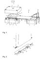
- FIG. 1 the structural design of this embodiment of the device is shown.
- the device has an injection mold with a first mold half 3 and a second mold half 4.
- the tool half 3 is arranged at the bottom in this embodiment, while the mold half 4 is arranged at the top.
- the first mold half 3 is arranged stationary on a floor, while the second mold half 4 is vertically movable relative to the first mold half 3.
- the presentation of the FIG. 1 shows the injection mold in an open position in which a conveyor 5 between the first mold half 3 and the second mold half 4 is retracted.
- the conveying device 5 is arranged on a frame 15 on which it can be moved in and out by means of a rail system 14 between the two mold halves 3 and 4.
- the conveying device 5 has to the second mold half 4 indicative of a removal element 7 for removing a finished plastic part 2 with insert 1 from the second mold half 4.
- the removal element 7 is designed as a collecting container 8. Slider / pin-like ejectors that hold the finished plastic parts 2 eject with insert 1 from the second mold half are not shown in the figures.
- the transport device 5 Towards the tool half 3, the transport device 5 in this embodiment, four storage elements 6 each for depositing an insert 2 in a corresponding cavity 11 of the first mold half 3, wherein the cavities 11 are filled during injection molding with plastic, so that the plastic part 1 with insert second arises.
- the four storage elements 6 are presently designed as gripping elements in the form of vacuum gripping elements.
- FIG. 1 now shows the conveyor 5 in the retracted state in an unloading position between the two mold halves 3 and 4.
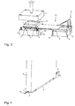
- the pointing to the tool half 3 storage elements 6 are each equipped with an insert 2, as in particular the detailed representation of FIG. 2 can be seen.
- the inserts 2, which are formed in this embodiment as needles, for example, for producing lancets are held by means of vacuum in the storage elements 6.
- FIG. 2 is clearly one of the cavities 11 to recognize, in which the insert 2 is to be inserted in the form of a needle for encapsulation with plastic.
- a shelf geometry 12 can be seen, in which the insert is stored.
- the insert 2 corresponding, not shown here surfaces, by means of which the insert is forcibly guided into its end position in the cavity can be transferred.
- FIG. 3 In the illustration according to FIG. 3 are the final products already prepared in the form of a plastic part 1 with an insert 2 already solved by the second mold half 4 and dropped into the receptacle 8.
- the storage elements 6 are now moved in the direction of the cavities 11, so that the inserts are inserted in the shelf geometry 12. In this position, the vacuum of the engagement elements 6 are reduced or canceled so that the storage elements 6 can be moved again in the direction of the transport device without them remove the inserts 2 again from the cavities 11.
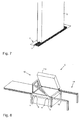
- FIG. 5 now the second mold half 4 is moved in the direction of the mold half 3, so that the injection mold is closed.
- the conveyor 5 was thereby moved from the unloading position to a loading position, in which the storage elements 6 can be fitted with new inserts 2, while the stored in the cavities 11 of the lower mold halves 3 inserts 2 in the injection mold with plastic to the finished plastic parts 1 with inserts 2 are overmoulded.
- FIG. 5 as well as the FIG. 6 to take a tilting geometry 10, which is arranged on the frame 15 and which tilts the collecting container 8 in the loading device in the loading position, so that the end products contained therein, namely plastic parts 1 with inserts 2, fall out of it and in a collection device not shown here to be collected.
- FIG. 8 shows the representation of the device according to the invention in the area of the conveyor 5 in its loading position in a view from behind. Clearly visible here is the wedge-shaped tilting geometry 10 for the collecting container 8.
- FIG. 5 the storage elements 6 of the conveyor 5 are shown in a position in which they are not yet equipped with inserts 2, but they are already positioned on magazines 9, from which they can see insert parts 2.
- FIG. 6 the storage elements 6 are now already lowered into the magazines 9, so that they can accommodate insert parts 2 by being subjected to a vacuum.
- FIG. 7 A detailed representation of a storage element 6 during the recording of an insert part 2 from a magazine 9 is in FIG. 7 shown.
- FIG. 9 now shows the storage element 6 of FIG. 7 after it has received an insert element 2 by means of vacuum.
- FIG. 11 an interior view of a storage element 6 is shown.
- the openings 3 are located in a groove 16, which serves to receive a needle-shaped insert 2, so that they are closed during transportation of the inserts by this.
- FIG. 10 shows the conveyor 5 again in a detailed representation, where clearly also the rail system 14 can be seen, on which the conveyor between the unloading and loading position is moved back and forth.
Landscapes
- Engineering & Computer Science (AREA)
- Manufacturing & Machinery (AREA)
- Mechanical Engineering (AREA)
- Robotics (AREA)
- Moulds For Moulding Plastics Or The Like (AREA)
- Injection Moulding Of Plastics Or The Like (AREA)
Applications Claiming Priority (1)
| Application Number | Priority Date | Filing Date | Title |
|---|---|---|---|
| DE102013021717.2A DE102013021717A1 (de) | 2013-12-20 | 2013-12-20 | Vorrichtung zur Herstellung von Kunststoffteilen mit Einlegeteilen in einem Spritzgießverfahren |
Publications (2)
| Publication Number | Publication Date |
|---|---|
| EP2886283A1 EP2886283A1 (de) | 2015-06-24 |
| EP2886283B1 true EP2886283B1 (de) | 2016-10-12 |
Family
ID=51987038
Family Applications (1)
| Application Number | Title | Priority Date | Filing Date |
|---|---|---|---|
| EP14194875.2A Active EP2886283B1 (de) | 2013-12-20 | 2014-11-26 | Vorrichtung zur Herstellung von Kunststoffteilen mit Einlegeteilen in einem Spritzgießverfahren |
Country Status (3)
| Country | Link |
|---|---|
| EP (1) | EP2886283B1 (pl) |
| DE (1) | DE102013021717A1 (pl) |
| PL (1) | PL2886283T3 (pl) |
Cited By (1)
| Publication number | Priority date | Publication date | Assignee | Title |
|---|---|---|---|---|
| DE202018107129U1 (de) | 2018-12-13 | 2019-01-09 | Hunold + Knoop Kunststofftechnik Gmbh | Vorrichtung zum Spritzgießen von Gießteilen |
Families Citing this family (3)
| Publication number | Priority date | Publication date | Assignee | Title |
|---|---|---|---|---|
| DE102019126939B4 (de) * | 2019-10-08 | 2022-02-10 | Lisa Dräxlmaier GmbH | Werkzeughälfte und verfahren zum herstellen eines spritzgussteils mit wenigstens einem bolzenartigen einlegeteil |
| CN213107910U (zh) * | 2020-07-02 | 2021-05-04 | 苏州金伟博精密机械科技有限公司 | 一种具备缓冲防护功能的注塑模具 |
| DE102020119681A1 (de) | 2020-07-27 | 2022-01-27 | Zahoransky Automation & Molds GmbH | Bereitstellungsvorrichtung für Kanülen, Verfahren zur Bereitstellung von Kanülen, Computerprogramm und computerlesbares Medium |
Family Cites Families (15)
| Publication number | Priority date | Publication date | Assignee | Title |
|---|---|---|---|---|
| US3358689A (en) * | 1964-06-09 | 1967-12-19 | Roehr Products Company Inc | Integral lancet and package |
| DD98636B1 (de) * | 1971-12-24 | 1974-12-20 | Vorrichtung für die Forteilentnahme an Spritzgiessmaschinen | |
| DE2428496A1 (de) * | 1973-06-15 | 1975-01-09 | Ralet | Verfahren zum verstaerken runder hohlkoerper aus gespritztem material mit hilfe eines einsatzes, sowie form zur durchfuehrung des verfahrens |
| DE3928680A1 (de) * | 1989-08-30 | 1991-03-07 | Systec Rationalisierungstechni | Einlege- und entnahmevorrichtung fuer eine weiterverarbeitende maschine |
| JP2901837B2 (ja) * | 1993-05-24 | 1999-06-07 | オムロン株式会社 | 竪型射出成形機 |
| JP2922411B2 (ja) * | 1993-12-28 | 1999-07-26 | 河西工業株式会社 | 成形品の取出し方法ならびにその取出し装置 |
| FR2727049B1 (fr) * | 1994-11-18 | 1997-01-24 | Plastic Omnium Cie | Procede de realisation d'un temoin d'usure de garniture de friction surmoule |
| AU682803B2 (en) * | 1995-12-22 | 1997-10-16 | Husky Injection Molding Systems Ltd. | Insert molding system |
| DE19803171C2 (de) * | 1998-01-28 | 2001-05-10 | Theo Hillers Gmbh | Vorrichtung zur Handhabung vorgeformter Einlegeteile und hergestellter Werkstücke einer Spritzgießmaschine |
| DE19854663A1 (de) * | 1998-11-26 | 2000-06-08 | Richard Herbst | Verfahren zum Herstellen eines mit einer Folie versehenen Kunststoff-Spritzgußteils sowie dementsprechende Spritzgießanlage |
| DE10152815C1 (de) * | 2001-10-19 | 2003-06-18 | Hekuma Gmbh | Handlinggerät für eine Kunststoff-Spritzgiessmaschine sowie Greifer für ein solches |
| US20040084809A1 (en) * | 2002-11-05 | 2004-05-06 | Vanderploeg James A. | Side shuttle apparatus and method for an injection molding machine |
| DE102005040517B4 (de) * | 2004-08-27 | 2015-11-26 | Denso Corporation | Einsatzformvorrichtung und Einsatzformverfahren |
| EP1790453A1 (de) * | 2005-11-23 | 2007-05-30 | HTP Liebscher Kunststofftechnik GmbH & Co. KG | Spritzwerkzeug zur Herstellung eines Rücklaufrohres |
| DE102011120403A1 (de) * | 2011-12-03 | 2013-06-06 | Zahoransky Ag | Vorrichtung zum Anspritzen eines Kunststoff-Formteils an ein Funktionsteil zur Bildung eines Mehrkomponeten-Teils |
-
2013
- 2013-12-20 DE DE102013021717.2A patent/DE102013021717A1/de not_active Withdrawn
-
2014
- 2014-11-26 EP EP14194875.2A patent/EP2886283B1/de active Active
- 2014-11-26 PL PL14194875T patent/PL2886283T3/pl unknown
Non-Patent Citations (1)
| Title |
|---|
| None * |
Cited By (2)
| Publication number | Priority date | Publication date | Assignee | Title |
|---|---|---|---|---|
| DE202018107129U1 (de) | 2018-12-13 | 2019-01-09 | Hunold + Knoop Kunststofftechnik Gmbh | Vorrichtung zum Spritzgießen von Gießteilen |
| DE102019130595A1 (de) | 2018-12-13 | 2020-06-18 | Hunold + Knoop Kunststofftechnik Gmbh | Vorrichtung zum Spritzgießen von Gießteilen |
Also Published As
| Publication number | Publication date |
|---|---|
| PL2886283T3 (pl) | 2017-03-31 |
| EP2886283A1 (de) | 2015-06-24 |
| DE102013021717A1 (de) | 2015-06-25 |
Similar Documents
| Publication | Publication Date | Title |
|---|---|---|
| EP2886283B1 (de) | Vorrichtung zur Herstellung von Kunststoffteilen mit Einlegeteilen in einem Spritzgießverfahren | |
| DE4426127C2 (de) | Verfahren und Vorrichtung zum Vergießen elektronischer Teile mit Gießharz | |
| DE102007007068A1 (de) | Vorrichtung und Verfahren zum Befüllen von Behältern mit stabförmigen Produkten | |
| DE102008020350A1 (de) | Blechbeförderungssystem | |
| DE102004055629A1 (de) | Vorrichtung und Verfahren zum aufeinanderfolgenden Entleeren von mit Artikeln gefüllten Behältern | |
| EP3093115B1 (de) | Aufnahmevorrichtung und anspritzverfahren | |
| EP2842541A1 (de) | Vorrichtung zum Befüllen und Verschließen von Kapseln | |
| EP3313624B1 (de) | Beschickungssystem für werkstücke | |
| DE102005026687B4 (de) | Verfahren und Vorrichtung zum Stapeln von tiefgezogenen Artikeln | |
| WO2021121977A1 (de) | WERKZEUG UND VERFAHREN ZUM SPRITZGIEßEN EINES SPRITZLINGS IN EINEM WERKZEUG | |
| DE102015112468B4 (de) | Vorrichtung und Verfahren zum Positionieren und Übergeben von Gegenständen | |
| EP1704105B1 (de) | Anordnung zum befüllen und/oder entleeren von mit artikeln gefüllten und/oder zu befüllenden behältern sowie handhabungsvorrichtung zum transportieren der behälter | |
| DE102017118527A1 (de) | Handhabungsvorrichtung für Kunststoffspritzgussteile, Spritzgussanlage sowie Betriebsverfahren | |
| EP3033207A1 (de) | Handhabungsvorrichtung zum einschieben von werkstückträgern in stapelboxen, system sowie handhabungsverfahren | |
| DE102016004532A1 (de) | Verfahren zur Handhabung von Teile aufnehmenden, gestapelten Teileträgern innerhalb einer Automationszelle und Automationszelle zur Durchführung des Verfahrens | |
| DE102015005643A1 (de) | Verfahren und Vorrichtung zum Bereitstellen von unterschiedlichen Karosseriebauteilvarianten | |
| DE112014002134T5 (de) | In-Mold-Anlagensystem für eine Spritzgussmaschine | |
| DE3725399A1 (de) | Verfahren und vorrichtung zum zumindest teilweisen umspritzen von werkstuecken | |
| DE102007000994A1 (de) | Spritzgießvorrichtung zur Herstellung von Kunststoffbauteilen aus wenigstens zwei Kunststoffkomponenten | |
| EP4186674B1 (de) | Vorrichtung zum spritzgiessen eines formteils mit einem einleger | |
| DE102018214050B4 (de) | Palettiervorrichtung und Verfahren zum Betrieb einer Palettiervorrichtung | |
| DE202008012069U1 (de) | Lagerautomat | |
| EP3717202B1 (de) | Vorrichtung zum entfernen von kunststofferzeugnissen | |
| EP1518639B1 (de) | Vorrichtung zum Abführen von Fertigungsteilen aus einem Prozessraum | |
| EP2886496B1 (de) | Vorrichtung und Verfahren zum Aufnehmen von Werkstücken |
Legal Events
| Date | Code | Title | Description |
|---|---|---|---|
| PUAI | Public reference made under article 153(3) epc to a published international application that has entered the european phase |
Free format text: ORIGINAL CODE: 0009012 |
|
| 17P | Request for examination filed |
Effective date: 20141126 |
|
| AK | Designated contracting states |
Kind code of ref document: A1 Designated state(s): AL AT BE BG CH CY CZ DE DK EE ES FI FR GB GR HR HU IE IS IT LI LT LU LV MC MK MT NL NO PL PT RO RS SE SI SK SM TR |
|
| AX | Request for extension of the european patent |
Extension state: BA ME |
|
| R17P | Request for examination filed (corrected) |
Effective date: 20150709 |
|
| RBV | Designated contracting states (corrected) |
Designated state(s): AL AT BE BG CH CY CZ DE DK EE ES FI FR GB GR HR HU IE IS IT LI LT LU LV MC MK MT NL NO PL PT RO RS SE SI SK SM TR |
|
| 17Q | First examination report despatched |
Effective date: 20150924 |
|
| GRAP | Despatch of communication of intention to grant a patent |
Free format text: ORIGINAL CODE: EPIDOSNIGR1 |
|
| INTG | Intention to grant announced |
Effective date: 20160725 |
|
| GRAS | Grant fee paid |
Free format text: ORIGINAL CODE: EPIDOSNIGR3 |
|
| GRAA | (expected) grant |
Free format text: ORIGINAL CODE: 0009210 |
|
| AK | Designated contracting states |
Kind code of ref document: B1 Designated state(s): AL AT BE BG CH CY CZ DE DK EE ES FI FR GB GR HR HU IE IS IT LI LT LU LV MC MK MT NL NO PL PT RO RS SE SI SK SM TR |
|
| REG | Reference to a national code |
Ref country code: GB Ref legal event code: FG4D Free format text: NOT ENGLISH |
|
| REG | Reference to a national code |
Ref country code: CH Ref legal event code: EP |
|
| REG | Reference to a national code |
Ref country code: AT Ref legal event code: REF Ref document number: 836086 Country of ref document: AT Kind code of ref document: T Effective date: 20161015 |
|
| REG | Reference to a national code |
Ref country code: IE Ref legal event code: FG4D Free format text: LANGUAGE OF EP DOCUMENT: GERMAN |
|
| REG | Reference to a national code |
Ref country code: DE Ref legal event code: R096 Ref document number: 502014001697 Country of ref document: DE |
|
| REG | Reference to a national code |
Ref country code: FR Ref legal event code: PLFP Year of fee payment: 3 |
|
| REG | Reference to a national code |
Ref country code: CH Ref legal event code: NV Representative=s name: ROTTMANN, ZIMMERMANN + PARTNER AG, CH |
|
| REG | Reference to a national code |
Ref country code: LT Ref legal event code: MG4D |
|
| REG | Reference to a national code |
Ref country code: NL Ref legal event code: MP Effective date: 20161012 |
|
| PG25 | Lapsed in a contracting state [announced via postgrant information from national office to epo] |
Ref country code: LV Free format text: LAPSE BECAUSE OF FAILURE TO SUBMIT A TRANSLATION OF THE DESCRIPTION OR TO PAY THE FEE WITHIN THE PRESCRIBED TIME-LIMIT Effective date: 20161012 Ref country code: BE Free format text: LAPSE BECAUSE OF NON-PAYMENT OF DUE FEES Effective date: 20161130 |
|
| PG25 | Lapsed in a contracting state [announced via postgrant information from national office to epo] |
Ref country code: SE Free format text: LAPSE BECAUSE OF FAILURE TO SUBMIT A TRANSLATION OF THE DESCRIPTION OR TO PAY THE FEE WITHIN THE PRESCRIBED TIME-LIMIT Effective date: 20161012 Ref country code: NO Free format text: LAPSE BECAUSE OF FAILURE TO SUBMIT A TRANSLATION OF THE DESCRIPTION OR TO PAY THE FEE WITHIN THE PRESCRIBED TIME-LIMIT Effective date: 20170112 Ref country code: GR Free format text: LAPSE BECAUSE OF FAILURE TO SUBMIT A TRANSLATION OF THE DESCRIPTION OR TO PAY THE FEE WITHIN THE PRESCRIBED TIME-LIMIT Effective date: 20170113 Ref country code: LT Free format text: LAPSE BECAUSE OF FAILURE TO SUBMIT A TRANSLATION OF THE DESCRIPTION OR TO PAY THE FEE WITHIN THE PRESCRIBED TIME-LIMIT Effective date: 20161012 |
|
| PG25 | Lapsed in a contracting state [announced via postgrant information from national office to epo] |
Ref country code: FI Free format text: LAPSE BECAUSE OF FAILURE TO SUBMIT A TRANSLATION OF THE DESCRIPTION OR TO PAY THE FEE WITHIN THE PRESCRIBED TIME-LIMIT Effective date: 20161012 Ref country code: RS Free format text: LAPSE BECAUSE OF FAILURE TO SUBMIT A TRANSLATION OF THE DESCRIPTION OR TO PAY THE FEE WITHIN THE PRESCRIBED TIME-LIMIT Effective date: 20161012 Ref country code: HR Free format text: LAPSE BECAUSE OF FAILURE TO SUBMIT A TRANSLATION OF THE DESCRIPTION OR TO PAY THE FEE WITHIN THE PRESCRIBED TIME-LIMIT Effective date: 20161012 Ref country code: NL Free format text: LAPSE BECAUSE OF FAILURE TO SUBMIT A TRANSLATION OF THE DESCRIPTION OR TO PAY THE FEE WITHIN THE PRESCRIBED TIME-LIMIT Effective date: 20161012 Ref country code: ES Free format text: LAPSE BECAUSE OF FAILURE TO SUBMIT A TRANSLATION OF THE DESCRIPTION OR TO PAY THE FEE WITHIN THE PRESCRIBED TIME-LIMIT Effective date: 20161012 Ref country code: PT Free format text: LAPSE BECAUSE OF FAILURE TO SUBMIT A TRANSLATION OF THE DESCRIPTION OR TO PAY THE FEE WITHIN THE PRESCRIBED TIME-LIMIT Effective date: 20170213 Ref country code: IS Free format text: LAPSE BECAUSE OF FAILURE TO SUBMIT A TRANSLATION OF THE DESCRIPTION OR TO PAY THE FEE WITHIN THE PRESCRIBED TIME-LIMIT Effective date: 20170212 |
|
| REG | Reference to a national code |
Ref country code: DE Ref legal event code: R097 Ref document number: 502014001697 Country of ref document: DE |
|
| PG25 | Lapsed in a contracting state [announced via postgrant information from national office to epo] |
Ref country code: SK Free format text: LAPSE BECAUSE OF FAILURE TO SUBMIT A TRANSLATION OF THE DESCRIPTION OR TO PAY THE FEE WITHIN THE PRESCRIBED TIME-LIMIT Effective date: 20161012 Ref country code: DK Free format text: LAPSE BECAUSE OF FAILURE TO SUBMIT A TRANSLATION OF THE DESCRIPTION OR TO PAY THE FEE WITHIN THE PRESCRIBED TIME-LIMIT Effective date: 20161012 Ref country code: EE Free format text: LAPSE BECAUSE OF FAILURE TO SUBMIT A TRANSLATION OF THE DESCRIPTION OR TO PAY THE FEE WITHIN THE PRESCRIBED TIME-LIMIT Effective date: 20161012 Ref country code: RO Free format text: LAPSE BECAUSE OF FAILURE TO SUBMIT A TRANSLATION OF THE DESCRIPTION OR TO PAY THE FEE WITHIN THE PRESCRIBED TIME-LIMIT Effective date: 20161012 Ref country code: MC Free format text: LAPSE BECAUSE OF FAILURE TO SUBMIT A TRANSLATION OF THE DESCRIPTION OR TO PAY THE FEE WITHIN THE PRESCRIBED TIME-LIMIT Effective date: 20161012 |
|
| PLBE | No opposition filed within time limit |
Free format text: ORIGINAL CODE: 0009261 |
|
| STAA | Information on the status of an ep patent application or granted ep patent |
Free format text: STATUS: NO OPPOSITION FILED WITHIN TIME LIMIT |
|
| REG | Reference to a national code |
Ref country code: IE Ref legal event code: MM4A |
|
| PG25 | Lapsed in a contracting state [announced via postgrant information from national office to epo] |
Ref country code: BG Free format text: LAPSE BECAUSE OF FAILURE TO SUBMIT A TRANSLATION OF THE DESCRIPTION OR TO PAY THE FEE WITHIN THE PRESCRIBED TIME-LIMIT Effective date: 20170112 Ref country code: IT Free format text: LAPSE BECAUSE OF FAILURE TO SUBMIT A TRANSLATION OF THE DESCRIPTION OR TO PAY THE FEE WITHIN THE PRESCRIBED TIME-LIMIT Effective date: 20161012 Ref country code: SM Free format text: LAPSE BECAUSE OF FAILURE TO SUBMIT A TRANSLATION OF THE DESCRIPTION OR TO PAY THE FEE WITHIN THE PRESCRIBED TIME-LIMIT Effective date: 20161012 |
|
| 26N | No opposition filed |
Effective date: 20170713 |
|
| PG25 | Lapsed in a contracting state [announced via postgrant information from national office to epo] |
Ref country code: LU Free format text: LAPSE BECAUSE OF NON-PAYMENT OF DUE FEES Effective date: 20161130 |
|
| REG | Reference to a national code |
Ref country code: FR Ref legal event code: PLFP Year of fee payment: 4 |
|
| PG25 | Lapsed in a contracting state [announced via postgrant information from national office to epo] |
Ref country code: SI Free format text: LAPSE BECAUSE OF FAILURE TO SUBMIT A TRANSLATION OF THE DESCRIPTION OR TO PAY THE FEE WITHIN THE PRESCRIBED TIME-LIMIT Effective date: 20161012 Ref country code: IE Free format text: LAPSE BECAUSE OF NON-PAYMENT OF DUE FEES Effective date: 20161126 |
|
| REG | Reference to a national code |
Ref country code: BE Ref legal event code: MM Effective date: 20161130 |
|
| PG25 | Lapsed in a contracting state [announced via postgrant information from national office to epo] |
Ref country code: HU Free format text: LAPSE BECAUSE OF FAILURE TO SUBMIT A TRANSLATION OF THE DESCRIPTION OR TO PAY THE FEE WITHIN THE PRESCRIBED TIME-LIMIT; INVALID AB INITIO Effective date: 20141126 |
|
| PG25 | Lapsed in a contracting state [announced via postgrant information from national office to epo] |
Ref country code: CY Free format text: LAPSE BECAUSE OF FAILURE TO SUBMIT A TRANSLATION OF THE DESCRIPTION OR TO PAY THE FEE WITHIN THE PRESCRIBED TIME-LIMIT Effective date: 20161012 Ref country code: MK Free format text: LAPSE BECAUSE OF FAILURE TO SUBMIT A TRANSLATION OF THE DESCRIPTION OR TO PAY THE FEE WITHIN THE PRESCRIBED TIME-LIMIT Effective date: 20161012 |
|
| PG25 | Lapsed in a contracting state [announced via postgrant information from national office to epo] |
Ref country code: MT Free format text: LAPSE BECAUSE OF FAILURE TO SUBMIT A TRANSLATION OF THE DESCRIPTION OR TO PAY THE FEE WITHIN THE PRESCRIBED TIME-LIMIT Effective date: 20161012 |
|
| PG25 | Lapsed in a contracting state [announced via postgrant information from national office to epo] |
Ref country code: TR Free format text: LAPSE BECAUSE OF FAILURE TO SUBMIT A TRANSLATION OF THE DESCRIPTION OR TO PAY THE FEE WITHIN THE PRESCRIBED TIME-LIMIT Effective date: 20161012 |
|
| PG25 | Lapsed in a contracting state [announced via postgrant information from national office to epo] |
Ref country code: AL Free format text: LAPSE BECAUSE OF FAILURE TO SUBMIT A TRANSLATION OF THE DESCRIPTION OR TO PAY THE FEE WITHIN THE PRESCRIBED TIME-LIMIT Effective date: 20161012 |
|
| REG | Reference to a national code |
Ref country code: AT Ref legal event code: MM01 Ref document number: 836086 Country of ref document: AT Kind code of ref document: T Effective date: 20191126 |
|
| PG25 | Lapsed in a contracting state [announced via postgrant information from national office to epo] |
Ref country code: AT Free format text: LAPSE BECAUSE OF NON-PAYMENT OF DUE FEES Effective date: 20191126 |
|
| P01 | Opt-out of the competence of the unified patent court (upc) registered |
Effective date: 20230523 |
|
| REG | Reference to a national code |
Ref country code: CH Ref legal event code: U11 Free format text: ST27 STATUS EVENT CODE: U-0-0-U10-U11 (AS PROVIDED BY THE NATIONAL OFFICE) Effective date: 20251201 |
|
| PGFP | Annual fee paid to national office [announced via postgrant information from national office to epo] |
Ref country code: DE Payment date: 20251118 Year of fee payment: 12 |
|
| PGFP | Annual fee paid to national office [announced via postgrant information from national office to epo] |
Ref country code: GB Payment date: 20251120 Year of fee payment: 12 |
|
| PGFP | Annual fee paid to national office [announced via postgrant information from national office to epo] |
Ref country code: FR Payment date: 20251120 Year of fee payment: 12 |
|
| PGFP | Annual fee paid to national office [announced via postgrant information from national office to epo] |
Ref country code: CH Payment date: 20251201 Year of fee payment: 12 |
|
| PGFP | Annual fee paid to national office [announced via postgrant information from national office to epo] |
Ref country code: CZ Payment date: 20251113 Year of fee payment: 12 |
|
| PGFP | Annual fee paid to national office [announced via postgrant information from national office to epo] |
Ref country code: PL Payment date: 20251119 Year of fee payment: 12 |