EP2883588B1 - Dispositif de séparation solide-liquide - Google Patents
Dispositif de séparation solide-liquide Download PDFInfo
- Publication number
- EP2883588B1 EP2883588B1 EP12885046.8A EP12885046A EP2883588B1 EP 2883588 B1 EP2883588 B1 EP 2883588B1 EP 12885046 A EP12885046 A EP 12885046A EP 2883588 B1 EP2883588 B1 EP 2883588B1
- Authority
- EP
- European Patent Office
- Prior art keywords
- filter
- disk filter
- diameter disk
- piece
- projection
- Prior art date
- Legal status (The legal status is an assumption and is not a legal conclusion. Google has not performed a legal analysis and makes no representation as to the accuracy of the status listed.)
- Active
Links
- 239000007788 liquid Substances 0.000 title claims description 52
- 238000000926 separation method Methods 0.000 title description 5
- 239000000706 filtrate Substances 0.000 claims description 40
- 239000007787 solid Substances 0.000 claims description 27
- 230000001174 ascending effect Effects 0.000 claims description 6
- 239000010419 fine particle Substances 0.000 claims description 5
- 239000011347 resin Substances 0.000 claims description 5
- 229920005989 resin Polymers 0.000 claims description 5
- 238000001914 filtration Methods 0.000 description 21
- 239000000725 suspension Substances 0.000 description 9
- 230000010355 oscillation Effects 0.000 description 4
- 239000000047 product Substances 0.000 description 4
- 239000010865 sewage Substances 0.000 description 4
- 238000004519 manufacturing process Methods 0.000 description 3
- 239000010802 sludge Substances 0.000 description 3
- 238000004140 cleaning Methods 0.000 description 2
- 230000000694 effects Effects 0.000 description 2
- 244000144972 livestock Species 0.000 description 2
- 238000000034 method Methods 0.000 description 2
- 238000010008 shearing Methods 0.000 description 2
- 239000002689 soil Substances 0.000 description 2
- 239000000126 substance Substances 0.000 description 2
- 239000002351 wastewater Substances 0.000 description 2
- XLYOFNOQVPJJNP-UHFFFAOYSA-N water Substances O XLYOFNOQVPJJNP-UHFFFAOYSA-N 0.000 description 2
- XRKOOHTZZDPJNE-UHFFFAOYSA-N CCCCCC(F)(F)F Chemical compound CCCCCC(F)(F)F XRKOOHTZZDPJNE-UHFFFAOYSA-N 0.000 description 1
- 230000005540 biological transmission Effects 0.000 description 1
- 230000015572 biosynthetic process Effects 0.000 description 1
- 238000005520 cutting process Methods 0.000 description 1
- 230000006378 damage Effects 0.000 description 1
- 230000007613 environmental effect Effects 0.000 description 1
- 230000002452 interceptive effect Effects 0.000 description 1
- JEIPFZHSYJVQDO-UHFFFAOYSA-N iron(III) oxide Inorganic materials O=[Fe]O[Fe]=O JEIPFZHSYJVQDO-UHFFFAOYSA-N 0.000 description 1
- 238000012986 modification Methods 0.000 description 1
- 230000004048 modification Effects 0.000 description 1
- 238000003825 pressing Methods 0.000 description 1
- 238000007789 sealing Methods 0.000 description 1
- 239000012265 solid product Substances 0.000 description 1
- 125000006850 spacer group Chemical group 0.000 description 1
- -1 that is Substances 0.000 description 1
- 238000004065 wastewater treatment Methods 0.000 description 1
Images


Classifications
-
- C—CHEMISTRY; METALLURGY
- C02—TREATMENT OF WATER, WASTE WATER, SEWAGE, OR SLUDGE
- C02F—TREATMENT OF WATER, WASTE WATER, SEWAGE, OR SLUDGE
- C02F11/00—Treatment of sludge; Devices therefor
- C02F11/12—Treatment of sludge; Devices therefor by de-watering, drying or thickening
- C02F11/121—Treatment of sludge; Devices therefor by de-watering, drying or thickening by mechanical de-watering
-
- B—PERFORMING OPERATIONS; TRANSPORTING
- B01—PHYSICAL OR CHEMICAL PROCESSES OR APPARATUS IN GENERAL
- B01D—SEPARATION
- B01D33/00—Filters with filtering elements which move during the filtering operation
- B01D33/27—Filters with filtering elements which move during the filtering operation with rotary filtering surfaces, which are neither cylindrical nor planar, e.g. helical surfaces
- B01D33/275—Filters with filtering elements which move during the filtering operation with rotary filtering surfaces, which are neither cylindrical nor planar, e.g. helical surfaces using contiguous impervious surfaces
-
- C—CHEMISTRY; METALLURGY
- C02—TREATMENT OF WATER, WASTE WATER, SEWAGE, OR SLUDGE
- C02F—TREATMENT OF WATER, WASTE WATER, SEWAGE, OR SLUDGE
- C02F2103/00—Nature of the water, waste water, sewage or sludge to be treated
- C02F2103/005—Black water originating from toilets
-
- C—CHEMISTRY; METALLURGY
- C02—TREATMENT OF WATER, WASTE WATER, SEWAGE, OR SLUDGE
- C02F—TREATMENT OF WATER, WASTE WATER, SEWAGE, OR SLUDGE
- C02F2103/00—Nature of the water, waste water, sewage or sludge to be treated
- C02F2103/20—Nature of the water, waste water, sewage or sludge to be treated from animal husbandry
-
- C—CHEMISTRY; METALLURGY
- C02—TREATMENT OF WATER, WASTE WATER, SEWAGE, OR SLUDGE
- C02F—TREATMENT OF WATER, WASTE WATER, SEWAGE, OR SLUDGE
- C02F2103/00—Nature of the water, waste water, sewage or sludge to be treated
- C02F2103/32—Nature of the water, waste water, sewage or sludge to be treated from the food or foodstuff industry, e.g. brewery waste waters
-
- C—CHEMISTRY; METALLURGY
- C02—TREATMENT OF WATER, WASTE WATER, SEWAGE, OR SLUDGE
- C02F—TREATMENT OF WATER, WASTE WATER, SEWAGE, OR SLUDGE
- C02F2203/00—Apparatus and plants for the biological treatment of water, waste water or sewage
- C02F2203/006—Apparatus and plants for the biological treatment of water, waste water or sewage details of construction, e.g. specially adapted seals, modules, connections
Definitions
- the present invention relates to a solid-liquid separator for separately taking out a solid component and a liquid component separated from the solids of sludge, in particular, the suspended solids (SS) contained in the liquid produced in, for example, a sewage plant, a night soil treatment plant, or a treatment plant for treating wastewater containing sludge in industries such as livestock and agricultural industries, food manufacturing industry, and chemical industry.
- a solid-liquid separator for separately taking out a solid component and a liquid component separated from the solids of sludge, in particular, the suspended solids (SS) contained in the liquid produced in, for example, a sewage plant, a night soil treatment plant, or a treatment plant for treating wastewater containing sludge in industries such as livestock and agricultural industries, food manufacturing industry, and chemical industry.
- wastewater containing sludge that is, sewage suspension produced in, for example, a sewage plant, a night soil treatment plant, or a wastewater treatment plant in industries such as livestock and agricultural industries, food manufacturing industry, and chemical industry, cannot be drained as it is from the viewpoint of environmental destruction.
- wastewater containing sludge that is, sewage suspension produced in, for example, a sewage plant, a night soil treatment plant, or a wastewater treatment plant in industries such as livestock and agricultural industries, food manufacturing industry, and chemical industry
- JPH 02-31807 A discloses a filtration apparatus having a plurality of layered rotary filter units arranged at regular intervals in a discharge direction, each of the layered rotary filter units having a plurality of sets of filter pieces secured to a rotary shaft inserted therethrough, each of the sets having a large-diameter filter piece, a small-diameter filter piece and a spacer filter piece that are different in diameter and each having a thickness of about 1 mm to 2 mm.
- the rotary filter units are rotated in the same direction.
- Outer circumferential edges of the large-diameter disk filter pieces of one of the mutually adjacent layered rotary filter units is disposed close to outer circumferential edges of the small-diameter disk filter pieces of the other of the layered rotary filter units.
- each of the large-diameter disk filter pieces of the layered rotary filter unit is combined with adjacent ones, in front and rear, of the small-diameter disk filter pieces such that it faces the small-diameter disk filter pieces, so that when the layered rotary filter units are rotated, the large-diameter disk filter pieces rotate through narrow gaps between the small-diameter disk filter pieces, thereby filtering suspension liquid while preventing a clogging between filtering surfaces.
- JP 2979296 B2 discloses a filtration apparatus for filtering suspension liquid, wherein large-diameter filter pieces and small-diameter filter pieces of the layered rotary filter units are different in diameter and have a thickness of about 0.2 mm to 1 mm.
- JP S53-141979 A discloses a filtration apparatus for filtering suspension liquid, wherein large-diameter filter pieces and small-diameter filter pieces of the layered rotary filter units are different in diameter and have a smaller thickness of 0.05 mm to 0.8 mm.
- the narrow gaps between the small-diameter disk filter pieces need to be at least slightly wider than the thickness of the large-diameter disk filter pieces that are rotated in a state in which they mesh with the small-diameter disk filter pieces.
- the large-diameter disk filter pieces are completely fixed to the rotary shaft, they rotate along the same track.
- the large-diameter and small-diameter disk filter pieces of the layered rotary filter unit have a smaller thickness of 0.05 mm to 0.8 mm, and in a region where the outer circumferential edges of the large-diameter disk filter pieces of one of the mutually adjacent layered rotary filter units is disposed close to the outer circumferential edges of the small-diameter disk filter pieces of the other of the layered rotary filter units, that is, in a meshing region, each gap between the large-diameter disk filter pieces of the other forms a narrow clearance groove of 0.2 mm.
- assembling is carried out while adjusting and confirming the clearance at the front and rear surfaces of each of the large-diameter disk filter pieces inserted into the respective narrow clearance grooves by inserting an adjusting member, such as an adjusting film having a thickness of about 0.05 mm, as means for adjusting the strain of the large-diameter and small-diameter disk filter pieces or an error in the thickness thereof.
- an adjusting member such as an adjusting film having a thickness of about 0.05 mm
- the solid-liquid separator according to the present invention further comprise a double layered rotary filter unit including a pair of projection-equipped disk filter pieces, a small-diameter disk filter piece, and a rotary shaft, wherein an end face of the projection of one of the pair of projection-equipped disk filter pieces of the double layered rotary filter units abuts a back surface of the other projection-equipped disk filter piece in series to form a plurality of third filter grooves, the small-diameter disk filter piece of the double layered rotary filter unit is disposed in the third filter grooves and is stacked on an outer periphery of the rotary shaft of the double layered rotary filter unit inserted therethrough, so as to be movable in the axial direction, the double layered rotary filter unit is arranged at the end of each of the two upper and lower rows of the triple layered rotary filter units opposed to each other and/or at the beginning of the lower row on the untreated liquid inlet side, and the outer edges of the seal members are disposed
- solid-liquid separator according to the present invention be configured such that:
- the projection-equipped disk filter pieces are preferably made of resin.
- the large-diameter and small-diameter disk filter pieces are not stacked in a fixed manner in the triple layered rotary filter units, so that they can rotate while oscillating in the axial direction in the filter grooves.
- This provides oscillation actions of the small-diameter disk filter piece and the large-diameter disk filter piece in the area in the respective filter grooves wider than the thickness of the large-diameter and small-diameter disk filter pieces, that is, between the end faces of the projection-equipped disk filter pieces, an oscillation action of the large-diameter disk filter piece of the other triple layered rotary filter unit inserted into the filter groove, and in addition, a shearing action produced by the respective rotations of the outer circumferential edge of the large-diameter disk filter piece of one of the triple layered rotary filter units and the outer circumferential edge of the small-diameter disk filter piece of the other of the triple layered rotary filter units facing this large-diameter disk filter piece, thereby preventing the cake, a product of dewatering filtration that is supposed to be scraped out, from sticking and consolidating in the narrow gaps of the filter grooves.
- This self-cleaning effect is advantageous in that it can always prevent the filtering
- the filter grooves are formed by stacking the large-diameter and small-diameter disk filter pieces in a fixed manner. Therefore, the accuracy of the width and position of the filter grooves is greatly affected by the accuracy of the thickness and flatness of the filter pieces, the fastening strengths at the time of stacking and assembling, and the like. Thus, meticulous care and adjustment are required at the time of assembling, and the assembling requires great effort and skill.
- the large-diameter and small-diameter disk filter pieces are disposed in the respective filter grooves, which are formed by the abutment of the end faces of the projections of the projection-equipped disk filter pieces, such that they are movable in the axial direction. That is, they are mounted in a loosely fitted manner.
- accuracy of the filter grooves required with respect to the strain and variations (errors) in the thickness of the respective filter pieces is ensured very easily, without paying meticulous care and adjustment at the time of assembling.
- a layered rotary filter unit having a large width to enhance the treatment performance there is a great advantage that even an unskilled person can assemble it quickly and accurately.
- a solid-liquid separator according to embodiments of the present invention includes a treatment tank having an untreated liquid inlet, a solid outlet, and a filtrate outlet, a plurality of triple layered rotary filter units provided between the untreated liquid inlet and the solid outlet, each of the triple layered rotary filter units including a large-diameter disk filter piece, a small-diameter disk filter piece having a smaller diameter than the large-diameter disk filter piece, a plurality of projection-equipped disk filter pieces each having a smaller diameter than the large-diameter disk filter piece but larger than the small-diameter disk filter piece, and a rotary shaft, and seal members provided on a feed side lateral wall and a discharge side lateral wall of the treatment tank to collect fine particles contained in the liquid being treated.
- the large-diameter disk filter piece is disposed in a first filter groove of the plurality of filter grooves and is stacked on an outer periphery of the rotary shaft inserted therethrough, such that the large-diameter disk filter piece is movable in an axial direction.
- the small-diameter disk filter piece is disposed in a second filter groove next to the first filter groove and is stacked on the outer periphery of the rotary shaft inserted therethrough, such that the small-diameter disk filter piece is movable in the axial direction.
- the triple layered rotary filter units are arranged at regular intervals in an ascending manner in a discharge direction towards the solid outlet and in two upper and lower rows opposed to each other.
- an outer circumferential edge of the large-diameter disk filter piece of one of the triple layered rotary filter units is inserted into the second filter groove of the other of the triple layered rotary filter units so as to be close to the projection of the projection-equipped disk filter piece and an outer circumferential edge of the small-diameter disk filter piece of the other triple layered rotary filter unit.
- Outer edges of the seal members are disposed to face closely, with a clearance, to the outer circumferential edge of the projection-equipped disk filter piece of the triple layered rotary filter unit at an end of each of the two upper and lower rows on the solid outlet side and to the outer circumferential edge of the projection-equipped disk filter piece of the triple layered rotary filter unit at the beginning of the lower row on the untreated liquid inlet side, among the triple layered rotary filter units arranged in the two upper and lower rows opposed to each other.
- the large-diameter disk filter piece and the small-diameter disk filter piece are configured to rotate synchronously with the rotary shaft while oscillating in the axial direction in the first filter groove and the second filter groove respectively.
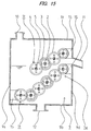
- an upper portion of a treatment tank 9 is provided with an untreated liquid inlet 10 from which untreated liquid is fed, and a lower portion of the treatment tank 9 is provided with a filtrate outlet 12 from which the filtrate after the solid-liquid separation is discharged outside the treatment tank 9.
- a lateral side portion of the treatment tank 9 is provided with a solid outlet 11 from which a cake, a solid product of dewatering filtration after the solid-liquid separation, is discharged outside the treatment tank 9.
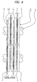
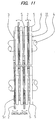
- triple layered rotary filter units It are arranged at regular intervals in ascending manner in a discharge direction towards the solid outlet 11 and in two upper and lower rows opposed to each other.
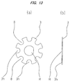
- each of the triple layered rotary filter units It includes a large-diameter disk filter piece 2, a small-diameter disk filter piece 3 having a smaller diameter than the large-diameter disk filter piece 2, a rotary shaft 4, and a plurality of projection-equipped disk filter pieces 5 each having a smaller diameter than the large-diameter disk filter piece 2 but larger than the small-diameter disk filter piece 3.
- the rotary shaft 4 has an engaging function provided by a D cut, which is obtained by cutting a portion of a cylinder to be a flat surface, or by a key (not shown). As shown in Fig.
- the rotary shaft 4 is pivotally supported by bearings 17 disposed on outer sides of the front side lateral wall 9f and the rear lateral wall 9r of the treatment tank 9, and is rotated by a drive transmission member 16 (e.g., a worm gear) provided on the outer side the front lateral wall 9f.
- a drive transmission member 16 e.g., a worm gear
- a shaft hole that fits the engaging configuration of the rotary shaft 4 is provided so as to rotate synchronously with the rotary shaft 4.
- the plurality of projection-equipped disk filter pieces 5 is provided with projections 5t, and forms filter grooves S (first and second filter grooves) by arranging the end faces of the projections 5t to abut the back surface of the adjacent one of the projection-equipped disk filter pieces 5 in series.
- the large-diameter disk filter piece 2 and the small-diameter disk filter piece 3 are disposed alternately such that they are movable in the axial direction. In this manner, the large-diameter disk filter piece 2 and the small-diameter disk filter piece 3 are configured such that they can rotate synchronously with the rotary shaft 4 while oscillating in the axial direction in the respective filter grooves S.
- the first projection-equipped disk filter piece 5 is attached to the outer periphery of the rotary shaft 4 by being inserted from the back surface opposite to the side where the projections 5t are provided, (ii) next, the large-diameter disk filter piece 2 is attached to the rotary shaft 4 by being inserted such that the projection loose engaging holes 2h of the large-diameter disk filter piece 2 engage with the projections 5t of the first projection-equipped disk filter piece 5, (iii) next, the second projection-equipped disk filter piece 5, different from the first projection-equipped disk filter piece 5, is attached by being inserted from the back surface opposite to the side where the projections 5t are provided, and the back surface of the second projection-equipped disk filter piece 5 is butted against the end faces of the projections 5t of the first projection-equipped disk filter piece
- the plurality of triple layered rotary filter units It formed by repeating the steps (i) to (v) described above are configured such that, as shown in Fig. 4 , with regard to adjacent ones of the triple layered rotary filter units It, the outer circumferential edge of the large-diameter disk filter piece 2 of one of the triple layered rotary filter units It enters the second filter groove S of the other of the triple layered rotary filter units 1t, and is disposed close to the projection 5t portion of the projection-equipped disk filter piece 5 and the outer circumferential edge of the small-diameter disk filter piece 3 of the other triple layered rotary filter unit 1t.
- seal members 15 are provided on the feed side lateral wall 9s and on the discharge side lateral wall 9d of the treatment tank 9.
- the relevant outer edges of the seal members 15 are disposed to face closely, with a slight clearance, to the outer circumferential edges of the projection-equipped disk filter pieces 5 of the triple layered rotary filter units It provided at an end of each of the two upper and low rows on the solid outlet 11 side and at the beginning of the lower row on the untreated liquid inlet 10 side.
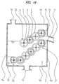
- Embodiment 2 will be described using Figs. 15 to 17 as examples.
- the treatment tank 9 is provided with a double layered rotary filter unit 1w having a pair of projection-equipped disk filter pieces 5, 5, a small-diameter disk filter piece 3, and a rotary shaft 4.
- the double layered rotary filter unit 1w is provided at the end of each of the upper and lower rows on the solid outlet 11 side and/or at the beginning of the lower row on the untreated liquid inlet 10 side.
- a method of assembling the double layered rotary filter unit 1w will be described below.
- one of the paired projection-equipped disk filter pieces 5, 5 is attached to the outer periphery of the rotary shaft 4 by being inserted from the back surface opposite to the side where the projections 5t are provided
- the small-diameter disk filter piece 3 is attached to the rotary shaft 4 by being inserted such that the projections 5t of the projection-equipped disk filter piece 5 engage with the projection cutout holes 3h of the small-diameter disk filter piece 3 and such that the small-diameter disk filter piece 3 is movable in the axial direction
- the back surface of the other projection-equipped disk filter piece 5 is butted against the end face of the projections of the previously described projection-equipped disk filter piece 5 to form a filter groove S (a third filter groove).
- the outer edges of the seal members 15 provided on the side walls of the treatment tank 9 are disposed to face closely to, with a slight clearance, the outer circumferential edges of the double layered rotary filter units 1 w formed by repeating the steps (vi) to (viii) described above. It is advantageous to form the leading end of the outer edges of the seal members 15 as a spatula-like edge having small sliding resistance like a scraper.
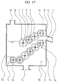
- Embodiment 3 will be described using Figs. 8 to 14 as examples.
- filtrate holes 7 are concentrically provided in the projection-equipped disk filter piece 5 and in the large-diameter disk filter piece 2
- filtrate cutout holes 8 are concentrically provided in the small-diameter disk filter piece 3.
- the filtrate holes 7 and the filtrate cutout holes 8 form filtrate passages 6 inside the respective layered rotary filter units It, 1w after being stacked.
- the opening at the filtrate sending terminal of the passage 6 leads to an inside of a filtrate chamber 13 provided outside the rear lateral wall 9r of the treatment tank 9, and a filtrate chamber outlet 14 is formed at the lower wall of the filtrate chamber 13.
- the projection-equipped disk filter pieces 5 forming the triple layered rotary filter unit It and the double layered rotary filter unit 1w are configured as resin molded pieces, which are free from rust, light in weight, not requiring processing, and suitable for mass production.
- the large-diameter disk filter piece 2 and small-diameter disk filter piece 3 are not stacked in a fixed manner in the triple layered rotary filter unit It, so that the large-diameter disk filter piece 2 and small-diameter disk filter piece 3 can rotate while oscillating in the axial direction in the respective filter grooves S.
- This provides the oscillation actions of the large-diameter disk filter piece 2 and small-diameter disk filter piece 3 in the area in the respective filter grooves S wider than the thickness of the large-diameter disk filter piece 2 and small-diameter disk filter piece 3, that is, between the end faces of the projection-equipped disk filter pieces 5, the oscillation action of the large-diameter disk filter piece 2 of the other triple layered rotary filter unit 1t inserted into the filter groove S, and in addition, a shearing action produced by the respective rotations of the outer circumferential edge of the large-diameter disk filter piece 2 and the outer circumferential edge of small-diameter disk filter piece 3 of the other triple layered rotary filter unit 1t disposed to face this large-diameter disk filter piece 2, thereby preventing the product of dewatering filtration (the cake) that is supposed to be scraped out, from sticking and consolidating in the narrow gaps of the filter grooves S. Due to this so-called self-cleaning effect that prevents
- the filter grooves are formed by stacking the large-diameter and small-diameter disk filter pieces in a fixed manner. Therefore, the accuracy of the width and position of the filter grooves is greatly affected by the accuracy of the thickness and flatness of the filter pieces, the fastening strengths at the time of stacking and assembling, and the like. Thus, meticulous care and adjustment are required at the time of assembling, and the assembling requires great effort and skill.
- the large-diameter disk filter piece 2 and the small-diameter disk filter piece 3 are disposed in the respective filter grooves S, which is formed by the abutment of the end faces of the projections of the projection-equipped disk filter pieces 5, such that they are movable in the axial direction, that is, they are mounted in a loose fit manner.
- accuracy of the filter grooves S required with respect to the strain and variations (errors) in the thickness of each of the large-diameter disk filter piece 2 and the small-diameter disk filter piece 3 is ensured very easily, without paying meticulous care and adjustment at the time of assembling.
- the seal members 15 provided on the lateral walls of the treatment tank 9 can be configured such that they are disposed to face closely to, with a slight clearance, the outer circumferential edges of the triple layered rotary filter units It or the double layered rotary filter units 1w, it is not necessary to consider the outer edges of the seal members 15 interfering with the large-diameter disk filter pieces 2.
- This configuration is excellent in the assembling efficiency, and allows the closely opposed outer edges of the seal members 15 to be formed long in the axial direction. Therefore, fine particles contained in the liquid being treated can be collected efficiently without leakage.
- the projection-equipped disk filter piece 5 which is the heaviest piece in the layered rotary filter units 1t, 1w, is made of resin, the weight of the layered rotary filter units 1t, 1w can be greatly reduced. This can reduce the drive power, can maintain the formation of the clog-free and clean filter grooves S due to being rustless, and also can produce the layered rotary filter units It, 1w as resin molded product.
- the projection-equipped disk filter pieces 5 of high dimension accuracy can be mass produced without processing, are inexpensive and are easy to assemble.
- the layered rotary filter units It, 1w can be assembled easily with high accuracy, a stable filtration function can be provided.
Landscapes
- Engineering & Computer Science (AREA)
- Chemical & Material Sciences (AREA)
- Environmental & Geological Engineering (AREA)
- Mechanical Engineering (AREA)
- Life Sciences & Earth Sciences (AREA)
- Hydrology & Water Resources (AREA)
- Water Supply & Treatment (AREA)
- Organic Chemistry (AREA)
- Chemical Kinetics & Catalysis (AREA)
- Filtration Of Liquid (AREA)
- Centrifugal Separators (AREA)
- Treatment Of Sludge (AREA)
- Biological Treatment Of Waste Water (AREA)
- Filtering Materials (AREA)
Claims (4)
- Séparateur de solide - liquide comprenant :un réservoir de traitement (9) ayant une entrée de liquide non traité (10), une sortie de solide (11), et une sortie de filtrat (12) ;une pluralité d'unités de filtre rotatives à trois couches (1t) prévues entre l'entrée de liquide non traité (10) et la sortie de solide (11), chacune des unités de filtre rotatives à trois couches (1t) comprenant une pièce de filtre à disque de grand diamètre (2), une pièce de filtre à disque de petit diamètre (3) ayant un plus petit diamètre que la pièce de filtre à disque de grand diamètre (2), une pluralité de pièces de filtre à disque équipées de saillie (5) chacune ayant un plus petit diamètre que la pièce de filtre à disque de grand diamètre (2) mais plus grand que la pièce de filtre à disque de petit diamètre (3) et un arbre rotatif (4) ; etdes éléments d'étanchéité (15) prévus sur une paroi latérale du côté de l'alimentation (9s) et une paroi latérale du côté de la décharge (9d) du réservoir de traitement (9) pour collecter de fines particules contenues dans le liquide qui est traité,dans lequel chaque pièce de filtre à disque équipée de saillie (5) a une pluralité de saillies (5t),dans lequel une face d'extrémité des saillies (5t) de chacune des pièces de filtre à disque équipées de saillie (5) vient en butée contre une surface arrière d'une pièce adjacente des pièces de filtre à disque équipées de saillie (5) en série pour former une pluralité de rainures de filtre (S),la pièce de filtre à disque de grand diamètre (2) est disposée dans une première rainure de filtre de la pluralité de rainures de filtre (S) et est empilée sur une périphérie externe de l'arbre rotatif (4) inséré à travers, de sorte que la pièce de filtre à disque de grand diamètre (2) est mobile dans une direction axiale,la pièce de filtre à disque de petit diamètre (3) est disposée dans une deuxième rainure de filtre à côté de la première rainure de filtre et est empilée sur la périphérie externe de l'arbre rotatif (4) inséré à travers, de sorte que la pièce de filtre à disque de petit diamètre (3) est mobile dans la direction axiale,les unités de filtre rotatives à trois couches (1t) sont agencées à intervalles réguliers d'une manière ascendante dans une direction de décharge vers la sortie de solide (11) et dans deux rangées supérieure et inférieure opposées entre elles,en ce qui concerne les unités adjacentes des unités de filtre rotatives à trois couches (1t), un bord circonférentiel externe de la pièce de filtre à disque de grand diamètre (2) de l'une des unités de filtre rotatives à trois couches (1t) est inséré dans la deuxième rainure de filtre de l'autre des unités de filtre rotatives à trois couches (1t) afin d'être proche des saillies (5t) de la pièce de filtre à disque équipée de saillie (5) et un bord circonférentiel externe de la pièce de filtre à disque de petit diamètre (3) de l'autre unité de filtre rotative à trois couches (1t),les bords externes des éléments d'étanchéité (15) sont disposés pour faire étroitement face, avec un jeu, au bord circonférentiel externe de la pièce de filtre à disque équipée de saillie (5) de l'unité de filtre rotative à trois couches (1t) à la fin de chacune des deux rangées supérieure et inférieure du côté de la sortie de solide et au bord circonférentiel externe de la pièce de filtre à disque équipée de saillie (5) de l'unité de filtre rotative à trois couches (1t) au début de la rangée inférieure du côté de l'entrée de liquide non traité, parmi les unités de filtre rotatives à trois couches (1t) agencées dans les deux rangées supérieure et inférieure opposées entre elles, etla pièce de filtre à disque de grand diamètre (2) et la pièce de filtre à disque de petit diamètre (3) sont configurées pour tourner de manière synchrone avec l'arbre rotatif (4) tout en oscillant dans la direction axiale dans la première rainure de filtre et la deuxième rainure de filtre, respectivement.
- Séparateur de solide - liquide selon la revendication 1, comprenant en outre une unité de filtre rotative à deux couches (1w) comprenant une paire de pièces de filtre à disque équipées de saillie (5), une pièce de filtre à disque de petit diamètre (3) et un arbre rotatif (4), dans lequel :une face d'extrémité des saillies (5t) de l'une de la paire de pièces de filtre à disque équipées de saillie (5) des unités de filtre rotatives à deux couches (1w) vient en butée contre une surface arrière de l'autre pièce de filtre à disque équipée de saillie (5) en série pour former une pluralité de troisièmes rainures de filtre (S),la pièce de filtre à disque de petit diamètre (3) de l'unité de filtre rotative à deux couches (1w) est disposée dans les troisièmes rainures de filtre (S) et est empilée sur une périphérie externe de l' arbre rotatif (4) de l'unité de filtre rotative à deux couches (1w) inséré à travers, afin d'être mobile dans la direction axiale,l'unité de filtre rotative à deux couches (1w) est agencée à la fin de chacune des deux rangées supérieure et inférieure des unités de filtre rotatives à trois couches (1t) opposées entre elles et/ou au début de la rangée inférieure du côté de l'entrée de liquide non traité, etles bords externes des éléments d'étanchéité (15) sont disposés pour faire étroitement face, avec un jeu, à un bord circonférentiel externe de l'unité de filtre rotative à deux couches (1w).
- Séparateur de liquide - solide selon la revendication 1 ou 2, dans lequel:des trous de filtrat (7) sont prévus de manière concentrique dans les pièces de filtre à disque équipées de saillie (5) et les pièces de filtre à disque de grand diamètre (2) de la pluralité d'unités de filtre rotatives à trois couches (1t) et dans les pièces de filtre à disque équipées de saillie (5) de l'unité de filtre rotative à deux couches (1w) agencées au début de la rangée inférieure du côté de l'entrée de liquide non traité, et des trous découpés de filtrat (8) sont prévus de manière concentrique dans les pièces de filtre à disque de petit diamètre (3) de la pluralité d'unités de filtre rotatives à trois couches (1t) et dans les pièces de filtre à disque de petit diamètre (3) de l'unité de filtre rotative à deux couches (1w),les trous de filtrat (7) et les trous découpés de filtrat (8) forment des passages de filtrat (6) à l'intérieur des unités de filtre rotatives à trois couches (1t) et de l'unité de filtre rotative à deux couches (1w) après avoir été empilées,des ouvertures au niveau des terminaisons d'envoi de filtre des passages de filtrat (6) respectifs conduisent dans un intérieur d'une chambre de filtrat (13) prévue à l'extérieur d'une paroi latérale arrière (9r) du réservoir de traitement (9), etune paroi inférieure de la chambre de filtrat (13) est prévue avec une sortie de chambre de filtrat (14).
- Séparateur de solide - liquide selon l'une quelconque des revendications 1 à 3, dans lequel les pièces de filtre à disque équipées de saillie (5) sont réalisées à partir de résine.
Priority Applications (3)
| Application Number | Priority Date | Filing Date | Title |
|---|---|---|---|
| RS20160662A RS55015B1 (sr) | 2012-09-19 | 2012-12-10 | Uređaj za razdvajanje čvrstih materija-tečnosti |
| SI201230666A SI2883588T1 (sl) | 2012-09-19 | 2012-12-10 | Ločevalna naprava trdne snovi in kapljevine |
| HRP20161070TT HRP20161070T1 (hr) | 2012-09-19 | 2016-08-23 | Uređaj za odvajanje krute tvari od tekuće tvari |
Applications Claiming Priority (2)
| Application Number | Priority Date | Filing Date | Title |
|---|---|---|---|
| JP2012205180A JP5854958B2 (ja) | 2012-09-19 | 2012-09-19 | 固液分離装置 |
| PCT/JP2012/081937 WO2014045467A1 (fr) | 2012-09-19 | 2012-12-10 | Dispositif de séparation solide-liquide |
Publications (3)
| Publication Number | Publication Date |
|---|---|
| EP2883588A1 EP2883588A1 (fr) | 2015-06-17 |
| EP2883588A4 EP2883588A4 (fr) | 2015-09-23 |
| EP2883588B1 true EP2883588B1 (fr) | 2016-05-25 |
Family
ID=50340811
Family Applications (1)
| Application Number | Title | Priority Date | Filing Date |
|---|---|---|---|
| EP12885046.8A Active EP2883588B1 (fr) | 2012-09-19 | 2012-12-10 | Dispositif de séparation solide-liquide |
Country Status (18)
| Country | Link |
|---|---|
| EP (1) | EP2883588B1 (fr) |
| JP (1) | JP5854958B2 (fr) |
| KR (1) | KR101552972B1 (fr) |
| CN (1) | CN103826716B (fr) |
| HK (1) | HK1194025A1 (fr) |
| HR (1) | HRP20161070T1 (fr) |
| HU (1) | HUE028364T2 (fr) |
| IN (1) | IN2014DN10487A (fr) |
| MY (1) | MY155737A (fr) |
| PL (1) | PL2883588T3 (fr) |
| RS (1) | RS55015B1 (fr) |
| RU (1) | RU2534769C2 (fr) |
| SG (1) | SG11201407045XA (fr) |
| SI (1) | SI2883588T1 (fr) |
| TW (1) | TWI565510B (fr) |
| UA (1) | UA106552C2 (fr) |
| WO (1) | WO2014045467A1 (fr) |
| ZA (1) | ZA201500029B (fr) |
Families Citing this family (11)
| Publication number | Priority date | Publication date | Assignee | Title |
|---|---|---|---|---|
| JP6000049B2 (ja) * | 2012-10-10 | 2016-09-28 | 株式会社鶴見製作所 | 固液分離装置 |
| JP6021655B2 (ja) * | 2013-01-23 | 2016-11-09 | 株式会社鶴見製作所 | 固液分離装置およびその制御方法 |
| JP6208041B2 (ja) * | 2014-02-25 | 2017-10-04 | 株式会社鶴見製作所 | 固液分離装置 |
| JP6169528B2 (ja) * | 2014-05-01 | 2017-07-26 | 株式会社鶴見製作所 | 固液分離装置 |
| CN104984583B (zh) * | 2015-07-28 | 2018-01-09 | 上海艾澜达泵业有限公司 | 一种用于油水分离器的餐饮垃圾固液分离设备 |
| JP6498139B2 (ja) * | 2016-03-09 | 2019-04-10 | 株式会社鶴見製作所 | 固液分離装置および固液分離システム |
| WO2018042647A1 (fr) * | 2016-09-05 | 2018-03-08 | 株式会社研電社 | Dispositif de séparation |
| CN107596786A (zh) * | 2017-08-30 | 2018-01-19 | 宁波帅康热水器有限公司 | 过滤片、热水器主体、花洒组件、安全阀和热水器 |
| JP7063099B2 (ja) * | 2018-05-10 | 2022-05-09 | 株式会社鶴見製作所 | 固液分離装置および固液分離装置の組立方法 |
| JP7120117B2 (ja) * | 2019-03-28 | 2022-08-17 | 株式会社鶴見製作所 | 多重円板型脱水機 |
| CN114573208B (zh) * | 2022-03-16 | 2023-07-14 | 重庆昆顶环保科技有限公司 | 一种用于污水处理的污泥脱水装置 |
Family Cites Families (13)
| Publication number | Priority date | Publication date | Assignee | Title |
|---|---|---|---|---|
| JPS53141979A (en) | 1977-05-17 | 1978-12-11 | Kurita Water Ind Ltd | Sludge treatmet apparatus |
| JPH0729006B2 (ja) * | 1986-06-24 | 1995-04-05 | 株式会社鶴見製作所 | 固液分離装置 |
| JPH0231807A (ja) | 1988-07-21 | 1990-02-01 | Teera Bunri:Kk | 回転ろ体間隙溝内のケーク固形化防止機能を有する連続ろ過装置 |
| JP3734557B2 (ja) * | 1996-02-07 | 2006-01-11 | 株式会社鶴見製作所 | 固液分離装置 |
| JPH1080608A (ja) * | 1996-09-09 | 1998-03-31 | Ito Seisakusho:Kk | 固液分離ドラム機におけるドラム目詰まり除去装置 |
| JP2979296B2 (ja) | 1996-09-25 | 1999-11-15 | 株式会社テエラ分離 | 懸濁液の連続式濾過装置 |
| AU763047B2 (en) * | 1998-12-02 | 2003-07-10 | Toyokazu Katabe | Screw drum type filtration device |
| JP4501220B2 (ja) * | 2000-05-12 | 2010-07-14 | 栗田工業株式会社 | 多重円板型汚泥脱水装置 |
| EP1992448B1 (fr) * | 2006-02-23 | 2011-04-13 | Bunri Incorporation | Appareil de filtration |
| JP4600343B2 (ja) * | 2006-04-24 | 2010-12-15 | 株式会社Ihi | 多重円板脱水装置 |
| RU2425710C1 (ru) * | 2010-03-11 | 2011-08-10 | Борис Лазаревич Красный | Установка для получения отфильтрованного осадка из суспензии |
| JP5021051B2 (ja) * | 2010-04-01 | 2012-09-05 | ショウワ洗浄機株式会社 | 濾過システム |
| CN201862312U (zh) * | 2010-11-25 | 2011-06-15 | 杭州大立过滤设备有限公司 | 一种新型膜堆滤芯 |
-
2012
- 2012-09-19 JP JP2012205180A patent/JP5854958B2/ja active Active
- 2012-12-10 UA UAA201303859A patent/UA106552C2/uk unknown
- 2012-12-10 SG SG11201407045XA patent/SG11201407045XA/en unknown
- 2012-12-10 SI SI201230666A patent/SI2883588T1/sl unknown
- 2012-12-10 CN CN201280003169.1A patent/CN103826716B/zh active Active
- 2012-12-10 HU HUE12885046A patent/HUE028364T2/en unknown
- 2012-12-10 EP EP12885046.8A patent/EP2883588B1/fr active Active
- 2012-12-10 RU RU2013113945/05A patent/RU2534769C2/ru active
- 2012-12-10 MY MYPI2014703915A patent/MY155737A/en unknown
- 2012-12-10 WO PCT/JP2012/081937 patent/WO2014045467A1/fr active Application Filing
- 2012-12-10 KR KR1020147034918A patent/KR101552972B1/ko active IP Right Grant
- 2012-12-10 IN IN10487DEN2014 patent/IN2014DN10487A/en unknown
- 2012-12-10 RS RS20160662A patent/RS55015B1/sr unknown
- 2012-12-10 PL PL12885046.8T patent/PL2883588T3/pl unknown
-
2013
- 2013-01-21 TW TW102102232A patent/TWI565510B/zh active
-
2014
- 2014-07-24 HK HK14107552.9A patent/HK1194025A1/zh unknown
-
2015
- 2015-01-06 ZA ZA2015/00029A patent/ZA201500029B/en unknown
-
2016
- 2016-08-23 HR HRP20161070TT patent/HRP20161070T1/hr unknown
Also Published As
| Publication number | Publication date |
|---|---|
| SI2883588T1 (sl) | 2016-09-30 |
| WO2014045467A1 (fr) | 2014-03-27 |
| CN103826716B (zh) | 2015-11-25 |
| HK1194025A1 (zh) | 2014-10-10 |
| TWI565510B (zh) | 2017-01-11 |
| MY155737A (en) | 2015-11-17 |
| ZA201500029B (en) | 2016-10-26 |
| JP2014057928A (ja) | 2014-04-03 |
| JP5854958B2 (ja) | 2016-02-09 |
| KR20150004434A (ko) | 2015-01-12 |
| HRP20161070T1 (hr) | 2016-10-21 |
| RU2534769C2 (ru) | 2014-12-10 |
| KR101552972B1 (ko) | 2015-09-14 |
| RU2013113945A (ru) | 2014-10-10 |
| CN103826716A (zh) | 2014-05-28 |
| EP2883588A4 (fr) | 2015-09-23 |
| IN2014DN10487A (fr) | 2015-08-21 |
| SG11201407045XA (en) | 2014-12-30 |
| AU2012390427A1 (en) | 2014-12-18 |
| EP2883588A1 (fr) | 2015-06-17 |
| PL2883588T3 (pl) | 2016-12-30 |
| UA106552C2 (uk) | 2014-09-10 |
| TW201412373A (zh) | 2014-04-01 |
| RS55015B1 (sr) | 2016-11-30 |
| HUE028364T2 (en) | 2016-12-28 |
Similar Documents
| Publication | Publication Date | Title |
|---|---|---|
| EP2883588B1 (fr) | Dispositif de séparation solide-liquide | |
| CA2800732C (fr) | Dispositif de separation solide-liquide | |
| US10786763B2 (en) | Filter for extruder press | |
| AU2007252688A1 (en) | Solid-liquid separation apparatus | |
| ZA200300268B (en) | Filter. | |
| JP4570539B2 (ja) | スクリュー式濾過脱水装置 | |
| US20150343350A1 (en) | Split filter block for extruder press | |
| AU2015263760A1 (en) | Solid/fluid separation device and method | |
| CN109383066B (zh) | 固液分离装置 | |
| JP6208041B2 (ja) | 固液分離装置 | |
| CN104416939B (zh) | 螺旋挤压式脱水装置 | |
| KR101760674B1 (ko) | 세라믹 분리막 모듈 및 이를 구비한 여과농축장치 | |
| JP6401356B2 (ja) | 固液分離装置 | |
| KR100811848B1 (ko) | 여과장치의 배럴 형성용 유니트링, 및 이를 채용한여과장치 | |
| JP6000049B2 (ja) | 固液分離装置 | |
| JP2007289839A (ja) | 多重円板脱水装置 | |
| KR101602769B1 (ko) | 다중 원판 고액 분리 장치 | |
| JP2007105586A (ja) | ろ過装置 | |
| JP2002126799A (ja) | 濾過槽を積載した移動式脱水車 | |
| JPH03232507A (ja) | スペーサ付濾片 | |
| JP2004160323A (ja) | スクリュー式濾過脱水装置 | |
| JP2004337754A (ja) | スクリュー式濾過脱水装置 | |
| CN113209680A (zh) | 过滤组件及其构成的浓缩过滤机 | |
| JP2003245797A (ja) | スクリュー式濾過脱水装置 | |
| JPS61129013A (ja) | スリツトロ−ラ式脱水装置 |
Legal Events
| Date | Code | Title | Description |
|---|---|---|---|
| PUAI | Public reference made under article 153(3) epc to a published international application that has entered the european phase |
Free format text: ORIGINAL CODE: 0009012 |
|
| 17P | Request for examination filed |
Effective date: 20141128 |
|
| AK | Designated contracting states |
Kind code of ref document: A1 Designated state(s): AL AT BE BG CH CY CZ DE DK EE ES FI FR GB GR HR HU IE IS IT LI LT LU LV MC MK MT NL NO PL PT RO RS SE SI SK SM TR |
|
| AX | Request for extension of the european patent |
Extension state: BA ME |
|
| RA4 | Supplementary search report drawn up and despatched (corrected) |
Effective date: 20150826 |
|
| RIC1 | Information provided on ipc code assigned before grant |
Ipc: B01D 33/00 20060101ALI20150820BHEP Ipc: C02F 103/32 20060101ALN20150820BHEP Ipc: C02F 103/20 20060101ALN20150820BHEP Ipc: B01D 33/27 20060101ALI20150820BHEP Ipc: C02F 103/00 20060101ALN20150820BHEP Ipc: C02F 11/12 20060101AFI20150820BHEP |
|
| REG | Reference to a national code |
Ref country code: DE Ref legal event code: R079 Ref document number: 602012019091 Country of ref document: DE Free format text: PREVIOUS MAIN CLASS: B01D0033000000 Ipc: C02F0011120000 |
|
| GRAP | Despatch of communication of intention to grant a patent |
Free format text: ORIGINAL CODE: EPIDOSNIGR1 |
|
| DAX | Request for extension of the european patent (deleted) | ||
| RIC1 | Information provided on ipc code assigned before grant |
Ipc: C02F 103/32 20060101ALN20151126BHEP Ipc: B01D 33/27 20060101ALI20151126BHEP Ipc: B01D 33/00 20060101ALI20151126BHEP Ipc: C02F 103/00 20060101ALN20151126BHEP Ipc: C02F 11/12 20060101AFI20151126BHEP Ipc: C02F 103/20 20060101ALN20151126BHEP |
|
| INTG | Intention to grant announced |
Effective date: 20151218 |
|
| GRAS | Grant fee paid |
Free format text: ORIGINAL CODE: EPIDOSNIGR3 |
|
| GRAA | (expected) grant |
Free format text: ORIGINAL CODE: 0009210 |
|
| AK | Designated contracting states |
Kind code of ref document: B1 Designated state(s): AL AT BE BG CH CY CZ DE DK EE ES FI FR GB GR HR HU IE IS IT LI LT LU LV MC MK MT NL NO PL PT RO RS SE SI SK SM TR |
|
| REG | Reference to a national code |
Ref country code: GB Ref legal event code: FG4D |
|
| REG | Reference to a national code |
Ref country code: CH Ref legal event code: EP |
|
| REG | Reference to a national code |
Ref country code: IE Ref legal event code: FG4D Ref country code: AT Ref legal event code: REF Ref document number: 802160 Country of ref document: AT Kind code of ref document: T Effective date: 20160615 |
|
| REG | Reference to a national code |
Ref country code: DE Ref legal event code: R096 Ref document number: 602012019091 Country of ref document: DE |
|
| REG | Reference to a national code |
Ref country code: NO Ref legal event code: T2 Effective date: 20160525 |
|
| REG | Reference to a national code |
Ref country code: NL Ref legal event code: FP |
|
| REG | Reference to a national code |
Ref country code: RO Ref legal event code: EPE |
|
| REG | Reference to a national code |
Ref country code: HR Ref legal event code: TUEP Ref document number: P20161070 Country of ref document: HR |
|
| REG | Reference to a national code |
Ref country code: HR Ref legal event code: T1PR Ref document number: P20161070 Country of ref document: HR |
|
| PG25 | Lapsed in a contracting state [announced via postgrant information from national office to epo] |
Ref country code: FI Free format text: LAPSE BECAUSE OF FAILURE TO SUBMIT A TRANSLATION OF THE DESCRIPTION OR TO PAY THE FEE WITHIN THE PRESCRIBED TIME-LIMIT Effective date: 20160525 |
|
| REG | Reference to a national code |
Ref country code: AT Ref legal event code: MK05 Ref document number: 802160 Country of ref document: AT Kind code of ref document: T Effective date: 20160525 |
|
| PG25 | Lapsed in a contracting state [announced via postgrant information from national office to epo] |
Ref country code: SE Free format text: LAPSE BECAUSE OF FAILURE TO SUBMIT A TRANSLATION OF THE DESCRIPTION OR TO PAY THE FEE WITHIN THE PRESCRIBED TIME-LIMIT Effective date: 20160525 Ref country code: LV Free format text: LAPSE BECAUSE OF FAILURE TO SUBMIT A TRANSLATION OF THE DESCRIPTION OR TO PAY THE FEE WITHIN THE PRESCRIBED TIME-LIMIT Effective date: 20160525 Ref country code: ES Free format text: LAPSE BECAUSE OF FAILURE TO SUBMIT A TRANSLATION OF THE DESCRIPTION OR TO PAY THE FEE WITHIN THE PRESCRIBED TIME-LIMIT Effective date: 20160525 Ref country code: GR Free format text: LAPSE BECAUSE OF FAILURE TO SUBMIT A TRANSLATION OF THE DESCRIPTION OR TO PAY THE FEE WITHIN THE PRESCRIBED TIME-LIMIT Effective date: 20160826 Ref country code: PT Free format text: LAPSE BECAUSE OF FAILURE TO SUBMIT A TRANSLATION OF THE DESCRIPTION OR TO PAY THE FEE WITHIN THE PRESCRIBED TIME-LIMIT Effective date: 20160926 |
|
| REG | Reference to a national code |
Ref country code: HU Ref legal event code: AG4A Ref document number: E028364 Country of ref document: HU |
|
| PG25 | Lapsed in a contracting state [announced via postgrant information from national office to epo] |
Ref country code: IT Free format text: LAPSE BECAUSE OF FAILURE TO SUBMIT A TRANSLATION OF THE DESCRIPTION OR TO PAY THE FEE WITHIN THE PRESCRIBED TIME-LIMIT Effective date: 20160525 |
|
| PG25 | Lapsed in a contracting state [announced via postgrant information from national office to epo] |
Ref country code: EE Free format text: LAPSE BECAUSE OF FAILURE TO SUBMIT A TRANSLATION OF THE DESCRIPTION OR TO PAY THE FEE WITHIN THE PRESCRIBED TIME-LIMIT Effective date: 20160525 Ref country code: DK Free format text: LAPSE BECAUSE OF FAILURE TO SUBMIT A TRANSLATION OF THE DESCRIPTION OR TO PAY THE FEE WITHIN THE PRESCRIBED TIME-LIMIT Effective date: 20160525 |
|
| PG25 | Lapsed in a contracting state [announced via postgrant information from national office to epo] |
Ref country code: SM Free format text: LAPSE BECAUSE OF FAILURE TO SUBMIT A TRANSLATION OF THE DESCRIPTION OR TO PAY THE FEE WITHIN THE PRESCRIBED TIME-LIMIT Effective date: 20160525 Ref country code: BE Free format text: LAPSE BECAUSE OF FAILURE TO SUBMIT A TRANSLATION OF THE DESCRIPTION OR TO PAY THE FEE WITHIN THE PRESCRIBED TIME-LIMIT Effective date: 20160525 Ref country code: AT Free format text: LAPSE BECAUSE OF FAILURE TO SUBMIT A TRANSLATION OF THE DESCRIPTION OR TO PAY THE FEE WITHIN THE PRESCRIBED TIME-LIMIT Effective date: 20160525 |
|
| REG | Reference to a national code |
Ref country code: DE Ref legal event code: R097 Ref document number: 602012019091 Country of ref document: DE |
|
| PLBE | No opposition filed within time limit |
Free format text: ORIGINAL CODE: 0009261 |
|
| STAA | Information on the status of an ep patent application or granted ep patent |
Free format text: STATUS: NO OPPOSITION FILED WITHIN TIME LIMIT |
|
| 26N | No opposition filed |
Effective date: 20170228 |
|
| REG | Reference to a national code |
Ref country code: CH Ref legal event code: PL |
|
| GBPC | Gb: european patent ceased through non-payment of renewal fee |
Effective date: 20161210 |
|
| PG25 | Lapsed in a contracting state [announced via postgrant information from national office to epo] |
Ref country code: MC Free format text: LAPSE BECAUSE OF FAILURE TO SUBMIT A TRANSLATION OF THE DESCRIPTION OR TO PAY THE FEE WITHIN THE PRESCRIBED TIME-LIMIT Effective date: 20160525 |
|
| REG | Reference to a national code |
Ref country code: FR Ref legal event code: ST Effective date: 20170831 |
|
| REG | Reference to a national code |
Ref country code: IE Ref legal event code: MM4A |
|
| PG25 | Lapsed in a contracting state [announced via postgrant information from national office to epo] |
Ref country code: FR Free format text: LAPSE BECAUSE OF NON-PAYMENT OF DUE FEES Effective date: 20170102 Ref country code: LI Free format text: LAPSE BECAUSE OF NON-PAYMENT OF DUE FEES Effective date: 20161231 Ref country code: CH Free format text: LAPSE BECAUSE OF NON-PAYMENT OF DUE FEES Effective date: 20161231 Ref country code: LU Free format text: LAPSE BECAUSE OF NON-PAYMENT OF DUE FEES Effective date: 20161210 |
|
| PG25 | Lapsed in a contracting state [announced via postgrant information from national office to epo] |
Ref country code: IE Free format text: LAPSE BECAUSE OF NON-PAYMENT OF DUE FEES Effective date: 20161210 Ref country code: GB Free format text: LAPSE BECAUSE OF NON-PAYMENT OF DUE FEES Effective date: 20161210 |
|
| PG25 | Lapsed in a contracting state [announced via postgrant information from national office to epo] |
Ref country code: CY Free format text: LAPSE BECAUSE OF FAILURE TO SUBMIT A TRANSLATION OF THE DESCRIPTION OR TO PAY THE FEE WITHIN THE PRESCRIBED TIME-LIMIT Effective date: 20160525 Ref country code: MK Free format text: LAPSE BECAUSE OF FAILURE TO SUBMIT A TRANSLATION OF THE DESCRIPTION OR TO PAY THE FEE WITHIN THE PRESCRIBED TIME-LIMIT Effective date: 20160525 Ref country code: IS Free format text: LAPSE BECAUSE OF FAILURE TO SUBMIT A TRANSLATION OF THE DESCRIPTION OR TO PAY THE FEE WITHIN THE PRESCRIBED TIME-LIMIT Effective date: 20160525 |
|
| PG25 | Lapsed in a contracting state [announced via postgrant information from national office to epo] |
Ref country code: MT Free format text: LAPSE BECAUSE OF NON-PAYMENT OF DUE FEES Effective date: 20161210 |
|
| PG25 | Lapsed in a contracting state [announced via postgrant information from national office to epo] |
Ref country code: TR Free format text: LAPSE BECAUSE OF FAILURE TO SUBMIT A TRANSLATION OF THE DESCRIPTION OR TO PAY THE FEE WITHIN THE PRESCRIBED TIME-LIMIT Effective date: 20160525 Ref country code: AL Free format text: LAPSE BECAUSE OF FAILURE TO SUBMIT A TRANSLATION OF THE DESCRIPTION OR TO PAY THE FEE WITHIN THE PRESCRIBED TIME-LIMIT Effective date: 20160525 |
|
| REG | Reference to a national code |
Ref country code: HR Ref legal event code: ODRP Ref document number: P20161070 Country of ref document: HR Payment date: 20181112 Year of fee payment: 7 |
|
| REG | Reference to a national code |
Ref country code: HR Ref legal event code: ODRP Ref document number: P20161070 Country of ref document: HR Payment date: 20191111 Year of fee payment: 8 |
|
| REG | Reference to a national code |
Ref country code: HR Ref legal event code: ODRP Ref document number: P20161070 Country of ref document: HR Payment date: 20201130 Year of fee payment: 9 |
|
| REG | Reference to a national code |
Ref country code: HR Ref legal event code: ODRP Ref document number: P20161070 Country of ref document: HR Payment date: 20211208 Year of fee payment: 10 |
|
| REG | Reference to a national code |
Ref country code: HR Ref legal event code: ODRP Ref document number: P20161070 Country of ref document: HR Payment date: 20221207 Year of fee payment: 11 |
|
| P01 | Opt-out of the competence of the unified patent court (upc) registered |
Effective date: 20230420 |
|
| REG | Reference to a national code |
Ref country code: HR Ref legal event code: ODRP Ref document number: P20161070 Country of ref document: HR Payment date: 20231109 Year of fee payment: 12 |
|
| PGFP | Annual fee paid to national office [announced via postgrant information from national office to epo] |
Ref country code: NL Payment date: 20231116 Year of fee payment: 12 |
|
| PGFP | Annual fee paid to national office [announced via postgrant information from national office to epo] |
Ref country code: SK Payment date: 20231113 Year of fee payment: 12 |
|
| PGFP | Annual fee paid to national office [announced via postgrant information from national office to epo] |
Ref country code: SI Payment date: 20231117 Year of fee payment: 12 Ref country code: RS Payment date: 20231120 Year of fee payment: 12 Ref country code: RO Payment date: 20231116 Year of fee payment: 12 Ref country code: NO Payment date: 20231212 Year of fee payment: 12 Ref country code: LT Payment date: 20231117 Year of fee payment: 12 Ref country code: HU Payment date: 20231121 Year of fee payment: 12 Ref country code: HR Payment date: 20231109 Year of fee payment: 12 Ref country code: DE Payment date: 20231031 Year of fee payment: 12 Ref country code: CZ Payment date: 20231116 Year of fee payment: 12 Ref country code: BG Payment date: 20231101 Year of fee payment: 12 |
|
| PGFP | Annual fee paid to national office [announced via postgrant information from national office to epo] |
Ref country code: PL Payment date: 20231115 Year of fee payment: 12 |