EP2883480A2 - Variables Regaldisplay - Google Patents
Variables Regaldisplay Download PDFInfo
- Publication number
- EP2883480A2 EP2883480A2 EP14194692.1A EP14194692A EP2883480A2 EP 2883480 A2 EP2883480 A2 EP 2883480A2 EP 14194692 A EP14194692 A EP 14194692A EP 2883480 A2 EP2883480 A2 EP 2883480A2
- Authority
- EP
- European Patent Office
- Prior art keywords
- shelf
- boxes
- variable
- rod
- connecting element
- Prior art date
- Legal status (The legal status is an assumption and is not a legal conclusion. Google has not performed a legal analysis and makes no representation as to the accuracy of the status listed.)
- Granted
Links
Images


Classifications
-
- A—HUMAN NECESSITIES
- A47—FURNITURE; DOMESTIC ARTICLES OR APPLIANCES; COFFEE MILLS; SPICE MILLS; SUCTION CLEANERS IN GENERAL
- A47B—TABLES; DESKS; OFFICE FURNITURE; CABINETS; DRAWERS; GENERAL DETAILS OF FURNITURE
- A47B87/00—Sectional furniture, i.e. combinations of complete furniture units, e.g. assemblies of furniture units of the same kind such as linkable cabinets, tables, racks or shelf units
- A47B87/02—Sectional furniture, i.e. combinations of complete furniture units, e.g. assemblies of furniture units of the same kind such as linkable cabinets, tables, racks or shelf units stackable ; stackable and linkable
- A47B87/0276—Stackable modular units, each consisting of a closed periphery
-
- A—HUMAN NECESSITIES
- A47—FURNITURE; DOMESTIC ARTICLES OR APPLIANCES; COFFEE MILLS; SPICE MILLS; SUCTION CLEANERS IN GENERAL
- A47F—SPECIAL FURNITURE, FITTINGS, OR ACCESSORIES FOR SHOPS, STOREHOUSES, BARS, RESTAURANTS OR THE LIKE; PAYING COUNTERS
- A47F5/00—Show stands, hangers, or shelves characterised by their constructional features
- A47F5/04—Stands with a central pillar, e.g. tree type
- A47F5/05—Stands with a central pillar, e.g. tree type with separate containers rotatable around the pillar
-
- A—HUMAN NECESSITIES
- A47—FURNITURE; DOMESTIC ARTICLES OR APPLIANCES; COFFEE MILLS; SPICE MILLS; SUCTION CLEANERS IN GENERAL
- A47F—SPECIAL FURNITURE, FITTINGS, OR ACCESSORIES FOR SHOPS, STOREHOUSES, BARS, RESTAURANTS OR THE LIKE; PAYING COUNTERS
- A47F5/00—Show stands, hangers, or shelves characterised by their constructional features
- A47F5/10—Adjustable or foldable or dismountable display stands
- A47F5/11—Adjustable or foldable or dismountable display stands made of cardboard, paper or the like
- A47F5/112—Adjustable or foldable or dismountable display stands made of cardboard, paper or the like hand-folded from sheet material
- A47F5/116—Shelving racks
-
- A—HUMAN NECESSITIES
- A47—FURNITURE; DOMESTIC ARTICLES OR APPLIANCES; COFFEE MILLS; SPICE MILLS; SUCTION CLEANERS IN GENERAL
- A47B—TABLES; DESKS; OFFICE FURNITURE; CABINETS; DRAWERS; GENERAL DETAILS OF FURNITURE
- A47B2220/00—General furniture construction, e.g. fittings
- A47B2220/008—General furniture construction, e.g. fittings characterised by materials
- A47B2220/0083—Furniture made of sheet material
- A47B2220/0086—Furniture made of sheet material made of cardboard
Definitions
- the invention relates to a variable shelf comprising at least two cuboid shelf boxes, comprising a shelf, a shelf cover and two side walls arranged perpendicular to the bottom and lid, wherein the shelf boxes are stacked vertically.
- Shelves are used in different variations for the presentation of goods.
- the shelves must be stable and should allow the most appealing display of objects on the shelf.
- promotional products are also already stocked with the goods shelves, for example made of cardboard, corrugated or plastic used. These have the advantage that they are inexpensive to produce, are adaptable to the shape and type of goods and can be easily transported to the point of sale or presentation site due to their low weight.
- shelves are often only available in standard forms to facilitate transport.
- many shelves are only accessible from one side and must therefore be placed at the point of sale on the wall.
- From the DE 10 2013 001 415 A1 is a shelf made of cardboard or corrugated board known that has a variety of shelves that are accessible from four sides.
- the shelf has good accessibility with low material usage. However, it must first be assembled after transport and then has a fixed shape.
- the DE 20 2010 001850 U1 describes a cardboard furniture with shelves, in which the shelves can be folded onto the carrier. As a result, a space-saving transport is possible.
- the shelf has a classic back wall, so that the goods are accessible only from one side.
- Object of the present invention is to provide a shelf that with low weight has a high stability, an attractive presentation of the goods allows and installation of the shelf also in the middle of the room, so that the Goods are accessible from several sides.
- the shelf should also be easy to transport.
- the variable shelf according to the invention preferably has shelf boxes with two side walls, wherein the side walls are arranged parallel to each other and hinged to opposite edges of the shelf and / or the shelf cover of a cuboid shelf box.
- the shelf box preferably consists of a one-piece blank, wherein the blank has at least one shelf, a shelf cover and two side walls and preferably connecting straps for connecting the shelf or the shelf cover with the opposite side wall.
- the cuboid shelf boxes of the shelf according to the invention are preferably accessible from two sides, ie from the front and the back. This allows for the presentation of goods better accessibility of the customer.
- the opening in the shelf or in the shelf cover is, if it is designed as a central opening, preferably arranged centrally in the intersection of the surface diagonals of the shelf or the shelf cover.
- the opening is arranged eccentrically. If the eccentric opening is arranged near one of the corners, the shelf boxes can be pivoted open in a fan shape.
- the opening is circular, rectangular, polygonal or oval designed, more preferably circular.
- the opening is preferably punched or cut out of the shelf or the shelf lid.
- the rod-shaped connecting element is guided through the openings of the shelf boxes.
- the shelf of a first shelf box comes to rest on the shelf cover of a second shelf box.
- the rod-shaped connecting element is guided in each case both through the opening in the shelf and through the opening in the shelf cover.
- the rod-shaped connecting element is then passed through four openings accordingly.
- the cuboid shelf boxes are rotatable about the rod-shaped connecting element, wherein a rotation of 360 ° is possible.
- the connecting element is arranged vertically and forms the pivot point around which the shelf boxes can be variably rotated.
- the rod-shaped connecting element is preferably a tube, a rod or a rod, preferably with a circular cross-section.
- the rod-shaped connecting element is a cardboard tube. It is also possible a square element or a rod with e.g. star-shaped cross-section, which is less preferred according to the invention.
- the diameter of the rod-shaped connecting element depends on the size of the shelf.
- the cardboard tube has at least a diameter greater than 10mm. For example, with a 60mm x 400mm base, the cardboard tube has a diameter of 50mm.
- the cuboid shelf boxes are preferably made of corrugated cardboard, cardboard, paper, cardboard, plastic or a mixture thereof.
- the cuboid Shelf boxes of the shelf according to the invention made of corrugated cardboard.
- the shelf can be printed, dyed or pasted in a conventional manner.
- the shelf according to the invention preferably has two to six, more preferably 3 to 5 or 3 to 6 or 2 to 5, more preferably four interconnected cuboid shelf boxes.
- the cuboid shelf boxes additionally each have at least one intermediate wall.
- the intermediate wall is arranged perpendicular to the shelf or perpendicular to the shelf cover and extends between the two opposite side walls.
- the intermediate wall is used in particular when heavier goods are to be stored on the shelf.
- the intermediate walls increase the stability of the shelf boxes.
- the cuboid shelf boxes each have two mutually parallel intermediate walls, wherein particularly preferably between the intermediate walls, a cavity is formed, in which the rod-shaped connecting element is guided. This has the advantage that the rod-shaped connecting element is not visible from the outside and an attractive appearance of the shelf is given. The rod-shaped connecting element is thus protected against damage by the goods located on the shelf.
- the stability of the shelf box increases significantly.
- the shelf box may in one embodiment additionally have partition walls which divide the interior of the box into several compartments.
- the partitions are arranged, for example, parallel to the side walls and extend from the shelf to the shelf cover.
- the shelf box may have a panel, which is designed for example as a carding edge.
- the bezel is located at the front of the shelf and prevents goods in the shelf from falling forward out of the shelf.
- a panel can also be arranged at both open sides of the shelf perpendicular to the side walls.
- the advantage of the shelf according to the invention is that the cuboid shelf boxes can be arranged rotated in any desired manner to each other.
- all shelf boxes are turned in one direction to ensure safe and economical shipping.
- the shelves are then in an escape and the shelf is visually indistinguishable from a conventional cuboid shelf.
- the shelf boxes can be secured against rotation by a shipping lock, for example in the form of a shipping hood or a second rod-shaped connecting elements that is pushed through a second opening.
- the shipping lock is removed and the storage boxes can be turned in all directions. This gives the end user a 360 ° view of the shelf and gives the shelf an unusual and appealing look.
- the shelf boxes are rotated 90 ° to each other, so that a stacking look is created.
- the shelf boxes are alternately rotated by 45 ° to each other, so that in four stacked shelves, the bottom and the top shelf box are congruent to each other.
- FIG. 1 shows an embodiment of the variable shelf according to the invention 1.
- the shelf 1 has four rectangular shelf boxes 2, which are arranged congruent to each other in alignment. It can be seen that the uppermost shelf box 2 in the shelf cover 4 has an opening 7, which is for receiving the rod-shaped connecting element 8 serves.
- the shelf boxes each have partitions 9 and perpendicular partition walls 11. To the front, the shelf boxes are limited by a diaphragm 12. It can be seen that the shelf cover 4 is connected to the side wall 6 via a tab 13.
- FIG. 2 It can be seen that the cuboidal shelf box 2 in the shelf 3 has an opening 7b and in the shelf cover 4 has an opening 7a.
- the shelf box 2 has 2 intermediate walls 9a and 9b, which are parallel to each other.
- the intermediate walls 9a and 9b form a cavity 10 by the openings 7a and 7b are arranged.
- the cavity 10 serves to allow the rod-shaped connecting element 8 (not shown) to be guided through the shelf box without being visible from the outside.
- the intermediate walls 9a and 9b increase the stability of the cuboidal shelf box 2.
- FIG. 3 shows the cuboid shelf box 2 FIG. 2 from the bottom.
- lugs 14 can be seen, with which the bottom box can be attached to a pallet or other base.
- the lugs 14 are arranged in a cross shape around the opening 7.
- FIG. 4 is the variable shelf off FIG. 1 shown, wherein the cuboid shelf boxes 2 are rotated against each other. As a result, the shelf cover 4 are partially free and can be seen.
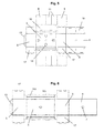
- FIG. 5 shows the one-piece blank from which the cuboid shelf boxes 2, as in the FIGS. 2 and 3 be unfolded shown.
- the first side wall 5, the second side wall 6 are hinged opposite each other.
- the shelf cover 4 is articulated on the second side.
- the tab 13 is articulated on the opposite side.
- two aperture strips 16 are first attached, which form the aperture 12 in the unfolded state. Subsequently, the intermediate walls 9 and the partitions 11 are hinged to the strips via a base element 15. In the shelf 4, the lugs 14 are also recognizable.
- FIG. 6 shows a one-piece blank for a further embodiment of the cuboid shelf box 2.
- the shelf box is designed without partitions and without partitions.
- the first side wall 5 and the second side wall 6 are also hinged to the right and left.
- the tab 13 connects.
- the second side wall 6 of the shelf 4 connects.
- each connect to the short sides of the side walls reinforcing elements 17.
- strips 16 a and 16 b are arranged, which form the front and the back of the aperture 12.
Landscapes
- Cartons (AREA)
- Display Racks (AREA)
Abstract
Description
- Gegenstand der Erfindung ist ein variables Regal umfassend mindestens zwei quaderförmige Regalkästen, aufweisend einen Regalboden, einen Regaldeckel und zwei senkrecht zu Boden und Deckel angeordnete Seitenwände, wobei die Regalkästen vertikal aufeinander gestapelt sind.
- Regale werden in verschiedenen Variationen zur Präsentation von Waren genutzt. Die Regale müssen stabil sein und sollen eine möglichst ansprechende Zurschaustellung der im Regal befindlichen Objekte erlauben. Für Aktionsware werden dabei auch bereits mit der Ware bestückte Regale, beispielsweise aus Pappe, Wellpappe oder Kunststoff verwendet. Diese haben den Vorteil, dass sie kostengünstig herstellbar sind, an die Form und Art der Ware anpassbar sind und aufgrund ihres geringen Gewichtes leicht zum Verkaufsort bzw. zum Präsentationsort transportiert werden können. Bedingt durch den Transport sind die Regale jedoch häufig nur in Standardformen verfügbar, um den Transport zu erleichtern. Zudem sind viele Regale nur von einer Seite zugänglich und müssen deshalb am Verkaufsort an der Wand platziert werden.
- Aus der
DE 10 2013 001 415 A1 ist ein Regal aus Pappe oder Wellpappe bekannt, dass eine Vielzahl von Regalböden aufweist, die von vier Seiten zugänglich sind. Das Regal weist bei geringem Materialeinsatz eine gute Zugänglichkeit auf. Allerdings muss es nach dem Transport erst zusammengebaut werden und hat dann eine festgelegte Form. - Die
DE 20 2010 001850 U1 beschreibt ein Pappmöbel mit Regalböden, bei dem die Regalböden an den Träger angeklappt werden können. Hierdurch ist ein platzsparender Transport möglich. Das Regal weist jedoch eine klassische Rückwand auf, so dass die Waren nur von einer Seite zugänglich sind. - Aufgabe der vorliegenden Erfindung ist es, ein Regal bereitzustellen, dass bei geringem Gewicht eine hohe Stabilität aufweist, eine ansprechende Präsentation der Waren ermöglicht und eine Aufstellung des Regals auch mittig im Raum, so dass die Waren von mehreren Seiten zugänglich sind. Das Regal soll zudem leicht zu transportieren sein.
- Die Aufgabe wird erfindungsgemäß gelöst durch ein variables Regal umfassend mindestens zwei quaderförmige Regalkästen, aufweisend einen Regalboden, einen Regaldeckel und zwei senkrecht zu Boden und Deckel angeordnete Seitenwände, bevorzugt zueinander parallel angeordnete, einander gegenüberliegende Seitenwände, wobei die Regalkästen vertikal aufeinander gestapelt sind,
dadurch gekennzeichnet dass - der Regalboden und der Regaldeckel jeweils eine Öffnung, vorzugsweise mittig, aufweisen,
- durch je mindestens ein Öffnung jedes quaderförmigen Regalkasten des Regals ein stabförmiges Verbindungselement geführt ist,
- die Regalkästen durch das Verbindungselement miteinander verbunden sind und
- die quaderförmigen Regalkästen 360° drehbar um das Verbindungselement sind.
- Weitere Ausführungsform sind Gegenstand der Unteransprüche oder nachfolgend beschrieben.
- Das erfindungsgemäße variable Regal weist bevorzugt Regalkästen mit zwei Seitenwänden auf, wobei die Seitenwände zueinander parallel angeordnet sind und an einander gegenüberliegenden Kanten des Regalbodens und/oder des Regaldeckels eines quaderförmigen Regalkasten angelenkt sind. Der Regalkasten besteht bevorzugt aus einem einteiligen Zuschnitt, wobei der Zuschnitt mindestens einen Regalboden, einen Regaldeckel und zwei Seitenwände hat und bevorzugt Verbindungslaschen zum Verbinden des Regalbodens bzw. des Regaldeckel mit der gegenüberliegenden Seitenwand. Die quaderförmigen Regalkästen des erfindungsgemäßen Regals sind bevorzugt von zwei Seiten, d.h. von der Vorderseite und der Rückseite zugänglich. Dieses ermöglicht bei der Präsentation von Waren eine bessere Zugangsmöglichkeit des Kunden.
- Die Öffnung im Regalboden bzw. im Regaldeckel ist, wenn sie als mittige Öffnung ausgeführt ist, bevorzugt mittig im Kreuzungspunkt der Flächendiagonalen des Regalbodens oder des Regaldeckels angeordnet. In einer weiteren Ausführungsform ist die Öffnung exzentrisch angeordnet. Wenn die exzentrische Öffnung nahe einer der Ecken angeordnet ist, sind die Regalkästen fächerförmig aufschwenkbar. Bevorzugt ist die Öffnung kreisrund, rechteckig, vieleckig oder oval ausgestaltet, besonders bevorzugt kreisrund. Die Öffnung ist aus dem Regalboden bzw. dem Regaldeckel bevorzugt ausgestanzt oder ausgeschnitten.
- Das stabförmige Verbindungselement wird durch die Öffnungen der Regalkästen geführt. Dabei kommt jeweils der Regalboden eines ersten Regalkasten auf dem Regaldeckel eines zweiten Regalkasten zu liegen. In einer bevorzugten Ausführungsform wird das stabförmige Verbindungselement jeweils sowohl durch die Öffnung im Regalboden als auch durch die Öffnung im Regaldeckel geführt. Bei der Verbindung von zwei Regalkästen ist das stabförmige Verbindungselement entsprechend dann durch vier Öffnungen geführt. Die quaderförmigen Regalkästen sind um das stabförmige Verbindungselement drehbar, wobei eine Drehung um 360° möglich ist. Das Verbindungselement ist vertikal angeordnet und bildet den Drehpunkt, um den die Regalkästen variabel verdreht werden können.
- Das stabförmige Verbindungselement ist bevorzugt ein Rohr, eine Stange oder ein Stab, bevorzugt mit einem kreisförmigen Querschnitt. Besonders bevorzugt ist das stabförmige Verbindungselement ein Papprohr. Es ist auch möglich ein Vierkantelement oder einen Stab mit z.B. sternförmigem Querschnitt zu verwenden, was erfindungsgemäß weniger bevorzugt ist. Der Durchmesser des stabförmigen Verbindungselements hängt von der Größe des Regals ab. Bevorzugt weist das Papprohr mindestens einen Durchmesser größer 10mm auf. Bei einem Regal mit einer Grundfläche von 60mm x 400 mm weist das Papprohr beispielsweise einen Durchmesser von 50 mm auf.
- Die quaderförmigen Regalkästen bestehen bevorzugt aus Wellpappe, Pappe, Papier, Karton, Kunststoff oder einer Mischung hieraus. Bevorzugt bestehen die quaderförmigen Regalkästen des erfindungsgemäßen Regals aus Wellpappe. Das Regal kann auf herkömmliche Art und Weise bedruckt, gefärbt oder beklebt sein.
- Das erfindungsgemäße Regal weist bevorzugt zwei bis sechs, besonders bevorzugt 3 bis 5 oder 3 bis 6 oder 2 bis 5, weiter bevorzugt vier miteinander verbundene quaderförmigen Regalkästen auf.
- In einer Ausführungsform weisen die quaderförmigen Regalkästen zusätzlich je mindestens eine Zwischenwand auf. Die Zwischenwand ist senkrecht zum Regalboden bzw. senkrecht zum Regaldeckel angeordnet und verläuft zwischen den zwei einander gegenüberliegenden Seitenwänden. Die Zwischenwand wird insbesondere verwendet, wenn im Regal schwerere Waren gelagert werden sollen. Durch die Zwischenwände wird die Stabilität der Regalkästen erhöht. Bevorzugt weisen die quaderförmigen Regalkästen je zwei zueinander parallele Zwischenwände auf, wobei besonders bevorzugt zwischen den Zwischenwänden ein Hohlraum gebildet ist, in dem das stabförmige Verbindungselement geführt wird. Dieses hat den Vorteil, dass das stabförmige Verbindungselement von außen nicht zu sehen ist und eine ansprechende Optik des Regals gegeben ist. Das stabförmige Verbindungselement ist so auch vor Beschädigungen durch die im Regal befindliche Ware geschützt. Zudem erhöht sich bei der Verwendung von zwei parallel zueinander angeordneten Zwischenwänden die Stabilität des Regalkastens deutlich.
- Der Regalkasten kann in einer Ausführungsform zusätzlich Trennwände aufweisen, die das Innere des Kastens in mehrere Fächer aufteilen. Die Trennwände sind beispielsweise parallel zu den Seitenwänden angeordnet und verlaufen vom Regalboden zum Regaldeckel. Weiterhin kann der Regalkasten eine Blende aufweisen, die beispielsweise als Krempelrand ausgeführt ist. Die Blende ist an der Vorderseite des Regalbodens angeordnet und verhindert, dass im Regalfach befindliche Waren nach vorne aus dem Regal fallen können. Bei dem erfindungsgemäßen Regal kann eine Blende auch an beiden offenen Seiten des Regalbodens senkrecht zu den Seitenwänden angeordnet sein.
- Der Vorteil des erfindungsgemäßen Regals ist, dass die quaderförmigen Regalkästen in beliebiger Weise zueinander verdreht angeordnet werden können. Im Ausgangszustand sind alle Regalkästen gerade in eine Richtung gedreht, um einen sicheren und sparsamen Versand zu gewährleisten. Die Regalkästen befinden sich dann in einer Flucht und das Regal ist optisch nicht von einem herkömmlichen quaderförmigen Regal zu unterscheiden. Bevorzugt können die Regalkästen durch eine Versandsicherung, beispielsweise in Form einer Versandhaube oder eines zweiten stabförmige Verbindungselemente, dass durch eine zweite Öffnung geschoben wird, gegen ein Verdrehen gesichert werden. Am Einsatzort, zum Beispiel am Verkaufsort, wird die Versandsicherung entfernt und die Regalkästen können in alle Richtungen gedreht werden. Das ermöglicht dem Endverbraucher eine 360° Sicht auf das Regal und verleiht dem Regal eine ungewöhnliche und ansprechende Optik. In einer Variation sind die Regalkästen um 90° zueinander verdreht, so dass eine Stapeloptik entsteht. In einer weiteren Variation sind die Regalkästen abwechselnd um jeweils 45° zueinander verdreht, so dass bei vier gestapelten Regalkästen der unterste und der oberste Regalkasten kongruent zueinander sind.
- Die Erfindung wird anhand der nachfolgenden Figuren näher erläutert. Es zeigen
- Figur 1
- eine perspektivische Ansicht eines erfindungsgemäßen Regals,
- Figur 2
- eine perspektivische Durchsicht einer Ausführungsform eines erfindungsgemäßen Regalkasten,
- Figur 3
- eine perspektivische Ansicht von der Unterseite eines Regalkasten gemäß
Figur 2 , - Figur 4
- eine perspektivische Ansicht des Regals gemäß
Figur 1 mit verdrehten Regalkästen, - Figur 5
- einen Zuschnitt für den Regalkasten gemäß
Figur 2 , - Figur 6
- einen Zuschnitt für einen weiteren Regalkasten.
-
Figur 1 zeigt eine Ausführungsform des erfindungsgemäßen variablen Regals 1. Das Regal 1 weist vier quaderförmige Regalkästen 2 auf, die kongruent zueinander in einer Flucht angeordnet sind. Es ist erkennbar, dass der oberste Regalkasten 2 im Regaldeckel 4 eine Öffnung 7 aufweist, die zur Aufnahme des stabförmige Verbindungselements 8 dient. Die Regalkästen weisen jeweils Zwischenwände 9 und dazu senkrechte Trennwände 11 auf. Nach vorne werden die Regalkästen durch eine Blende 12 begrenzt. Es ist erkennbar, dass der Regaldeckel 4 mit der Seitenwand 6 über eine Lasche 13 verbunden ist. - Aus
Figur 2 ist erkennbar, dass der quaderförmige Regalkasten 2 im Regalboden 3 eine Öffnung 7b und im Regaldeckel 4 eine Öffnung 7a aufweist. Der Regalkasten 2 hat 2 Zwischenwände 9a und 9b, die parallel zueinander verlaufen. Die Zwischenwände 9a und 9b bilden einen Hohlraum 10, indem die Öffnungen 7a und 7b angeordnet sind. Der Hohlraum 10 dient dazu, dass das stabförmige Verbindungselement 8 (nicht dargestellt) durch den Regalkasten geführt werden kann, ohne von außen sichtbar zu sein. Zusätzlich erhöhen die Zwischenwände 9a und 9b die Stabilität des quaderförmigen Regalkasten 2. -
Figur 3 zeigt den quaderförmigen Regalkasten 2 ausFigur 2 von der Unterseite. Im Regalboden 3 sind Nasen 14 erkennbar, mit denen der unterste Kasten an einer Palette oder einem anderen Unterteil befestigt werden kann. In der gezeigten Ausführungsform sind die Nasen 14 kreuzförmig um die Öffnung 7 angeordnet. - In
Figur 4 ist das variable Regal ausFigur 1 dargestellt, wobei die quaderförmigen Regalkästen 2 gegeneinander verdreht sind. Hierdurch werden die Regaldeckel 4 teilweise frei und sind erkennbar. -
Figur 5 zeigt den einteiligen Zuschnitt, aus dem die quaderförmigen Regalkästen 2, wie in denFiguren 2 und 3 dargestellt aufgefaltet werden. An den Boden 3 sind einander gegenüberliegend die erste Seitenwand 5 die zweite Seitenwand 6 angelenkt. An die zweite Seitenwand 6 ist an der zweiten Seite der Regaldeckel 4 angelenkt. An die erste Seitenwand 5 ist an der gegenüberliegenden Seite die Lasche 13 angelenkt. An die beiden Längsseiten des Regalbodens 3 sind zunächst zwei Blendenstreifen 16 befestigt, die im aufgefalteten Zustand die Blende 12 bilden. An die Streifen anschließend sind über ein Bodenelement 15 die Zwischenwände 9 und die Trennwände 11 angelenkt. Im Regalboden 4 sind zudem die Nasen 14 erkennbar. -
Figur 6 zeigt einen einteiligen Zuschnitt für eine weitere Ausführungsform des quaderförmigen Regalkasten 2. Der Regalkasten ist ohne Zwischenwände und ohne Trennwände ausgeführt. An den zentralen Regalboden 3 sind ebenfalls rechts und links die erste Seitenwand 5 und die zweite Seitenwand 6 angelenkt. An die erste Seitenwand 5 schließt die Lasche 13 an. An die zweite Seitenwand 6 schließt der Regalboden 4 an. Zudem schließen jeweils an die kurzen Seiten der Seitenwände Verstärkungselemente 17 an. An die Längsseite des Bodens 3 sind 2 Streifen 16a und 16b angeordnet, die die Vorderseite und die Rückseite der Blende 12 bilden. -
- variables Regal
- 1
- quaderförmiger Regalkasten
- 2
- Regalboden
- 3
- Regaldeckel
- 4
- erste Seitenwand
- 5
- zweite Seitenwand
- 6
- Öffnung
- 7
- stabförmiges Verbindungselement
- 8
- Zwischenwände
- 9
- Hohlraum
- 10
- Trennwand
- 11
- Blende
- 12
- Lasche
- 13
- Nase
- 14
- Bodenelement
- 15
- Blendenstreifen
- 16
- Verstärkungselement
- 17
Claims (8)
- Variables Regal (1) umfassend mindestens zwei quaderförmige Regalkästen (2), aufweisend einen Regalboden (3), einen Regaldeckel (4) und zwei senkrecht zu Boden und Deckel angeordnete Seitenwände (5, 6), wobei die Regalkästen (2) vertikal aufeinander gestapelt sind,
dadurch gekennzeichnet dass• der Regalboden (3) und der Regaldeckel (4) jeweils eine Öffnung (7) aufweisen,• ein stabförmiges Verbindungselement (8) durch mindestens ein Öffnung (7) jedes quaderförmigen Regalkasten (2) des Regals geführt ist,• die Regalkästen (2) durch das Verbindungselement (8) miteinander verbunden sind und• die quaderförmigen Regalkästen (2) 360° drehbar um das Verbindungselement (8) sind. - Variables Regal (1) gemäß Anspruch 1, dadurch gekennzeichnet, dass die Seitenwände (5,6), zueinander parallel angeordnet sind und an einander gegenüberliegenden Kanten des Regalbodens (3) und/oder des Regaldeckels (4) angelenkt sind.
- Variables Regal (1) gemäß Anspruch 1 oder 2, dadurch gekennzeichnet, dass die Öffnung (7) mittig angeordnet ist, bevorzugt mittig im Kreuzungspunkt der Flächendiagonalen des Regalbodens oder des Regaldeckels.
- Variables Regal (1) gemäß einem der vorhergehenden Ansprüche, dadurch gekennzeichnet, dass das stabförmige Verbindungselement (8) ein Rohr, eine Stange oder ein Stab ist, bevorzugt mit einem kreisförmigen Querschnitt, besonders bevorzugt ein Papprohr.
- Variables Regal (1) gemäß einem der vorhergehenden Ansprüche, dadurch gekennzeichnet, dass die quaderförmigen Regalkästen (2) aus Wellpappe, Pappe, Papier, Karton oder Kunststoff, bevorzugt aus Wellpappe bestehen.
- Variables Regal (1) gemäß einem der vorhergehenden Ansprüche, dadurch gekennzeichnet, dass das Regal (1) zwei bis 6, bevorzugt 3 bis 5, besonders bevorzugt vier miteinander verbundene quaderförmigen Regalkästen (2) aufweist.
- Variables Regal (1) gemäß einem der vorhergehenden Ansprüche, dadurch gekennzeichnet, dass die quaderförmigen Regalkästen (2) Zwischenwände (9) aufweisen, die senkrecht zum Regalboden (3) angeordnet sind und zwischen den zwei einander gegenüberliegenden Seitenwänden (5,6) verlaufen.
- Variables Regal (1) gemäß einem der vorhergehenden Ansprüche, dadurch gekennzeichnet, dass die quaderförmigen Regalkästen (2) je zwei zueinander parallele Zwischenwände (9) aufweisen und bevorzugt zwischen den Zwischenwänden (9) ein Hohlraum (10) gebildet ist, in dem das stabförmige Verbindungselement (8) geführt wird.
Priority Applications (1)
| Application Number | Priority Date | Filing Date | Title |
|---|---|---|---|
| PL14194692T PL2883480T3 (pl) | 2013-12-12 | 2014-11-25 | Zmienialny display regałowy |
Applications Claiming Priority (1)
| Application Number | Priority Date | Filing Date | Title |
|---|---|---|---|
| DE201320010977 DE202013010977U1 (de) | 2013-12-12 | 2013-12-12 | variables Regaldisplay |
Publications (3)
| Publication Number | Publication Date |
|---|---|
| EP2883480A2 true EP2883480A2 (de) | 2015-06-17 |
| EP2883480A3 EP2883480A3 (de) | 2015-07-08 |
| EP2883480B1 EP2883480B1 (de) | 2020-07-29 |
Family
ID=50480051
Family Applications (1)
| Application Number | Title | Priority Date | Filing Date |
|---|---|---|---|
| EP14194692.1A Revoked EP2883480B1 (de) | 2013-12-12 | 2014-11-25 | Variables Regaldisplay |
Country Status (3)
| Country | Link |
|---|---|
| EP (1) | EP2883480B1 (de) |
| DE (1) | DE202013010977U1 (de) |
| PL (1) | PL2883480T3 (de) |
Cited By (2)
| Publication number | Priority date | Publication date | Assignee | Title |
|---|---|---|---|---|
| DE202017100401U1 (de) | 2017-01-26 | 2017-02-09 | Panther Packaging Gmbh & Co. Kg | Modulares Display-System und Zuschnitte hierfür |
| CN113208313A (zh) * | 2021-05-31 | 2021-08-06 | 中航电测仪器股份有限公司 | 一种可变货道的货架 |
Families Citing this family (6)
| Publication number | Priority date | Publication date | Assignee | Title |
|---|---|---|---|---|
| CN104323592A (zh) * | 2014-10-23 | 2015-02-04 | 沈阳建筑大学 | 一种可旋转多格组合收纳柜 |
| DE102015201725A1 (de) * | 2015-02-02 | 2016-08-04 | Procédés Chénel International | Raumteiler mit mehreren zueinander schwenkbaren, im Wesentlichen quaderförmigen Raumteilerelementen |
| CN104921519A (zh) * | 2015-05-21 | 2015-09-23 | 上海交通大学 | 魔方式展示柜 |
| CN105105531A (zh) * | 2015-09-23 | 2015-12-02 | 沈阳建筑大学 | 一种随意组合可旋转多格储物柜及其组装方法 |
| IT201700020743A1 (it) * | 2017-02-23 | 2018-08-23 | Calzavara S P A | Struttura a scopo decorativo e/o tecnico, utilizzabile per esempio come arredo urbano. |
| KR102511630B1 (ko) * | 2022-03-03 | 2023-03-16 | 이상훈 | 모듈형 가구 |
Citations (3)
| Publication number | Priority date | Publication date | Assignee | Title |
|---|---|---|---|---|
| NL1017957C2 (nl) | 2001-04-27 | 2002-10-29 | Pozo Negro Beheer B V | Ligger en samenstel van ten minste één ligger en een opbouw. |
| DE202010001850U1 (de) | 2010-01-29 | 2011-06-01 | Stange, Hans-Peter, 12307 | Pappmöbel mit Regalboden |
| DE102013001415A1 (de) | 2012-01-30 | 2013-08-01 | Hans-Peter Stange | Regal aus einem knickbaren flächigen Material wie Pappe oder Wellpappe |
Family Cites Families (4)
| Publication number | Priority date | Publication date | Assignee | Title |
|---|---|---|---|---|
| FR2172478A5 (de) * | 1972-02-14 | 1973-09-28 | Petit Gilles | |
| DE8429378U1 (de) | 1984-10-04 | 1985-05-02 | Stange, Hans-Peter, 1000 Berlin | Ausstellungs-traeger aus wellpappe |
| DE19502726C2 (de) * | 1995-01-28 | 1996-12-12 | Anette Franziska Ponholzer | Zerlegbares Schrankmöbel |
| DE202010003892U1 (de) | 2010-03-20 | 2010-07-15 | Cde Creative Display Europe Gmbh | Verkaufsaufsteller |
-
2013
- 2013-12-12 DE DE201320010977 patent/DE202013010977U1/de not_active Expired - Lifetime
-
2014
- 2014-11-25 PL PL14194692T patent/PL2883480T3/pl unknown
- 2014-11-25 EP EP14194692.1A patent/EP2883480B1/de not_active Revoked
Patent Citations (3)
| Publication number | Priority date | Publication date | Assignee | Title |
|---|---|---|---|---|
| NL1017957C2 (nl) | 2001-04-27 | 2002-10-29 | Pozo Negro Beheer B V | Ligger en samenstel van ten minste één ligger en een opbouw. |
| DE202010001850U1 (de) | 2010-01-29 | 2011-06-01 | Stange, Hans-Peter, 12307 | Pappmöbel mit Regalboden |
| DE102013001415A1 (de) | 2012-01-30 | 2013-08-01 | Hans-Peter Stange | Regal aus einem knickbaren flächigen Material wie Pappe oder Wellpappe |
Cited By (3)
| Publication number | Priority date | Publication date | Assignee | Title |
|---|---|---|---|---|
| DE202017100401U1 (de) | 2017-01-26 | 2017-02-09 | Panther Packaging Gmbh & Co. Kg | Modulares Display-System und Zuschnitte hierfür |
| EP3354168A1 (de) | 2017-01-26 | 2018-08-01 | Panther Packaging GmbH & Co. KG | Modulares display-system |
| CN113208313A (zh) * | 2021-05-31 | 2021-08-06 | 中航电测仪器股份有限公司 | 一种可变货道的货架 |
Also Published As
| Publication number | Publication date |
|---|---|
| PL2883480T3 (pl) | 2020-12-14 |
| DE202013010977U1 (de) | 2014-03-20 |
| EP2883480A3 (de) | 2015-07-08 |
| EP2883480B1 (de) | 2020-07-29 |
Similar Documents
| Publication | Publication Date | Title |
|---|---|---|
| EP2883480B1 (de) | Variables Regaldisplay | |
| EP3371066B1 (de) | Kartoneinlage zum verpacken von flaschenartigen behältnissen | |
| DE202014106151U1 (de) | Regaldisplay mit variabler Breite | |
| DE102013001415B4 (de) | Regal aus einem knickbaren flächigen Material wie Pappe oder Wellpappe | |
| DE202014104940U1 (de) | Transportbehälter | |
| EP3247648B1 (de) | Displaybehälter | |
| DE202009007698U1 (de) | Verpackungssystem | |
| DE102014116535B4 (de) | Wellpappenverpackung mit automatisch umklappender Stapelecke | |
| EP3354168B1 (de) | Modulares display-system | |
| DE60314612T2 (de) | Behälter | |
| DE202018005977U1 (de) | Selbst aufbaubare, stapelbare Kiste | |
| EP3354167B2 (de) | Displaysockel mit warenfach im sockel | |
| DE102016105236B4 (de) | Faltkarton mit einem Gefache | |
| DE102011116239A1 (de) | Sockel für mindestens einen darauf aufzuständernden Warenständer | |
| DE102024101966A1 (de) | Warenregal zur Lagerung und Präsentation von Produkten | |
| DE202015102337U1 (de) | Schnell auffaltbare Display-Etagere | |
| EP3064442B1 (de) | Faltbarer verpackungsbehälter sowie zuschnitt für einen faltbaren verpackungsbehälter | |
| DE102016118222B4 (de) | Wellpappenverpackung mit Stapelecken | |
| DE102016216129A1 (de) | Pappregal und Verfahren zum Aufstellen eines Pappregals | |
| DE202016106059U1 (de) | Schnell aufstellbares Display mit Regalfächern | |
| DE102008035528A1 (de) | Schachtel zum Aufnehmen von Schalen mit Inhalt | |
| DE202021103322U1 (de) | Schnellaufstellbare Schütte mit Gefache und Zuschnitt zum Aufbau der Schütte | |
| DE102015210214A1 (de) | Pappregal | |
| DE202011003945U1 (de) | Boden-Display zum Präsentieren von Flaschen und gleichzeitig Transportverpackung | |
| DE202012005947U1 (de) | Behälterträger |
Legal Events
| Date | Code | Title | Description |
|---|---|---|---|
| PUAL | Search report despatched |
Free format text: ORIGINAL CODE: 0009013 |
|
| PUAI | Public reference made under article 153(3) epc to a published international application that has entered the european phase |
Free format text: ORIGINAL CODE: 0009012 |
|
| 17P | Request for examination filed |
Effective date: 20141125 |
|
| AK | Designated contracting states |
Kind code of ref document: A2 Designated state(s): AL AT BE BG CH CY CZ DE DK EE ES FI FR GB GR HR HU IE IS IT LI LT LU LV MC MK MT NL NO PL PT RO RS SE SI SK SM TR |
|
| AX | Request for extension of the european patent |
Extension state: BA ME |
|
| AK | Designated contracting states |
Kind code of ref document: A3 Designated state(s): AL AT BE BG CH CY CZ DE DK EE ES FI FR GB GR HR HU IE IS IT LI LT LU LV MC MK MT NL NO PL PT RO RS SE SI SK SM TR |
|
| AX | Request for extension of the european patent |
Extension state: BA ME |
|
| RIC1 | Information provided on ipc code assigned before grant |
Ipc: A47F 5/11 20060101ALI20150601BHEP Ipc: A47F 5/05 20060101AFI20150601BHEP Ipc: A47B 87/02 20060101ALI20150601BHEP |
|
| R17P | Request for examination filed (corrected) |
Effective date: 20150930 |
|
| RBV | Designated contracting states (corrected) |
Designated state(s): AL AT BE BG CH CY CZ DE DK EE ES FI FR GB GR HR HU IE IS IT LI LT LU LV MC MK MT NL NO PL PT RO RS SE SI SK SM TR |
|
| GRAP | Despatch of communication of intention to grant a patent |
Free format text: ORIGINAL CODE: EPIDOSNIGR1 |
|
| STAA | Information on the status of an ep patent application or granted ep patent |
Free format text: STATUS: GRANT OF PATENT IS INTENDED |
|
| INTG | Intention to grant announced |
Effective date: 20190826 |
|
| GRAS | Grant fee paid |
Free format text: ORIGINAL CODE: EPIDOSNIGR3 |
|
| TPAC | Observations filed by third parties |
Free format text: ORIGINAL CODE: EPIDOSNTIPA |
|
| GRAA | (expected) grant |
Free format text: ORIGINAL CODE: 0009210 |
|
| STAA | Information on the status of an ep patent application or granted ep patent |
Free format text: STATUS: THE PATENT HAS BEEN GRANTED |
|
| AK | Designated contracting states |
Kind code of ref document: B1 Designated state(s): AL AT BE BG CH CY CZ DE DK EE ES FI FR GB GR HR HU IE IS IT LI LT LU LV MC MK MT NL NO PL PT RO RS SE SI SK SM TR |
|
| REG | Reference to a national code |
Ref country code: CH Ref legal event code: EP |
|
| REG | Reference to a national code |
Ref country code: AT Ref legal event code: REF Ref document number: 1294796 Country of ref document: AT Kind code of ref document: T Effective date: 20200815 |
|
| REG | Reference to a national code |
Ref country code: IE Ref legal event code: FG4D Free format text: LANGUAGE OF EP DOCUMENT: GERMAN |
|
| REG | Reference to a national code |
Ref country code: DE Ref legal event code: R096 Ref document number: 502014014516 Country of ref document: DE |
|
| REG | Reference to a national code |
Ref country code: LT Ref legal event code: MG4D |
|
| REG | Reference to a national code |
Ref country code: NL Ref legal event code: MP Effective date: 20200729 |
|
| PG25 | Lapsed in a contracting state [announced via postgrant information from national office to epo] |
Ref country code: HR Free format text: LAPSE BECAUSE OF FAILURE TO SUBMIT A TRANSLATION OF THE DESCRIPTION OR TO PAY THE FEE WITHIN THE PRESCRIBED TIME-LIMIT Effective date: 20200729 Ref country code: PT Free format text: LAPSE BECAUSE OF FAILURE TO SUBMIT A TRANSLATION OF THE DESCRIPTION OR TO PAY THE FEE WITHIN THE PRESCRIBED TIME-LIMIT Effective date: 20201130 Ref country code: SE Free format text: LAPSE BECAUSE OF FAILURE TO SUBMIT A TRANSLATION OF THE DESCRIPTION OR TO PAY THE FEE WITHIN THE PRESCRIBED TIME-LIMIT Effective date: 20200729 Ref country code: NO Free format text: LAPSE BECAUSE OF FAILURE TO SUBMIT A TRANSLATION OF THE DESCRIPTION OR TO PAY THE FEE WITHIN THE PRESCRIBED TIME-LIMIT Effective date: 20201029 Ref country code: ES Free format text: LAPSE BECAUSE OF FAILURE TO SUBMIT A TRANSLATION OF THE DESCRIPTION OR TO PAY THE FEE WITHIN THE PRESCRIBED TIME-LIMIT Effective date: 20200729 Ref country code: BG Free format text: LAPSE BECAUSE OF FAILURE TO SUBMIT A TRANSLATION OF THE DESCRIPTION OR TO PAY THE FEE WITHIN THE PRESCRIBED TIME-LIMIT Effective date: 20201029 Ref country code: GR Free format text: LAPSE BECAUSE OF FAILURE TO SUBMIT A TRANSLATION OF THE DESCRIPTION OR TO PAY THE FEE WITHIN THE PRESCRIBED TIME-LIMIT Effective date: 20201030 Ref country code: FI Free format text: LAPSE BECAUSE OF FAILURE TO SUBMIT A TRANSLATION OF THE DESCRIPTION OR TO PAY THE FEE WITHIN THE PRESCRIBED TIME-LIMIT Effective date: 20200729 Ref country code: LT Free format text: LAPSE BECAUSE OF FAILURE TO SUBMIT A TRANSLATION OF THE DESCRIPTION OR TO PAY THE FEE WITHIN THE PRESCRIBED TIME-LIMIT Effective date: 20200729 |
|
| PGFP | Annual fee paid to national office [announced via postgrant information from national office to epo] |
Ref country code: CZ Payment date: 20201124 Year of fee payment: 7 Ref country code: AT Payment date: 20201119 Year of fee payment: 7 Ref country code: GB Payment date: 20201120 Year of fee payment: 7 Ref country code: FR Payment date: 20201120 Year of fee payment: 7 |
|
| PG25 | Lapsed in a contracting state [announced via postgrant information from national office to epo] |
Ref country code: IS Free format text: LAPSE BECAUSE OF FAILURE TO SUBMIT A TRANSLATION OF THE DESCRIPTION OR TO PAY THE FEE WITHIN THE PRESCRIBED TIME-LIMIT Effective date: 20201129 Ref country code: LV Free format text: LAPSE BECAUSE OF FAILURE TO SUBMIT A TRANSLATION OF THE DESCRIPTION OR TO PAY THE FEE WITHIN THE PRESCRIBED TIME-LIMIT Effective date: 20200729 Ref country code: RS Free format text: LAPSE BECAUSE OF FAILURE TO SUBMIT A TRANSLATION OF THE DESCRIPTION OR TO PAY THE FEE WITHIN THE PRESCRIBED TIME-LIMIT Effective date: 20200729 |
|
| PGFP | Annual fee paid to national office [announced via postgrant information from national office to epo] |
Ref country code: PL Payment date: 20201022 Year of fee payment: 7 |
|
| PG25 | Lapsed in a contracting state [announced via postgrant information from national office to epo] |
Ref country code: NL Free format text: LAPSE BECAUSE OF FAILURE TO SUBMIT A TRANSLATION OF THE DESCRIPTION OR TO PAY THE FEE WITHIN THE PRESCRIBED TIME-LIMIT Effective date: 20200729 |
|
| REG | Reference to a national code |
Ref country code: DE Ref legal event code: R026 Ref document number: 502014014516 Country of ref document: DE |
|
| PG25 | Lapsed in a contracting state [announced via postgrant information from national office to epo] |
Ref country code: SM Free format text: LAPSE BECAUSE OF FAILURE TO SUBMIT A TRANSLATION OF THE DESCRIPTION OR TO PAY THE FEE WITHIN THE PRESCRIBED TIME-LIMIT Effective date: 20200729 Ref country code: RO Free format text: LAPSE BECAUSE OF FAILURE TO SUBMIT A TRANSLATION OF THE DESCRIPTION OR TO PAY THE FEE WITHIN THE PRESCRIBED TIME-LIMIT Effective date: 20200729 Ref country code: DK Free format text: LAPSE BECAUSE OF FAILURE TO SUBMIT A TRANSLATION OF THE DESCRIPTION OR TO PAY THE FEE WITHIN THE PRESCRIBED TIME-LIMIT Effective date: 20200729 Ref country code: EE Free format text: LAPSE BECAUSE OF FAILURE TO SUBMIT A TRANSLATION OF THE DESCRIPTION OR TO PAY THE FEE WITHIN THE PRESCRIBED TIME-LIMIT Effective date: 20200729 Ref country code: IT Free format text: LAPSE BECAUSE OF FAILURE TO SUBMIT A TRANSLATION OF THE DESCRIPTION OR TO PAY THE FEE WITHIN THE PRESCRIBED TIME-LIMIT Effective date: 20200729 |
|
| PLBI | Opposition filed |
Free format text: ORIGINAL CODE: 0009260 |
|
| PLAX | Notice of opposition and request to file observation + time limit sent |
Free format text: ORIGINAL CODE: EPIDOSNOBS2 |
|
| PG25 | Lapsed in a contracting state [announced via postgrant information from national office to epo] |
Ref country code: AL Free format text: LAPSE BECAUSE OF FAILURE TO SUBMIT A TRANSLATION OF THE DESCRIPTION OR TO PAY THE FEE WITHIN THE PRESCRIBED TIME-LIMIT Effective date: 20200729 |
|
| 26 | Opposition filed |
Opponent name: ARBEITSKREIS DISPLAY E.V. Effective date: 20210428 |
|
| PG25 | Lapsed in a contracting state [announced via postgrant information from national office to epo] |
Ref country code: SK Free format text: LAPSE BECAUSE OF FAILURE TO SUBMIT A TRANSLATION OF THE DESCRIPTION OR TO PAY THE FEE WITHIN THE PRESCRIBED TIME-LIMIT Effective date: 20200729 Ref country code: MC Free format text: LAPSE BECAUSE OF FAILURE TO SUBMIT A TRANSLATION OF THE DESCRIPTION OR TO PAY THE FEE WITHIN THE PRESCRIBED TIME-LIMIT Effective date: 20200729 |
|
| REG | Reference to a national code |
Ref country code: CH Ref legal event code: PL |
|
| PG25 | Lapsed in a contracting state [announced via postgrant information from national office to epo] |
Ref country code: LU Free format text: LAPSE BECAUSE OF NON-PAYMENT OF DUE FEES Effective date: 20201125 |
|
| REG | Reference to a national code |
Ref country code: BE Ref legal event code: MM Effective date: 20201130 |
|
| PG25 | Lapsed in a contracting state [announced via postgrant information from national office to epo] |
Ref country code: SI Free format text: LAPSE BECAUSE OF FAILURE TO SUBMIT A TRANSLATION OF THE DESCRIPTION OR TO PAY THE FEE WITHIN THE PRESCRIBED TIME-LIMIT Effective date: 20200729 Ref country code: LI Free format text: LAPSE BECAUSE OF NON-PAYMENT OF DUE FEES Effective date: 20201130 Ref country code: CH Free format text: LAPSE BECAUSE OF NON-PAYMENT OF DUE FEES Effective date: 20201130 |
|
| PLBB | Reply of patent proprietor to notice(s) of opposition received |
Free format text: ORIGINAL CODE: EPIDOSNOBS3 |
|
| PG25 | Lapsed in a contracting state [announced via postgrant information from national office to epo] |
Ref country code: IE Free format text: LAPSE BECAUSE OF NON-PAYMENT OF DUE FEES Effective date: 20201125 |
|
| PG25 | Lapsed in a contracting state [announced via postgrant information from national office to epo] |
Ref country code: TR Free format text: LAPSE BECAUSE OF FAILURE TO SUBMIT A TRANSLATION OF THE DESCRIPTION OR TO PAY THE FEE WITHIN THE PRESCRIBED TIME-LIMIT Effective date: 20200729 Ref country code: MT Free format text: LAPSE BECAUSE OF FAILURE TO SUBMIT A TRANSLATION OF THE DESCRIPTION OR TO PAY THE FEE WITHIN THE PRESCRIBED TIME-LIMIT Effective date: 20200729 Ref country code: CY Free format text: LAPSE BECAUSE OF FAILURE TO SUBMIT A TRANSLATION OF THE DESCRIPTION OR TO PAY THE FEE WITHIN THE PRESCRIBED TIME-LIMIT Effective date: 20200729 |
|
| PG25 | Lapsed in a contracting state [announced via postgrant information from national office to epo] |
Ref country code: MK Free format text: LAPSE BECAUSE OF FAILURE TO SUBMIT A TRANSLATION OF THE DESCRIPTION OR TO PAY THE FEE WITHIN THE PRESCRIBED TIME-LIMIT Effective date: 20200729 |
|
| REG | Reference to a national code |
Ref country code: AT Ref legal event code: MM01 Ref document number: 1294796 Country of ref document: AT Kind code of ref document: T Effective date: 20211125 |
|
| GBPC | Gb: european patent ceased through non-payment of renewal fee |
Effective date: 20211125 |
|
| PG25 | Lapsed in a contracting state [announced via postgrant information from national office to epo] |
Ref country code: CZ Free format text: LAPSE BECAUSE OF NON-PAYMENT OF DUE FEES Effective date: 20211125 Ref country code: BE Free format text: LAPSE BECAUSE OF NON-PAYMENT OF DUE FEES Effective date: 20201130 |
|
| PG25 | Lapsed in a contracting state [announced via postgrant information from national office to epo] |
Ref country code: AT Free format text: LAPSE BECAUSE OF NON-PAYMENT OF DUE FEES Effective date: 20211125 |
|
| PG25 | Lapsed in a contracting state [announced via postgrant information from national office to epo] |
Ref country code: GB Free format text: LAPSE BECAUSE OF NON-PAYMENT OF DUE FEES Effective date: 20211125 |
|
| PG25 | Lapsed in a contracting state [announced via postgrant information from national office to epo] |
Ref country code: FR Free format text: LAPSE BECAUSE OF NON-PAYMENT OF DUE FEES Effective date: 20211130 |
|
| REG | Reference to a national code |
Ref country code: DE Ref legal event code: R082 Ref document number: 502014014516 Country of ref document: DE Representative=s name: PATENTANWAELTE OLBRICHT, BUCHHOLD, KEULERTZ PA, DE Ref country code: DE Ref legal event code: R082 Ref document number: 502014014516 Country of ref document: DE Representative=s name: BARDEHLE PAGENBERG PARTNERSCHAFT MBB PATENTANW, DE |
|
| PG25 | Lapsed in a contracting state [announced via postgrant information from national office to epo] |
Ref country code: PL Free format text: LAPSE BECAUSE OF NON-PAYMENT OF DUE FEES Effective date: 20211125 |
|
| P01 | Opt-out of the competence of the unified patent court (upc) registered |
Effective date: 20230602 |
|
| APAH | Appeal reference modified |
Free format text: ORIGINAL CODE: EPIDOSCREFNO |
|
| APBM | Appeal reference recorded |
Free format text: ORIGINAL CODE: EPIDOSNREFNO |
|
| APBP | Date of receipt of notice of appeal recorded |
Free format text: ORIGINAL CODE: EPIDOSNNOA2O |
|
| APBM | Appeal reference recorded |
Free format text: ORIGINAL CODE: EPIDOSNREFNO |
|
| APBP | Date of receipt of notice of appeal recorded |
Free format text: ORIGINAL CODE: EPIDOSNNOA2O |
|
| APBQ | Date of receipt of statement of grounds of appeal recorded |
Free format text: ORIGINAL CODE: EPIDOSNNOA3O |
|
| APAL | Date of receipt of statement of grounds of an appeal modified |
Free format text: ORIGINAL CODE: EPIDOSCNOA3O |
|
| APBQ | Date of receipt of statement of grounds of appeal recorded |
Free format text: ORIGINAL CODE: EPIDOSNNOA3O |
|
| REG | Reference to a national code |
Ref country code: DE Ref legal event code: R082 Ref document number: 502014014516 Country of ref document: DE Representative=s name: BARDEHLE PAGENBERG PARTNERSCHAFT MBB PATENTANW, DE |
|
| REG | Reference to a national code |
Ref country code: DE Ref legal event code: R064 Ref document number: 502014014516 Country of ref document: DE Ref country code: DE Ref legal event code: R103 Ref document number: 502014014516 Country of ref document: DE |
|
| APBU | Appeal procedure closed |
Free format text: ORIGINAL CODE: EPIDOSNNOA9O |
|
| RDAF | Communication despatched that patent is revoked |
Free format text: ORIGINAL CODE: EPIDOSNREV1 |
|
| STAA | Information on the status of an ep patent application or granted ep patent |
Free format text: STATUS: PATENT REVOKED |
|
| RDAG | Patent revoked |
Free format text: ORIGINAL CODE: 0009271 |
|
| REG | Reference to a national code |
Ref country code: CH Ref legal event code: N12 Free format text: ST27 STATUS EVENT CODE: U-0-0-N10-N12 (AS PROVIDED BY THE NATIONAL OFFICE) Effective date: 20251217 |
|
| PGFP | Annual fee paid to national office [announced via postgrant information from national office to epo] |
Ref country code: DE Payment date: 20251126 Year of fee payment: 12 |
|
| 27W | Patent revoked |
Effective date: 20251201 |
|
| REG | Reference to a national code |
Ref country code: AT Ref legal event code: MA03 Ref document number: 1294796 Country of ref document: AT Kind code of ref document: T Effective date: 20251201 |