EP2882998B1 - Dispositif d'éclairage avec une structure de dissipation de chaleur - Google Patents
Dispositif d'éclairage avec une structure de dissipation de chaleur Download PDFInfo
- Publication number
- EP2882998B1 EP2882998B1 EP13783986.6A EP13783986A EP2882998B1 EP 2882998 B1 EP2882998 B1 EP 2882998B1 EP 13783986 A EP13783986 A EP 13783986A EP 2882998 B1 EP2882998 B1 EP 2882998B1
- Authority
- EP
- European Patent Office
- Prior art keywords
- heat sink
- sink structure
- lid
- lighting device
- lid portion
- Prior art date
- Legal status (The legal status is an assumption and is not a legal conclusion. Google has not performed a legal analysis and makes no representation as to the accuracy of the status listed.)
- Not-in-force
Links
Images
Classifications
-
- F—MECHANICAL ENGINEERING; LIGHTING; HEATING; WEAPONS; BLASTING
- F21—LIGHTING
- F21K—NON-ELECTRIC LIGHT SOURCES USING LUMINESCENCE; LIGHT SOURCES USING ELECTROCHEMILUMINESCENCE; LIGHT SOURCES USING CHARGES OF COMBUSTIBLE MATERIAL; LIGHT SOURCES USING SEMICONDUCTOR DEVICES AS LIGHT-GENERATING ELEMENTS; LIGHT SOURCES NOT OTHERWISE PROVIDED FOR
- F21K9/00—Light sources using semiconductor devices as light-generating elements, e.g. using light-emitting diodes [LED] or lasers
- F21K9/90—Methods of manufacture
-
- F—MECHANICAL ENGINEERING; LIGHTING; HEATING; WEAPONS; BLASTING
- F21—LIGHTING
- F21V—FUNCTIONAL FEATURES OR DETAILS OF LIGHTING DEVICES OR SYSTEMS THEREOF; STRUCTURAL COMBINATIONS OF LIGHTING DEVICES WITH OTHER ARTICLES, NOT OTHERWISE PROVIDED FOR
- F21V19/00—Fastening of light sources or lamp holders
- F21V19/001—Fastening of light sources or lamp holders the light sources being semiconductors devices, e.g. LEDs
- F21V19/0015—Fastening arrangements intended to retain light sources
-
- F—MECHANICAL ENGINEERING; LIGHTING; HEATING; WEAPONS; BLASTING
- F21—LIGHTING
- F21V—FUNCTIONAL FEATURES OR DETAILS OF LIGHTING DEVICES OR SYSTEMS THEREOF; STRUCTURAL COMBINATIONS OF LIGHTING DEVICES WITH OTHER ARTICLES, NOT OTHERWISE PROVIDED FOR
- F21V19/00—Fastening of light sources or lamp holders
- F21V19/001—Fastening of light sources or lamp holders the light sources being semiconductors devices, e.g. LEDs
- F21V19/003—Fastening of light source holders, e.g. of circuit boards or substrates holding light sources
-
- F—MECHANICAL ENGINEERING; LIGHTING; HEATING; WEAPONS; BLASTING
- F21—LIGHTING
- F21V—FUNCTIONAL FEATURES OR DETAILS OF LIGHTING DEVICES OR SYSTEMS THEREOF; STRUCTURAL COMBINATIONS OF LIGHTING DEVICES WITH OTHER ARTICLES, NOT OTHERWISE PROVIDED FOR
- F21V23/00—Arrangement of electric circuit elements in or on lighting devices
-
- F—MECHANICAL ENGINEERING; LIGHTING; HEATING; WEAPONS; BLASTING
- F21—LIGHTING
- F21V—FUNCTIONAL FEATURES OR DETAILS OF LIGHTING DEVICES OR SYSTEMS THEREOF; STRUCTURAL COMBINATIONS OF LIGHTING DEVICES WITH OTHER ARTICLES, NOT OTHERWISE PROVIDED FOR
- F21V29/00—Protecting lighting devices from thermal damage; Cooling or heating arrangements specially adapted for lighting devices or systems
- F21V29/85—Protecting lighting devices from thermal damage; Cooling or heating arrangements specially adapted for lighting devices or systems characterised by the material
- F21V29/89—Metals
-
- F—MECHANICAL ENGINEERING; LIGHTING; HEATING; WEAPONS; BLASTING
- F21—LIGHTING
- F21V—FUNCTIONAL FEATURES OR DETAILS OF LIGHTING DEVICES OR SYSTEMS THEREOF; STRUCTURAL COMBINATIONS OF LIGHTING DEVICES WITH OTHER ARTICLES, NOT OTHERWISE PROVIDED FOR
- F21V7/00—Reflectors for light sources
- F21V7/04—Optical design
-
- F—MECHANICAL ENGINEERING; LIGHTING; HEATING; WEAPONS; BLASTING
- F21—LIGHTING
- F21V—FUNCTIONAL FEATURES OR DETAILS OF LIGHTING DEVICES OR SYSTEMS THEREOF; STRUCTURAL COMBINATIONS OF LIGHTING DEVICES WITH OTHER ARTICLES, NOT OTHERWISE PROVIDED FOR
- F21V7/00—Reflectors for light sources
- F21V7/22—Reflectors for light sources characterised by materials, surface treatments or coatings, e.g. dichroic reflectors
- F21V7/24—Reflectors for light sources characterised by materials, surface treatments or coatings, e.g. dichroic reflectors characterised by the material
-
- F—MECHANICAL ENGINEERING; LIGHTING; HEATING; WEAPONS; BLASTING
- F21—LIGHTING
- F21K—NON-ELECTRIC LIGHT SOURCES USING LUMINESCENCE; LIGHT SOURCES USING ELECTROCHEMILUMINESCENCE; LIGHT SOURCES USING CHARGES OF COMBUSTIBLE MATERIAL; LIGHT SOURCES USING SEMICONDUCTOR DEVICES AS LIGHT-GENERATING ELEMENTS; LIGHT SOURCES NOT OTHERWISE PROVIDED FOR
- F21K9/00—Light sources using semiconductor devices as light-generating elements, e.g. using light-emitting diodes [LED] or lasers
- F21K9/20—Light sources comprising attachment means
- F21K9/23—Retrofit light sources for lighting devices with a single fitting for each light source, e.g. for substitution of incandescent lamps with bayonet or threaded fittings
- F21K9/232—Retrofit light sources for lighting devices with a single fitting for each light source, e.g. for substitution of incandescent lamps with bayonet or threaded fittings specially adapted for generating an essentially omnidirectional light distribution, e.g. with a glass bulb
-
- F—MECHANICAL ENGINEERING; LIGHTING; HEATING; WEAPONS; BLASTING
- F21—LIGHTING
- F21V—FUNCTIONAL FEATURES OR DETAILS OF LIGHTING DEVICES OR SYSTEMS THEREOF; STRUCTURAL COMBINATIONS OF LIGHTING DEVICES WITH OTHER ARTICLES, NOT OTHERWISE PROVIDED FOR
- F21V29/00—Protecting lighting devices from thermal damage; Cooling or heating arrangements specially adapted for lighting devices or systems
- F21V29/50—Cooling arrangements
- F21V29/502—Cooling arrangements characterised by the adaptation for cooling of specific components
- F21V29/507—Cooling arrangements characterised by the adaptation for cooling of specific components of means for protecting lighting devices from damage, e.g. housings
-
- F—MECHANICAL ENGINEERING; LIGHTING; HEATING; WEAPONS; BLASTING
- F21—LIGHTING
- F21V—FUNCTIONAL FEATURES OR DETAILS OF LIGHTING DEVICES OR SYSTEMS THEREOF; STRUCTURAL COMBINATIONS OF LIGHTING DEVICES WITH OTHER ARTICLES, NOT OTHERWISE PROVIDED FOR
- F21V29/00—Protecting lighting devices from thermal damage; Cooling or heating arrangements specially adapted for lighting devices or systems
- F21V29/50—Cooling arrangements
- F21V29/70—Cooling arrangements characterised by passive heat-dissipating elements, e.g. heat-sinks
-
- F—MECHANICAL ENGINEERING; LIGHTING; HEATING; WEAPONS; BLASTING
- F21—LIGHTING
- F21Y—INDEXING SCHEME ASSOCIATED WITH SUBCLASSES F21K, F21L, F21S and F21V, RELATING TO THE FORM OR THE KIND OF THE LIGHT SOURCES OR OF THE COLOUR OF THE LIGHT EMITTED
- F21Y2115/00—Light-generating elements of semiconductor light sources
- F21Y2115/10—Light-emitting diodes [LED]
-
- Y—GENERAL TAGGING OF NEW TECHNOLOGICAL DEVELOPMENTS; GENERAL TAGGING OF CROSS-SECTIONAL TECHNOLOGIES SPANNING OVER SEVERAL SECTIONS OF THE IPC; TECHNICAL SUBJECTS COVERED BY FORMER USPC CROSS-REFERENCE ART COLLECTIONS [XRACs] AND DIGESTS
- Y10—TECHNICAL SUBJECTS COVERED BY FORMER USPC
- Y10T—TECHNICAL SUBJECTS COVERED BY FORMER US CLASSIFICATION
- Y10T29/00—Metal working
- Y10T29/49—Method of mechanical manufacture
- Y10T29/49002—Electrical device making
- Y10T29/49117—Conductor or circuit manufacturing
- Y10T29/49124—On flat or curved insulated base, e.g., printed circuit, etc.
- Y10T29/4913—Assembling to base an electrical component, e.g., capacitor, etc.
Definitions
- the present invention generally relates to the field of lighting devices having a heat sink structure for a dissipation of heat from an electronic carrier of the lighting device.
- the present invention also relates to methods of manufacturing such lighting devices.
- Lighting devices comprising solid state light sources, such as light emitting diodes (LEDs), are known in the art. Lighting devices comprising LEDs may be used for a general lighting or even for a more specific lighting, as the color and the output power of the LEDs may be tuned. Generally, the light source(s) of the lighting devices is (are) mounted on, or at least connected to, a circuit board. The light source(s) may be arranged within an encapsulating housing, usually having the shape of a bulb. In addition to provide a maximum output of light and/or a specific color of light, the design of a lighting device needs to take into account the evacuation of heat generated by the light source(s) and/or the electronics connected to the light source(s).
- LEDs light emitting diodes
- a LED-based illumination device comprising a light source, a carrier for supporting the light source, and an envelope.
- the carrier shaped as a disc, is arranged within the envelope, wherein the edge of the carrier is in contact with the envelope along an inner circumference of the envelope.
- the carrier divides an inner space of the envelope into two parts.
- the carrier is arranged in thermal contact with the envelope along the entire axial extent of the envelope.
- WO2012/098476A1 discloses a lighting device having a light source and a drive unit arranged to drive the light source, according to the preamble of claim 1.
- the light source and the drive unit are mounted at a first respectively a second reception portion of a heat sink.
- the heat sink is a formed sheet structure which has been formed in a predetermined shape from a sheet shaped heat sink blank.
- the present invention has been made with respect to the above considerations. It is an object of the present invention to provide a lighting device with improved heat dissipation from its heat generating components in order to extend the LED lifetime, and/or to increase the light output or to reduce number of LEDs for a certain light output. It is also an object of the present invention to provide a facilitated method of manufacturing such a lighting device.
- a lighting device comprises a light source, an electronic carrier comprising a first portion for carrying the light source and a second portion for providing an electrical connection to the light source, and a heat sink structure arranged for a dissipation of heat from the electronic carrier and defining a cavity.
- the heat sink structure comprises first and a second lid portion arranged at an opening of the heat sink structure, wherein the first lid portion and the second lid portion form a lid over the cavity and substantially close the opening in a folded position.
- the first and the second lid portion in the folded position define a hole through which hole the electronic carrier extends and the first portion of the electronic carrier is supported by the first lid portion outside the cavity, and the second portion of the electronic carrier is at least partially enclosed by the heat sink structure inside the cavity.
- the second lid portion partially overlaps the first lid portion and clamps the first portion of the electronic carrier to the first lid portion in the folded position.
- a method of manufacturing a lighting device comprises providing a heat sink structure defining a cavity and comprising a first lid portion and a second lid portion arranged at an opening of the heat sink structure, and folding the first lid portion such that it partially closes the opening.
- an electronic carrier comprising a first portion for carrying a light source and a second portion for providing an electrical connection to the light source is arranged such that the electronic carrier extends through a hole defined by the first and the second lid portion and such that the first portion of the electronic carrier is supported by the first lid portion outside the cavity and the second portion of the electronic carrier is at least partially enclosed by the heat sink structure inside the cavity.
- the second lid portion is folded such that it together with the first lid portion forms a lid over the cavity and substantially close the opening of the heat sink structure and wherein the second lid portion partially overlaps the first lid portion and clamps the first portion of the electronic carrier to the first lid portion.
- the heat sink structure of the lighting device provides an improved heat dissipation compared to arrangements in the prior art.
- heat is dissipated from the first portion of the electronic carrier (and thereby also from the light source), since the first portion of the electronic carrier is supported by at least one of the lid portions of the heat sink structure.
- An improved thermal path is provided from the lid portions (or flaps) to the portion of the heat sink structure at least partially enclosing the second portion of the electronic carrier (or driver), as the lid portions and the portion of the heat sink structure, at least partially enclosing the second portion of the electronic carrier, are comprised in a common heat sink structure.
- heat is dissipated from the second portion of the electronic carrier to the heat sink structure, since the heat sink structure at least partially encloses the second portion of the electronic carrier, and thereby further provides a thermal path between the second portion and the heat sink structure.
- the heat sink structure of the present invention provides a large cooling surface, which even further increases the efficiency of the heat dissipation properties of the lighting device.
- the demands on heat dissipation from the light source and its associated electronic carrier portion are high.
- the present invention meets these heat dissipation demands, and provides an improved heat dissipation compared to arrangements in the prior art.
- the present invention provides a common heat structure (or heat sink component) comprising the at least one lid portion and the portion of the heat sink structure at least partially enclosing the second portion of the electronic carrier, the number of components of the lighting device is reduced.
- the present invention is further advantageous in that the manufacturing of the lighting device becomes more efficient due to a facilitated assembly of the lighting device.
- the common heat sink structure of the present invention provides an inexpensive manufacturing of the lighting device.
- the second portion of the electronic carrier may comprise tracks or other suitable means for providing an electrical connection to the light sources.
- current and/or voltage is supplied by driver electronics via the electrical connection to the light sources.
- the second portion may also comprise driver electronics.
- At least one of the at least one lid portion is folded such that the opening is at least partially closed by the at least one lid portion. This is advantageous in that the opening of the heat sink structure is thereby easily and conveniently closed by the first and second lid portion (lid portions), which even further contributes to a facilitated assembly of the lighting device.
- the heat sink structure and the at least one lid portion may be formed by a single piece of material.
- the present embodiment is advantageous in that the manufacturing of the lighting device is even further facilitated, as the number of components in the lighting device is even further reduced. Consequently, the lid portions do not have to be mounted to the opening of the heat sink structure during the assembly of the lighting device, as they are already connected to the heat sink structure.
- the heat sink structure and the at least one lid portion may be formed by a single piece of material, the thermal path between the lid portions and the remaining portion of the heat sink structure is improved, thereby further improving the heat dissipation from the lid portions and the first portion of the electronic carrier.
- the heat sink structure and the at least one lid portion may comprise sheet metal.
- the method of manufacturing the lighting device may comprise providing the heat sink structure by deep drawing a piece of sheet metal.
- the present embodiment is advantageous in that sheet metal has a high thermal conductivity, thereby even further improving the heat dissipation from the electronic carrier.
- the sheet metal allows deep drawing for forming the (desired) shape of the heat sink structure.
- other methods of forming the heat sink structure are also envisaged, such as rolling or stamping the sheet metal.
- the heat sink structure may be casted.
- the lighting device comprises at least two lid portions, and the second lid portion is arranged to clamp the first portion of the electronic carrier to a first lid portion.
- clamp it is here meant a clamping, holding, pressing and/or pinching of the first portion of the electronic carrier to the second lid portion.
- the second lid portion holds the first portion of the electronic carrier in place at the first lid portion.
- the mechanical clamping of the electronic carrier to the first lid portion is easily performed and/or that no adhesive is required to attach the first portion of the electronic carrier to the first lid portion, which further facilitates manufacturing as well as recycling of the lighting device.
- the second lid portion may press the first portion of the electronic carrier towards the first lid portion, the heat dissipation from the first portion of the electronic carrier to the heat sink structure becomes even further improved.
- the lighting device comprises at least two lid portions, wherein the lid portions at least partially overlap each other, which increases the thermal (and physical) contact surface between the lid portions. Further, as the material thickness is increased in the region of the overlapped lid portions, the heat dissipation from the first portion of the electronic carrier is even further improved.
- At least one of the first and second lid portion may be fixed in a folded position by a locking means.
- the locking means may thus hold the at least one lid portion in the folded position, and preferably in abutment (or physical contact) to the opening of the heat sink structure, which further improves the heat dissipation from the lid portions to the remaining portion of the heat sink structure.
- the lid portions may be arranged to define a hole (or recess), and wherein the electronic carrier is arranged to extend through the hole.
- a lid portion may comprise a recess in the edge to be mated with another lid portion, such that the opening of the heat sink structure, closed by the at least one lid portion, comprises a recess. If the at least one lid portion is folded, the recess may define a hole between the lid portions when they are in a folded position.
- the size of the hole corresponds to the size of the portion of the electronic carrier located in the hole, so as to provide a close fit of the electronic carrier in the hole, thereby even further improving the heat dissipation of the lighting device.
- the first portion of the electronic carrier is supported by the first lid portion outside a cavity defined by the heat sink structure, and the second portion of the electronic carrier is arranged inside the cavity.
- the cavity of the heat sink structure at least partially encloses the second portion of the electronic carrier.
- the portion of the heat sink structure defining the cavity may be substantially cup-shaped with two opposite openings, wherein one is closed by the at least one lid portion and the other is arranged for allowing an electrical connection between the second portion of the electronic carrier and a power supply contact of the lighting device (such as a screw base).
- the lighting device may further comprise a housing at least partially enclosing the heat sink structure.
- the present embodiment is advantageous in that the housing protects the heat sink structure from outer damage.
- the housing may be in thermal contact with the heat sink structure, such that the housing may dissipate heat from the heat sink structure to the surroundings.
- the outer shape of the heat sink structure may be at least partially conformed to the inner shape of the housing.
- the outer shape of the heat sink structure may be arranged to closely fit in the housing.
- the present embodiment is advantageous in that the (close) fit of the heat sink and the structure even further improves the heat dissipation from the heat sink structure to the housing. Further, a mounting of the heat sink structure in the housing is facilitated, as the heat sink structure easier arranges in the intended position in the housing.
- a major part of the outer shape of the heat sink structure may be conformed to the inner shape of the housing, thereby further improving the close fit of the heat sink in the housing, and consequently, also improving the heat dissipation.
- the housing may comprise an electrically insulating material, such as ceramics or plastics.
- the present embodiment is advantageous in that the housing electrically insulates the heat sink and the electronic carrier from the surroundings.
- the electrically insulating material may be adapted for dissipating heat from the heat sink structure, and may therefore preferably have a rather high thermal conductivity.
- the first portion of the electronic carrier may make an angle of 40° to 140°, preferably 60° to 120°, and most preferably 80° to 100°, with the second portion of the electronic carrier.
- the first portion may be supported by the first lid portion in a substantially horizontal position, while the second portion of the electronic carrier may extend downwards in (the cavity of) the heat sink structure in a substantially vertical direction.
- the first and second portions of the electronic carrier may be rigidly connected to each other.
- the first and second portions of the electronic carrier may be part of a single piece printed circuit board (PCB) being folded between the first and second portions to form the above described angle. It will be appreciated that the first and second portions of the electronic carrier remain electrically connected in the case at least one lid portion is folded.
- PCB printed circuit board
- At least one of the lid portions may comprise a reflective surface adapted to reflect light from the light source.
- the present embodiment is advantageous in that the light output from the lighting device is increased.
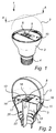
- Figure 2 is a cross section taken along line A - A in Figure 1 .
- the lighting device 1 in Figures 1 and 2 comprises an envelope (or bulb) 2, a housing 3, and a screw base 4, together enclosing the interior of the lighting device 1.
- the lighting device 1 further comprises one or more light sources 5 and a heat sink structure 10.
- the light sources 5 are arranged at a first portion 21 of an electronic carrier 20, such as a printed circuit board (PCB).
- the electronic carrier 20 further comprises a second portion 22 comprising at least an electrical connection to electronics for driving the light sources 5.
- the second portion 22 also comprises the electronics for driving the light sources 5.
- the first portion 21 of the electronic carrier 20 may hereinafter be referred to as the light source portion 21 and the second portion 22 of the electronic carrier 20 as the driver portion 22.
- the heat sink structure 10 is adapted to dissipate heat from the light sources 5 and/or the electronic carrier 20, e.g. via the housing 3, to the surroundings of the lighting device 1, wherein a dissipation of heat from the light sources 5 and/or the electronic carrier 20 extends the life time of the lighting device 1.
- the heat sink structure 10 defines a cavity 13, in which the driver portion 22 of the electronic carrier 20 is arranged, and the heat sink structure 10 further comprises an opening 14 towards the envelope 2.
- a first lid portion 11 and a second lid portion 12 are arranged at the opening 14, wherein the lid portions 11, 12 close the opening 14 or are folded so as to close the opening 14. In other words, the lid portions 11, 12 may be folded to form a lid over the cavity 13 of the heat sink structure 10.
- the heat sink structure 10 further comprises an additional opening 15, opposite to the opening 14 with the lid portions 11, 12, through which additional opening 15 the driver portion 22 (or an electrical connection to the driver portion 22) may extend for connecting the driver portion 22 to the screw base 4.
- the outer shape of the portion of the heat sink structure 10 enclosing the driver portion 22 may preferably at least partly follow the shape of the inner walls of the housing 3, thereby providing a close fit between the heat sink structure 10 and the housing which improves the thermal (and physical) contact there between.
- the housing 3 is cup-shaped, and the heat sink structure 10 therefore has a corresponding cup-shape.
- the heat sink structure 10 may extend from a base portion of the lighting device (e.g. in a vicinity of the screw base 4) to an approximate center portion of the lighting device 1, as shown in Figures 1 and 2 .
- the lid portions 11, 12 provide a horizontal definition within the lighting device 1
- the envelope 2 and the heat sink structure 10 defines a single compartment above the lid portions 11, 12 at least partially enclosing the light sources 5.
- the single compartment may be free from further elements and/or components, which in turn prevents an optical obstruction for the light emitted by the light sources 5 during operation.
- the lighting device 1 of the present invention provides a homogeneous, substantially omnidirectional light distribution from the light sources 5.
- the lid portions 11, 12 may be arranged (or folded) so as to abut an edge of the opening 14 (i.e. to abut the portion of the heat sink structure 10 enclosing the driver portion 22 of the electronic carrier 20).
- the lighting device 1 may comprise locking means (not shown).
- the locking means may e.g. comprise one or more (small) protrusion(s) on the inside of the housing 3, located closely above the heat sink structure 10. This arrangement allows a snap fitting of the lid portions 11, 12, such that the protrusion(s) hold(s) the lid portions 11, 12 in the folded position.
- the locking means may be formed by features in one or more of the lid portions 11, 12, such as a protrusion in one of the lid portions 11, 12 arranged to be mated with a recess in the other lid portion 11, 12.
- Other locking means may also be envisaged.
- the lid portions 11, 12 (e.g. after folding the lid portions 11, 12 into the folded position (state)) define a hole (or recess) 17 in the heat sink structure 10, through which hole 17 the electronic carrier 20 extends through, such that the light source portion 21 is supported by the first lid portion 11 and the driver portion 22 is at least partially enclosed by the heat sink structure 10 in the cavity 13.
- the light source portion 21 of the electronic carrier 20 preferably makes an angle with the driver portion 22 of 40° to 140°, preferably 60° to 120°, and most preferably 80° to 100°, such as around 90 °, whereby the light source portion 21 is supported by the first lid portion 11 in a substantially horizontal plane and the driver portion 22 extends downwards in the cavity 13 in a substantially vertical plane.
- the lid portions 11, 12 enable having a single electronic carrier 20 for both carrying and driving the light sources 5, whereby a heat sink portion (i.e. the first lid portion 11) supports and cools the light source portion 21 of the electronic carrier 20.
- the second lid portion 12 may partially overlap the first lid portion 11 and preferably also clamp the light source portion 21 to the first lid portion 11.
- the second lid portion 12 may e.g. comprise an edge 16 arranged to overlap a portion of the light source portion 21, thereby forcing the light source portion 21 towards the first lid portion 11.
- the overlapping of the edge 16 and the light source portion 21 increases the thermal contact surface between the electronic carrier 20 and the heat sink structure 10, and thereby leads to an even more efficient heat dissipation.
- the driving electronics and, in particular, the light sources 5, generate heat. Heat from the light sources 5 is conducted via the light source portion 21 of the electronic carrier 20 through the lid portions 11, 12 towards the periphery of the opening 14 of the heat sink structure 10, and then down through the portion of the heat sink structure 10 partially enclosing the driving portion 22, and finally, via the housing 3, out of the lighting device 1 to the surroundings.
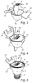
- the method may comprise the steps of providing the heat sink structure 10 having the lid portions 11, 12 and providing the electronic carrier 20, as shown in Figure 3 .
- the heat sink structure 10 may preferably be formed by deep drawing a piece of sheet metal into a cup-like shape for forming the portion of the heat sink structure 10 for accommodating the driver portion 22 of the electronic carrier 20.
- the same piece of sheet metal may also comprise the first and second lid portions 11, 12 arranged at an edge of the opening 14 of the heat sink structure 10.
- the method further comprise the steps of folding the first lid portion 11, such that it abuts the edge of, and partially close, the opening 14 of the heat sink structure 10, and subsequently arranging the light source portion 21 of the electronic carrier 20 at the first lid portion 11, as shown in Figure 4 .
- the light source portion 21 is now supported by the first lid portion 11 and the driver portion 22 extends downwards in the cavity 13 of the cup-shaped heat sink structure 10.
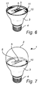
- the method may further comprise the steps of placing (or arranging) the heat sink structure 10 in the housing 3, as shown in Figure 5 , and folding the second lid portion 12 such that it substantially closes the opening 14 of the heat sink structure 10 and clamps the light source portion 21 to the first lid portion 11, as shown in Figure 6 .
- the method may finally comprise mounting the envelope 2 to the housing 3 such that the envelope 2 encloses the light sources 5.
- the method may comprise a step of providing a reflective surface on the lid portions 11, 12, e.g. by finishing, or applying a reflecting film on, the outer surface of the lid portions 11, 12.
- the lighting device 1 itself and/or the individual parts of the lighting device 1 may have different dimensions and/or sizes than those depicted/described.
- the electronic carrier 20 may have a different shape, dimension and/or size
- the envelope 2 may have a standard bulb shape, or, substantially, any other shape, e.g. round, elongated or flat.
- the number of parts e.g. the number of lid portions 11, 12, the number of light sources 5, etc., may be different from that of depicted/described devices.
Landscapes
- Engineering & Computer Science (AREA)
- General Engineering & Computer Science (AREA)
- Physics & Mathematics (AREA)
- Microelectronics & Electronic Packaging (AREA)
- Optics & Photonics (AREA)
- Manufacturing & Machinery (AREA)
- Non-Portable Lighting Devices Or Systems Thereof (AREA)
- Arrangement Of Elements, Cooling, Sealing, Or The Like Of Lighting Devices (AREA)
- Fastening Of Light Sources Or Lamp Holders (AREA)
- Led Device Packages (AREA)
Claims (14)
- Dispositif d'éclairage (1) comprenant :- une source de lumière (5) ;- un support électronique (20) comprenant une première partie (21) pour supporter la source de lumière et une seconde partie (22) pour fournir une connexion électrique à la source de lumière ; et- une structure de puits thermique (10) agencée pour une dissipation de chaleur depuis le support électronique et définissant une cavité (13), la structure de puits thermique comprenant une première partie couvercle (11) et une seconde partie couvercle (12) agencées au niveau d'une ouverture (14) de la structure de puits thermique, dans lequel la première partie couvercle (11) et la seconde partie couvercle (12) forment un couvercle sur la cavité (13) et ferment sensiblement l'ouverture (14) dans une position pliée,dans lequel la première partie du support électronique est supportée par la première partie couvercle (11) à l'extérieur de la cavité (13), et la seconde partie du support électronique est au moins partiellement enfermée par la structure de puits thermique à l'intérieur de la cavité (13) caractérisé en ce que la première et la seconde partie couvercle (11, 12) dans la position pliée définissent un trou (17) à travers lequel trou (17) s'étend le support électronique (20), et en ce que
la seconde partie couvercle (12) chevauche partiellement la première partie couvercle (11) et serre la première partie (21) du support électronique (20) sur la première partie couvercle (11) dans la position pliée. - Dispositif d'éclairage selon la revendication 1, dans lequel la structure de puits thermique et les première et seconde parties couvercles sont formées par un seul morceau de matériau.
- Dispositif d'éclairage selon l'une quelconque des revendications précédentes, dans lequel la structure de puits thermique et les première et seconde parties couvercles comprennent une tôle.
- Dispositif d'éclairage selon la revendication 2, dans lequel au moins l'une des première et deuxième parties couvercles est fixée dans une position pliée par un moyen de blocage.
- Dispositif d'éclairage selon l'une quelconque des revendications précédentes, comprenant en outre un boîtier (3) enfermant au moins partiellement la structure de puits thermique.
- Dispositif d'éclairage selon la revendication 5, dans lequel la forme extérieure de la structure de puits thermique est au moins partiellement conforme à la forme intérieure du boîtier.
- Dispositif d'éclairage selon l'une quelconque des revendications 5 ou 6, dans lequel le boîtier comprend un matériau électriquement isolant.
- Dispositif d'éclairage selon l'une quelconque des revendications 5, 6 ou 7, comprenant en outre une enveloppe (2) montée sur le boîtier (3) et enfermant la source de lumière (5).
- Dispositif d'éclairage selon l'une quelconque des revendications précédentes, dans lequel la première partie du support électronique crée un angle de 40° à 140°, de préférence de 60° à 120°, et idéalement de 80° à 100°, avec la seconde partie du support électronique.
- Dispositif d'éclairage selon l'une quelconque des revendications précédentes, dans lequel au moins l'une des première et seconde parties couvercles comprend une surface réfléchissante adaptée pour réfléchir la lumière provenant de la source de lumière.
- Dispositif d'éclairage selon l'une quelconque des revendications précédentes, dans lequel la structure de puits thermique est cupuliforme avec une autre ouverture, qui est opposée à l'ouverture (14) au niveau de laquelle les première et seconde parties couvercles sont agencées.
- Procédé de fabrication d'un dispositif d'éclairage, le procédé comprenant :- la fourniture d'une structure de puits thermique (10) définissant une cavité (13) et comprenant une première partie couvercle (11) et une seconde partie couvercle (12) agencées au niveau d'une ouverture (14) de la structure de puits thermique ;- le pliage de la première partie couvercle de telle sorte qu'elle ferme partiellement l'ouverture ;- l'agencement d'un support électronique (20) comprenant une première partie (21) pour supporter une source de lumière (5) et une seconde partie (22) pour fournir une connexion électrique à la source de lumière, de telle sorte que le support électronique (20) s'étend à travers un trou (17) défini par la première et la seconde partie couvercle (11, 12) et de telle sorte que la première partie du support électronique est supportée par la première partie couvercle à l'extérieur de la cavité (13) et la seconde partie du support électronique est au moins partiellement enfermée par la structure de puits thermique à l'intérieur de la cavité (13) ; et- le pliage de la seconde partie couvercle de telle sorte qu'elle forme, avec la première partie couvercle, un couvercle sur la cavité (13) et ferme sensiblement l'ouverture (14) de la structure de puits thermique et dans lequel la seconde partie couvercle (12) chevauche partiellement la première partie couvercle (11) et serre la première partie (21) du support électronique (20) sur la première partie couvercle (11).
- Procédé selon la revendication 12, dans lequel la structure de puits thermique (10) est formée par l'emboutissage profond d'un morceau de tôle selon une forme cupuliforme.
- Procédé selon la revendication 13, dans lequel le morceau de tôle comprend également la première partie couvercle (11) et la seconde partie couvercle (12) agencées au niveau d'un bord de l'ouverture (14) de la structure de puits thermique (10).
Applications Claiming Priority (2)
| Application Number | Priority Date | Filing Date | Title |
|---|---|---|---|
| US201261680324P | 2012-08-07 | 2012-08-07 | |
| PCT/IB2013/056461 WO2014024147A1 (fr) | 2012-08-07 | 2013-08-07 | Dispositif d'éclairage comprenant une structure de puits thermique |
Publications (2)
| Publication Number | Publication Date |
|---|---|
| EP2882998A1 EP2882998A1 (fr) | 2015-06-17 |
| EP2882998B1 true EP2882998B1 (fr) | 2016-10-12 |
Family
ID=49513977
Family Applications (1)
| Application Number | Title | Priority Date | Filing Date |
|---|---|---|---|
| EP13783986.6A Not-in-force EP2882998B1 (fr) | 2012-08-07 | 2013-08-07 | Dispositif d'éclairage avec une structure de dissipation de chaleur |
Country Status (6)
| Country | Link |
|---|---|
| US (1) | US9593838B2 (fr) |
| EP (1) | EP2882998B1 (fr) |
| JP (1) | JP6157022B2 (fr) |
| CN (1) | CN104520640B (fr) |
| RU (1) | RU2628658C2 (fr) |
| WO (1) | WO2014024147A1 (fr) |
Families Citing this family (2)
| Publication number | Priority date | Publication date | Assignee | Title |
|---|---|---|---|---|
| JP7405755B2 (ja) * | 2018-02-12 | 2023-12-26 | シグニファイ ホールディング ビー ヴィ | 発光要素用の基板を備える照明構成 |
| JP7312911B2 (ja) * | 2019-11-01 | 2023-07-21 | シグニファイ ホールディング ビー ヴィ | ヒートシンク機能を備える、曲げることが可能なpcb |
Family Cites Families (21)
| Publication number | Priority date | Publication date | Assignee | Title |
|---|---|---|---|---|
| CN1464953A (zh) * | 2001-08-09 | 2003-12-31 | 松下电器产业株式会社 | Led照明装置和卡型led照明光源 |
| JP4041411B2 (ja) * | 2003-02-07 | 2008-01-30 | 松下電器産業株式会社 | カード型led光源用回動ソケット |
| US7344296B2 (en) * | 2003-02-07 | 2008-03-18 | Matsushita Electric Industrial Co., Ltd. | Socket for led light source and lighting system using the socket |
| US6999318B2 (en) * | 2003-07-28 | 2006-02-14 | Honeywell International Inc. | Heatsinking electronic devices |
| JP2006310057A (ja) * | 2005-04-27 | 2006-11-09 | Arumo Technos Kk | Led照明灯及びled点灯制御回路 |
| KR101063446B1 (ko) * | 2006-05-30 | 2011-09-08 | 네오벌브 테크놀러지스 인크 | 높은 출력 및 높은 열발산 효율을 갖는 발광 다이오드 조명장비 |
| US8113687B2 (en) * | 2006-06-29 | 2012-02-14 | Cree, Inc. | Modular LED lighting fixture |
| CN101487583B (zh) * | 2008-01-16 | 2010-09-29 | 富士迈半导体精密工业(上海)有限公司 | 照明装置 |
| US8894238B2 (en) | 2009-05-28 | 2014-11-25 | Koninklijke Philips N.V. | Ceramic illumination device |
| US7932532B2 (en) * | 2009-08-04 | 2011-04-26 | Cree, Inc. | Solid state lighting device with improved heatsink |
| JP5601512B2 (ja) * | 2009-09-14 | 2014-10-08 | 東芝ライテック株式会社 | 発光装置および照明装置 |
| US9080755B2 (en) | 2009-10-09 | 2015-07-14 | Aps Japan Co., Ltd. | Lighting device |
| US8154179B2 (en) | 2009-12-09 | 2012-04-10 | Tsan-Chi Chen | Light emitting diode lamp having replaceable light source module |
| KR100970747B1 (ko) * | 2009-12-24 | 2010-07-16 | 쎄딕(주) | 절곡형 방열부재 |
| JP4917697B2 (ja) * | 2010-04-30 | 2012-04-18 | パナソニック株式会社 | ランプ及び照明装置 |
| JP2013541164A (ja) * | 2010-10-08 | 2013-11-07 | ソラア インコーポレーテッド | 高輝度光源 |
| EP2450613B1 (fr) * | 2010-11-08 | 2015-01-28 | LG Innotek Co., Ltd. | Dispositif d'éclairage |
| JP5190105B2 (ja) * | 2010-12-17 | 2013-04-24 | 株式会社エル光源 | Ledランプ |
| FR2970546A1 (fr) * | 2011-01-13 | 2012-07-20 | Homelights | Ampoule a diode avec isolation |
| WO2012098476A1 (fr) * | 2011-01-20 | 2012-07-26 | Koninklijke Philips Electronics N.V. | Dissipateur thermique multifonctionnel pour produits d'éclairage |
| WO2012099251A1 (fr) * | 2011-01-21 | 2012-07-26 | シチズン電子株式会社 | Procédé de fabrication pour dispositif d'éclairage et dispositif de support |
-
2013
- 2013-08-07 RU RU2015107795A patent/RU2628658C2/ru active
- 2013-08-07 US US14/419,321 patent/US9593838B2/en active Active
- 2013-08-07 WO PCT/IB2013/056461 patent/WO2014024147A1/fr active Application Filing
- 2013-08-07 CN CN201380042055.2A patent/CN104520640B/zh not_active Expired - Fee Related
- 2013-08-07 JP JP2015525997A patent/JP6157022B2/ja not_active Expired - Fee Related
- 2013-08-07 EP EP13783986.6A patent/EP2882998B1/fr not_active Not-in-force
Also Published As
| Publication number | Publication date |
|---|---|
| CN104520640B (zh) | 2018-03-23 |
| JP2015529948A (ja) | 2015-10-08 |
| US9593838B2 (en) | 2017-03-14 |
| CN104520640A (zh) | 2015-04-15 |
| EP2882998A1 (fr) | 2015-06-17 |
| RU2628658C2 (ru) | 2017-08-21 |
| US20150192287A1 (en) | 2015-07-09 |
| WO2014024147A1 (fr) | 2014-02-13 |
| JP6157022B2 (ja) | 2017-07-05 |
| RU2015107795A (ru) | 2016-09-27 |
Similar Documents
| Publication | Publication Date | Title |
|---|---|---|
| EP1914470B1 (fr) | Lampe à semi-conducteur | |
| US8231254B2 (en) | Lighting unit for vehicle headlights and vehicle headlight | |
| EP2228587B1 (fr) | Ampoule à diodes électroluminescentes et appareil d'éclairage | |
| EP2455651B1 (fr) | Unité de lampe et dispositif d'éclairage | |
| WO2012099251A1 (fr) | Procédé de fabrication pour dispositif d'éclairage et dispositif de support | |
| EP2723153A2 (fr) | Unité électronique | |
| EP2455655A2 (fr) | Unité de lampe et accessoire d'éclairage | |
| US20130020941A1 (en) | Semiconductor Lamp | |
| US20120306366A1 (en) | Bulb-type lamp and luminaire using bulb-type lamp | |
| JP5622465B2 (ja) | Led電球およびled電球の製造方法 | |
| US20140217880A1 (en) | Lamp Device, Light-Emitting Device and Luminaire | |
| JP2015220034A (ja) | Ledモジュール及びこれを備えた車両用灯具 | |
| EP2642196A1 (fr) | Luminaire et méthode de radiation thermique du luminaire | |
| US20140146553A1 (en) | Lighting module for a vehicle lighting device with semiconductor light source | |
| EP2882998B1 (fr) | Dispositif d'éclairage avec une structure de dissipation de chaleur | |
| JP5768966B2 (ja) | ランプ装置および照明器具 | |
| US9845944B2 (en) | Electronic device, LED lamp and method of manufacturing | |
| JP2014531714A (ja) | 回路基板取付器具を備えた照明デバイス | |
| JP2011171160A (ja) | Ledランプ装置およびled照明装置 | |
| JP5657319B2 (ja) | 発光装置及びこの発光装置を備えた照明器具 | |
| JP2011210380A (ja) | 照明装置 | |
| US11158777B2 (en) | LED light source | |
| JP4637268B1 (ja) | 電球型ランプ | |
| JP6226130B2 (ja) | ランプ装置および照明装置 | |
| US10322665B2 (en) | Holding device for lamps in vehicle lights having a plate-like section with receptacle providing space for different types of lamps and vehicle light |
Legal Events
| Date | Code | Title | Description |
|---|---|---|---|
| PUAI | Public reference made under article 153(3) epc to a published international application that has entered the european phase |
Free format text: ORIGINAL CODE: 0009012 |
|
| 17P | Request for examination filed |
Effective date: 20150309 |
|
| AK | Designated contracting states |
Kind code of ref document: A1 Designated state(s): AL AT BE BG CH CY CZ DE DK EE ES FI FR GB GR HR HU IE IS IT LI LT LU LV MC MK MT NL NO PL PT RO RS SE SI SK SM TR |
|
| AX | Request for extension of the european patent |
Extension state: BA ME |
|
| DAX | Request for extension of the european patent (deleted) | ||
| GRAP | Despatch of communication of intention to grant a patent |
Free format text: ORIGINAL CODE: EPIDOSNIGR1 |
|
| RIC1 | Information provided on ipc code assigned before grant |
Ipc: F21K 99/00 20160101ALI20160408BHEP Ipc: F21V 15/01 20060101ALI20160408BHEP Ipc: F21V 7/22 20060101ALI20160408BHEP Ipc: F21V 29/70 20150101ALI20160408BHEP Ipc: F21V 29/00 20150101AFI20160408BHEP Ipc: F21V 19/00 20060101ALI20160408BHEP |
|
| INTG | Intention to grant announced |
Effective date: 20160502 |
|
| RIC1 | Information provided on ipc code assigned before grant |
Ipc: F21V 19/00 20060101ALI20160419BHEP Ipc: F21V 29/507 20150101ALN20160419BHEP Ipc: F21K 9/232 20160101ALI20160419BHEP Ipc: F21Y 115/10 20160101ALN20160419BHEP Ipc: F21V 7/22 20060101ALI20160419BHEP Ipc: F21V 29/89 20150101ALN20160419BHEP Ipc: F21V 15/01 20060101ALI20160419BHEP Ipc: F21V 29/70 20150101ALI20160419BHEP Ipc: F21V 29/00 20150101AFI20160419BHEP |
|
| INTG | Intention to grant announced |
Effective date: 20160506 |
|
| GRAS | Grant fee paid |
Free format text: ORIGINAL CODE: EPIDOSNIGR3 |
|
| RAP1 | Party data changed (applicant data changed or rights of an application transferred) |
Owner name: PHILIPS LIGHTING HOLDING B.V. |
|
| GRAA | (expected) grant |
Free format text: ORIGINAL CODE: 0009210 |
|
| AK | Designated contracting states |
Kind code of ref document: B1 Designated state(s): AL AT BE BG CH CY CZ DE DK EE ES FI FR GB GR HR HU IE IS IT LI LT LU LV MC MK MT NL NO PL PT RO RS SE SI SK SM TR |
|
| REG | Reference to a national code |
Ref country code: GB Ref legal event code: FG4D |
|
| REG | Reference to a national code |
Ref country code: CH Ref legal event code: EP |
|
| REG | Reference to a national code |
Ref country code: AT Ref legal event code: REF Ref document number: 836861 Country of ref document: AT Kind code of ref document: T Effective date: 20161015 |
|
| REG | Reference to a national code |
Ref country code: IE Ref legal event code: FG4D |
|
| REG | Reference to a national code |
Ref country code: DE Ref legal event code: R096 Ref document number: 602013012787 Country of ref document: DE |
|
| REG | Reference to a national code |
Ref country code: LT Ref legal event code: MG4D |
|
| REG | Reference to a national code |
Ref country code: NL Ref legal event code: MP Effective date: 20161012 |
|
| PG25 | Lapsed in a contracting state [announced via postgrant information from national office to epo] |
Ref country code: LV Free format text: LAPSE BECAUSE OF FAILURE TO SUBMIT A TRANSLATION OF THE DESCRIPTION OR TO PAY THE FEE WITHIN THE PRESCRIBED TIME-LIMIT Effective date: 20161012 |
|
| REG | Reference to a national code |
Ref country code: AT Ref legal event code: MK05 Ref document number: 836861 Country of ref document: AT Kind code of ref document: T Effective date: 20161012 |
|
| PG25 | Lapsed in a contracting state [announced via postgrant information from national office to epo] |
Ref country code: SE Free format text: LAPSE BECAUSE OF FAILURE TO SUBMIT A TRANSLATION OF THE DESCRIPTION OR TO PAY THE FEE WITHIN THE PRESCRIBED TIME-LIMIT Effective date: 20161012 Ref country code: NO Free format text: LAPSE BECAUSE OF FAILURE TO SUBMIT A TRANSLATION OF THE DESCRIPTION OR TO PAY THE FEE WITHIN THE PRESCRIBED TIME-LIMIT Effective date: 20170112 Ref country code: GR Free format text: LAPSE BECAUSE OF FAILURE TO SUBMIT A TRANSLATION OF THE DESCRIPTION OR TO PAY THE FEE WITHIN THE PRESCRIBED TIME-LIMIT Effective date: 20170113 Ref country code: LT Free format text: LAPSE BECAUSE OF FAILURE TO SUBMIT A TRANSLATION OF THE DESCRIPTION OR TO PAY THE FEE WITHIN THE PRESCRIBED TIME-LIMIT Effective date: 20161012 |
|
| PG25 | Lapsed in a contracting state [announced via postgrant information from national office to epo] |
Ref country code: PT Free format text: LAPSE BECAUSE OF FAILURE TO SUBMIT A TRANSLATION OF THE DESCRIPTION OR TO PAY THE FEE WITHIN THE PRESCRIBED TIME-LIMIT Effective date: 20170213 Ref country code: IS Free format text: LAPSE BECAUSE OF FAILURE TO SUBMIT A TRANSLATION OF THE DESCRIPTION OR TO PAY THE FEE WITHIN THE PRESCRIBED TIME-LIMIT Effective date: 20170212 Ref country code: BE Free format text: LAPSE BECAUSE OF FAILURE TO SUBMIT A TRANSLATION OF THE DESCRIPTION OR TO PAY THE FEE WITHIN THE PRESCRIBED TIME-LIMIT Effective date: 20161012 Ref country code: FI Free format text: LAPSE BECAUSE OF FAILURE TO SUBMIT A TRANSLATION OF THE DESCRIPTION OR TO PAY THE FEE WITHIN THE PRESCRIBED TIME-LIMIT Effective date: 20161012 Ref country code: HR Free format text: LAPSE BECAUSE OF FAILURE TO SUBMIT A TRANSLATION OF THE DESCRIPTION OR TO PAY THE FEE WITHIN THE PRESCRIBED TIME-LIMIT Effective date: 20161012 Ref country code: PL Free format text: LAPSE BECAUSE OF FAILURE TO SUBMIT A TRANSLATION OF THE DESCRIPTION OR TO PAY THE FEE WITHIN THE PRESCRIBED TIME-LIMIT Effective date: 20161012 Ref country code: RS Free format text: LAPSE BECAUSE OF FAILURE TO SUBMIT A TRANSLATION OF THE DESCRIPTION OR TO PAY THE FEE WITHIN THE PRESCRIBED TIME-LIMIT Effective date: 20161012 Ref country code: NL Free format text: LAPSE BECAUSE OF FAILURE TO SUBMIT A TRANSLATION OF THE DESCRIPTION OR TO PAY THE FEE WITHIN THE PRESCRIBED TIME-LIMIT Effective date: 20161012 Ref country code: ES Free format text: LAPSE BECAUSE OF FAILURE TO SUBMIT A TRANSLATION OF THE DESCRIPTION OR TO PAY THE FEE WITHIN THE PRESCRIBED TIME-LIMIT Effective date: 20161012 Ref country code: AT Free format text: LAPSE BECAUSE OF FAILURE TO SUBMIT A TRANSLATION OF THE DESCRIPTION OR TO PAY THE FEE WITHIN THE PRESCRIBED TIME-LIMIT Effective date: 20161012 |
|
| REG | Reference to a national code |
Ref country code: DE Ref legal event code: R097 Ref document number: 602013012787 Country of ref document: DE |
|
| PG25 | Lapsed in a contracting state [announced via postgrant information from national office to epo] |
Ref country code: DK Free format text: LAPSE BECAUSE OF FAILURE TO SUBMIT A TRANSLATION OF THE DESCRIPTION OR TO PAY THE FEE WITHIN THE PRESCRIBED TIME-LIMIT Effective date: 20161012 Ref country code: EE Free format text: LAPSE BECAUSE OF FAILURE TO SUBMIT A TRANSLATION OF THE DESCRIPTION OR TO PAY THE FEE WITHIN THE PRESCRIBED TIME-LIMIT Effective date: 20161012 Ref country code: CZ Free format text: LAPSE BECAUSE OF FAILURE TO SUBMIT A TRANSLATION OF THE DESCRIPTION OR TO PAY THE FEE WITHIN THE PRESCRIBED TIME-LIMIT Effective date: 20161012 Ref country code: RO Free format text: LAPSE BECAUSE OF FAILURE TO SUBMIT A TRANSLATION OF THE DESCRIPTION OR TO PAY THE FEE WITHIN THE PRESCRIBED TIME-LIMIT Effective date: 20161012 Ref country code: SK Free format text: LAPSE BECAUSE OF FAILURE TO SUBMIT A TRANSLATION OF THE DESCRIPTION OR TO PAY THE FEE WITHIN THE PRESCRIBED TIME-LIMIT Effective date: 20161012 |
|
| RIN2 | Information on inventor provided after grant (corrected) |
Inventor name: VAN ES, ARTHUR, ROBERT Inventor name: BUKKEMS, PETER, JOHANNES, MARTINUS |
|
| PLBE | No opposition filed within time limit |
Free format text: ORIGINAL CODE: 0009261 |
|
| STAA | Information on the status of an ep patent application or granted ep patent |
Free format text: STATUS: NO OPPOSITION FILED WITHIN TIME LIMIT |
|
| REG | Reference to a national code |
Ref country code: FR Ref legal event code: PLFP Year of fee payment: 5 |
|
| PG25 | Lapsed in a contracting state [announced via postgrant information from national office to epo] |
Ref country code: BG Free format text: LAPSE BECAUSE OF FAILURE TO SUBMIT A TRANSLATION OF THE DESCRIPTION OR TO PAY THE FEE WITHIN THE PRESCRIBED TIME-LIMIT Effective date: 20170112 Ref country code: SM Free format text: LAPSE BECAUSE OF FAILURE TO SUBMIT A TRANSLATION OF THE DESCRIPTION OR TO PAY THE FEE WITHIN THE PRESCRIBED TIME-LIMIT Effective date: 20161012 Ref country code: IT Free format text: LAPSE BECAUSE OF FAILURE TO SUBMIT A TRANSLATION OF THE DESCRIPTION OR TO PAY THE FEE WITHIN THE PRESCRIBED TIME-LIMIT Effective date: 20161012 |
|
| 26N | No opposition filed |
Effective date: 20170713 |
|
| PG25 | Lapsed in a contracting state [announced via postgrant information from national office to epo] |
Ref country code: SI Free format text: LAPSE BECAUSE OF FAILURE TO SUBMIT A TRANSLATION OF THE DESCRIPTION OR TO PAY THE FEE WITHIN THE PRESCRIBED TIME-LIMIT Effective date: 20161012 |
|
| REG | Reference to a national code |
Ref country code: CH Ref legal event code: PL |
|
| PG25 | Lapsed in a contracting state [announced via postgrant information from national office to epo] |
Ref country code: MC Free format text: LAPSE BECAUSE OF FAILURE TO SUBMIT A TRANSLATION OF THE DESCRIPTION OR TO PAY THE FEE WITHIN THE PRESCRIBED TIME-LIMIT Effective date: 20161012 |
|
| PG25 | Lapsed in a contracting state [announced via postgrant information from national office to epo] |
Ref country code: LI Free format text: LAPSE BECAUSE OF NON-PAYMENT OF DUE FEES Effective date: 20170831 Ref country code: CH Free format text: LAPSE BECAUSE OF NON-PAYMENT OF DUE FEES Effective date: 20170831 |
|
| REG | Reference to a national code |
Ref country code: IE Ref legal event code: MM4A |
|
| PG25 | Lapsed in a contracting state [announced via postgrant information from national office to epo] |
Ref country code: LU Free format text: LAPSE BECAUSE OF NON-PAYMENT OF DUE FEES Effective date: 20170807 |
|
| PG25 | Lapsed in a contracting state [announced via postgrant information from national office to epo] |
Ref country code: IE Free format text: LAPSE BECAUSE OF NON-PAYMENT OF DUE FEES Effective date: 20170807 |
|
| REG | Reference to a national code |
Ref country code: FR Ref legal event code: PLFP Year of fee payment: 6 |
|
| PG25 | Lapsed in a contracting state [announced via postgrant information from national office to epo] |
Ref country code: MT Free format text: LAPSE BECAUSE OF NON-PAYMENT OF DUE FEES Effective date: 20170807 |
|
| PG25 | Lapsed in a contracting state [announced via postgrant information from national office to epo] |
Ref country code: HU Free format text: LAPSE BECAUSE OF FAILURE TO SUBMIT A TRANSLATION OF THE DESCRIPTION OR TO PAY THE FEE WITHIN THE PRESCRIBED TIME-LIMIT; INVALID AB INITIO Effective date: 20130807 |
|
| PG25 | Lapsed in a contracting state [announced via postgrant information from national office to epo] |
Ref country code: CY Free format text: LAPSE BECAUSE OF FAILURE TO SUBMIT A TRANSLATION OF THE DESCRIPTION OR TO PAY THE FEE WITHIN THE PRESCRIBED TIME-LIMIT Effective date: 20161012 |
|
| PG25 | Lapsed in a contracting state [announced via postgrant information from national office to epo] |
Ref country code: MK Free format text: LAPSE BECAUSE OF FAILURE TO SUBMIT A TRANSLATION OF THE DESCRIPTION OR TO PAY THE FEE WITHIN THE PRESCRIBED TIME-LIMIT Effective date: 20161012 |
|
| PG25 | Lapsed in a contracting state [announced via postgrant information from national office to epo] |
Ref country code: TR Free format text: LAPSE BECAUSE OF FAILURE TO SUBMIT A TRANSLATION OF THE DESCRIPTION OR TO PAY THE FEE WITHIN THE PRESCRIBED TIME-LIMIT Effective date: 20161012 |
|
| PG25 | Lapsed in a contracting state [announced via postgrant information from national office to epo] |
Ref country code: AL Free format text: LAPSE BECAUSE OF FAILURE TO SUBMIT A TRANSLATION OF THE DESCRIPTION OR TO PAY THE FEE WITHIN THE PRESCRIBED TIME-LIMIT Effective date: 20161012 |
|
| REG | Reference to a national code |
Ref country code: DE Ref legal event code: R082 Ref document number: 602013012787 Country of ref document: DE Representative=s name: MEISSNER BOLTE PATENTANWAELTE RECHTSANWAELTE P, DE Ref country code: DE Ref legal event code: R081 Ref document number: 602013012787 Country of ref document: DE Owner name: SIGNIFY HOLDING B.V., NL Free format text: FORMER OWNER: PHILIPS LIGHTING HOLDING B.V., EINDHOVEN, NL |
|
| PGFP | Annual fee paid to national office [announced via postgrant information from national office to epo] |
Ref country code: FR Payment date: 20210826 Year of fee payment: 9 |
|
| PGFP | Annual fee paid to national office [announced via postgrant information from national office to epo] |
Ref country code: GB Payment date: 20210826 Year of fee payment: 9 |
|
| PGFP | Annual fee paid to national office [announced via postgrant information from national office to epo] |
Ref country code: DE Payment date: 20211027 Year of fee payment: 9 |
|
| REG | Reference to a national code |
Ref country code: DE Ref legal event code: R119 Ref document number: 602013012787 Country of ref document: DE |
|
| GBPC | Gb: european patent ceased through non-payment of renewal fee |
Effective date: 20220807 |
|
| PG25 | Lapsed in a contracting state [announced via postgrant information from national office to epo] |
Ref country code: FR Free format text: LAPSE BECAUSE OF NON-PAYMENT OF DUE FEES Effective date: 20220831 Ref country code: DE Free format text: LAPSE BECAUSE OF NON-PAYMENT OF DUE FEES Effective date: 20230301 |
|
| PG25 | Lapsed in a contracting state [announced via postgrant information from national office to epo] |
Ref country code: GB Free format text: LAPSE BECAUSE OF NON-PAYMENT OF DUE FEES Effective date: 20220807 |