EP2882070B1 - Non-contact charger and non-contact charge system - Google Patents
Non-contact charger and non-contact charge system Download PDFInfo
- Publication number
- EP2882070B1 EP2882070B1 EP15152121.8A EP15152121A EP2882070B1 EP 2882070 B1 EP2882070 B1 EP 2882070B1 EP 15152121 A EP15152121 A EP 15152121A EP 2882070 B1 EP2882070 B1 EP 2882070B1
- Authority
- EP
- European Patent Office
- Prior art keywords
- contactless charger
- contactless
- charge
- electronic device
- load
- Prior art date
- Legal status (The legal status is an assumption and is not a legal conclusion. Google has not performed a legal analysis and makes no representation as to the accuracy of the status listed.)
- Active
Links
- 238000012546 transfer Methods 0.000 claims description 22
- 230000007704 transition Effects 0.000 description 22
- 238000010586 diagram Methods 0.000 description 20
- 238000001514 detection method Methods 0.000 description 16
- 230000001681 protective effect Effects 0.000 description 14
- 230000005540 biological transmission Effects 0.000 description 10
- 238000000034 method Methods 0.000 description 7
- 238000012545 processing Methods 0.000 description 7
- 230000004044 response Effects 0.000 description 7
- 230000008859 change Effects 0.000 description 6
- 230000010363 phase shift Effects 0.000 description 6
- 230000007423 decrease Effects 0.000 description 4
- 230000009467 reduction Effects 0.000 description 4
- 230000008901 benefit Effects 0.000 description 2
- 230000003247 decreasing effect Effects 0.000 description 2
- 239000000284 extract Substances 0.000 description 2
- 230000004048 modification Effects 0.000 description 2
- 238000012986 modification Methods 0.000 description 2
- 238000009877 rendering Methods 0.000 description 2
- 230000003252 repetitive effect Effects 0.000 description 2
- 108010076504 Protein Sorting Signals Proteins 0.000 description 1
- 230000004913 activation Effects 0.000 description 1
- 230000004075 alteration Effects 0.000 description 1
- 238000004891 communication Methods 0.000 description 1
- 230000002708 enhancing effect Effects 0.000 description 1
- VJYFKVYYMZPMAB-UHFFFAOYSA-N ethoprophos Chemical compound CCCSP(=O)(OCC)SCCC VJYFKVYYMZPMAB-UHFFFAOYSA-N 0.000 description 1
- 230000020169 heat generation Effects 0.000 description 1
- 238000010438 heat treatment Methods 0.000 description 1
- 230000001788 irregular Effects 0.000 description 1
- 239000002184 metal Substances 0.000 description 1
- 229910052751 metal Inorganic materials 0.000 description 1
- 230000035755 proliferation Effects 0.000 description 1
- 230000008054 signal transmission Effects 0.000 description 1
- 239000000126 substance Substances 0.000 description 1
Images


Classifications
-
- H—ELECTRICITY
- H01—ELECTRIC ELEMENTS
- H01M—PROCESSES OR MEANS, e.g. BATTERIES, FOR THE DIRECT CONVERSION OF CHEMICAL ENERGY INTO ELECTRICAL ENERGY
- H01M10/00—Secondary cells; Manufacture thereof
- H01M10/42—Methods or arrangements for servicing or maintenance of secondary cells or secondary half-cells
- H01M10/44—Methods for charging or discharging
-
- H—ELECTRICITY
- H02—GENERATION; CONVERSION OR DISTRIBUTION OF ELECTRIC POWER
- H02J—CIRCUIT ARRANGEMENTS OR SYSTEMS FOR SUPPLYING OR DISTRIBUTING ELECTRIC POWER; SYSTEMS FOR STORING ELECTRIC ENERGY
- H02J50/00—Circuit arrangements or systems for wireless supply or distribution of electric power
- H02J50/10—Circuit arrangements or systems for wireless supply or distribution of electric power using inductive coupling
-
- H—ELECTRICITY
- H02—GENERATION; CONVERSION OR DISTRIBUTION OF ELECTRIC POWER
- H02J—CIRCUIT ARRANGEMENTS OR SYSTEMS FOR SUPPLYING OR DISTRIBUTING ELECTRIC POWER; SYSTEMS FOR STORING ELECTRIC ENERGY
- H02J50/00—Circuit arrangements or systems for wireless supply or distribution of electric power
- H02J50/60—Circuit arrangements or systems for wireless supply or distribution of electric power responsive to the presence of foreign objects, e.g. detection of living beings
-
- H—ELECTRICITY
- H02—GENERATION; CONVERSION OR DISTRIBUTION OF ELECTRIC POWER
- H02J—CIRCUIT ARRANGEMENTS OR SYSTEMS FOR SUPPLYING OR DISTRIBUTING ELECTRIC POWER; SYSTEMS FOR STORING ELECTRIC ENERGY
- H02J50/00—Circuit arrangements or systems for wireless supply or distribution of electric power
- H02J50/80—Circuit arrangements or systems for wireless supply or distribution of electric power involving the exchange of data, concerning supply or distribution of electric power, between transmitting devices and receiving devices
-
- H—ELECTRICITY
- H01—ELECTRIC ELEMENTS
- H01M—PROCESSES OR MEANS, e.g. BATTERIES, FOR THE DIRECT CONVERSION OF CHEMICAL ENERGY INTO ELECTRICAL ENERGY
- H01M10/00—Secondary cells; Manufacture thereof
- H01M10/42—Methods or arrangements for servicing or maintenance of secondary cells or secondary half-cells
- H01M10/44—Methods for charging or discharging
- H01M10/446—Initial charging measures
-
- H—ELECTRICITY
- H01—ELECTRIC ELEMENTS
- H01M—PROCESSES OR MEANS, e.g. BATTERIES, FOR THE DIRECT CONVERSION OF CHEMICAL ENERGY INTO ELECTRICAL ENERGY
- H01M10/00—Secondary cells; Manufacture thereof
- H01M10/42—Methods or arrangements for servicing or maintenance of secondary cells or secondary half-cells
- H01M10/44—Methods for charging or discharging
- H01M10/448—End of discharge regulating measures
-
- Y—GENERAL TAGGING OF NEW TECHNOLOGICAL DEVELOPMENTS; GENERAL TAGGING OF CROSS-SECTIONAL TECHNOLOGIES SPANNING OVER SEVERAL SECTIONS OF THE IPC; TECHNICAL SUBJECTS COVERED BY FORMER USPC CROSS-REFERENCE ART COLLECTIONS [XRACs] AND DIGESTS
- Y02—TECHNOLOGIES OR APPLICATIONS FOR MITIGATION OR ADAPTATION AGAINST CLIMATE CHANGE
- Y02E—REDUCTION OF GREENHOUSE GAS [GHG] EMISSIONS, RELATED TO ENERGY GENERATION, TRANSMISSION OR DISTRIBUTION
- Y02E60/00—Enabling technologies; Technologies with a potential or indirect contribution to GHG emissions mitigation
- Y02E60/10—Energy storage using batteries
Definitions
- the present invention relates to a contactless charging system that recharges an electronic device with electric power supplied from a charger, the electronic device, a contactless charger, and a battery pack for the electronic device.
- a secondary battery that enables performance of repetitive charge-discharge operations is used in the electronic device.
- a contactless charging system that enables recharging of the secondary battery without contacting the electronic device has been conceived as a system for recharging the secondary battery.
- Patent Documents 1 and 2 describe; for instance, a mobile phone adopting a contactless charging system.
- Patent Document 3 describes a power transmission apparatus that detects a change in the phase and amplitude value of a primary (charging) voltage attributable to a change in a secondary load (an object to be recharged) and that determines whether or not the load is a regular article.
- JP 2006 141170 relates to contactless charging. If the load is present and positioned correctly it is checked as to whether the load is fully charged. After the charging is stopped, the flow diagram returns again to load checking.
- the present invention has been conceived in view of the circumstances and aims at providing a battery back, an electronic device, and a contactless recharging system that provide excellent usability, prevent power consumption, and allow for a safety measure.
- a first aspect of the present invention provides a contactless charger for charging, in a contactless manner, an electronic device using a secondary battery as a power source, the charger including a transceiving section that receives from the electronic device a full charge command indicating completion of recharge and a control section that shifts, upon receipt of the full charge command, the contactless charger to a charge stop state in which charge of the electronic device is not performed, wherein the control section generates, in a charge stop state, a load check signal for checking whether or not the electronic device is placed on the contactless charger in a rechargeable manner, and the transceiving section sends the load check signal.
- the contactless charger can determine the placement state of the electronic device and shift to an appropriate state according to a determination result.
- a second aspect of the present invention provides the contactless charger defined in claim I, wherein, when it is ascertained by the load check signal that the electronic device is placed, the control section maintains the contactless charger in a charge stop state; and, when it is ascertained by the load check signal that the electronic device is not placed, the control section shifts the contactless charger to an initial state achieved immediately after activation of a power source.
- the contactless charger can determine the placement state of the electronic device and shift to an appropriate state according to a determination result. Hence, it is possible to reduce power consumption and take a safety measure.
- a third aspect of the present invention is directed toward the contactless charger defined in claim I, wherein the control section further generates, in a charge stop state, a charge restart check command for checking whether or not the electronic device requires recharge, and the transceiving section transmits the charge restart check command.
- the contactless charger can determine the recharge state of the electronic device and shift to an appropriate state according to a determination result.
- a fourth aspect of the present invention provides the contactless charger defined in claim 3, wherein the control section intermittently generates the load check signal and the charge restart check command, and time intervals at which the charge restart check command is generated are larger than time intervals at which the load check signal is generated.
- the contactless charger can reduce the number of times a charge restart check command is transmitted, and power consumption can be reduced.
- a fifth aspect of the present invention provides the contactless charger defined in claim 4, wherein the transceiving section is made up of a coil that transmits power for recharging the electronic device; and the contactless charger further includes a modulation section that superimposes the load check signal and the charge restart check command on power and that modulates the power.
- the contactless charger can readily transmit a command.
- a sixth aspect of the present invention provides the contactless charger defined in claim 3, wherein the transceiving section is made up of a coil that transmits power for recharging the electronic device; and the control section determines, from a phase change in an electric current developing in the coil, that the electronic device is placed.
- the contactless charger can readily determine the placement state of the electronic device.
- a seventh aspect of the present invention provides the contactless charger defined in claim 3, wherein, when the transceiving section receives, in response to the charge restart check command, a recharge command indicating that the electronic device requests recharge, the control section shifts the contactless charger to a power transfer state; and, when the transceiving section does not receive the recharge command in response to the charge restart check command, the control section holds the contactless charger in a charge stop state.
- the contactless charger can determine the charge state of the electronic device and shift to an appropriate state in accordance with a determination result.
- An eighth aspect of the present invention provides the contactless charger defined in claim 7, wherein the transceiving section is made up of a coil for transmitting power for charging the electronic device, and the control section determines the full charge command and the recharge command from a phase change in an electric current developing in the coil.
- the contactless charger can readily determine a command.
- a ninth aspect of the present invention provides an electronic device that uses as a power source a secondary battery which can be charged by a contactless charger for effecting charging in a contactless manner, the device comprising: a control section that generates a full charge command indicating that the contactless charger is shifted to a charge stop state in which charging of the electronic device is not performed, in response to completion of charge of the secondary battery; and a transceiving section for transmitting the full charge command to the contactless charger, wherein, when the transceiving section receives from the contactless charger, in a charge stop state, a charge restart check command for checking whether or not the electronic device requests recharge, the control section checks whether or not the secondary battery requests recharge; and, when the recharge is requested, the control section generates a recharge command indicating a request for recharge, and the transceiving section transmits the recharge command to the contactless charger.
- the electronic device can report a recharge state to the contactless charger and shift the contactless charger to an appropriate state.
- a tenth aspect of the present invention can provide the electronic device defined in claim 9, wherein the transceiving section is made up of a coil that receives from the contactless charger power for charging the secondary battery; and the electronic device further includes a modulation section that superimposes the full charge command and the recharge command on an electric current generated by the electronic device and that modulates the electric current.
- the contactless charger can readily transmit a command.
- An eleventh aspect of the present invention provides the electronic device defined in claim 10, wherein the modulation section differentiates the full charge command and the recharge command in terms of a difference in data sequence.
- the contactless charger can readily transmit a different command.
- a twelfth aspect of the present invention provides a battery pack attachable to an electronic device that uses, as a power source, a secondary battery which can be charged by a contactless charger for effecting charge in a contactless fashion, wherein the electronic device has a control section that generates, in response to completion of charge of the secondary battery, a full charge command indicating that the contactless charger is shifted to a charge stop state in which the electronic device is not charged; and the battery pack has the secondary battery, a protective circuit for protecting the secondary battery, and a coil for transmitting the full charge command to the contactless charger.
- a thirteenth aspect of the present invention provides a battery pack attachable to an electronic device that uses, as a power source, a secondary battery which can be charged by a contactless charger for effecting charge in a contactless fashion, the pack comprising: the secondary battery; a control section that generates, in response to completion of charge of the secondary battery, a full charge command indicating that the contactless charger is shifted to a charge stop state in which the electronic device is not charged; and a transceiving section that transmits the full charge command to the contactless charger.
- the twelfth and thirteenth battery packs are objects that are independently traded separately from a mobile phone or an electronic device.
- a fourteenth aspect of the present invention provides an electronic device that allows attachment of the battery pack defined in claim 13.
- a fifteenth aspect of the present invention provides a contactless charging system including an electronic device and a contactless charger for charging the electronic device in a contactless fashion, wherein a full charge command indicating that charge of the electronic device is completed is transmitted; the contactless charger shifts to a charge stop state in which charge of the electronic device is not performed, upon receipt of the full charge command; the contactless charger generates, in a charge stop state, a load check signal for checking whether or not the electronic device is placed on the contactless charger in a state where the electronic device can be recharged, and transmits the load check signal; and the contactless charger further generates, in a charge stop state, a charge restart check command for checking whether or not the electronic device requests recharge, and transmits the command.
- the contactless charging system enables a reduction in power consumed by the contactless charger after completion of charge, and can also incorporate a safety measure for preventing generation of heat, which would otherwise be caused after completion of charge. Further, recharge is voluntarily performed at the time of a decrease in the voltage of a secondary battery; hence, usability of the contactless charging system can be further enhanced.
- a battery pack, an electronic device, a contactless charger, and a contactless charging system of embodiments of the present invention will be described hereinbelow by reference to the drawings.
- a mobile phone is described as an example of the electronic device.
- the electronic device of the present invention includes various electronic devices that use, as a power source, a secondary battery which can be repeatedly utilized by recharge, such as a portable information terminal (PDA: Personal Digital Assistant).
- PDA Personal Digital Assistant
- Fig. 1 is a block diagram for describing an overview of a contactless charging system of a first embodiment of the present invention.
- the contactless charging system of the present embodiment is made up of a mobile phone 100, a contactless charger 200, and an AC adaptor 300.
- the mobile phone 100 is supplied with electric power while remaining out of contact with the contactless charger 200 and can recharge a battery cell (a secondary battery) 160 to be described later.
- the term "contactless" means that the mobile phone 100 and the contactless charger 200 can exchange electric power (an electric wave), a signal, and the like, while they are not in direct, electrical conduction with each other by way of their metal terminals.
- the mobile phone 100 has a main control section 110, an alarm section driver circuit 120, an alarm section 130, a charging circuit 140, a protective circuit 150, a battery cell 160, and a contactless charging circuit 170.
- the main control section 110 controls overall operation of the mobile phone 100; is made up of various arithmetic processing circuits that operate in accordance with predetermined programs; monitors a state of the charging circuit 140; and controls the alarm section driver circuit 120.
- Electric power from the contactless charging circuit 170 is input to the charging circuit 140 and controls charging of the battery cell 160 by way of the protective circuit 150. Further, the charging circuit 140 reports a charge status of the battery cell 160, or the like, to the main control section 110.
- the protective circuit 150 supplies the battery cell 160 with the electric power received from the charging circuit 140, thereby charging the battery cell. Further, the protective circuit 150 has a temperature sensor and an overcurrent sensor and monitors the state of charge of the battery cell 160. When having determined occurrence of an anomaly by detecting a high temperature or an overcurrent, the protective circuit stops charge of the battery cell 160, thereby protecting the battery cell 160. An anomaly detection signal achieved at the time of detection of an anomaly is output to the main control section 110 by way of the charging circuit 140 and sent to the user by way of the alarm section 130.
- the battery cell 160 functions as an example secondary battery that can be recharged by way of the protective circuit 150 and undergo repetitive charges and discharges.
- the alarm section driver circuit 120 is a circuit that drives the alarm section 130 under control of the main control section 110.
- the alarm section 130 is a section that sends a predetermined alarm signal to the user by a drive signal of the alarm section driver circuit 120 and that is made up of a buzzer, a vibrator, and a light-emitting section, such as an LED (light-emitting diode).
- the contactless charging circuit 170 has a control section 171, an authentication section 172, a modulation section 173, a demodulation section 174, a switching circuit 175, a rectifying circuit 176, and a coil 177, and serves as a principal section that performs operation for effecting contactless charge of the mobile phone 100.
- the contactless charging circuit 170 can be configured so as to be readily removed, as a single module, from a main unit of the mobile phone 100.
- the coil 177 works as a secondary coil that is electromagnetically coupled to a coil 280 provided in a contactless charger 200, to thus be supplied with electric power, and outputs supplied AC power to the rectifying circuit 176 and the demodulation section 174. Moreover, the coil 177 is electromagnetically coupled to the coil 280, thereby transmitting a command.
- the rectifying circuit 176 converts AC power output from the coil 177 into DC power and output the DC power to the switching circuit 175 and the modulation section 173.
- the switching circuit 175 switches whether (ON) or not (OFF) to output the DC power output from the rectifying circuit 176 to the charging circuit 140. Switching is performed in accordance with a command from the control section 171 as will be described later.
- the demodulation section 174 receives AC power from the coil 177 supplied with the AC power from the coil 280 of the contactless charger 200. As will be described later, an AC wave of the AC power serves as a carrier wave (carrier) for carrying a digital signal, and the demodulation section 174 extracts and decodes the digital signal and outputs the thus-decoded signal to the authentication section 172.
- carrier wave carrier wave
- the authentication section 172 establishes communication with the contactless charger 200 by way of the coil 177, and determines and authenticates a command responsive to the digital signal included in electric power supplied from the contactless charger 200. A result of authentication is reported to the control section 171.
- the control section 171 is built from various arithmetic processing circuits that operate in accordance with predetermined programs, as is the main control section 110; and controls operation of the contactless charging circuit 170 and generates various commands to be described later.
- the control section 171 performs various control operations relevant to operation of the contactless charging circuit 170, such as analysis of authentication results that have been acquired by the authentication section 172 and that are responsive to various commands transmitted from the contactless charger 200, receipt of a full charge status showing that charge of the battery cell 160 performed by the charging circuit 140 is completed, and ON-OFF control of the switching circuit 175.
- the modulation section 173 transmits a digital signal corresponding to a predetermined command generated by the control section 171 to the coil 280 of the contactless charger 200 by load modulation to be described later.
- the contactless charger 200 has an alarm section 210, an alarm driver circuit 220, a control section 230, a modulation section 240, an authentication section 250, a demodulation section 260, a coil driver circuit 270, a coil 280.
- the contactless charger 200 assumes various shapes, such as a desktop-type charger and an inbuilt charger that is built in a table of an eating place like a restaurant, a bench like a park bench, a guardrail for a vehicle like a railway, a center console for an automobile or the like, and a handrail of an escalator. In general, a circuit is built and formed in a plastic housing.
- the contactless charger 200 receives a power supply from the AC power source 10 by way of an AC adaptor 300.
- the mobile phone 100 can be recharged as a result of the mobile phone 100 being placed on the contactless charger 200.
- the alarm section 210 and the alarm section driver circuit 220 are functionally equivalent to the alarm section 130 and the alarm section driver circuit 120 of the mobile phone 100.
- the control section 230 controls overall operation of the contactless charger 200 and is built from various arithmetic processing circuits that operate in accordance with predetermined programs. The control section 230 generates various commands to be described later.
- the modulation section 240 superimposes on a carrier wave a digital signal corresponding to any of various commands generated by the control section 230, and modulates the thus-superimposed signal.
- the coil driver circuit 270 drives the coil 280 for transmitting the modulated carrier wave.
- the coil 280 functions as a primary coil that is electromagnetically coupled to the coil 177 provided in the mobile phone 100, to thus transmit electric power.
- the coil 280 transmits an AC wave originating from the coil driver circuit 270 to the coil 177.
- the coil 280 is electromagnetically coupled to the coil 177, thereby outputting a command to the identification section 250 by way of the demodulation section 260.
- the coil 280 functions as a transceiving section that transmits and receives electric power and various commands and signals to be described later.
- the demodulation section 260 receives an AC current from the coil 280 that is supplied with a signal from the coil 177 of the mobile phone 100 and that generates an AC current from the signal.
- an AC wave of the AC current works as a carrier wave (a carrier) that carries a digital signal, and the demodulation section 260 extracts and decodes the digital signal and output the thus-decoded signal to the authentication section 250.
- the authentication section 250 determines and authenticates a command corresponding to the digital signal acquired by the demodulation section 260. A result of authentication is reported to the control section 230.
- the AC adaptor 300 is connected to the AC power source 10; converts AC power to DC power; and outputs the DC power to the coil driver circuit 270 by way of a power cable 310.
- the AC adaptor 300 is provided in a housing separate from the contactless charger 300; however, the AC adaptor 300 may also be provided in the contactless charger 200 as one circuit.
- electric power is supplied from the contactless charger 200 to the mobile phone 100 along the following path.
- various commands are exchanged between the mobile phone 100 and the contactless charger 200 by a digital signal.
- a full charge command indicating completion of charge of the battery cell 160 of the mobile phone 100 is transmitted, as one of such commands, from the mobile phone 100 to the contactless charger 200 along the following path.
- the charging circuit 140 ⁇ the control section 171 ⁇ the authentication section 172 ⁇ the modulation section 173 ⁇ the rectifying circuit 176 ⁇ the coil 177 ⁇ the coil 280 ⁇ the demodulation section 260 ⁇ the authentication section 250 ⁇ the control section 230
- power and a command are transmitted by way of the rectifying circuit 176 and the coil 280 that are common transmission channels.
- an AC wave of AC power to be transmitted is taken as a carrier wave; a command stemming from a digital signal is superimposed on the carrier wave; and the carrier wave is transmitted.
- the electric power is transmitted from the contactless charger 200 to the mobile phone 100 but not transmitted from the mobile phone 100 to the contactless charger 200.
- Fig. 2 shows, though described also in connection with Patent Document 3, a method for determining whether or not an object is placed on the contactless charger 200 and whether or not the object placed on the charger is the mobile phone 100; namely, the status of an object to be charged.
- the control section 230 of the contactless charger 200 generates at the time of determination a load check signal for checking presence or absence of a load, and AC power is sent from the coil 280 through modulation effected by the modulation section 240.
- (a) of Fig. 2 shows a voltage (a sinusoidal waveform) developing in the coil 280.
- the contactless charger 200 can detect whether or not the mobile phone 100 is placed in accordance with such a change in current phase.
- phase shift assumes A+ ⁇ (see a conceptual rendering (d2)).
- settings are made so as to correspond to "1" of the digital signal.
- Various combinations of "0" and “1” signals can be generated by varying the modulation load in time series, so that a plurality of types of digital signal sequences to be transmitted can be generated.
- transmission of various commands a full charge command and a recharge command which will be described later, and the like
- PSK Phase Shift Keying
- the AC current from the coil 280 causes a phase shift B, as shown in (e) of Fig. 2 .
- the contactless charger 200 can determine from the phase shift that the placed substance is not the mobile phone 100.
- a plurality of commands (a load check signal, a charge restart check command, and the like, which will be described later) can be transmitted by use of FSK (Frequency Shift Keying).
- FSK Frequency Shift Keying
- the demodulation section 174 demodulates the commands.
- modulation scheme is illustrative, and no particular limitations are imposed on the scheme, so long as the scheme enables ascertainment of presence/absence of load and determination of a command.
- Fig. 3 is a state transition diagram showing the state transition of the contactless charger 200 of the present embodiment.
- the control section 230 shifts the contactless charger 200 to a standby mode corresponding to an initial state (S1).
- the control section 230 checks presence or absence of load in accordance with the scheme shown in Fig. 2 .
- the control section 230 generates a load check signal for checking presence or absence of load, and AC power is transmitted from the coil 280 through modulation performed by the modulation section 240.
- the control section 230 maintains the contactless charger 200 in a standby mode.
- the control section 230 shifts the contactless charger 200 to an authentication mode (S2).
- the control section 230 generates an authentication request command for requesting to perform authentication, and the command is transmitted from the coil 280 through modulation performed by the modulation section 240.
- the authentication section 250 authenticates and determines the demodulated digital signal, thereby determining whether or not an authentication ID of the mobile phone 100 can be acquired.
- the control section 230 brings the contactless charger 200 into an error mode (S3).
- the control section 230 again checks whether or not there is load, in accordance with the scheme shown in Fig. 2 .
- the contactless charger 200 is again brought into a standby mode (S 1).
- S3 When load is determined to be present (T15), an error mode is maintained (S3).
- the control section 230 shifts the contactless charger 200 to a transfer mode (in course of recharge) (S4).
- the authentication section 250 authenticates and determines the demodulated digital signal, thereby determining whether or not the signal is a full charge command indicating completion of recharge of the battery cell 160 of the mobile phone 100. Further, in accordance with the scheme shown in Fig. 2 , the authentication section 250 also determines whether load is normal or extraneous and checks load. On the basis of determination results, the control section 230 shifts the mode of the contactless charger 200 as follows.
- the control section 230 again shifts the contactless charger 200 to the standby mode (S1).
- the control section 230 shifts the contactless charger 200 to an error mode (S3).
- the contactless charger still remains in recharge, and hence the control section 230 maintains the contactless charger 200 in the transfer mode (S4).
- the control section 230 shifts the contactless charger 200 to a recharge completion mode corresponding to a charge stop state in order to complete charging operation (S5).
- the control section 230 holds the contactless charger 200 in the recharge completion mode (T12).
- the control section 230 again shifts the contactless charger 200 to the standby mode (S1).
- Fig. 4 is a state transition diagram showing the state transition of the mobile phone 100 of the embodiment. First, power is not supplied from the contactless charger 200, and the power source of the contactless charging circuit 170 is turned off and brought into an initial state (S21).
- the contactless charging circuit 170 is activated (S22).
- the control section 171 maintains the state of the contactless charging circuit 170 achieved at startup.
- the control section 171 shifts the mobile phone 100 (the contactless charging circuit 170) to the authentication mode (S23).
- the control section 171 authenticates the contactless charger 200.
- the control section 171 transmits a recharge completion report; i.e., a full charge command, to the contactless charging circuit 200 by way of the authentication section 172, the modulation section 173, the rectifying circuit 176, and the coil 177 (S25). Since the power supply from the coil 280 is stopped after transmission of the command, the contactless charging circuit 170 is deactivated (T30) and again shifts to the power-off state (S21).
- Fig. 5 is a sequence diagram for describing exchange of signals (an authentication ID and commands) between the contactless charger 200 and the mobile phone 100 of the present embodiment.
- a load check signal is transmitted at predetermined time intervals from the contactless charger 200 to the mobile phone 100.
- the contactless charger 200 detects the mobile phone 100 in accordance with the scheme shown in Fig. 2 .
- an authentication request code is transmitted from the contactless charger 200 to the mobile phone 100, and an authentication ID is transmitted as an answer signal from the mobile phone 100 to the contactless charger 200.
- a transfer mode (S4 in Fig. 3 ) a regular load command indicating that load is regular is transmitted at predetermined time intervals from the mobile phone 100 to the contactless charger 200, and transmission of power from the contactless charger 200 to the mobile phone 100 is maintained.
- the full charge command is transmitted from the mobile phone 100 to the contactless charger 200, whereupon power transmission is stopped.
- the load check signal is transmitted at predetermined time intervals from the contactless charger 200 to the mobile phone 100. For instance, when the mobile phone 100 is disconnected from the contactless charger 200, the contactless charger 200 detects absence of the mobile phone 100 in accordance with the scheme shown in Fig. 2 , thereby again shifting to the standby mode.
- the error mode (S3 in Fig. 3 ) is not shown in Fig. 5 .
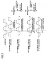
- Fig. 6 is a view conceptually showing operation timings of the contactless charger 200 in the form of H or L.
- An H period represents that the charger 200 is in operation (any of operation for transferring a load check signal and checking load, authentication operation, and power transmission operation), and an L period represents that signal transfer and power transfer operation are stopped.
- respective modes namely, a standby mode (a); an authentication mode (b); a transfer mode (c); a charge completion mode (d); and an error mode (e)
- transfer of a signal from the contactless charger 200 to the mobile phone 100 is modulated by the modulation section 240 through; for example, FSK (Frequency Shift Keying), as mentioned above, and the signal is transmitted to the load by way of the coil driver circuit 270 and the coil 280.
- FSK Frequency Shift Keying
- the contactless charger 200 checks presence/absence of load at predetermined intervals by a load check signal. In the case that there is no load, the standby mode is maintained. After detection of load, transition to the authentication mode is carried out. An operation interval T1 is set to a comparatively-large value in order to curtail standby power. Moreover, since only presence/absence of load is checked, a duration Ta of the operation time is comparatively small.
- an operation interval T2 is set so as to become smaller than T1; however, the operation interval is not limited to a relationship of T2 ⁇ T1.
- the contactless charger 200 has issued an authentication request command in the authentication mode, return of the authentication ID from the mobile phone 100 is required.
- a duration Tb of the operation time is comparatively large. In the present embodiment, the duration is set to a relationship of Ta ⁇ Tb.
- the stand mode/the charge completion mode/the error mode are completely identical with each other in terms of operation timing.
- different determination operations are performed, and the modes differ from each other in terms of a destination to which a mode shift is to be made.
- the modes cannot be shared.
- differentiating between the charge completion mode and the error mode makes it possible to separately issue an alarm about charge completion and an error state (e.g., by a change in beep sound, or the like).
- the load check signal is intermittently generated and transmitted in the charge completion mode corresponding to a charge stop state. Therefore, there are provided a contactless charging system that enables a reduction in power which would be consumed by contactless charger after completion of charging operation while maintaining ease of use equal to that achieved in the related art and that allows for a safety measure, such as reduction of heat generated at the time of completion of recharge; and a contactless charger and an electronic device which are applied to such a system.
- Fig. 7 is a block diagram for describing an overview of a contactless charging system of a second embodiment of the present invention.
- the present embodiment differs from the first embodiment in that the contactless charging circuit 170 is additionally provided with a voltage detection circuit 178 and a determination circuit 179.
- the voltage detection circuit 178 is connected to the protective circuit 150, and the determination circuit 179 is connected between the voltage detection circuit 178 and the control section 171.
- the contactless charging system is imparted with a function of restarting charge in the present embodiment.
- the contactless charging system of the present embodiment is arranged so as to automatically restart charge, thereby enhancing usability.
- the voltage detection circuit 178 detects the voltage of the battery cell 160 by way of the protective circuit 150 at the time of receipt of the charge restart check command.
- the determination circuit 179 transmits to the control section 171 a voltage drop status showing that the voltage has decreased to a predetermined value or less.
- the control section 171 transmits a recharge command for requesting recharge to the contactless charger 200 by way of the authentication section 172, the modulation section 173, the rectifying circuit 176, and the coil 177. Specifically, the recharge command is transmitted from the mobile phone 100 to the contactless charger 200 along the following path.
- the protective circuit 150 ⁇ the voltage detection circuit 178 ⁇ the determination circuit 179 ⁇ the control section 171 ⁇ the authentication section 172 ⁇ the modulation section 173 ⁇ the rectifying circuit 176 ⁇ the coil 177 ⁇ the coil 280 ⁇ the demodulation section 260 ⁇ the authentication section 250 ⁇ the control section 230
- Fig. 8 is a state transition diagram showing state transition of the contactless charger 200 of the present embodiment. Respective modes of S1 through S4 and transition steps of T1 through T11 and T15 are common to the state transition diagrams of the first embodiment shown in Fig. 3 . In the embodiment, a charge stop mode (S6) and transition steps T13 and T14 are newly prepared in place of the charge completion mode (S5) and the transition step T12 following T10 in the first embodiment.
- S6 charge stop mode
- transition steps T13 and T14 are newly prepared in place of the charge completion mode (S5) and the transition step T12 following T10 in the first embodiment.
- the contactless charger 200 checks presence/absence of load and restart of charge.
- the control section 230 shifts the contactless charger 200 to the charge stop mode for completing recharge (S6).
- the control section 230 transmits the load check signal and a charge restart check command for checking whether or not the mobile phone requires recharge. Pursuant to an answer to the command, the control section 230 checks presence of load. In the case (T13) that the recharge command is not received from the mobile phone 100, recharge is not required while the load is still placed. Hence, the control section 230 holds the contactless charger 200 in the charge stop mode (S6).
- control section 230 when the control section 230 has checked absence of load (T11), the load is already removed. Hence, the control section 230 again shifts the contactless charger 200 to the standby mode (S1). Upon receipt of the recharge command from the mobile phone 100 by way of the coil 280, the demodulation section 260, and the authentication section 250 (T14), the control section 230 shifts the contactless charger 200 to the transfer mode (S4), thereby resuming recharge of the mobile phone 100.
- Fig. 9 is a state transition diagram showing state transition of the mobile phone 100 of the present embodiment. Respective states of S21 to S25 and transition steps of T21 to T30 are common to the state transition diagram of the first embodiment shown in Fig. 4 .
- a recharge determination (S26), charge resumption (S27), and transition steps T31 to T34 and T35 are newly prepared after S22 of the first embodiment.
- the started state of the contactless charging circuit 170 is maintained (S22).
- the voltage detection circuit 178 detects a battery voltage of the battery cell 160, and the determination circuit 179 determines the necessity for recharge (S26).
- the determination circuit 179 determines that recharge is not necessary, a power supply from the coil 280 will be stopped in due course, and the contactless charging circuit 170 is turned off (T32) and returns to an initial power-off state (S21).
- the control section 171 received the determination starts transmitting a recharge command indicating a request for resuming charge (S27).
- the command is transmitted to the contactless charger 200 by way of the authentication section 172, the modulation section 173, the rectifying circuit 176, and the coil 177 (T34), and the mobile phone 100 shifts to the charge mode (S24).
- Fig. 10 is a sequence diagram for describing exchange of signals (an authentication ID and commands) between the contactless charger 200 and the mobile phone 100 of the embodiment.
- the standby mode (S1), the authentication mode (S2), and the transfer mode (S4) are common to Fig. 5 .
- a charge stop mode (S6; Fig. 10 ) is provided in lieu of the charge completion mode (S5) shown in Fig. 5 .
- a load check signal is transmitted from the contactless charger 200 to the mobile phone 100 at predetermined time intervals, and a charge restart check command is transmitted at different predetermined time intervals.
- the charge restart check command is received after the voltage of the battery cell 160 of the mobile phone 100 has dropped to a predetermined voltage, the mobile phone 100 transmits the recharge command.
- the contactless charger 200 again shifts to the transfer mode (S4).
- An error mode ( Fig. 3 and S3; Fig. 8 ) is not provided in Fig. 10 .
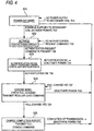
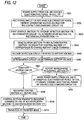
- Fig. 11 is a flowchart showing operation of the contactless charger 200 of the embodiment achieved in the charge stop mode.
- T5 is a cycle of load check timing
- T6 is a cycle of charge restart check timing (see Fig. 13 ).
- T5 is set to 0.1s (second)
- T6 is set to 100s.
- the timers start counting in accordance with a predetermined trigger signal from the control section 230, thereby starting counting T5 and T6 (step S102).
- step S104 When the T5 timer detects that T5 elapses 0.1s (YES; step S103), the contactless charger 200 ascertains presence/absence of load in accordance with foregoing procedures (step S104). When presence of load is checked (YES; step S105), the T5 timer resets a count of T5 by a predetermined trigger signal from the control section 230 and again starts counting (step S106). Processing then returns to step S103. In the meantime, when presence of load is not ascertained in step S105 (NO; step S105), the contactless charger 200 shifts to the standby mode in accordance with the foregoing procedures (step S107), and the charge stop mode ends.
- step S103 When the T5 timers does not detect, in step S103, that T5 has elapsed 0.1s (NO; step S103), a determination is made as to whether or not the count of T6 performed by the T6 timer has exceeded 100s (step S108).
- step S108 When the T6 timer does not detect that T6 has elapsed 100s (NO; step S108), processing again returns to step S103, and processing pertaining to procedures subsequent to the step is performed.
- the contactless charger 200 transmits the charge restart check command to the mobile phone 100 and awaits an answer from the mobile phone 100 (step S109).
- step S110 When a recharge command is present in the answer from the mobile phone 100 (YES; step S110), the contactless charger 200 shifts to the transmission mode in accordance with the foregoing procedures (step S111), and the charge stop mode ends.
- step S110 when the recharge command is not present in the answer from the mobile phone 100 (NO; step S110), the T6 timer resets a count of T6 in accordance with a predetermined trigger signal from the control section 230 and again starts counting operation (step S112), and processing returns to step S103.
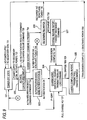
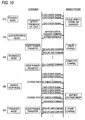
- Fig. 12 is a flowchart showing operation performed when restart of charge of the mobile phone 100 of the present embodiment is checked.
- a recharge start voltage that is detected by the voltage detection circuit 178 and that corresponds to a limit voltage at which recharge of the battery cell 160 is required is set to 3.9V.
- electromotive force arises in the coil 177 as a result of supply of electric power from the coil 280 of the contactless charger 200 (step S201).
- the rectifying circuit 176 rectifies the electromotive force, thereby generating a source voltage for the contactless charging circuit 170 (step S202).
- the control section 171, the voltage detection circuit 178, the determination circuit 179, the authentication section 173, and the demodulation section 174 are activated (step S203).
- the control section 171 Ascertains that a charge restart check command is included in an AC waveform of received AC power (step S204), and the voltage detection circuit 178 detects the voltage of the battery cell 160 (step S205). Further, the determination circuit 179 determines a detected battery voltage (step S206).
- the determination circuit 179 sends a report indicating recharge to the control section 171 (step S208).
- the control section 171 received the report sends a recharge command by way of the authentication section 172 and the modulation section 173 (step S209).
- the contactless charger 200 shifts to a transfer mode (step S210).
- step S207 when the result of determination rendered by the determination circuit 179 in step S207 is greater than 3.9V (NO; step S207), the determination circuit 179 sends a report indicating nonperformance of recharge to the control section 171 (step S211). Since the power supply from the coil 280 of the contactless charger 200 is interrupted, a decrease arises in electromotive force of the coil 177, and the power of the contactless charging circuit 170 is turned off (step S212).
- Fig. 13 is a view showing that operation timing of the contactless charger 200 is conceptually denoted as H or L.
- An H period shows that the charger 200 is in the course of operation (any of operation for transferring a load check signal and checking load, authentication operation, power transfer operation, and charge restart check operation), and an L period represents stoppage of signal transfer operation and power transfer operation.
- a standby mode (a), an authentication mode (b), a transfer mode (c), and an error mode (e) are common to Fig. 6 .
- a charge stop mode (d) is provided in lieu of the charge completion mode shown in Fig. 6 .
- a duration Te of the operation time of the load check signal is set so as to become equal to other operation times Ta, Tc, and Td.
- the present mode requires performance of a determination as to whether or not a recharge command is acquired from the mobile phone 100 after the contactless charger 200 has issued the charge restart check command. The operating state is continually held until the determination is completed, and hence the duration Tf of the operation time is comparatively large. In the present embodiment, the duration is set to a relationship of Ta ⁇ Tb ⁇ Tf.
- power consumption achieved at the time of operation of the contactless charger 200 is 1W and when power consumption achieved when operation of the charger is stopped is 0.01W, power consumption achieved in a standby mode is found to be 0.1090W, and power consumption achieved in a charge stop mode is found to be 0.1094W in terms of an average per hour. Even when the charge stop mode is adopted, power consumption can be understood to be reduced to a level essential equal to that achieved merely in the standby mode.
- the load check signal and the restart check command are intermittently generated and transmitted in a charge stop mode that is a charge stop state. Accordingly, there are provided a contactless charging system that enables automatic recharge and provides much enhanced usability in addition to yielding the advantage of the first embodiment and a contactless charger and an electronic device which are applied to the system.
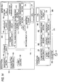
- Fig. 14 is a block diagram for describing the overview of a contactless charging system of a third embodiment of the present invention.
- the mobile phone 100 in the contactless charging system of the second embodiment is independently provided with a battery pack 400 including the coil 177, the protective circuit 150, and the battery cell 160.
- the battery pack 400 is configured so as to be removable from a main unit that is the other portion of the mobile phone 100 and independently tradable.
- Fig. 15 is a modification of the contactless charging system shown in Fig. 14 .
- the mobile phone 100 of the contactless charging system of the second embodiment is independently provided with the battery pack 400 that includes the overall contactless charging circuit 170, the protective circuit 150, and the battery cell 160.
- the battery pack 400 of the present embodiment includes the principal feature of the present invention and is configured so as to be removable from the main body that is the other part of the mobile phone 100 and independently tradable.
- the battery pack, the electronic device, the contactless charger, and the contactless charging system of the present invention provide superior usability; allow for a reduction in power consumption and a safety measure; and are useful for recharging various electronic devices, such as mobile phones.
Priority Applications (1)
| Application Number | Priority Date | Filing Date | Title |
|---|---|---|---|
| EP15152121.8A EP2882070B1 (en) | 2006-11-08 | 2006-11-08 | Non-contact charger and non-contact charge system |
Applications Claiming Priority (3)
| Application Number | Priority Date | Filing Date | Title |
|---|---|---|---|
| EP06823211.5A EP2086085B1 (en) | 2006-11-08 | 2006-11-08 | Non-contact charger and non-contact charge system |
| EP15152121.8A EP2882070B1 (en) | 2006-11-08 | 2006-11-08 | Non-contact charger and non-contact charge system |
| PCT/JP2006/322307 WO2008056415A1 (en) | 2006-11-08 | 2006-11-08 | Non-contact charger, electronic device, battery pack, and non-contact charge system |
Related Parent Applications (2)
| Application Number | Title | Priority Date | Filing Date |
|---|---|---|---|
| EP06823211.5A Division EP2086085B1 (en) | 2006-11-08 | 2006-11-08 | Non-contact charger and non-contact charge system |
| EP06823211.5A Division-Into EP2086085B1 (en) | 2006-11-08 | 2006-11-08 | Non-contact charger and non-contact charge system |
Publications (2)
| Publication Number | Publication Date |
|---|---|
| EP2882070A1 EP2882070A1 (en) | 2015-06-10 |
| EP2882070B1 true EP2882070B1 (en) | 2016-08-31 |
Family
ID=39364244
Family Applications (2)
| Application Number | Title | Priority Date | Filing Date |
|---|---|---|---|
| EP06823211.5A Active EP2086085B1 (en) | 2006-11-08 | 2006-11-08 | Non-contact charger and non-contact charge system |
| EP15152121.8A Active EP2882070B1 (en) | 2006-11-08 | 2006-11-08 | Non-contact charger and non-contact charge system |
Family Applications Before (1)
| Application Number | Title | Priority Date | Filing Date |
|---|---|---|---|
| EP06823211.5A Active EP2086085B1 (en) | 2006-11-08 | 2006-11-08 | Non-contact charger and non-contact charge system |
Country Status (4)
| Country | Link |
|---|---|
| US (3) | US8330414B2 (ja) |
| EP (2) | EP2086085B1 (ja) |
| JP (7) | JP4480048B2 (ja) |
| WO (1) | WO2008056415A1 (ja) |
Families Citing this family (116)
| Publication number | Priority date | Publication date | Assignee | Title |
|---|---|---|---|---|
| JP4480048B2 (ja) * | 2006-11-08 | 2010-06-16 | パナソニック株式会社 | 非接触充電器及び非接触充電システム |
| JP4494426B2 (ja) * | 2007-02-16 | 2010-06-30 | セイコーエプソン株式会社 | 送電制御装置、受電制御装置、無接点電力伝送システム、送電装置、受電装置および電子機器 |
| KR101061646B1 (ko) * | 2007-02-20 | 2011-09-01 | 세이코 엡슨 가부시키가이샤 | 송전 제어 장치, 송전 장치, 전자 기기 및 무접점 전력전송 시스템 |
| JP5121307B2 (ja) * | 2007-05-28 | 2013-01-16 | ソニーモバイルコミュニケーションズ株式会社 | 無接点電力伝送コイルユニット、携帯端末、送電装置、及び、無接点電力伝送システム |
| JP4743173B2 (ja) | 2007-06-29 | 2011-08-10 | セイコーエプソン株式会社 | 送電制御装置、送電装置、無接点電力伝送システムおよび電子機器 |
| WO2009069844A1 (en) * | 2007-11-30 | 2009-06-04 | Chun-Kil Jung | Multiple non-contact charging system of wireless power transmision and control method thereof |
| JP5398160B2 (ja) * | 2008-03-31 | 2014-01-29 | パナソニック株式会社 | 電子機器、充電器、及び電子機器充電システム |
| JP5159396B2 (ja) * | 2008-04-03 | 2013-03-06 | キヤノン株式会社 | 通信装置、その制御方法及びプログラム |
| JP2010016985A (ja) * | 2008-07-03 | 2010-01-21 | Sanyo Electric Co Ltd | 電力搬送における情報伝送方法とこの情報伝送方法を使用する充電台と電池内蔵機器 |
| JP5470764B2 (ja) * | 2008-07-16 | 2014-04-16 | セイコーエプソン株式会社 | 受電制御装置、受電装置、及び電子機器 |
| JP2010045960A (ja) * | 2008-07-16 | 2010-02-25 | Seiko Epson Corp | 送電制御装置、送電装置、受電制御装置、受電装置、電子機器、及び無接点電力伝送方法 |
| JP5432283B2 (ja) | 2008-12-12 | 2014-03-05 | ハンリム ポステック カンパニー リミテッド | 無接点電力受信装置及び受信装置用コアを製作するためのジグ |
| KR101083630B1 (ko) * | 2009-05-22 | 2011-11-17 | 정춘길 | 무접점 방식의 배터리 충전을 위한 제어모듈 배치 구조 |
| JP6235646B2 (ja) * | 2009-06-22 | 2017-11-22 | フェリカネットワークス株式会社 | 充電装置、制御方法、およびプログラム |
| JP5434330B2 (ja) * | 2009-07-22 | 2014-03-05 | ソニー株式会社 | 電力受信装置、電力伝送システム、充電装置および電力伝送方法 |
| CN102971934B (zh) * | 2009-08-19 | 2015-11-25 | 鲍尔马特技术有限公司 | 可感应充电的电源组 |
| US9312728B2 (en) * | 2009-08-24 | 2016-04-12 | Access Business Group International Llc | Physical and virtual identification in a wireless power network |
| FI20095973A0 (fi) | 2009-09-22 | 2009-09-22 | Powerkiss Oy | Induktiivinen tehonsyöttö |
| US9094054B2 (en) * | 2009-11-30 | 2015-07-28 | Broadcom Corporation | IC controlled wireless power operation and applications thereof including control channel communication configuration |
| JP5478298B2 (ja) * | 2010-02-25 | 2014-04-23 | オリンパス株式会社 | 携帯無線端末、無線端末装置および無線通信システム |
| US20110302078A1 (en) | 2010-06-02 | 2011-12-08 | Bryan Marc Failing | Managing an energy transfer between a vehicle and an energy transfer system |
| JP2012055086A (ja) * | 2010-09-01 | 2012-03-15 | Hitachi Maxell Energy Ltd | 充電ユニット及びそれを備えた電気機器 |
| KR101213086B1 (ko) * | 2010-11-04 | 2012-12-18 | 유한회사 한림포스텍 | 무선 전력 전송 장치에서의 무선 전력 신호 제어 방법 및 이를 이용하는 무선 전력 전송 장치 |
| DE102010054470A1 (de) * | 2010-12-14 | 2012-06-14 | Conductix-Wampfler Ag | Vorrichtung zur induktiven Übertragung elektrischer Energie |
| US9819209B2 (en) * | 2011-01-18 | 2017-11-14 | Texas Instrument Incorporated | Contactless charging of BLUETOOTH other wireless headsets |
| BR112013024390A2 (pt) * | 2011-03-31 | 2016-12-13 | Sony Corp | detector, transmissor e receptor de potência, sistema de alimentação de potência, e, método de detecção |
| KR20120135873A (ko) * | 2011-06-07 | 2012-12-17 | 삼성전자주식회사 | 무선 전력 전송 장치 및 시스템 |
| WO2013031054A1 (ja) * | 2011-08-31 | 2013-03-07 | Necカシオモバイルコミュニケーションズ株式会社 | 充電システム、電子機器、充電制御方法及びプログラム |
| JP5794056B2 (ja) * | 2011-09-12 | 2015-10-14 | ソニー株式会社 | 給電装置および給電システム |
| EP2765434B1 (en) | 2011-10-07 | 2020-04-08 | Hitachi Automotive Systems, Ltd. | Battery monitoring device and battery monitoring system |
| US9225185B2 (en) | 2011-10-21 | 2015-12-29 | Samsung Electronics Co., Ltd. | Method and apparatus for controlling charging in electronic device |
| EP2792046B1 (en) | 2011-12-14 | 2020-09-30 | Provenance Asset Group LLC | Method and apparatus for optimizing standby power consumption and providing user indications in wpc based wireless charging system |
| WO2013087970A1 (en) | 2011-12-14 | 2013-06-20 | Nokia Corporation | Method and apparatus for improving electronic devices wireless charging using inertial sensors |
| US9093857B2 (en) | 2011-12-20 | 2015-07-28 | Sony Corporation | Mobile device and charging apparatus |
| JP5849842B2 (ja) * | 2011-12-21 | 2016-02-03 | ソニー株式会社 | 給電装置、給電システムおよび電子機器 |
| JP5857861B2 (ja) * | 2011-12-21 | 2016-02-10 | ソニー株式会社 | 給電装置、給電システムおよび電子機器 |
| WO2013094126A1 (ja) * | 2011-12-22 | 2013-06-27 | パナソニック株式会社 | 電子機器及び電子機器充電システム |
| US9160180B2 (en) | 2011-12-29 | 2015-10-13 | Sony Corporation | Charging apparatus for charging a secondary battery with a wireless feeding method |
| WO2013102908A1 (en) * | 2012-01-08 | 2013-07-11 | Powermat Technologies Ltd | System and method for providing and controlling inductive power charging |
| JP2013212004A (ja) * | 2012-03-30 | 2013-10-10 | Tokai Rika Co Ltd | 充電器 |
| US9407106B2 (en) | 2012-04-03 | 2016-08-02 | Qualcomm Incorporated | System and method for wireless power control communication using bluetooth low energy |
| FR2989529B1 (fr) | 2012-04-12 | 2016-04-15 | Continental Automotive France | Procede et banc de charge par couplage magnetique |
| US9490649B2 (en) * | 2012-06-13 | 2016-11-08 | Toyota Motor Engineering & Manufacturing North America, Inc. | System and method for wireless charging |
| WO2014018971A1 (en) | 2012-07-27 | 2014-01-30 | Thoratec Corporation | Resonant power transfer systems with protective algorithm |
| WO2014018969A2 (en) | 2012-07-27 | 2014-01-30 | Thoratec Corporation | Resonant power transfer system and method of estimating system state |
| EP2878061B1 (en) | 2012-07-27 | 2023-10-25 | Tc1 Llc | Thermal management for implantable wireless power transfer systems |
| WO2014018973A1 (en) | 2012-07-27 | 2014-01-30 | Thoratec Corporation | Resonant power transmission coils and systems |
| WO2014018972A1 (en) | 2012-07-27 | 2014-01-30 | Thoratec Corporation | Computer modeling for resonant power transfer systems |
| EP2878060A4 (en) * | 2012-07-27 | 2016-04-06 | Thoratec Corp | WIRELESS BATTERY CHARGING |
| US9805863B2 (en) | 2012-07-27 | 2017-10-31 | Thoratec Corporation | Magnetic power transmission utilizing phased transmitter coil arrays and phased receiver coil arrays |
| US10383990B2 (en) | 2012-07-27 | 2019-08-20 | Tc1 Llc | Variable capacitor for resonant power transfer systems |
| WO2014018967A1 (en) | 2012-07-27 | 2014-01-30 | Thoratec Corporation | Self-tuning resonant power transfer systems |
| JP6116832B2 (ja) | 2012-09-03 | 2017-04-19 | 日立マクセル株式会社 | 非接触充電システム |
| JP6104539B2 (ja) * | 2012-09-06 | 2017-03-29 | 日立マクセル株式会社 | 非接触充電システム |
| KR101807335B1 (ko) * | 2012-10-19 | 2018-01-10 | 삼성전자주식회사 | 무선 전력 수신기 및 무선 전력 수신기의 슬립 모드 설정 방법 |
| DE102012021638A1 (de) * | 2012-11-02 | 2014-05-08 | Audi Ag | Verfahren zum Betreiben eines elektronischen Geräts, Ladevorrichtung zum Aufladen einer Batterie eines elektronischen Geräts sowie Kraftwagen |
| GB2508157A (en) * | 2012-11-21 | 2014-05-28 | Knightsbridge Portable Comm Sp | Induction charging with secure wireless communication |
| KR102039375B1 (ko) * | 2013-03-08 | 2019-11-04 | 삼성전자주식회사 | 무선 전력 송신기 및 그 제어 방법 |
| WO2014145895A1 (en) | 2013-03-15 | 2014-09-18 | Thoratec Corporation | Malleable tets coil with improved anatomical fit |
| US9680310B2 (en) | 2013-03-15 | 2017-06-13 | Thoratec Corporation | Integrated implantable TETS housing including fins and coil loops |
| TWI538344B (zh) * | 2013-04-12 | 2016-06-11 | 亞旭電腦股份有限公司 | 可無線充電的電子裝置 |
| TWI564701B (zh) * | 2013-04-23 | 2017-01-01 | 緯創資通股份有限公司 | 電子裝置以及充電方法 |
| EP2814133A1 (en) * | 2013-06-14 | 2014-12-17 | Knightsbridge Portable Communications SP | Restricted rechargeable mobile device |
| GB2518128B (en) * | 2013-06-20 | 2021-02-10 | Nokia Technologies Oy | Charging rechargeable apparatus |
| US20150006395A1 (en) * | 2013-07-01 | 2015-01-01 | Htc Corporation | Method for Wireless Charging Authentication and Related Wireless Charging System |
| JP6300465B2 (ja) * | 2013-08-09 | 2018-03-28 | キヤノン株式会社 | 受電装置、受電装置の制御方法、及びプログラム |
| JP6284315B2 (ja) | 2013-08-13 | 2018-02-28 | ローム株式会社 | 非接触給電システム、受信機器、およびアナログ回路 |
| JP6249673B2 (ja) | 2013-08-13 | 2017-12-20 | ローム株式会社 | 非接触給電システムおよび受信機器 |
| US9847666B2 (en) | 2013-09-03 | 2017-12-19 | Apple Inc. | Power management for inductive charging systems |
| JP2015053754A (ja) * | 2013-09-05 | 2015-03-19 | 日立マクセル株式会社 | 非接触充電システム及び二次電池パック |
| JP2015053794A (ja) | 2013-09-06 | 2015-03-19 | ローム株式会社 | 位置ずれ検出装置および電子機器 |
| US9837866B2 (en) | 2013-10-09 | 2017-12-05 | Apple Inc. | Reducing power dissipation in inductive energy transfer systems |
| US20190089183A9 (en) * | 2013-10-23 | 2019-03-21 | Apple Inc. | Transmitter and receiver communication for inductive power transfer systems |
| US10695476B2 (en) | 2013-11-11 | 2020-06-30 | Tc1 Llc | Resonant power transfer systems with communications |
| EP3069358B1 (en) | 2013-11-11 | 2019-06-12 | Tc1 Llc | Hinged resonant power transfer coil |
| WO2015070205A1 (en) | 2013-11-11 | 2015-05-14 | Thoratec Corporation | Resonant power transfer systems with communications |
| US9673784B2 (en) | 2013-11-21 | 2017-06-06 | Apple Inc. | Using pulsed biases to represent DC bias for charging |
| KR101788603B1 (ko) * | 2013-12-01 | 2017-10-20 | 엘지전자 주식회사 | 무선 전력 전송방법, 무선 전력 전송장치 및 무선 충전 시스템 |
| US20150229135A1 (en) * | 2014-02-10 | 2015-08-13 | Shahar Porat | Wireless load modulation |
| DE102014117488A1 (de) * | 2014-02-11 | 2015-08-13 | Peiker Acustic Gmbh & Co. Kg | Mobiltelefonhalteeinrichtung |
| US9847667B2 (en) * | 2014-02-26 | 2017-12-19 | Htc Corporation | Method of handling wireless charging authentication |
| US10610692B2 (en) | 2014-03-06 | 2020-04-07 | Tc1 Llc | Electrical connectors for implantable devices |
| JP6170853B2 (ja) * | 2014-03-11 | 2017-07-26 | オムロンオートモーティブエレクトロニクス株式会社 | 通信システム |
| US9973025B2 (en) * | 2014-04-29 | 2018-05-15 | Htc Corporation | Power providing equipment, mobile device, operating method of mobile device |
| US9685814B1 (en) * | 2014-06-13 | 2017-06-20 | Apple Inc. | Detection of coil coupling in an inductive charging system |
| CN107078518B (zh) | 2014-06-20 | 2020-02-28 | 苹果公司 | 用于检测异物的方法和无线电力发射器 |
| US10186760B2 (en) | 2014-09-22 | 2019-01-22 | Tc1 Llc | Antenna designs for communication between a wirelessly powered implant to an external device outside the body |
| US9583874B2 (en) | 2014-10-06 | 2017-02-28 | Thoratec Corporation | Multiaxial connector for implantable devices |
| JP6076315B2 (ja) | 2014-11-05 | 2017-02-08 | 本田技研工業株式会社 | 非接触充電システム |
| JP2016100922A (ja) | 2014-11-18 | 2016-05-30 | キヤノン株式会社 | 送電装置、送電装置の制御方法、プログラム |
| CN107408839B (zh) * | 2015-04-06 | 2020-08-28 | 松下知识产权经营株式会社 | 非接触供电装置及其控制装置 |
| US10148126B2 (en) | 2015-08-31 | 2018-12-04 | Tc1 Llc | Wireless energy transfer system and wearables |
| US10122217B2 (en) | 2015-09-28 | 2018-11-06 | Apple Inc. | In-band signaling within wireless power transfer systems |
| KR102408846B1 (ko) | 2015-10-07 | 2022-06-15 | 삼성전자주식회사 | 전자 장치, 충전 제어 방법 및 컴퓨터 판독가능 기록매체 |
| US10177604B2 (en) | 2015-10-07 | 2019-01-08 | Tc1 Llc | Resonant power transfer systems having efficiency optimization based on receiver impedance |
| US11689856B2 (en) | 2015-11-19 | 2023-06-27 | The Lovesac Company | Electronic furniture systems with integrated induction charger |
| CN105914905B (zh) * | 2016-04-25 | 2019-01-29 | 北京羽扇智信息科技有限公司 | 检测无线充电接收设备置于无线充电发射机的方法及装置 |
| JP6905313B2 (ja) * | 2016-05-16 | 2021-07-21 | キヤノン株式会社 | 給電装置、および、制御方法 |
| KR20180007117A (ko) | 2016-07-12 | 2018-01-22 | 삼성전자주식회사 | 무선 전력 송신기 및 무선 전력 수신기와 그 동작 방법 |
| DE102016217251A1 (de) * | 2016-09-09 | 2018-03-15 | Sauer Gmbh | Verfahren zum Bearbeiten eines Werkstücks aus Hartmetall für die Herstellung eines Werkzeuggrundkörpers an einer numerisch gesteuerten Werkzeugmaschine mit werkzeugtragender Arbeitsspindel |
| EP4084271A1 (en) | 2016-09-21 | 2022-11-02 | Tc1 Llc | Systems and methods for locating implanted wireless power transmission devices |
| US10601250B1 (en) | 2016-09-22 | 2020-03-24 | Apple Inc. | Asymmetric duty control of a half bridge power converter |
| WO2018136592A2 (en) | 2017-01-18 | 2018-07-26 | Tc1 Llc | Systems and methods for transcutaneous power transfer using microneedles |
| US10978899B2 (en) | 2017-02-02 | 2021-04-13 | Apple Inc. | Wireless charging system with duty cycle control |
| US10770921B2 (en) * | 2017-02-10 | 2020-09-08 | Apple Inc. | Wireless charging system with start-up negotiation |
| IT201700050638A1 (it) * | 2017-05-10 | 2018-11-10 | St Microelectronics Srl | Procedimento di funzionamento di dispositivi alimentati a radiofrequenza, circuito e dispositivo corrispondenti |
| US10283952B2 (en) | 2017-06-22 | 2019-05-07 | Bretford Manufacturing, Inc. | Rapidly deployable floor power system |
| EP3735733B1 (en) | 2018-01-04 | 2024-01-17 | Tc1 Llc | Systems and methods for elastic wireless power transmission devices |
| DE102019124928A1 (de) | 2018-09-28 | 2020-04-02 | Taiwan Semiconductor Manufacturing Company, Ltd. | Integriertes schaltungsdesign unter verwendung von fuzzy-maschinenlernen |
| US11392748B2 (en) * | 2018-09-28 | 2022-07-19 | Taiwan Semiconductor Manufacturing Company, Ltd. | Integrated circuit design using fuzzy machine learning |
| JP7278855B2 (ja) * | 2019-04-24 | 2023-05-22 | キヤノン株式会社 | 送電装置、送電装置が実行する制御方法、及びプログラム |
| JP6614627B1 (ja) * | 2019-07-31 | 2019-12-04 | 株式会社ビレッジフィールズ | 情報収集システム、情報収集方法、充電装置、情報収集装置、情報処理装置およびその制御プログラム |
| US10984164B1 (en) * | 2019-10-23 | 2021-04-20 | Cadence Design Systems, Inc. | Method, system, and product for generating and maintaining a physical design for an electronic circuit having sync group constraints for design rule checking |
| JP7425590B2 (ja) * | 2019-12-12 | 2024-01-31 | キヤノン株式会社 | 受電装置およびその制御方法、プログラム |
| JP6865879B1 (ja) * | 2020-09-07 | 2021-04-28 | 日本たばこ産業株式会社 | エアロゾル発生システム、吸引器用コントローラ、および電源装置 |
| WO2023248733A1 (ja) * | 2022-06-20 | 2023-12-28 | パナソニックIpマネジメント株式会社 | 充電装置 |
Family Cites Families (23)
| Publication number | Priority date | Publication date | Assignee | Title |
|---|---|---|---|---|
| US5115182A (en) * | 1990-04-23 | 1992-05-19 | Motorola, Inc. | Battery charging controller for a battery powered device and method for using the same |
| DE69832713T2 (de) * | 1997-02-26 | 2006-07-27 | Alfred E. Mann Foundation For Scientific Research, Santa Clarita | Batterie-betriebsgerät zur implantation in einem patienten |
| US6163131A (en) * | 1998-04-02 | 2000-12-19 | The Procter & Gamble Company | Battery having a built-in controller |
| JP2000037046A (ja) | 1998-07-15 | 2000-02-02 | Nippon Telegr & Teleph Corp <Ntt> | 非接触給電に用いる電力供給装置および負荷装置ならびに負荷装置検出方法 |
| JP2000060010A (ja) | 1998-08-05 | 2000-02-25 | Seiko Instruments Inc | 電子時計および電子時計用充電装置 |
| DE19837675A1 (de) * | 1998-08-19 | 2000-02-24 | Nokia Technology Gmbh | Ladevorrichtung für Akkumulatoren in einem mobilen elektrischen Gerät mit induktiver Energieübertragung |
| JP2000090220A (ja) | 1998-09-09 | 2000-03-31 | Hitachi Maxell Ltd | 非接触型icカードおよび非接触型icカードシステム |
| KR20020057469A (ko) | 2001-01-05 | 2002-07-11 | 윤종용 | 코어 없는 초박형 프린트회로기판 변압기 및 그프린트회로기판 변압기를 이용한 무접점 배터리 충전기 |
| US7233137B2 (en) | 2003-09-30 | 2007-06-19 | Sharp Kabushiki Kaisha | Power supply system |
| JP2005110412A (ja) | 2003-09-30 | 2005-04-21 | Sharp Corp | 電力供給システム |
| US6931332B2 (en) * | 2003-10-01 | 2005-08-16 | General Electric Company | Method and system for testing battery connectivity |
| JP2005143181A (ja) | 2003-11-05 | 2005-06-02 | Seiko Epson Corp | 非接触電力伝送装置 |
| JP4148183B2 (ja) * | 2004-05-18 | 2008-09-10 | 日立工機株式会社 | 充電装置 |
| JP2006060909A (ja) | 2004-08-19 | 2006-03-02 | Seiko Epson Corp | 非接触電力伝送装置 |
| JP2006115562A (ja) | 2004-10-12 | 2006-04-27 | Matsushita Electric Ind Co Ltd | 非接触充電型電池システム、充電装置および電池パック |
| JP2006141170A (ja) * | 2004-11-15 | 2006-06-01 | Sharp Corp | 電力供給システム及びこれに用いられる送電装置並びに受電装置 |
| JP4774217B2 (ja) | 2005-02-15 | 2011-09-14 | 高石 好 | 電力伝送装置、電力伝送方法 |
| JP2006230129A (ja) | 2005-02-18 | 2006-08-31 | Nanao Corp | 非接触電力供給装置 |
| KR100554889B1 (ko) * | 2005-03-21 | 2006-03-03 | 주식회사 한림포스텍 | 무접점 충전 시스템 |
| JP2006353042A (ja) * | 2005-06-17 | 2006-12-28 | Ntt Docomo Inc | 送電装置、受電装置、認証課金代行装置、充電システム、送電方法、受電方法、充電方法 |
| JP4155408B2 (ja) * | 2005-09-29 | 2008-09-24 | ソニー・エリクソン・モバイルコミュニケーションズ株式会社 | 充電装置および充電システム |
| JP4707626B2 (ja) | 2006-08-11 | 2011-06-22 | 三洋電機株式会社 | 無接点の充電器とこの充電器と携帯電子機器の組み合わせ |
| JP4480048B2 (ja) * | 2006-11-08 | 2010-06-16 | パナソニック株式会社 | 非接触充電器及び非接触充電システム |
-
2006
- 2006-11-08 JP JP2008542969A patent/JP4480048B2/ja active Active
- 2006-11-08 EP EP06823211.5A patent/EP2086085B1/en active Active
- 2006-11-08 WO PCT/JP2006/322307 patent/WO2008056415A1/ja active Application Filing
- 2006-11-08 US US12/513,145 patent/US8330414B2/en active Active
- 2006-11-08 EP EP15152121.8A patent/EP2882070B1/en active Active
-
2009
- 2009-11-11 JP JP2009258045A patent/JP2010034080A/ja active Pending
- 2009-11-11 JP JP2009258044A patent/JP5042294B2/ja not_active Expired - Fee Related
-
2011
- 2011-12-26 JP JP2011284067A patent/JP5186590B2/ja active Active
-
2012
- 2012-11-02 US US13/667,839 patent/US9407109B2/en active Active
- 2012-11-26 JP JP2012257712A patent/JP5555302B2/ja active Active
-
2013
- 2013-12-09 JP JP2013254421A patent/JP5509385B2/ja active Active
-
2014
- 2014-03-27 JP JP2014066390A patent/JP5830707B2/ja active Active
- 2014-04-03 US US14/244,615 patent/US9362779B2/en active Active
Also Published As
| Publication number | Publication date |
|---|---|
| US8330414B2 (en) | 2012-12-11 |
| EP2882070A1 (en) | 2015-06-10 |
| JP2014068531A (ja) | 2014-04-17 |
| JP2014113058A (ja) | 2014-06-19 |
| JP2013070610A (ja) | 2013-04-18 |
| JP5509385B2 (ja) | 2014-06-04 |
| JP5042294B2 (ja) | 2012-10-03 |
| JP2010034080A (ja) | 2010-02-12 |
| JP2012080772A (ja) | 2012-04-19 |
| JP5830707B2 (ja) | 2015-12-09 |
| WO2008056415A1 (en) | 2008-05-15 |
| US9362779B2 (en) | 2016-06-07 |
| JP5186590B2 (ja) | 2013-04-17 |
| EP2086085A1 (en) | 2009-08-05 |
| JP2010035417A (ja) | 2010-02-12 |
| EP2086085A4 (en) | 2012-08-22 |
| US20100066305A1 (en) | 2010-03-18 |
| JP5555302B2 (ja) | 2014-07-23 |
| JPWO2008056415A1 (ja) | 2010-02-25 |
| US20130057206A1 (en) | 2013-03-07 |
| EP2086085B1 (en) | 2015-04-15 |
| US20140217968A1 (en) | 2014-08-07 |
| JP4480048B2 (ja) | 2010-06-16 |
| US9407109B2 (en) | 2016-08-02 |
Similar Documents
| Publication | Publication Date | Title |
|---|---|---|
| EP2882070B1 (en) | Non-contact charger and non-contact charge system | |
| US8188709B2 (en) | Power transmission control device, power transmitting device, non-contact power transmitting system, and electronic instrument | |
| US8629651B2 (en) | Portable wireless charging device | |
| US8054036B2 (en) | Power transmission control device, power reception control device, non-contact power transmission system, power transmission device, power reception device, and electronic instrument | |
| US9191075B2 (en) | Wireless power control method, system, and apparatus utilizing a wakeup signal to prevent standby power consumption | |
| US20090174264A1 (en) | Power transmission control device, power transmitting device, non-contact power transmission system, electronic instrument, and power transmission control method | |
| US20130026983A1 (en) | Battery pack | |
| JP2011229265A (ja) | 非接触電力伝送装置 | |
| KR101063156B1 (ko) | 무접점 충전제어장치 및 충전제어방법 | |
| JP5426149B2 (ja) | 非接触電力伝送装置 | |
| KR20120023750A (ko) | 전동 차량 | |
| US20160126747A1 (en) | Non-contact power transmission apparatus and power transmission device | |
| JP6116832B2 (ja) | 非接触充電システム | |
| JP6862924B2 (ja) | 制御装置、受電装置及び電子機器 | |
| JP2012227986A (ja) | 電池パック、電力システムおよび電動車両 | |
| JP2009213294A (ja) | 非接触充電器 | |
| JP2017038455A (ja) | 充電制御システム | |
| KR101026220B1 (ko) | 무접점겸용충전장치 및 그의 제어방법 | |
| KR20100112033A (ko) | 무접점 충전 정위치 표시방법 및 그 장치 | |
| JP2018121487A (ja) | 受電装置 |
Legal Events
| Date | Code | Title | Description |
|---|---|---|---|
| PUAI | Public reference made under article 153(3) epc to a published international application that has entered the european phase |
Free format text: ORIGINAL CODE: 0009012 |
|
| 17P | Request for examination filed |
Effective date: 20150122 |
|
| AC | Divisional application: reference to earlier application |
Ref document number: 2086085 Country of ref document: EP Kind code of ref document: P |
|
| AK | Designated contracting states |
Kind code of ref document: A1 Designated state(s): AT BE BG CH CY CZ DE DK EE ES FI FR GB GR HU IE IS IT LI LT LU LV MC NL PL PT RO SE SI SK TR |
|
| GRAP | Despatch of communication of intention to grant a patent |
Free format text: ORIGINAL CODE: EPIDOSNIGR1 |
|
| RIC1 | Information provided on ipc code assigned before grant |
Ipc: H02J 7/02 20060101AFI20160229BHEP Ipc: H01M 10/44 20060101ALI20160229BHEP |
|
| INTG | Intention to grant announced |
Effective date: 20160317 |
|
| GRAS | Grant fee paid |
Free format text: ORIGINAL CODE: EPIDOSNIGR3 |
|
| GRAA | (expected) grant |
Free format text: ORIGINAL CODE: 0009210 |
|
| AC | Divisional application: reference to earlier application |
Ref document number: 2086085 Country of ref document: EP Kind code of ref document: P |
|
| AK | Designated contracting states |
Kind code of ref document: B1 Designated state(s): AT BE BG CH CY CZ DE DK EE ES FI FR GB GR HU IE IS IT LI LT LU LV MC NL PL PT RO SE SI SK TR |
|
| REG | Reference to a national code |
Ref country code: CH Ref legal event code: EP Ref country code: GB Ref legal event code: FG4D |
|
| REG | Reference to a national code |
Ref country code: IE Ref legal event code: FG4D |
|
| REG | Reference to a national code |
Ref country code: DE Ref legal event code: R096 Ref document number: 602006050173 Country of ref document: DE |
|
| REG | Reference to a national code |
Ref country code: AT Ref legal event code: REF Ref document number: 825725 Country of ref document: AT Kind code of ref document: T Effective date: 20161015 |
|
| REG | Reference to a national code |
Ref country code: FR Ref legal event code: PLFP Year of fee payment: 11 |
|
| REG | Reference to a national code |
Ref country code: LT Ref legal event code: MG4D |
|
| REG | Reference to a national code |
Ref country code: NL Ref legal event code: MP Effective date: 20160831 |
|
| REG | Reference to a national code |
Ref country code: AT Ref legal event code: MK05 Ref document number: 825725 Country of ref document: AT Kind code of ref document: T Effective date: 20160831 |
|
| PG25 | Lapsed in a contracting state [announced via postgrant information from national office to epo] |
Ref country code: FI Free format text: LAPSE BECAUSE OF FAILURE TO SUBMIT A TRANSLATION OF THE DESCRIPTION OR TO PAY THE FEE WITHIN THE PRESCRIBED TIME-LIMIT Effective date: 20160831 Ref country code: LT Free format text: LAPSE BECAUSE OF FAILURE TO SUBMIT A TRANSLATION OF THE DESCRIPTION OR TO PAY THE FEE WITHIN THE PRESCRIBED TIME-LIMIT Effective date: 20160831 |
|
| PG25 | Lapsed in a contracting state [announced via postgrant information from national office to epo] |
Ref country code: LV Free format text: LAPSE BECAUSE OF FAILURE TO SUBMIT A TRANSLATION OF THE DESCRIPTION OR TO PAY THE FEE WITHIN THE PRESCRIBED TIME-LIMIT Effective date: 20160831 Ref country code: AT Free format text: LAPSE BECAUSE OF FAILURE TO SUBMIT A TRANSLATION OF THE DESCRIPTION OR TO PAY THE FEE WITHIN THE PRESCRIBED TIME-LIMIT Effective date: 20160831 Ref country code: NL Free format text: LAPSE BECAUSE OF FAILURE TO SUBMIT A TRANSLATION OF THE DESCRIPTION OR TO PAY THE FEE WITHIN THE PRESCRIBED TIME-LIMIT Effective date: 20160831 Ref country code: BE Free format text: LAPSE BECAUSE OF NON-PAYMENT OF DUE FEES Effective date: 20161130 Ref country code: GR Free format text: LAPSE BECAUSE OF FAILURE TO SUBMIT A TRANSLATION OF THE DESCRIPTION OR TO PAY THE FEE WITHIN THE PRESCRIBED TIME-LIMIT Effective date: 20161201 Ref country code: ES Free format text: LAPSE BECAUSE OF FAILURE TO SUBMIT A TRANSLATION OF THE DESCRIPTION OR TO PAY THE FEE WITHIN THE PRESCRIBED TIME-LIMIT Effective date: 20160831 Ref country code: SE Free format text: LAPSE BECAUSE OF FAILURE TO SUBMIT A TRANSLATION OF THE DESCRIPTION OR TO PAY THE FEE WITHIN THE PRESCRIBED TIME-LIMIT Effective date: 20160831 |
|
| PG25 | Lapsed in a contracting state [announced via postgrant information from national office to epo] |
Ref country code: RO Free format text: LAPSE BECAUSE OF FAILURE TO SUBMIT A TRANSLATION OF THE DESCRIPTION OR TO PAY THE FEE WITHIN THE PRESCRIBED TIME-LIMIT Effective date: 20160831 Ref country code: EE Free format text: LAPSE BECAUSE OF FAILURE TO SUBMIT A TRANSLATION OF THE DESCRIPTION OR TO PAY THE FEE WITHIN THE PRESCRIBED TIME-LIMIT Effective date: 20160831 |
|
| PG25 | Lapsed in a contracting state [announced via postgrant information from national office to epo] |
Ref country code: CZ Free format text: LAPSE BECAUSE OF FAILURE TO SUBMIT A TRANSLATION OF THE DESCRIPTION OR TO PAY THE FEE WITHIN THE PRESCRIBED TIME-LIMIT Effective date: 20160831 Ref country code: PT Free format text: LAPSE BECAUSE OF FAILURE TO SUBMIT A TRANSLATION OF THE DESCRIPTION OR TO PAY THE FEE WITHIN THE PRESCRIBED TIME-LIMIT Effective date: 20170102 Ref country code: SK Free format text: LAPSE BECAUSE OF FAILURE TO SUBMIT A TRANSLATION OF THE DESCRIPTION OR TO PAY THE FEE WITHIN THE PRESCRIBED TIME-LIMIT Effective date: 20160831 Ref country code: DK Free format text: LAPSE BECAUSE OF FAILURE TO SUBMIT A TRANSLATION OF THE DESCRIPTION OR TO PAY THE FEE WITHIN THE PRESCRIBED TIME-LIMIT Effective date: 20160831 Ref country code: BE Free format text: LAPSE BECAUSE OF FAILURE TO SUBMIT A TRANSLATION OF THE DESCRIPTION OR TO PAY THE FEE WITHIN THE PRESCRIBED TIME-LIMIT Effective date: 20160831 Ref country code: PL Free format text: LAPSE BECAUSE OF FAILURE TO SUBMIT A TRANSLATION OF THE DESCRIPTION OR TO PAY THE FEE WITHIN THE PRESCRIBED TIME-LIMIT Effective date: 20160831 Ref country code: BG Free format text: LAPSE BECAUSE OF FAILURE TO SUBMIT A TRANSLATION OF THE DESCRIPTION OR TO PAY THE FEE WITHIN THE PRESCRIBED TIME-LIMIT Effective date: 20161130 |
|
| REG | Reference to a national code |
Ref country code: DE Ref legal event code: R097 Ref document number: 602006050173 Country of ref document: DE |
|
| PG25 | Lapsed in a contracting state [announced via postgrant information from national office to epo] |
Ref country code: IT Free format text: LAPSE BECAUSE OF FAILURE TO SUBMIT A TRANSLATION OF THE DESCRIPTION OR TO PAY THE FEE WITHIN THE PRESCRIBED TIME-LIMIT Effective date: 20160831 |
|
| REG | Reference to a national code |
Ref country code: CH Ref legal event code: PL |
|
| PLBE | No opposition filed within time limit |
Free format text: ORIGINAL CODE: 0009261 |
|
| STAA | Information on the status of an ep patent application or granted ep patent |
Free format text: STATUS: NO OPPOSITION FILED WITHIN TIME LIMIT |
|
| PG25 | Lapsed in a contracting state [announced via postgrant information from national office to epo] |
Ref country code: CH Free format text: LAPSE BECAUSE OF NON-PAYMENT OF DUE FEES Effective date: 20161130 Ref country code: LI Free format text: LAPSE BECAUSE OF NON-PAYMENT OF DUE FEES Effective date: 20161130 |
|
| 26N | No opposition filed |
Effective date: 20170601 |
|
| REG | Reference to a national code |
Ref country code: IE Ref legal event code: MM4A |
|
| PG25 | Lapsed in a contracting state [announced via postgrant information from national office to epo] |
Ref country code: SI Free format text: LAPSE BECAUSE OF FAILURE TO SUBMIT A TRANSLATION OF THE DESCRIPTION OR TO PAY THE FEE WITHIN THE PRESCRIBED TIME-LIMIT Effective date: 20160831 |
|
| PG25 | Lapsed in a contracting state [announced via postgrant information from national office to epo] |
Ref country code: LU Free format text: LAPSE BECAUSE OF NON-PAYMENT OF DUE FEES Effective date: 20161130 |
|
| REG | Reference to a national code |
Ref country code: FR Ref legal event code: PLFP Year of fee payment: 12 |
|
| PG25 | Lapsed in a contracting state [announced via postgrant information from national office to epo] |
Ref country code: IE Free format text: LAPSE BECAUSE OF NON-PAYMENT OF DUE FEES Effective date: 20161108 |
|
| PG25 | Lapsed in a contracting state [announced via postgrant information from national office to epo] |
Ref country code: HU Free format text: LAPSE BECAUSE OF FAILURE TO SUBMIT A TRANSLATION OF THE DESCRIPTION OR TO PAY THE FEE WITHIN THE PRESCRIBED TIME-LIMIT; INVALID AB INITIO Effective date: 20061108 |
|
| PG25 | Lapsed in a contracting state [announced via postgrant information from national office to epo] |
Ref country code: IS Free format text: LAPSE BECAUSE OF FAILURE TO SUBMIT A TRANSLATION OF THE DESCRIPTION OR TO PAY THE FEE WITHIN THE PRESCRIBED TIME-LIMIT Effective date: 20160831 Ref country code: MC Free format text: LAPSE BECAUSE OF FAILURE TO SUBMIT A TRANSLATION OF THE DESCRIPTION OR TO PAY THE FEE WITHIN THE PRESCRIBED TIME-LIMIT Effective date: 20160831 Ref country code: CY Free format text: LAPSE BECAUSE OF FAILURE TO SUBMIT A TRANSLATION OF THE DESCRIPTION OR TO PAY THE FEE WITHIN THE PRESCRIBED TIME-LIMIT Effective date: 20160831 |
|
| PG25 | Lapsed in a contracting state [announced via postgrant information from national office to epo] |
Ref country code: TR Free format text: LAPSE BECAUSE OF FAILURE TO SUBMIT A TRANSLATION OF THE DESCRIPTION OR TO PAY THE FEE WITHIN THE PRESCRIBED TIME-LIMIT Effective date: 20160831 |
|
| REG | Reference to a national code |
Ref country code: DE Ref legal event code: R084 Ref document number: 602006050173 Country of ref document: DE |
|
| PGFP | Annual fee paid to national office [announced via postgrant information from national office to epo] |
Ref country code: GB Payment date: 20231123 Year of fee payment: 18 |
|
| PGFP | Annual fee paid to national office [announced via postgrant information from national office to epo] |
Ref country code: FR Payment date: 20231120 Year of fee payment: 18 Ref country code: DE Payment date: 20231121 Year of fee payment: 18 |
|
| REG | Reference to a national code |
Ref country code: DE Ref legal event code: R081 Ref document number: 602006050173 Country of ref document: DE Owner name: PANASONIC AUTOMOTIVE SYSTEMS CO., LTD., YOKOHA, JP Free format text: FORMER OWNER: PANASONIC CORPORATION, KADOMA-SHI, OSAKA, JP |