EP2878554B1 - Bande de transport télescopique - Google Patents
Bande de transport télescopique Download PDFInfo
- Publication number
- EP2878554B1 EP2878554B1 EP14003806.8A EP14003806A EP2878554B1 EP 2878554 B1 EP2878554 B1 EP 2878554B1 EP 14003806 A EP14003806 A EP 14003806A EP 2878554 B1 EP2878554 B1 EP 2878554B1
- Authority
- EP
- European Patent Office
- Prior art keywords
- telescopic
- conveyor section
- base
- guide trough
- guide
- Prior art date
- Legal status (The legal status is an assumption and is not a legal conclusion. Google has not performed a legal analysis and makes no representation as to the accuracy of the status listed.)
- Active
Links
- 238000009434 installation Methods 0.000 claims 1
- 230000008878 coupling Effects 0.000 description 4
- 238000010168 coupling process Methods 0.000 description 4
- 238000005859 coupling reaction Methods 0.000 description 4
- 239000000463 material Substances 0.000 description 3
- 238000006073 displacement reaction Methods 0.000 description 2
- 238000000926 separation method Methods 0.000 description 2
- 239000002131 composite material Substances 0.000 description 1
- 239000002184 metal Substances 0.000 description 1
- 230000000284 resting effect Effects 0.000 description 1
Images


Classifications
-
- B—PERFORMING OPERATIONS; TRANSPORTING
- B65—CONVEYING; PACKING; STORING; HANDLING THIN OR FILAMENTARY MATERIAL
- B65G—TRANSPORT OR STORAGE DEVICES, e.g. CONVEYORS FOR LOADING OR TIPPING, SHOP CONVEYOR SYSTEMS OR PNEUMATIC TUBE CONVEYORS
- B65G15/00—Conveyors having endless load-conveying surfaces, i.e. belts and like continuous members, to which tractive effort is transmitted by means other than endless driving elements of similar configuration
- B65G15/22—Conveyors having endless load-conveying surfaces, i.e. belts and like continuous members, to which tractive effort is transmitted by means other than endless driving elements of similar configuration comprising a series of co-operating units
- B65G15/26—Conveyors having endless load-conveying surfaces, i.e. belts and like continuous members, to which tractive effort is transmitted by means other than endless driving elements of similar configuration comprising a series of co-operating units extensible, e.g. telescopic
-
- B—PERFORMING OPERATIONS; TRANSPORTING
- B65—CONVEYING; PACKING; STORING; HANDLING THIN OR FILAMENTARY MATERIAL
- B65G—TRANSPORT OR STORAGE DEVICES, e.g. CONVEYORS FOR LOADING OR TIPPING, SHOP CONVEYOR SYSTEMS OR PNEUMATIC TUBE CONVEYORS
- B65G21/00—Supporting or protective framework or housings for endless load-carriers or traction elements of belt or chain conveyors
- B65G21/10—Supporting or protective framework or housings for endless load-carriers or traction elements of belt or chain conveyors movable, or having interchangeable or relatively movable parts; Devices for moving framework or parts thereof
- B65G21/14—Supporting or protective framework or housings for endless load-carriers or traction elements of belt or chain conveyors movable, or having interchangeable or relatively movable parts; Devices for moving framework or parts thereof to allow adjustment of length or configuration of load-carrier or traction element
-
- B—PERFORMING OPERATIONS; TRANSPORTING
- B65—CONVEYING; PACKING; STORING; HANDLING THIN OR FILAMENTARY MATERIAL
- B65G—TRANSPORT OR STORAGE DEVICES, e.g. CONVEYORS FOR LOADING OR TIPPING, SHOP CONVEYOR SYSTEMS OR PNEUMATIC TUBE CONVEYORS
- B65G21/00—Supporting or protective framework or housings for endless load-carriers or traction elements of belt or chain conveyors
- B65G21/20—Means incorporated in, or attached to, framework or housings for guiding load-carriers, traction elements or loads supported on moving surfaces
- B65G21/2045—Mechanical means for guiding or retaining the load on the load-carrying surface
- B65G21/2063—Mechanical means for guiding or retaining the load on the load-carrying surface comprising elements not movable in the direction of load-transport
- B65G21/2072—Laterial guidance means
Definitions
- the invention relates to a telescopic conveyor belt according to the preamble of claim 1, as it is known from US 2,166,447 A is known.
- a similar telescopic conveyor is from the EP 1 559 668 B1 known and is used in particular for the loading and unloading of holds or containers. This is to prevent that general cargo such as packages or cartons can fall off the conveyor.
- For this purpose are from the US 3,127,978 F Guiding sections are known, which are mounted along the frame of the conveyor. However, it is disadvantageous that the guide sections did not extend along the individual telescoping conveyor sections.
- the object of the invention is to provide a telescopic conveyor belt with a lateral guide for transported objects, so that they can not fall laterally from the conveyor belt. In this case, a compact and in the retracted state of the telescopic conveyor space-saving design is sought. In addition, gaps, openings and cross-sectional tapers should be avoided, and it should be reliably prevented that smaller piece goods or parts thereof, such as belts, straps, buckles, etc., can get under the conveyor belt.
- the support region of the base guide trough directly adjoins the guide regions of the base guide trough or is connected to these in full length, so that a closed trough shape is formed. Furthermore, it can be provided that the support region of the telescopic guide trough directly adjoins the guide regions of the telescopic guide trough or is connected to these in full length, so that a closed trough shape is formed.
- a plurality of successive telescopic conveyor sections can be telescopically extendable and retractable in and against the extension direction, in particular held thereon.
- Each telescopic conveyor section may be associated with a telescopic guide trough, wherein an end remote from the base conveyor section of each telescopic guide trough may be coupled to an extension end of the respective telescopic conveyor section.
- each telescopic conveying section are assigned a plurality of telescopic guide tubes, each comprising an extractive guide trough and at least one follower trough coupled thereto, one end remote from the base conveyor section of each extension guide trough having an extension end of the respective telescoping conveyor section and an end of each extension guide trough facing the base conveyor section is coupled to a follower trough via an outflow limiting stop.
- each further follow-up sump is coupled to a follow-up sump adjoining in the direction of the extension guide sump via an outflow limiting stop.
- each individual guide trough whether telescopic guide trough, pull-out trough or follow-on trough, within the opposite direction to the extension, or in the direction As seen from the base conveyor section, the next leading trough, whether telescopic trough, pull-out trough or follow-on trough, is arranged, wherein the base trough adjacent trough is disposed within the base trough.
- Such an arrangement has the advantage that during operation of the telescopic conveyor belt in a preferred conveying direction, wherein the upper strand of the conveyor belt moves against the extension direction or in other words from an extension end of the telescopic conveyor in the direction of the base conveyor section, no obstruction or Verklemmrial between formed adjacent guide troughs can occur as the cross-sectional dimensions of each guide trough in the direction of the base guide trough and thus in the preferred direction of conveyance increase and not shrink, which would be the case with a reverse arrangement. All such telescopic, pull-out, follow-up or base guide troughs have the closed trough shape described above.
- a height difference between two adjacent guide troughs is not more than 2 times, 1.5 times or 1 times a material thickness of the support region of the overlying guide trough.
- Supporting areas of adjacent guide troughs can thus lie on one another directly or at a small distance. This results in a practically flat conveying surface, since the material thickness of the support areas in relation to their length is very small, for example 5 - 20mm at a length of up to 1 m, 2 m, 3 m or more.
- the support areas of adjacent guide troughs in the fully extended state are at the same height.
- This can be achieved by coupling an extension end of a telescoping conveying section with vertical clearance to an end of the or a telescopic guide trough or a pull-out guide trough facing the base conveyor section.
- a vertical slot can be arranged on the telescopic guide trough or on each pullout guide trough and on the extension end a fastening bolt passing through the slot, or vice versa.
- the telescopic guide trough is guided longitudinally displaceable by means of guide elements such as rollers or sliders on the base guide trough. Accordingly, the or each pullout guide trough can be guided by means of guide elements such as rollers or sliders on a follow-up trough coupled thereto so as to be longitudinally displaceable.
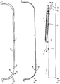
- a first embodiment of a telescopic conveyor is in Fig. 1 and 2 explained.
- the telescopic conveyor belt 2 has a base conveyor section 4, which may be formed, for example, by a machine frame, or the like, on support elements 6 such as feet, rollers, drive wheels. be on a ground or on it can be moved.
- a first telescopic conveyor section 8 is mounted in and out of retractable extension direction 7 and retractable, on which in turn a second telescopic conveyor section 10 is held extendable and retractable.
- On the base conveyor section 4 is a cross-sectionally substantially U-shaped, downwardly closed base guide trough 12 is held. Within and above the base guide trough 12, a first telescopic guide trough 14 is arranged, within which in turn a second telescopic guide trough 16 is arranged.
- each guide tray has a support region 20 which can be essentially planar and laterally directly, without clearance or longitudinal gap, elevated guide regions adjacent to the support region 22 has. All Leitwannen thus have over their full length a closed down trough shape, which reliably prevents falling out even small objects.
- An in Fig. 3 and 6 but not in Fig. 1 and 2 illustrated conveyor belt 26 is endlessly guided around the base conveyor section 4 and the telescopic conveyor sections 8, 10, as is well known in telescopic conveyors, with a disposed within the base conveyor section drive and a belt storage mechanism with which the change in length of the extended portions of Telescopic conveyor sections can be compensated.
- An upper run of the conveyor belt 26 extends on top of the base conveyor section 4 and the telescopic conveyor sections 8, 10, wherein the guide troughs 12, 14 and 16 between the conveyor belt 26 and the base conveyor section 4 and the first and second telescopic conveyor section 8, 10 are arranged.
- the top of the support portion 20 of the guide troughs 12, 14, 16 thus forms a bearing surface for a bottom or inside of the conveyor belt in the region of its upper run, while the guide portions 22 prevent slipping or falling individual pieces of goods from the conveyor belt.
- the telescopic conveyor 2 operates in a conveying direction 30, which is directed against the extension direction 7, wherein the upper run of the conveyor belt 26 moves in the conveying direction 30, so that, for example, a container located within range of the telescopic telescopic conveyor sections 8, 10th is, in the conveying direction 30 can be unloaded.
- the conveying direction is reversed, if necessary.
- the first telescopic guide trough 14 is coupled with its rear end 14a seen in the conveying direction 30 with the first telescopic conveyor section 8, in particular with its extension end 8a.
- the second telescopic guide trough 16 is coupled to the second telescoping conveyor section 10, and expediently with its extension end 10a.
- the length of the base guide trough 12 substantially corresponds to the length of the base conveyor section 4
- the length of the first telescopic guide trough 14 essentially corresponds to an extension path of the first telescopic conveyor section 8 and the length of the second telescope guide trough 16 substantially to one Extension path of the second telescopic conveyor section 10, it is ensured that in each extended position of the telescopic conveyor belt 2, the telescopic guide troughs 12, 14, 16 are at least partially overlapping each other and an uninterrupted support surface for the conveyor belt in the form of support portions 20 and a form gapless bottom and side guide for cargo in the form of the guide portions 22 and optionally the lateral edges of the support portions 20.
- Fig. 3 to 5 illustrate a first variant of the storage of the longitudinally displaceable guide vanes arranged one inside the other, wherein for the sake of simplicity, only the base guide trough 12 and the first telescopic guide trough 14 are shown.
- the in Fig. 3 to 7 can be basically any suitable and expedient form, for example, may be concave, and that the guide portions 22 may assume any suitable and expedient form, for example, vertically (in the vertical direction 32) may run, or be any angled or curved can.
- the guide troughs may be made of metal, plastic or a composite material.
- the under-and outside the first telescopic guide trough 14 arranged base guide trough 12 has a vertically upwardly freely ending guide region 22, on which a horizontal guide flange 22a is arranged.
- the upper and inside the base guide trough 12 arranged first telescopic guide trough 14, however, is provided at the upper end of its guide portion 22 with an inverted U-shaped guide profile 22b, which overlaps the guide portion 22 of the base guide trough 12 and arranged in pairs to the horizontal Rotary axes rotatable vertical guide rollers 34 and paired, rotatable about vertical axes of rotation horizontal guide rollers 36 are held.
- the horizontal guide rollers 36 run and prevent horizontal displacement of the two guide troughs 12, 14 relative to each other.
- Fig. 6 shows a variant of the leadership of the guide troughs by means of plastic rails 40 which are mounted on the underside of the first telescopic guide trough 14 and slide on the top or inside of the base guide trough 12.
- Fig. 7 shows plastic or other easily lubricious material existing guide troughs, which can be dispensed with separate guide elements such as rollers or plastic rails.
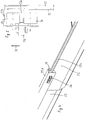
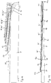
- FIG. 8 to 11 illustrate a second embodiment of a telescopic conveyor belt, wherein on the base conveyor section 4, an attachment 50 for increased assembly seen in the extension 7 rear end, or the telescopic conveyor sections 8, 10 facing away from the end 12 b of the base guide trough 12 is arranged so that the base guide trough 12 has a gradient opposite to the extension direction 7 or in the direction of the telescopic conveyor sections 8, 10.
- the attachment 50 serves, in particular, for the purpose of arranging the delivery end of the telescopic conveyor 2 formed by the front end 12b of the base guide trough 2 higher relative to the base conveyor section 4, so that a further conveyor can be placed underneath.
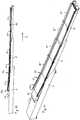
- Fig. 8 shows, in the retracted state, not only the base guide trough 12 but also the telescoped first and second telescopic guide troughs 14, 16, respectively a relative to the base conveyor section 4 and the extension direction 7 of the telescopic conveyor sections 8, 10 inclined position.
- each telescopic conveyor section 8, 10 is assigned not only a telescopic guide trough, but two guide troughs in the form of a coupled to the first telescopic conveyor section 8 first pullout guide trough 14 'and a with this coupled first follower guide trough 14 ", and in the form of a second pull-out guide trough 16 'coupled to the second telescopic conveyor section 10 and a second follower trough 16" coupled thereto.
- the follower trays 14 ", 16" are coupled to the pull-out guide troughs 14 ', 16' via a stop limiting stop.
- Each follow-up tray can be adjusted according to the extension ladder assigned to it Fig. 3 to 7 be stored.
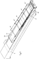
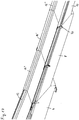
- FIGS. 12 and 13 show a third embodiment, which differs from the second embodiment 8 to 11 differs in that on each telescoping conveyor section 8, 10 not only an extract guide trough and coupled with this follower trough are present, but that each telescopic conveyor section three guide troughs are provided, namely on the first telescopic conveyor section 8 coupled thereto first pullout guide trough 14 ', a first follower trough 14 "coupled thereto and a further first follower trough 14"' coupled thereto, and on the second telescopic conveying section 10 a second pullout guide trough 16 'coupled thereto, one with this coupled second secondary side trough 16 "and in turn coupled to this another second secondary side trough 16"'. All follow-up trays are coupled with each other and with the respective pull-out guide trough via limiting stops, and they can be connected to the respective associated pull-out guide trough Fig. 3 to 7 be stored.
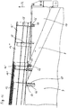
- FIGS. 14 and 15 show a fourth embodiment of a telescopic conveyor belt according to the invention, wherein in the region of the base conveyor section 4 additionally a wedge element 60 is provided.
- Fig. 14 shows the telescopic conveyor belt in the retracted position
- Fig. 15 shows the extended position.
- the wedge member 60 is between the base conveyor section 4 and with this coupled base guide trough 12 and connected to the first telescopic conveyor section 8.
- the wedge element 60 is thus displaced in the extension direction 7 relative to the base conveyor section 4 and the base guide trough 12 and passes, as Fig.
- first telescopic guide trough 14 shows, between the first telescopic guide trough 14 and the extended first telescopic conveyor section 8, so that the base guide trough 12 is raised relative to the base conveyor section 4.
- the telescopic conveyor belt according to the fourth embodiment in contrast to the second embodiment not only two, but three extendable telescopic conveyor sections, namely a first, relative to the base conveyor section 4 extendable and guided on this telescopic conveyor section 8, a second, relatively to the first telescopic conveyor section 8 extendable and guided on this telescopic conveyor section 10 and a third, relative to the second telescopic conveyor section 10 extendable and guided on this telescopic conveyor section 11.
- first telescopic Leit trough could be arranged, as in the first embodiment, are on it as in the second embodiment, a first pullout guide trough 14 'and coupled thereto first follower trough 14 "arranged, with a seen in the extension direction 7 front end of the first pullout guide trough 14' at an extension end 8a of the first Telescopic conveyor section 8 is held.
- a second extension guide trough 16 'and a second conveyor trough 16 "coupled thereto are arranged on the second telescopic conveyor section 10, wherein a front end seen in the extension direction 7 of the second pullout guide trough 16' with an extension end 10a of the second telescope
- a third separation guide trough 17 'and a third follower trough 17 "coupled thereto are arranged in a corresponding manner on the third part conveying section 11, a front end of the third separation guide trough 17' seen in the extension direction 7. is held on an extension end 11 a of the third telescopic conveying section 11.
- the wedge member 60 is thus after in the extended state Fig. 13 between the first telescopic conveyor section 8 and the first pull-out guide trough 14 'and the following guide trough 14 "and lifts them from the first telescopic conveyor section 8.
- the wedge element 60 has a sufficient length, so that it is in the extended state of the telescopic conveyor after Fig. 15 not only on the first telescopic conveyor section 8, but also partially on the base conveyor section 4, so that also the telescopic conveyor sections 8, 10 facing or viewed in the extension 7 front end 12a of the base guide trough 12 on the wedge element 60 is located and is lifted by this.
- the base guide trough can be fixedly attached to the base conveyor section 4, and the telescopic guide troughs 14, 16 can each be firmly connected to the telescopic conveyor sections 8, 10, since it is not necessarily to the height changes of the extension and retraction Telescopic guide tubes are coming. Nevertheless, it may be expedient if the first and second telescopic guide trough 14, 16 are mounted with vertical play on the telescopic conveyor sections 8, 10, so that seen in the extension direction 7 front ends of the telescopic guide troughs 14, 16, at the Ausfahrenden 8a, 10a are held, in the extended state ( Fig. 2 ) alslieiegen on the respective telescopic conveyor section.
- first telescopic guide trough 14 is located inside and on the base guide trough 12 and the second telescopic guide trough 16 is located inside and on the first telescopic guide trough 14, according to FIG Fig. 7 , or via guide elements according to Fig. 3 or Fig. 6 supported, which inevitably results in the extended state, a vertical distance between a telescopic conveyor section and a telescopic guide trough arranged above it, which is the greater, the more telescopic guide troughs are arranged one inside the other and the larger whose thickness dimensions are. Such a distance, however, is undesirable, but the guide troughs should rest on the telescopic conveyor sections.
- the telescopic guide troughs are held at their front end seen in the extension with vertical play on the telescopic conveyor sections, as in Fig. 16 is shown.
- a horizontal fastening bolt 64 is arranged, which engages in a vertically aligned slot 66 of a respective telescopic Leitwanne or pull-out guide trough 14 ', 16' and follower.
- front end of the extension guide troughs 14 ', 16' is on both sides of the respective telescopic conveyor section 8, 10 each mounted a mounting bracket 68 in which a slot 66 is introduced, so that a pivotable about a horizontal transverse axis and also height-adjustable coupling between a pull-out ladder and a telescoping conveyor section is made.
- the base guide trough 12 is supported with vertical play on the base conveyor section 4, which is also shown in FIG Fig. 16 is shown.
- the base guide trough 12 is raised or lowered relative to the base conveyor section 4, so that said vertical movement possibility is provided.
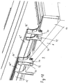
- first abstract limiting stops 70 which prevent an excessively broad excerpt of individual follow-up trays with respect to them leading extractive guide troughs.
- lateral guide elements 72 and support guide elements 74 with which individual follow-up trays are guided longitudinally displaceably on the telescopic conveyor section carrying them laterally and resting.
- Fig. 19 shows two lateral guide elements 72 and two support-guide elements 74 in cooperation with a second telescoping conveyor section 10 exemplified.
Landscapes
- Engineering & Computer Science (AREA)
- Mechanical Engineering (AREA)
- Structure Of Belt Conveyors (AREA)
- Attitude Control For Articles On Conveyors (AREA)
Claims (8)
- Bande transporteuse télescopique (2), comportant une section du transporteur de base (4), une section de transport télescopique (8), qui est tenue sur la section du transporteur de base (4) et qui peut se déployer et se rétracter de manière télescopique, dans le sens de l'extension (7) et aussi dans le sens contraire, ceci par rapport à la section du transporteur de base (4), une bande transporteuse (26) à circulation sans fin (26) qui constitue une surface de transport et qui, en cours de défilement, est menée le long d'une surface supérieure de la section du transporteur de base (4) et de la section de transport télescopique (8), une auge de guidage de base (12), qui est fermée sur le dessous, qui est placée entre la bande transporteuse (26) et la section du transporteur de base (4) et qui comporte une surface portante (20) servant à recevoir la bande transporteuse (26) et qui comprend également des éléments de guidage surélevés (22) qui suivent latéralement la surface portante (20), et une auge de guidage télescopique (14), qui est fermée sur le dessous, qui est placée entre la bande transporteuse (26) et la section du transporteur de base (4) et qui comporte une surface portante (20) servant à recevoir la bande transporteuse (26) et qui comprend également des éléments de guidage surélevés (22) qui suivent latéralement la surface portante (20), caractérisée en ce que l'auge de guidage de base (12) est raccordée à la section du transporteur de base (4) et l'auge de guidage télescopique (14) est raccordée à une extrémité d'extension (8a) de la section de transport télescopique (8), caractérisée en ce que l'auge de guidage télescopique (14) peut se déployer et s'escamoter de manière télescopique, par rapport à l'auge de guidage de base (12), et caractérisée en ce que la bande transporteuse télescopique (2) est ajustable entre une position emboîtée, dans laquelle la section de transport télescopique (8) est rétractée, ceci par rapport à la section du transporteur de base (4), et
caractérisée en ce que l'auge de guidage télescopique (14) est rétractée de manière télescopique, par rapport à l'auge de guidage de base (12), et une position déployée dans laquelle la section de transport télescopique (8) se déploie du moins en partie, ceci par rapport à l'auge de guidage de base (12),
caractérisée en ce qu'il est disposé, sur la section du transporteur de base (4), un couvercle (50) pour l'installation surélevée d'une extrémité (12b) de l'auge de guidage de base (12) tournée dans le sens contraire à celui de la section de transport télescopique (8), l'auge de guidage de base (12) étant disposée sur une pente dans le sens de la section de transport télescopique (8), et
en ce qu'un élément en forme de coin (60) est tenu sur la section du transporteur de base (4) de telle manière qu'il peut être déplacé dans le sens du transport) et aussi dans le sens contraire, et en ce qu'il est raccordé à une section de transport télescopique (8), caractérisée en ce que, dans la position rétractée, l'auge de guidage de base (12), dont l'extrémité (12a) est tournée vers la section de transport télescopique, est posée sur une surface de départ de l'élément en forme de coin (60) à une première hauteur au-dessus de la section du transporteur de base (4) ou bien immédiatement sur cette section, et en position déployée, l'auge de guidage de base (12) dont l'extrémité (12a) est tournée vers la section de transport télescopique (8), est posée sur une surface d'arrivé de l'élément en forme de coin (60) à une deuxième hauteur au-dessus de la section du transporteur de base (4), la deuxième hauteur étant supérieure à la première hauteur. - Bande transporteuse télescopique selon la revendication 1, caractérisée en ce que plusieurs sections successives (8, 10, 11) du transporteur télescopique peuvent se déployer et s'escamoter de manière télescopique, dans le sens de l'extension (7) et aussi dans le sens contraire, ceci par rapport à la section du transporteur de base (4).
- Bande transporteuse télescopique selon la revendication 1 ou 2, caractérisée en ce que qu'il est affecté à chaque section (8, 10, 11) du transporteur télescopique une auge de guidage télescopique (14, 16, 17', 17"), caractérisée en ce qu'une extrémité de chaque auge de guidage télescopique tournée vers la section du transporteur de base (4) est raccordée à une extrémité d'extension (8a, 10a, 11a) de la section respective du transporteur télescopique (8, 10, 11).
- Bande transporteuse télescopique selon l'une quelconque des revendications précédentes, caractérisée en ce que chaque section de transport télescopique (8, 10, 11) se voit affecter plusieurs auges de guidage télescopique, comportant respectivement une auge de guidage détachable (14', 16', 17') et au moins une auge de guidage séquentiel (14", 16", 17") qui lui est raccordée, une extrémité de chaque auge de guidage détachable étant tournée dans le sens contraire à celui de la section transporteuse de base (4) et étant raccordée à une extrémité d'extension (8a, 10a, 11a) de la section respective du transporteur télescopique, et une extrémité de chaque auge détachable qui est tournée dans le sens de la section transporteuse de base (4) étant raccordée à une auge de guidage séquentiel par l'intermédiaire d'un fin de course qui a pour fonction de limiter l'extension.
- Bande transporteuse télescopique selon l'une quelconque des revendications précédentes, caractérisée en ce qu'une extrémité d'extension (8a, 10a, 11a) d'une section de transport télescopique (8, 10, 11) est raccordée, avec un jeu vertical, à une extrémité d'une auge de guidage télescopique (14, 16) ou d'une auge de guidage détachable (14', 16', 17') tournée dans le sens contraire à celui de la section transporteuse de base.
- Bande transporteuse télescopique selon l'une quelconque des revendications précédentes, caractérisée en ce qu'une rainure verticale (66) est disposée sur l'auge de guidage télescopique (14, 16) ou sur chaque auge de guidage détachable (14', 16', 17') et en ce qu'un boulon de fixation (64) qui passe à travers la rainure (66) est disposé sur l'extrémité d'extension (8a, 10a, 11a) d'une section de transport télescopique (8, 10, 11) ou vice versa.
- Bande transporteuse télescopique selon l'une quelconque des revendications précédentes, caractérisée en ce que l'auge de guidage télescopique (14) est tenue sur l'auge de guidage de base (12), de sorte qu'elle peut être déplacée horizontalement au moyen de dispositifs de guidage comme par exemple des rouleaux (34, 36) ou des glissières (40).
- Bande transporteuse télescopique selon l'une quelconque des revendications précédentes, caractérisée en ce que chaque auge de guidage détachable (14', 16', 17') est tenue sur une auge de guidage séquentielle qui lui est raccordée (14", 16", 17'"), ce qui fait qu'elle peut être déplacée horizontalement au moyen de dispositifs de guidage comme par exemple des rouleaux (34, 36) ou des glissières (40).
Applications Claiming Priority (1)
| Application Number | Priority Date | Filing Date | Title |
|---|---|---|---|
| DE102013018063.5A DE102013018063A1 (de) | 2013-11-28 | 2013-11-28 | Teleskopförderband |
Publications (2)
| Publication Number | Publication Date |
|---|---|
| EP2878554A1 EP2878554A1 (fr) | 2015-06-03 |
| EP2878554B1 true EP2878554B1 (fr) | 2017-02-01 |
Family
ID=51900691
Family Applications (1)
| Application Number | Title | Priority Date | Filing Date |
|---|---|---|---|
| EP14003806.8A Active EP2878554B1 (fr) | 2013-11-28 | 2014-11-12 | Bande de transport télescopique |
Country Status (6)
| Country | Link |
|---|---|
| US (1) | US9187249B2 (fr) |
| EP (1) | EP2878554B1 (fr) |
| DE (1) | DE102013018063A1 (fr) |
| DK (1) | DK2878554T3 (fr) |
| ES (1) | ES2623893T3 (fr) |
| LT (1) | LT2878554T (fr) |
Families Citing this family (9)
| Publication number | Priority date | Publication date | Assignee | Title |
|---|---|---|---|---|
| CN106364856B (zh) * | 2016-08-30 | 2018-11-20 | 湖北华舟重工应急装备股份有限公司 | 移动式长距离抛料系统及方法 |
| US10435246B2 (en) * | 2017-08-30 | 2019-10-08 | Rite-Hite Holding Corporation | Extendible fences for extendible conveyors |
| US11066245B2 (en) * | 2017-11-03 | 2021-07-20 | Superior Industries, Inc. | Conveyor truss elevation apparatus, systems, and methods |
| WO2019178261A1 (fr) * | 2018-03-13 | 2019-09-19 | Fast Global Solutions, Inc. | Transporteur à extension en ciseaux |
| CN109305510A (zh) * | 2018-11-16 | 2019-02-05 | 江苏锐特自控科技有限公司 | 一种可伸缩传送带引桥 |
| CN110589398A (zh) * | 2019-09-27 | 2019-12-20 | 上海双彩吉智能科技有限公司 | 一种用于二节伸缩机的侧板结构 |
| US10968044B1 (en) * | 2020-02-06 | 2021-04-06 | Transnorm System Gmbh | Conveying systems and drop link components |
| GB2601198B (en) * | 2020-11-24 | 2024-01-03 | Terex Gb Ltd | Foldable conveyor with deployable skirting |
| CN114287363B (zh) * | 2021-12-28 | 2023-04-18 | 山东凤祥股份有限公司 | 一种伸缩式传输装置及使用方法 |
Family Cites Families (17)
| Publication number | Priority date | Publication date | Assignee | Title |
|---|---|---|---|---|
| US1967921A (en) * | 1933-07-18 | 1934-07-24 | Patrick H Burnell | Conveyer |
| US2032428A (en) * | 1934-04-18 | 1936-03-03 | Timothy F Mccarthy | Shaker conveyer trough |
| US2166447A (en) * | 1937-12-27 | 1939-07-18 | Gen Conveyors Corp | Belt conveyer |
| US3127978A (en) | 1960-06-27 | 1964-04-07 | T W & C B Sheridan Co | Telescoping loading conveyor |
| DE2254756A1 (de) * | 1971-12-21 | 1973-07-05 | Magdeburg Foerderanlagen | Gurtbandfoerderer |
| US3835980A (en) * | 1973-03-20 | 1974-09-17 | Mc Donald J | Conveyor with extendible booms |
| NL7604753A (nl) * | 1976-05-04 | 1977-11-08 | Miedema Landbouwwerktuigen | Verrijdbare bandtransporteur. |
| US4711334A (en) * | 1986-08-28 | 1987-12-08 | Barry Joseph A | Telescopic chute for mixer discharge |
| DE4006474A1 (de) * | 1990-03-02 | 1991-09-05 | Caljan Ingenioerfirma & Maskin | Bandfoerderer |
| US5351809A (en) * | 1993-04-26 | 1994-10-04 | Rapistan Demag Corporation | Multiple-stage extendable conveyor |
| DK0808290T3 (da) * | 1995-02-13 | 1999-08-30 | United Parcel Service Inc | Apparat og fremgangsmåde til transport af materiale |
| US6481563B1 (en) * | 1999-12-29 | 2002-11-19 | Rapistan Systems Advertising Corp. | Extendable conveyor with additional boom section |
| US6345950B1 (en) * | 2000-03-03 | 2002-02-12 | William Gerwitz | Telescoping ramp comprised of modular units |
| EP1559667A1 (fr) * | 2004-01-30 | 2005-08-03 | Caljan Rite-Hite ApS | Transporteur à bande télescopiquement extensible |
| PL1559668T3 (pl) | 2004-01-30 | 2007-12-31 | Caljan Rite Hite Aps | Teleskopowy przenośnik taśmowy |
| WO2006068443A1 (fr) * | 2004-12-22 | 2006-06-29 | Loteco, Inc. | Transporteur telescopique |
| DE102010005267A1 (de) * | 2010-01-20 | 2011-07-21 | nobab gmbh, 70825 | Fördereinrichtung für Stückgut, Aufsatzvorrichtung für eine Fördereinrichtung, Stückgutverteilanlage und Verfahren zum Einbringen von Stückgut in eine Stückgutverteilanlage |
-
2013
- 2013-11-28 DE DE102013018063.5A patent/DE102013018063A1/de not_active Withdrawn
-
2014
- 2014-11-12 EP EP14003806.8A patent/EP2878554B1/fr active Active
- 2014-11-12 LT LTEP14003806.8T patent/LT2878554T/lt unknown
- 2014-11-12 DK DK14003806.8T patent/DK2878554T3/en active
- 2014-11-12 ES ES14003806.8T patent/ES2623893T3/es active Active
- 2014-11-28 US US14/555,750 patent/US9187249B2/en active Active
Non-Patent Citations (1)
| Title |
|---|
| None * |
Also Published As
| Publication number | Publication date |
|---|---|
| US9187249B2 (en) | 2015-11-17 |
| DK2878554T3 (en) | 2017-05-15 |
| ES2623893T3 (es) | 2017-07-12 |
| LT2878554T (lt) | 2017-04-10 |
| DE102013018063A1 (de) | 2015-05-28 |
| EP2878554A1 (fr) | 2015-06-03 |
| US20150144465A1 (en) | 2015-05-28 |
Similar Documents
| Publication | Publication Date | Title |
|---|---|---|
| EP2878554B1 (fr) | Bande de transport télescopique | |
| DE4305190B4 (de) | Schubmaststapler | |
| AT512934B1 (de) | Schubladenausziehführung | |
| DE2425769A1 (de) | Foerdervorrichtung fuer gepaeckstuecke | |
| AT518049B1 (de) | Schubladenanordnung | |
| DE3408080A1 (de) | Abdeckung fuer montagegruben | |
| EP3728083B1 (fr) | Convoyeur télescopique | |
| EP2998249A1 (fr) | Dispositif de convoyage pour le convoyage d'objets | |
| DE3432497A1 (de) | Vorrichtung zum oeffnen der schiebetueren eines moebelstuecks | |
| EP2944511B1 (fr) | Structure de coffre dotée d'une paroi coulissante et véhicule doté d'une telle structure de coffre | |
| EP2042463B1 (fr) | Tablier télescopique pour une cabine d'ascenseur et cabine d'ascenseur dotée d'un tel tablier télescopique | |
| CH644426A5 (de) | Abdeckung fuer montagegruben. | |
| DE102013003587B4 (de) | Ausschleusvorrichtung für den Einsatz in einer Förderanlage, Ausschleusmodul zur Verwendung in einer Förderanlage und Förderanlage | |
| EP3235765A1 (fr) | Station de déchargement d'un dispositif de convoyage et dispositif de convoyage | |
| AT510903A2 (de) | Vorrichtung zur justierung einer frontblende | |
| DE3915074A1 (de) | C-foerderer | |
| DE3913019A1 (de) | Spaenefoerderer | |
| DE202004011076U1 (de) | Arbeitsbühne für Schienenfahrzeuge | |
| DE2918007A1 (de) | Foerderrinne fuer einen mit einer gewinnungsmaschine des untertagebergbaues einsetzbaren kratzkettenfoerderer | |
| AT410629B (de) | Teleskop-schrankauszug | |
| EP1484267B1 (fr) | Transporteur d'accumulation avec chariot | |
| WO2011124453A1 (fr) | Dispositif pour régler l'inclinaison d'un panneau frontal | |
| DE202014006378U1 (de) | Führungseinrichtung zur Führung eines relativ zu einem Möbelkorpus bewegbaren Möbelteils | |
| EP0277601B1 (fr) | Dispositif de support et de coulissement | |
| EP3756959B1 (fr) | Plaque de commutation réglable en hauteur |
Legal Events
| Date | Code | Title | Description |
|---|---|---|---|
| PUAI | Public reference made under article 153(3) epc to a published international application that has entered the european phase |
Free format text: ORIGINAL CODE: 0009012 |
|
| 17P | Request for examination filed |
Effective date: 20141112 |
|
| AK | Designated contracting states |
Kind code of ref document: A1 Designated state(s): AL AT BE BG CH CY CZ DE DK EE ES FI FR GB GR HR HU IE IS IT LI LT LU LV MC MK MT NL NO PL PT RO RS SE SI SK SM TR |
|
| AX | Request for extension of the european patent |
Extension state: BA ME |
|
| R17P | Request for examination filed (corrected) |
Effective date: 20150901 |
|
| RBV | Designated contracting states (corrected) |
Designated state(s): AL AT BE BG CH CY CZ DE DK EE ES FI FR GB GR HR HU IE IS IT LI LT LU LV MC MK MT NL NO PL PT RO RS SE SI SK SM TR |
|
| 17Q | First examination report despatched |
Effective date: 20160120 |
|
| GRAP | Despatch of communication of intention to grant a patent |
Free format text: ORIGINAL CODE: EPIDOSNIGR1 |
|
| INTG | Intention to grant announced |
Effective date: 20161028 |
|
| GRAS | Grant fee paid |
Free format text: ORIGINAL CODE: EPIDOSNIGR3 |
|
| GRAA | (expected) grant |
Free format text: ORIGINAL CODE: 0009210 |
|
| AK | Designated contracting states |
Kind code of ref document: B1 Designated state(s): AL AT BE BG CH CY CZ DE DK EE ES FI FR GB GR HR HU IE IS IT LI LT LU LV MC MK MT NL NO PL PT RO RS SE SI SK SM TR |
|
| REG | Reference to a national code |
Ref country code: GB Ref legal event code: FG4D Free format text: NOT ENGLISH |
|
| REG | Reference to a national code |
Ref country code: CH Ref legal event code: EP Ref country code: AT Ref legal event code: REF Ref document number: 865374 Country of ref document: AT Kind code of ref document: T Effective date: 20170215 |
|
| REG | Reference to a national code |
Ref country code: IE Ref legal event code: FG4D Free format text: LANGUAGE OF EP DOCUMENT: GERMAN |
|
| REG | Reference to a national code |
Ref country code: DE Ref legal event code: R096 Ref document number: 502014002571 Country of ref document: DE |
|
| REG | Reference to a national code |
Ref country code: NL Ref legal event code: FP |
|
| REG | Reference to a national code |
Ref country code: DK Ref legal event code: T3 Effective date: 20170510 |
|
| REG | Reference to a national code |
Ref country code: ES Ref legal event code: FG2A Ref document number: 2623893 Country of ref document: ES Kind code of ref document: T3 Effective date: 20170712 |
|
| PG25 | Lapsed in a contracting state [announced via postgrant information from national office to epo] |
Ref country code: HR Free format text: LAPSE BECAUSE OF FAILURE TO SUBMIT A TRANSLATION OF THE DESCRIPTION OR TO PAY THE FEE WITHIN THE PRESCRIBED TIME-LIMIT Effective date: 20170201 Ref country code: GR Free format text: LAPSE BECAUSE OF FAILURE TO SUBMIT A TRANSLATION OF THE DESCRIPTION OR TO PAY THE FEE WITHIN THE PRESCRIBED TIME-LIMIT Effective date: 20170502 Ref country code: IS Free format text: LAPSE BECAUSE OF FAILURE TO SUBMIT A TRANSLATION OF THE DESCRIPTION OR TO PAY THE FEE WITHIN THE PRESCRIBED TIME-LIMIT Effective date: 20170601 Ref country code: NO Free format text: LAPSE BECAUSE OF FAILURE TO SUBMIT A TRANSLATION OF THE DESCRIPTION OR TO PAY THE FEE WITHIN THE PRESCRIBED TIME-LIMIT Effective date: 20170501 Ref country code: FI Free format text: LAPSE BECAUSE OF FAILURE TO SUBMIT A TRANSLATION OF THE DESCRIPTION OR TO PAY THE FEE WITHIN THE PRESCRIBED TIME-LIMIT Effective date: 20170201 |
|
| PG25 | Lapsed in a contracting state [announced via postgrant information from national office to epo] |
Ref country code: PL Free format text: LAPSE BECAUSE OF FAILURE TO SUBMIT A TRANSLATION OF THE DESCRIPTION OR TO PAY THE FEE WITHIN THE PRESCRIBED TIME-LIMIT Effective date: 20170201 Ref country code: PT Free format text: LAPSE BECAUSE OF FAILURE TO SUBMIT A TRANSLATION OF THE DESCRIPTION OR TO PAY THE FEE WITHIN THE PRESCRIBED TIME-LIMIT Effective date: 20170601 Ref country code: BG Free format text: LAPSE BECAUSE OF FAILURE TO SUBMIT A TRANSLATION OF THE DESCRIPTION OR TO PAY THE FEE WITHIN THE PRESCRIBED TIME-LIMIT Effective date: 20170501 Ref country code: SE Free format text: LAPSE BECAUSE OF FAILURE TO SUBMIT A TRANSLATION OF THE DESCRIPTION OR TO PAY THE FEE WITHIN THE PRESCRIBED TIME-LIMIT Effective date: 20170201 Ref country code: RS Free format text: LAPSE BECAUSE OF FAILURE TO SUBMIT A TRANSLATION OF THE DESCRIPTION OR TO PAY THE FEE WITHIN THE PRESCRIBED TIME-LIMIT Effective date: 20170201 Ref country code: LV Free format text: LAPSE BECAUSE OF FAILURE TO SUBMIT A TRANSLATION OF THE DESCRIPTION OR TO PAY THE FEE WITHIN THE PRESCRIBED TIME-LIMIT Effective date: 20170201 |
|
| PG25 | Lapsed in a contracting state [announced via postgrant information from national office to epo] |
Ref country code: EE Free format text: LAPSE BECAUSE OF FAILURE TO SUBMIT A TRANSLATION OF THE DESCRIPTION OR TO PAY THE FEE WITHIN THE PRESCRIBED TIME-LIMIT Effective date: 20170201 Ref country code: CZ Free format text: LAPSE BECAUSE OF FAILURE TO SUBMIT A TRANSLATION OF THE DESCRIPTION OR TO PAY THE FEE WITHIN THE PRESCRIBED TIME-LIMIT Effective date: 20170201 Ref country code: SK Free format text: LAPSE BECAUSE OF FAILURE TO SUBMIT A TRANSLATION OF THE DESCRIPTION OR TO PAY THE FEE WITHIN THE PRESCRIBED TIME-LIMIT Effective date: 20170201 Ref country code: IT Free format text: LAPSE BECAUSE OF FAILURE TO SUBMIT A TRANSLATION OF THE DESCRIPTION OR TO PAY THE FEE WITHIN THE PRESCRIBED TIME-LIMIT Effective date: 20170201 Ref country code: RO Free format text: LAPSE BECAUSE OF FAILURE TO SUBMIT A TRANSLATION OF THE DESCRIPTION OR TO PAY THE FEE WITHIN THE PRESCRIBED TIME-LIMIT Effective date: 20170201 |
|
| REG | Reference to a national code |
Ref country code: DE Ref legal event code: R097 Ref document number: 502014002571 Country of ref document: DE |
|
| REG | Reference to a national code |
Ref country code: FR Ref legal event code: PLFP Year of fee payment: 4 |
|
| PG25 | Lapsed in a contracting state [announced via postgrant information from national office to epo] |
Ref country code: SM Free format text: LAPSE BECAUSE OF FAILURE TO SUBMIT A TRANSLATION OF THE DESCRIPTION OR TO PAY THE FEE WITHIN THE PRESCRIBED TIME-LIMIT Effective date: 20170201 |
|
| PLBE | No opposition filed within time limit |
Free format text: ORIGINAL CODE: 0009261 |
|
| STAA | Information on the status of an ep patent application or granted ep patent |
Free format text: STATUS: NO OPPOSITION FILED WITHIN TIME LIMIT |
|
| 26N | No opposition filed |
Effective date: 20171103 |
|
| PG25 | Lapsed in a contracting state [announced via postgrant information from national office to epo] |
Ref country code: SI Free format text: LAPSE BECAUSE OF FAILURE TO SUBMIT A TRANSLATION OF THE DESCRIPTION OR TO PAY THE FEE WITHIN THE PRESCRIBED TIME-LIMIT Effective date: 20170201 |
|
| REG | Reference to a national code |
Ref country code: DE Ref legal event code: R082 Ref document number: 502014002571 Country of ref document: DE Representative=s name: BOEHMERT & BOEHMERT ANWALTSPARTNERSCHAFT MBB -, DE Ref country code: DE Ref legal event code: R081 Ref document number: 502014002571 Country of ref document: DE Owner name: BEUMER GROUP GMBH & CO. KG, DE Free format text: FORMER OWNER: BEUMER GMBH & CO. KG, 59269 BECKUM, DE |
|
| REG | Reference to a national code |
Ref country code: NL Ref legal event code: HC Owner name: BEUMER GROUP GMBH & CO. KG; DE Free format text: DETAILS ASSIGNMENT: CHANGE OF OWNER(S), CHANGE OF OWNER(S) NAME; FORMER OWNER NAME: BEUMER GMBH & CO. KG Effective date: 20180504 |
|
| PG25 | Lapsed in a contracting state [announced via postgrant information from national office to epo] |
Ref country code: MC Free format text: LAPSE BECAUSE OF FAILURE TO SUBMIT A TRANSLATION OF THE DESCRIPTION OR TO PAY THE FEE WITHIN THE PRESCRIBED TIME-LIMIT Effective date: 20170201 |
|
| PG25 | Lapsed in a contracting state [announced via postgrant information from national office to epo] |
Ref country code: CH Free format text: LAPSE BECAUSE OF NON-PAYMENT OF DUE FEES Effective date: 20171130 Ref country code: LI Free format text: LAPSE BECAUSE OF NON-PAYMENT OF DUE FEES Effective date: 20171130 |
|
| PG25 | Lapsed in a contracting state [announced via postgrant information from national office to epo] |
Ref country code: LU Free format text: LAPSE BECAUSE OF NON-PAYMENT OF DUE FEES Effective date: 20171112 |
|
| REG | Reference to a national code |
Ref country code: BE Ref legal event code: MM Effective date: 20171130 |
|
| REG | Reference to a national code |
Ref country code: IE Ref legal event code: MM4A |
|
| REG | Reference to a national code |
Ref country code: ES Ref legal event code: PC2A Owner name: BEUMER GROUP GMBH & CO. KG Effective date: 20180920 Ref country code: ES Ref legal event code: PC2A Effective date: 20180920 |
|
| PG25 | Lapsed in a contracting state [announced via postgrant information from national office to epo] |
Ref country code: MT Free format text: LAPSE BECAUSE OF FAILURE TO SUBMIT A TRANSLATION OF THE DESCRIPTION OR TO PAY THE FEE WITHIN THE PRESCRIBED TIME-LIMIT Effective date: 20170201 |
|
| REG | Reference to a national code |
Ref country code: FR Ref legal event code: CD Owner name: BEUMER GROUP GMBH & CO. KG, DE Effective date: 20180829 |
|
| PG25 | Lapsed in a contracting state [announced via postgrant information from national office to epo] |
Ref country code: IE Free format text: LAPSE BECAUSE OF NON-PAYMENT OF DUE FEES Effective date: 20171112 |
|
| PG25 | Lapsed in a contracting state [announced via postgrant information from national office to epo] |
Ref country code: BE Free format text: LAPSE BECAUSE OF NON-PAYMENT OF DUE FEES Effective date: 20171130 |
|
| PG25 | Lapsed in a contracting state [announced via postgrant information from national office to epo] |
Ref country code: HU Free format text: LAPSE BECAUSE OF FAILURE TO SUBMIT A TRANSLATION OF THE DESCRIPTION OR TO PAY THE FEE WITHIN THE PRESCRIBED TIME-LIMIT; INVALID AB INITIO Effective date: 20141112 |
|
| PG25 | Lapsed in a contracting state [announced via postgrant information from national office to epo] |
Ref country code: CY Free format text: LAPSE BECAUSE OF FAILURE TO SUBMIT A TRANSLATION OF THE DESCRIPTION OR TO PAY THE FEE WITHIN THE PRESCRIBED TIME-LIMIT Effective date: 20170201 |
|
| PG25 | Lapsed in a contracting state [announced via postgrant information from national office to epo] |
Ref country code: MK Free format text: LAPSE BECAUSE OF FAILURE TO SUBMIT A TRANSLATION OF THE DESCRIPTION OR TO PAY THE FEE WITHIN THE PRESCRIBED TIME-LIMIT Effective date: 20170201 |
|
| PG25 | Lapsed in a contracting state [announced via postgrant information from national office to epo] |
Ref country code: TR Free format text: LAPSE BECAUSE OF FAILURE TO SUBMIT A TRANSLATION OF THE DESCRIPTION OR TO PAY THE FEE WITHIN THE PRESCRIBED TIME-LIMIT Effective date: 20170201 |
|
| PG25 | Lapsed in a contracting state [announced via postgrant information from national office to epo] |
Ref country code: AL Free format text: LAPSE BECAUSE OF FAILURE TO SUBMIT A TRANSLATION OF THE DESCRIPTION OR TO PAY THE FEE WITHIN THE PRESCRIBED TIME-LIMIT Effective date: 20170201 |
|
| REG | Reference to a national code |
Ref country code: AT Ref legal event code: MM01 Ref document number: 865374 Country of ref document: AT Kind code of ref document: T Effective date: 20191112 |
|
| PG25 | Lapsed in a contracting state [announced via postgrant information from national office to epo] |
Ref country code: AT Free format text: LAPSE BECAUSE OF NON-PAYMENT OF DUE FEES Effective date: 20191112 |
|
| P01 | Opt-out of the competence of the unified patent court (upc) registered |
Effective date: 20230411 |
|
| PGFP | Annual fee paid to national office [announced via postgrant information from national office to epo] |
Ref country code: NL Payment date: 20231122 Year of fee payment: 10 |
|
| PGFP | Annual fee paid to national office [announced via postgrant information from national office to epo] |
Ref country code: GB Payment date: 20231123 Year of fee payment: 10 |
|
| PGFP | Annual fee paid to national office [announced via postgrant information from national office to epo] |
Ref country code: ES Payment date: 20231215 Year of fee payment: 10 |
|
| PGFP | Annual fee paid to national office [announced via postgrant information from national office to epo] |
Ref country code: LT Payment date: 20231026 Year of fee payment: 10 Ref country code: FR Payment date: 20231124 Year of fee payment: 10 Ref country code: DK Payment date: 20231122 Year of fee payment: 10 Ref country code: DE Payment date: 20231120 Year of fee payment: 10 |