EP2878554B1 - Telescopic conveyor belt - Google Patents
Telescopic conveyor belt Download PDFInfo
- Publication number
- EP2878554B1 EP2878554B1 EP14003806.8A EP14003806A EP2878554B1 EP 2878554 B1 EP2878554 B1 EP 2878554B1 EP 14003806 A EP14003806 A EP 14003806A EP 2878554 B1 EP2878554 B1 EP 2878554B1
- Authority
- EP
- European Patent Office
- Prior art keywords
- telescopic
- conveyor section
- base
- guide trough
- guide
- Prior art date
- Legal status (The legal status is an assumption and is not a legal conclusion. Google has not performed a legal analysis and makes no representation as to the accuracy of the status listed.)
- Active
Links
- 238000009434 installation Methods 0.000 claims 1
- 230000008878 coupling Effects 0.000 description 4
- 238000010168 coupling process Methods 0.000 description 4
- 238000005859 coupling reaction Methods 0.000 description 4
- 239000000463 material Substances 0.000 description 3
- 238000006073 displacement reaction Methods 0.000 description 2
- 238000000926 separation method Methods 0.000 description 2
- 239000002131 composite material Substances 0.000 description 1
- 239000002184 metal Substances 0.000 description 1
- 230000000284 resting effect Effects 0.000 description 1
Images


Classifications
-
- B—PERFORMING OPERATIONS; TRANSPORTING
- B65—CONVEYING; PACKING; STORING; HANDLING THIN OR FILAMENTARY MATERIAL
- B65G—TRANSPORT OR STORAGE DEVICES, e.g. CONVEYORS FOR LOADING OR TIPPING, SHOP CONVEYOR SYSTEMS OR PNEUMATIC TUBE CONVEYORS
- B65G15/00—Conveyors having endless load-conveying surfaces, i.e. belts and like continuous members, to which tractive effort is transmitted by means other than endless driving elements of similar configuration
- B65G15/22—Conveyors having endless load-conveying surfaces, i.e. belts and like continuous members, to which tractive effort is transmitted by means other than endless driving elements of similar configuration comprising a series of co-operating units
- B65G15/26—Conveyors having endless load-conveying surfaces, i.e. belts and like continuous members, to which tractive effort is transmitted by means other than endless driving elements of similar configuration comprising a series of co-operating units extensible, e.g. telescopic
-
- B—PERFORMING OPERATIONS; TRANSPORTING
- B65—CONVEYING; PACKING; STORING; HANDLING THIN OR FILAMENTARY MATERIAL
- B65G—TRANSPORT OR STORAGE DEVICES, e.g. CONVEYORS FOR LOADING OR TIPPING, SHOP CONVEYOR SYSTEMS OR PNEUMATIC TUBE CONVEYORS
- B65G21/00—Supporting or protective framework or housings for endless load-carriers or traction elements of belt or chain conveyors
- B65G21/10—Supporting or protective framework or housings for endless load-carriers or traction elements of belt or chain conveyors movable, or having interchangeable or relatively movable parts; Devices for moving framework or parts thereof
- B65G21/14—Supporting or protective framework or housings for endless load-carriers or traction elements of belt or chain conveyors movable, or having interchangeable or relatively movable parts; Devices for moving framework or parts thereof to allow adjustment of length or configuration of load-carrier or traction element
-
- B—PERFORMING OPERATIONS; TRANSPORTING
- B65—CONVEYING; PACKING; STORING; HANDLING THIN OR FILAMENTARY MATERIAL
- B65G—TRANSPORT OR STORAGE DEVICES, e.g. CONVEYORS FOR LOADING OR TIPPING, SHOP CONVEYOR SYSTEMS OR PNEUMATIC TUBE CONVEYORS
- B65G21/00—Supporting or protective framework or housings for endless load-carriers or traction elements of belt or chain conveyors
- B65G21/20—Means incorporated in, or attached to, framework or housings for guiding load-carriers, traction elements or loads supported on moving surfaces
- B65G21/2045—Mechanical means for guiding or retaining the load on the load-carrying surface
- B65G21/2063—Mechanical means for guiding or retaining the load on the load-carrying surface comprising elements not movable in the direction of load-transport
- B65G21/2072—Laterial guidance means
Definitions
- the invention relates to a telescopic conveyor belt according to the preamble of claim 1, as it is known from US 2,166,447 A is known.
- a similar telescopic conveyor is from the EP 1 559 668 B1 known and is used in particular for the loading and unloading of holds or containers. This is to prevent that general cargo such as packages or cartons can fall off the conveyor.
- For this purpose are from the US 3,127,978 F Guiding sections are known, which are mounted along the frame of the conveyor. However, it is disadvantageous that the guide sections did not extend along the individual telescoping conveyor sections.
- the object of the invention is to provide a telescopic conveyor belt with a lateral guide for transported objects, so that they can not fall laterally from the conveyor belt. In this case, a compact and in the retracted state of the telescopic conveyor space-saving design is sought. In addition, gaps, openings and cross-sectional tapers should be avoided, and it should be reliably prevented that smaller piece goods or parts thereof, such as belts, straps, buckles, etc., can get under the conveyor belt.
- the support region of the base guide trough directly adjoins the guide regions of the base guide trough or is connected to these in full length, so that a closed trough shape is formed. Furthermore, it can be provided that the support region of the telescopic guide trough directly adjoins the guide regions of the telescopic guide trough or is connected to these in full length, so that a closed trough shape is formed.
- a plurality of successive telescopic conveyor sections can be telescopically extendable and retractable in and against the extension direction, in particular held thereon.
- Each telescopic conveyor section may be associated with a telescopic guide trough, wherein an end remote from the base conveyor section of each telescopic guide trough may be coupled to an extension end of the respective telescopic conveyor section.
- each telescopic conveying section are assigned a plurality of telescopic guide tubes, each comprising an extractive guide trough and at least one follower trough coupled thereto, one end remote from the base conveyor section of each extension guide trough having an extension end of the respective telescoping conveyor section and an end of each extension guide trough facing the base conveyor section is coupled to a follower trough via an outflow limiting stop.
- each further follow-up sump is coupled to a follow-up sump adjoining in the direction of the extension guide sump via an outflow limiting stop.
- each individual guide trough whether telescopic guide trough, pull-out trough or follow-on trough, within the opposite direction to the extension, or in the direction As seen from the base conveyor section, the next leading trough, whether telescopic trough, pull-out trough or follow-on trough, is arranged, wherein the base trough adjacent trough is disposed within the base trough.
- Such an arrangement has the advantage that during operation of the telescopic conveyor belt in a preferred conveying direction, wherein the upper strand of the conveyor belt moves against the extension direction or in other words from an extension end of the telescopic conveyor in the direction of the base conveyor section, no obstruction or Verklemmrial between formed adjacent guide troughs can occur as the cross-sectional dimensions of each guide trough in the direction of the base guide trough and thus in the preferred direction of conveyance increase and not shrink, which would be the case with a reverse arrangement. All such telescopic, pull-out, follow-up or base guide troughs have the closed trough shape described above.
- a height difference between two adjacent guide troughs is not more than 2 times, 1.5 times or 1 times a material thickness of the support region of the overlying guide trough.
- Supporting areas of adjacent guide troughs can thus lie on one another directly or at a small distance. This results in a practically flat conveying surface, since the material thickness of the support areas in relation to their length is very small, for example 5 - 20mm at a length of up to 1 m, 2 m, 3 m or more.
- the support areas of adjacent guide troughs in the fully extended state are at the same height.
- This can be achieved by coupling an extension end of a telescoping conveying section with vertical clearance to an end of the or a telescopic guide trough or a pull-out guide trough facing the base conveyor section.
- a vertical slot can be arranged on the telescopic guide trough or on each pullout guide trough and on the extension end a fastening bolt passing through the slot, or vice versa.
- the telescopic guide trough is guided longitudinally displaceable by means of guide elements such as rollers or sliders on the base guide trough. Accordingly, the or each pullout guide trough can be guided by means of guide elements such as rollers or sliders on a follow-up trough coupled thereto so as to be longitudinally displaceable.
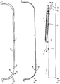
- a first embodiment of a telescopic conveyor is in Fig. 1 and 2 explained.
- the telescopic conveyor belt 2 has a base conveyor section 4, which may be formed, for example, by a machine frame, or the like, on support elements 6 such as feet, rollers, drive wheels. be on a ground or on it can be moved.
- a first telescopic conveyor section 8 is mounted in and out of retractable extension direction 7 and retractable, on which in turn a second telescopic conveyor section 10 is held extendable and retractable.
- On the base conveyor section 4 is a cross-sectionally substantially U-shaped, downwardly closed base guide trough 12 is held. Within and above the base guide trough 12, a first telescopic guide trough 14 is arranged, within which in turn a second telescopic guide trough 16 is arranged.
- each guide tray has a support region 20 which can be essentially planar and laterally directly, without clearance or longitudinal gap, elevated guide regions adjacent to the support region 22 has. All Leitwannen thus have over their full length a closed down trough shape, which reliably prevents falling out even small objects.
- An in Fig. 3 and 6 but not in Fig. 1 and 2 illustrated conveyor belt 26 is endlessly guided around the base conveyor section 4 and the telescopic conveyor sections 8, 10, as is well known in telescopic conveyors, with a disposed within the base conveyor section drive and a belt storage mechanism with which the change in length of the extended portions of Telescopic conveyor sections can be compensated.
- An upper run of the conveyor belt 26 extends on top of the base conveyor section 4 and the telescopic conveyor sections 8, 10, wherein the guide troughs 12, 14 and 16 between the conveyor belt 26 and the base conveyor section 4 and the first and second telescopic conveyor section 8, 10 are arranged.
- the top of the support portion 20 of the guide troughs 12, 14, 16 thus forms a bearing surface for a bottom or inside of the conveyor belt in the region of its upper run, while the guide portions 22 prevent slipping or falling individual pieces of goods from the conveyor belt.
- the telescopic conveyor 2 operates in a conveying direction 30, which is directed against the extension direction 7, wherein the upper run of the conveyor belt 26 moves in the conveying direction 30, so that, for example, a container located within range of the telescopic telescopic conveyor sections 8, 10th is, in the conveying direction 30 can be unloaded.
- the conveying direction is reversed, if necessary.
- the first telescopic guide trough 14 is coupled with its rear end 14a seen in the conveying direction 30 with the first telescopic conveyor section 8, in particular with its extension end 8a.
- the second telescopic guide trough 16 is coupled to the second telescoping conveyor section 10, and expediently with its extension end 10a.
- the length of the base guide trough 12 substantially corresponds to the length of the base conveyor section 4
- the length of the first telescopic guide trough 14 essentially corresponds to an extension path of the first telescopic conveyor section 8 and the length of the second telescope guide trough 16 substantially to one Extension path of the second telescopic conveyor section 10, it is ensured that in each extended position of the telescopic conveyor belt 2, the telescopic guide troughs 12, 14, 16 are at least partially overlapping each other and an uninterrupted support surface for the conveyor belt in the form of support portions 20 and a form gapless bottom and side guide for cargo in the form of the guide portions 22 and optionally the lateral edges of the support portions 20.
- Fig. 3 to 5 illustrate a first variant of the storage of the longitudinally displaceable guide vanes arranged one inside the other, wherein for the sake of simplicity, only the base guide trough 12 and the first telescopic guide trough 14 are shown.
- the in Fig. 3 to 7 can be basically any suitable and expedient form, for example, may be concave, and that the guide portions 22 may assume any suitable and expedient form, for example, vertically (in the vertical direction 32) may run, or be any angled or curved can.
- the guide troughs may be made of metal, plastic or a composite material.
- the under-and outside the first telescopic guide trough 14 arranged base guide trough 12 has a vertically upwardly freely ending guide region 22, on which a horizontal guide flange 22a is arranged.
- the upper and inside the base guide trough 12 arranged first telescopic guide trough 14, however, is provided at the upper end of its guide portion 22 with an inverted U-shaped guide profile 22b, which overlaps the guide portion 22 of the base guide trough 12 and arranged in pairs to the horizontal Rotary axes rotatable vertical guide rollers 34 and paired, rotatable about vertical axes of rotation horizontal guide rollers 36 are held.
- the horizontal guide rollers 36 run and prevent horizontal displacement of the two guide troughs 12, 14 relative to each other.
- Fig. 6 shows a variant of the leadership of the guide troughs by means of plastic rails 40 which are mounted on the underside of the first telescopic guide trough 14 and slide on the top or inside of the base guide trough 12.
- Fig. 7 shows plastic or other easily lubricious material existing guide troughs, which can be dispensed with separate guide elements such as rollers or plastic rails.
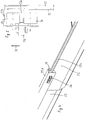
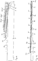
- FIG. 8 to 11 illustrate a second embodiment of a telescopic conveyor belt, wherein on the base conveyor section 4, an attachment 50 for increased assembly seen in the extension 7 rear end, or the telescopic conveyor sections 8, 10 facing away from the end 12 b of the base guide trough 12 is arranged so that the base guide trough 12 has a gradient opposite to the extension direction 7 or in the direction of the telescopic conveyor sections 8, 10.
- the attachment 50 serves, in particular, for the purpose of arranging the delivery end of the telescopic conveyor 2 formed by the front end 12b of the base guide trough 2 higher relative to the base conveyor section 4, so that a further conveyor can be placed underneath.
- Fig. 8 shows, in the retracted state, not only the base guide trough 12 but also the telescoped first and second telescopic guide troughs 14, 16, respectively a relative to the base conveyor section 4 and the extension direction 7 of the telescopic conveyor sections 8, 10 inclined position.
- each telescopic conveyor section 8, 10 is assigned not only a telescopic guide trough, but two guide troughs in the form of a coupled to the first telescopic conveyor section 8 first pullout guide trough 14 'and a with this coupled first follower guide trough 14 ", and in the form of a second pull-out guide trough 16 'coupled to the second telescopic conveyor section 10 and a second follower trough 16" coupled thereto.
- the follower trays 14 ", 16" are coupled to the pull-out guide troughs 14 ', 16' via a stop limiting stop.
- Each follow-up tray can be adjusted according to the extension ladder assigned to it Fig. 3 to 7 be stored.
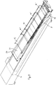
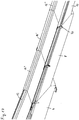
- FIGS. 12 and 13 show a third embodiment, which differs from the second embodiment 8 to 11 differs in that on each telescoping conveyor section 8, 10 not only an extract guide trough and coupled with this follower trough are present, but that each telescopic conveyor section three guide troughs are provided, namely on the first telescopic conveyor section 8 coupled thereto first pullout guide trough 14 ', a first follower trough 14 "coupled thereto and a further first follower trough 14"' coupled thereto, and on the second telescopic conveying section 10 a second pullout guide trough 16 'coupled thereto, one with this coupled second secondary side trough 16 "and in turn coupled to this another second secondary side trough 16"'. All follow-up trays are coupled with each other and with the respective pull-out guide trough via limiting stops, and they can be connected to the respective associated pull-out guide trough Fig. 3 to 7 be stored.
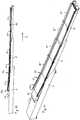
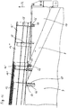
- FIGS. 14 and 15 show a fourth embodiment of a telescopic conveyor belt according to the invention, wherein in the region of the base conveyor section 4 additionally a wedge element 60 is provided.
- Fig. 14 shows the telescopic conveyor belt in the retracted position
- Fig. 15 shows the extended position.
- the wedge member 60 is between the base conveyor section 4 and with this coupled base guide trough 12 and connected to the first telescopic conveyor section 8.
- the wedge element 60 is thus displaced in the extension direction 7 relative to the base conveyor section 4 and the base guide trough 12 and passes, as Fig.
- first telescopic guide trough 14 shows, between the first telescopic guide trough 14 and the extended first telescopic conveyor section 8, so that the base guide trough 12 is raised relative to the base conveyor section 4.
- the telescopic conveyor belt according to the fourth embodiment in contrast to the second embodiment not only two, but three extendable telescopic conveyor sections, namely a first, relative to the base conveyor section 4 extendable and guided on this telescopic conveyor section 8, a second, relatively to the first telescopic conveyor section 8 extendable and guided on this telescopic conveyor section 10 and a third, relative to the second telescopic conveyor section 10 extendable and guided on this telescopic conveyor section 11.
- first telescopic Leit trough could be arranged, as in the first embodiment, are on it as in the second embodiment, a first pullout guide trough 14 'and coupled thereto first follower trough 14 "arranged, with a seen in the extension direction 7 front end of the first pullout guide trough 14' at an extension end 8a of the first Telescopic conveyor section 8 is held.
- a second extension guide trough 16 'and a second conveyor trough 16 "coupled thereto are arranged on the second telescopic conveyor section 10, wherein a front end seen in the extension direction 7 of the second pullout guide trough 16' with an extension end 10a of the second telescope
- a third separation guide trough 17 'and a third follower trough 17 "coupled thereto are arranged in a corresponding manner on the third part conveying section 11, a front end of the third separation guide trough 17' seen in the extension direction 7. is held on an extension end 11 a of the third telescopic conveying section 11.
- the wedge member 60 is thus after in the extended state Fig. 13 between the first telescopic conveyor section 8 and the first pull-out guide trough 14 'and the following guide trough 14 "and lifts them from the first telescopic conveyor section 8.
- the wedge element 60 has a sufficient length, so that it is in the extended state of the telescopic conveyor after Fig. 15 not only on the first telescopic conveyor section 8, but also partially on the base conveyor section 4, so that also the telescopic conveyor sections 8, 10 facing or viewed in the extension 7 front end 12a of the base guide trough 12 on the wedge element 60 is located and is lifted by this.
- the base guide trough can be fixedly attached to the base conveyor section 4, and the telescopic guide troughs 14, 16 can each be firmly connected to the telescopic conveyor sections 8, 10, since it is not necessarily to the height changes of the extension and retraction Telescopic guide tubes are coming. Nevertheless, it may be expedient if the first and second telescopic guide trough 14, 16 are mounted with vertical play on the telescopic conveyor sections 8, 10, so that seen in the extension direction 7 front ends of the telescopic guide troughs 14, 16, at the Ausfahrenden 8a, 10a are held, in the extended state ( Fig. 2 ) alslieiegen on the respective telescopic conveyor section.
- first telescopic guide trough 14 is located inside and on the base guide trough 12 and the second telescopic guide trough 16 is located inside and on the first telescopic guide trough 14, according to FIG Fig. 7 , or via guide elements according to Fig. 3 or Fig. 6 supported, which inevitably results in the extended state, a vertical distance between a telescopic conveyor section and a telescopic guide trough arranged above it, which is the greater, the more telescopic guide troughs are arranged one inside the other and the larger whose thickness dimensions are. Such a distance, however, is undesirable, but the guide troughs should rest on the telescopic conveyor sections.
- the telescopic guide troughs are held at their front end seen in the extension with vertical play on the telescopic conveyor sections, as in Fig. 16 is shown.
- a horizontal fastening bolt 64 is arranged, which engages in a vertically aligned slot 66 of a respective telescopic Leitwanne or pull-out guide trough 14 ', 16' and follower.
- front end of the extension guide troughs 14 ', 16' is on both sides of the respective telescopic conveyor section 8, 10 each mounted a mounting bracket 68 in which a slot 66 is introduced, so that a pivotable about a horizontal transverse axis and also height-adjustable coupling between a pull-out ladder and a telescoping conveyor section is made.
- the base guide trough 12 is supported with vertical play on the base conveyor section 4, which is also shown in FIG Fig. 16 is shown.
- the base guide trough 12 is raised or lowered relative to the base conveyor section 4, so that said vertical movement possibility is provided.
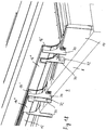
- first abstract limiting stops 70 which prevent an excessively broad excerpt of individual follow-up trays with respect to them leading extractive guide troughs.
- lateral guide elements 72 and support guide elements 74 with which individual follow-up trays are guided longitudinally displaceably on the telescopic conveyor section carrying them laterally and resting.
- Fig. 19 shows two lateral guide elements 72 and two support-guide elements 74 in cooperation with a second telescoping conveyor section 10 exemplified.
Description
Die Erfindung betrifft ein Teleskopförderband nach dem Oberbegriff des Anspruchs 1, wie es aus der
Ein ähnlicher Teleskopförderer ist aus der
Die Aufgabe der Erfindung besteht darin, ein Teleskopförderband mit einer seitlichen Führung für transportierte Gegenstände bereitzustellen, so dass diese nicht seitlich von dem Förderband herunterfallen können. Dabei wird eine kompakte und im eingefahrenen Zustand des Teleskopförderers platzsparende Bauweise angestrebt. Außerdem sollen Spalte, Öffnungen und Querschnittsverjüngungen vermieden werden, und es soll zuverlässig verhindert werden, dass kleinere Stückgutteile oder Teile davon, beispielsweise Bänder, Riemen, Schnallen o.ä., unter den Fördergurt gelangen können.The object of the invention is to provide a telescopic conveyor belt with a lateral guide for transported objects, so that they can not fall laterally from the conveyor belt. In this case, a compact and in the retracted state of the telescopic conveyor space-saving design is sought. In addition, gaps, openings and cross-sectional tapers should be avoided, and it should be reliably prevented that smaller piece goods or parts thereof, such as belts, straps, buckles, etc., can get under the conveyor belt.
Diese Aufgabe wird erfindungsgemäß durch ein Teleskopförderband nach Anspruch 1 gelöst.This object is achieved by a telescopic conveyor belt according to claim 1.
Es kann vorgesehen sein, dass der Tragbereich der Basis-Leitwanne unmittelbar an die Leitbereiche der Basis-Leitwanne anschließt oder mit diesen in voller Länge verbunden ist, so dass eine geschlossene Wannenform gebildet ist. Weiter kann vorgesehen sein, dass der Tragbereich der Teleskop-Leitwanne unmittelbar an die Leitbereiche der Teleskop-Leitwanne anschließt oder mit diesen in voller Länge verbunden ist, so dass eine geschossene Wannenform gebildet ist.It can be provided that the support region of the base guide trough directly adjoins the guide regions of the base guide trough or is connected to these in full length, so that a closed trough shape is formed. Furthermore, it can be provided that the support region of the telescopic guide trough directly adjoins the guide regions of the telescopic guide trough or is connected to these in full length, so that a closed trough shape is formed.
Relativ zu dem Basis-Förderabschnitt können mehrere aufeinanderfolgende Teleskop-Förderabschnitte in und entgegen der Ausfahrrichtung teleskopartig aus- und einfahrbar sein, insbesondere daran gehalten sein.Relative to the base conveyor section, a plurality of successive telescopic conveyor sections can be telescopically extendable and retractable in and against the extension direction, in particular held thereon.
Jedem Teleskop-Förderabschnitt kann eine Teleskop-Leitwanne zugeordnet sein, wobei ein dem Basis-Förderabschnitt abgekehrtes Ende einer jeden Teleskop-Leitwanne mit einem Ausfahrende des jeweiligen Teleskop-Förderabschnitts gekoppelt sein kann.Each telescopic conveyor section may be associated with a telescopic guide trough, wherein an end remote from the base conveyor section of each telescopic guide trough may be coupled to an extension end of the respective telescopic conveyor section.
Es kann vorgesehen sein, dass jedem Teleskop-Förderabschnitt mehrere Teleskop-Leitwannen zugeordnet sind, jeweils umfassend eine Auszugs-Leitwanne und mindestens eine damit gekoppelte Folgeleitwanne, wobei ein dem Basis-Förderabschnitt abgekehrtes Ende einer jeden Auszugs-Leitwanne mit einem Ausfahrende des jeweiligen TeleskopFörderabschnitts und ein dem Basis-Förderabschnitt zugekehrtes Ende einer jeden Auszugs-Leitwanne über einen auszugsbegrenzenden Anschlag mit einer Folgeleitwanne gekoppelt ist. Bei mehreren Folgeleitwannen je Teleskop-Förderabschnitt ist jede weitere Folgeleitwanne mit einer in Richtung auf die Auszugs-Leitwanne benachbarten Folgeleitwanne über einen auszugsbegrenzenden Anschlag gekoppelt.It can be provided that each telescopic conveying section are assigned a plurality of telescopic guide tubes, each comprising an extractive guide trough and at least one follower trough coupled thereto, one end remote from the base conveyor section of each extension guide trough having an extension end of the respective telescoping conveyor section and an end of each extension guide trough facing the base conveyor section is coupled to a follower trough via an outflow limiting stop. In the case of several follow-up trays per telescopic conveyor section, each further follow-up sump is coupled to a follow-up sump adjoining in the direction of the extension guide sump via an outflow limiting stop.
Bevorzugt ist vorgesehen, dass jede einzelne Leitwanne, ob Teleskop-Leitwanne, Auszugs-Leitwanne oder Folgeleitwanne, innerhalb der entgegen der Auszugsrichtung, oder in Richtung des Basis-Förderabschnitts gesehen, zunächstliegenden Leitwanne, ob Teleskop-Leitwanne, Auszugs-Leitwanne oder Folgeleitwanne, angeordnet ist, wobei die der Basis-Leitwanne benachbarte Leitwanne innerhalb der Basis-Leitwanne angeordnet ist. Eine solche Anordnung hat den Vorteil, dass bei einem Betrieb des Teleskopförderbands in einer bevorzugten Förderrichtung, wobei sich das Obertrum des Förderbands entgegen der Ausfahrrichtung oder anders gesagt von einem Ausfahrende des Teleskopförderers in Richtung auf den Basis-Förderabschnitt bewegt, keine Behinderung oder Verklemmwirkung der zwischen benachbarten Leitwannen gebildeten Stufen eintreten kann, da sich die Querschnittsabmessungen jeder einzelnen Leitwanne in Richtung auf die Basis-Leitwanne und damit in der bevorzugten Förderrichtung vergrößern und nicht verkleinern, was bei einer umgekehrten Anordnung der Fall wäre. Alle derartigen Teleskop-, Auszugs-, Folge- oder Basisleitwannen haben die oben beschriebene geschlossene Wannenform.It is preferably provided that each individual guide trough, whether telescopic guide trough, pull-out trough or follow-on trough, within the opposite direction to the extension, or in the direction As seen from the base conveyor section, the next leading trough, whether telescopic trough, pull-out trough or follow-on trough, is arranged, wherein the base trough adjacent trough is disposed within the base trough. Such an arrangement has the advantage that during operation of the telescopic conveyor belt in a preferred conveying direction, wherein the upper strand of the conveyor belt moves against the extension direction or in other words from an extension end of the telescopic conveyor in the direction of the base conveyor section, no obstruction or Verklemmwirkung between formed adjacent guide troughs can occur as the cross-sectional dimensions of each guide trough in the direction of the base guide trough and thus in the preferred direction of conveyance increase and not shrink, which would be the case with a reverse arrangement. All such telescopic, pull-out, follow-up or base guide troughs have the closed trough shape described above.
Bevorzugt beträgt ein Höhenunterschied zwischen zwei benachbarten Leitwannen nicht mehr als das 2fache, 1,5fache oder 1fache einer Materialdicke des Tragbereichs der aufliegenden Leitwanne. Tragbereiche benachbarter Leitwannen können somit unmittelbar oder mit geringem Abstand aufeinanderliegen. Dadurch ergibt sich eine praktisch ebene Förderfläche, da die Materialdicke der Tragbereiche im Verhältnis zu deren Länge sehr klein ist, beispielsweise 5 - 20mm bei einer Länge von bis zu 1 m, 2 m, 3 m oder mehr.Preferably, a height difference between two adjacent guide troughs is not more than 2 times, 1.5 times or 1 times a material thickness of the support region of the overlying guide trough. Supporting areas of adjacent guide troughs can thus lie on one another directly or at a small distance. This results in a practically flat conveying surface, since the material thickness of the support areas in relation to their length is very small, for example 5 - 20mm at a length of up to 1 m, 2 m, 3 m or more.
Es kann vorgesehen sein, dass die Tragbereiche benachbarter Leitwannen im voll ausgefahrenen Zustand in gleicher Höhe liegen. Dies kann dadurch erreicht werden, dass ein Ausfahrende eines Teleskop-Förderabschnitts mit Vertikalspiel mit einem dem Basis-Förderabschnitt zugekehrten Ende der oder einer Teleskop-Leitwanne oder einer Auszugs-Leitwanne gekoppelt ist. Hierfür kann an der Teleskop-Leitwanne oder an jeder Auszugs-Leitwanne ein vertikales Langloch und an dem Ausfahrende ein das Langloch durchgreifender Befestigungsbolzen angeordnet sein, oder umgekehrt.It can be provided that the support areas of adjacent guide troughs in the fully extended state are at the same height. This can be achieved by coupling an extension end of a telescoping conveying section with vertical clearance to an end of the or a telescopic guide trough or a pull-out guide trough facing the base conveyor section. For this purpose, a vertical slot can be arranged on the telescopic guide trough or on each pullout guide trough and on the extension end a fastening bolt passing through the slot, or vice versa.
Es kann vorgesehen sein, dass die Teleskop-Leitwanne mittels Führungselementen wie Rollen oder Gleitstücken an der Basis-Leitwanne längsverschieblich geführt ist. Entsprechend kann die oder jede Auszugs-Leitwanne mittels Führungselementen wie Rollen oder Gleitstücken an einer damit gekoppelten Folgeleitwanne längsverschieblich geführt sein.It can be provided that the telescopic guide trough is guided longitudinally displaceable by means of guide elements such as rollers or sliders on the base guide trough. Accordingly, the or each pullout guide trough can be guided by means of guide elements such as rollers or sliders on a follow-up trough coupled thereto so as to be longitudinally displaceable.
Die Erfindung wird nachfolgend anhand mehrerer Ausführungsbeispiele unter Bezugnahme auf eine Zeichnung erläutert, wobei die erste, zweite und dritte Ausführungsformen nicht Teil der Erfindung sind, und wobei
-
Fig. 1 eine Seitenansicht einer ersten Ausführungsform eines Teleskopförderbands im eingefahrenen Zustand zeigt, -
Fig. 2 das Teleskopförderband nachFig. 1 im ausgefahrenen Zustand zeigt, -
Fig. 3 eine Querschnittsansicht einer Teleskop-Leitwanne und einer daran mittels Rollen längsverschieblich geführten Folgeleitwanne zeigt, -
Fig. 4 eine perspektivische Ansicht eines Übergangsbereichs zwischen einer Teleskop-Leitwanne und einer mittels Rollen daran längsverschieblich geführten Folgeleitwanne zeigt, -
Fig. 5 eine vergrößerte Darstellung des inFig. 3 mit A bezeichneten Bereichs zeigt, -
Fig. 6 eine Ansicht entsprechendFig. 3 für eine Lagerung mittels Kunststoffschienen als Führungselemente zeigt, -
Fig. 7 eine Ansicht entsprechendFig. 6 ohne Führungselemente zeigt, -
Fig. 8 eine Seitenansicht einer zweiten Ausführungsform eines Teleskopförderers im eingefahrenen Zustand zeigt, -
Fig. 9 eine perspektivische Ansicht des Förderers nachFig. 8 zeigt, -
Fig. 10 eine Seitenansicht des Förderers nachFig. 8 und9 im ausgefahrenen Zustand zeigt, -
Fig. 11 eine perspektivische Ansicht des Förderers nachFig. 10 zeigt, -
Fig. 12 eine Seitenansicht einer dritten Ausführungsform eines Teleskopförderers im ausgefahrenen Zustand zeigt, -
Fig. 13 eine perspektivische Ansicht des Teleskopförderers nachFig. 12 zeigt, -
Fig. 14 eine Seitenansicht einer Ausführungsform eines erfindungsgemäßen Teleskopförderers im eingefahrenen Zustand zeigt, -
Fig. 15 eine Seitenansicht des Förderers nachFig. 14 im ausgefahrenen Zustand zeigt, -
Fig. 16 die Kopplung der Basis-Leitwanne an den Basis-Förderabschnitt und die Kopplung der Auszugs-Leitwannen an die jeweiligen Teleskop-Förderabschnitte mittels Befestigungsbolzen und Langlöchern beispielhaft anhand der zweiten Ausführungsform zeigt, und -
Fig. 17 - 19 Anschlag- und Führungselemente in einer perspektivischen Ansicht, einer vergrößerten Darstellung und einer Querschnittsansicht beispielhaft anhand der zweiten Ausführungsform zeigen.
-
Fig. 1 shows a side view of a first embodiment of a telescopic conveyor belt in the retracted state, -
Fig. 2 after the telescopic conveyor beltFig. 1 in the extended state shows -
Fig. 3 shows a cross-sectional view of a telescopic guide trough and a longitudinally guided by means of rollers longitudinal follow-up trough, -
Fig. 4 3 shows a perspective view of a transitional area between a telescopic guide trough and a follower trough guided longitudinally displaceably by means of rollers, -
Fig. 5 an enlarged view of the inFig. 3 area indicated by A, -
Fig. 6 a view accordinglyFig. 3 for storage by means of plastic rails as guide elements, -
Fig. 7 a view accordinglyFig. 6 without guide elements, -
Fig. 8 shows a side view of a second embodiment of a telescopic conveyor in the retracted state, -
Fig. 9 a perspective view of the conveyor afterFig. 8 shows, -
Fig. 10 a side view of the conveyor afterFig. 8 and9 in the extended state shows -
Fig. 11 a perspective view of the conveyor afterFig. 10 shows, -
Fig. 12 shows a side view of a third embodiment of a telescopic conveyor in the extended state, -
Fig. 13 a perspective view of the telescopic conveyor afterFig. 12 shows, -
Fig. 14 shows a side view of an embodiment of a telescopic conveyor according to the invention in the retracted state, -
Fig. 15 a side view of the conveyor afterFig. 14 in the extended state shows -
Fig. 16 the coupling of the base guide trough to the base conveyor section and the coupling of the extension guide troughs to the respective telescopic conveyor sections by means of fastening bolts and oblong holes exemplified by the second embodiment, and -
Fig. 17 - 19 Show stop and guide elements in a perspective view, an enlarged view and a cross-sectional view by way of example with reference to the second embodiment.
Eine erste Ausführungsform eines Teleskopförderers ist in
Die Querschnittsformen der Basis- und Teleskop-Leitwannen 12, 14 und 16 ergeben sich aus
Ein in
Die Oberseite des Tragbereichs 20 der Leitwannen 12, 14, 16 bildet somit eine Auflagefläche für eine Unterseite bzw. Innenseite des Fördergurts im Bereich seines Obertrums, während die Leitbereiche 22 ein Abgleiten oder Herunterfallen einzelner Stückgüter von dem Fördergurt verhindern.The top of the
Im regulären Betrieb arbeitet der Teleskopförderer 2 in einer Förderrichtung 30, die entgegen der Ausfahrrichtung 7 gerichtet ist, wobei sich das Obertrum des Fördergurts 26 in Förderrichtung 30 bewegt, so dass beispielsweise ein Container, der sich in Reichweite der ausfahrbaren Teleskop-Förderabschnitte 8, 10 befindet, in Förderrichtung 30 entladen werden kann. Selbstverständlich kann vorgesehen sein, dass die Förderrichtung bedarfsweise umgekehrt wird.In normal operation, the
Während die Basis-Leitwanne 12 an dem Basis-Förderabschnitt 4 gehalten oder befestigt ist, ist die erste Teleskop-Leitwanne 14 mit ihrem in Förderrichtung 30 gesehen hinteren Ende 14a mit dem ersten Teleskop-Förderabschnitt 8 gekoppelt, insbesondere mit dessen Ausfahrende 8a. In entsprechender Weise ist die zweite Teleskop-Leitwanne 16 mit ihrem in Förderrichtung 30 gesehen hinteren Ende 16a mit dem zweiten Teleskop-Förderabschnitt 10 gekoppelt, und zwar zweckmäßigerweise mit dessen Ausfahrende 10a.While the
Da die Länge der Basis-Leitwanne 12 im Wesentlichen der Länge des Basis-Förderabschnitts 4 entspricht, die Länge der ersten Teleskop-Leitwanne 14 im Wesentlichen einem Ausfahrweg des ersten Teleskop-Förderabschnitts 8 entspricht und die Länge der zweiten Teleskop-Leitwanne 16 im Wesentlichen einem Ausfahrweg des zweiten Teleskop-Förderabschnitts 10 entspricht, ist sichergestellt, dass in jeder Ausfahrstellung des Teleskop-Förderbands 2 die Teleskop-Leitwannen 12, 14, 16 wenigstens teilweise einander überlappend angeordnet sind und eine ununterbrochene Abstützfläche für den Fördergurt in Form der Tragbereiche 20 und eine lückenlose untere und seitliche Führung für Stückgüter in Form der Leitbereiche 22 und gegebenenfalls der seitlichen Ränder der Tragbereiche 20 bilden.Since the length of the
Wie
Wie
Bei der in
Das Teleskopförderband nach der vierten Ausführungsform verfügt im Unterschied zur zweiten Ausführungsform nicht nur über zwei, sondern über drei ausfahrbare Teleskop-Förderabschnitte, nämlich einen ersten, relativ zu dem Basis-Förderabschnitt 4 ausfahrbaren und an diesem geführten Teleskop-Förderabschnitt 8, einen zweiten, relativ zu dem ersten Teleskop-Förderabschnitt 8 ausfahrbaren und an diesem geführten Teleskop-Förderabschnitt 10 und einen dritten, relativ zu dem zweiten Teleskop-Förderabschnitt 10 ausfahrbaren und an diesem geführten Teleskop-Förderabschnitt 11. Obwohl auf dem ersten Teleskop-Förderabschnitt 8 eine erste Teleskop-Leitwanne angeordnet sein könnte, wie bei der ersten Ausführungsform, sind darauf wie bei der zweiten Ausführungsform eine erste Auszugs-Leitwanne 14' und eine damit gekoppelte erste Folgeleitwanne 14" angeordnet, wobei ein in Ausfahrrichtung 7 gesehen vorderes Ende der ersten Auszugs-Leitwanne 14' an einem Ausfahrende 8a des ersten Teleskop-Förderabschnitts 8 gehalten ist. In entsprechender Weise sind auf dem zweiten Teleskop-Förderabschnitt 10 eine zweite Auszugs-Leitwanne 16' und eine damit gekoppelte zweite Förderleitwanne 16" angeordnet, wobei ein in Ausfahrrichtung 7 gesehen vorderes Ende der zweiten Auszugs-Leitwanne 16' mit einem Ausfahrende 10a des zweiten Teleskop-Förderabschnitts 10 gekoppelt ist. Weiterhin sind in entsprechender Weise auf dem dritten Teil-Förderabschnitt 11 eine dritte Auszugs-Leitwanne 17' und eine damit gekoppelte dritte Folgeleitwanne 17" angeordnet, wobei ein in Ausfahrrichtung 7 gesehen vorderes Ende der dritten Auszugs-Leitwanne 17' an einem Ausfahrende 11a des dritten Teleskop-Förderabschnitts 11 gehalten ist.The telescopic conveyor belt according to the fourth embodiment, in contrast to the second embodiment not only two, but three extendable telescopic conveyor sections, namely a first, relative to the
Das Keilelement 60 befindet sich somit im ausgezogenen Zustand nach
Das Keilelement 60 hat eine ausreichende Länge, so dass es sich im ausgefahrenen Zustand des Teleskopförderbands nach
Bei der ersten Ausführungsform nach
Um eine solche Auflage der Teleskop-Leitwannen auf den Teleskop-Förderabschnitten zu ermöglichen, sind die Teleskop-Leitwannen an ihren in Ausfahrrichtung gesehen vorderen Ende mit Vertikalspiel an den Teleskop-Förderabschnitten gehalten, wie in
In entsprechender Weise ist bei der dritten Ausführungsform, bei der ein Keilelement 60 vorgesehen ist, die Basis-Leitwanne 12 mit Vertikalspiel an dem Basis-Förderabschnitt 4 gehalten, was ebenfalls in
- 22
- TeleskopförderbandTelescopic conveyor belt
- 44
- Basis-FörderabschnittBase conveyor section
- 66
- Tragelementsupporting member
- 77
- Ausfahrrichtungof extension
- 88th
- erster Teleskop-Förderabschnittfirst telescopic conveyor section
- 8a8a
- Ausfahrendedriving out
- 1010
- zweiter Teleskop-Förderabschnittsecond telescopic conveyor section
- 10a10a
- Ausfahrendedriving out
- 1111
- dritter Teleskop-Förderabschnittthird telescopic conveyor section
- 11a11a
- Ausfahrendedriving out
- 1212
- Basis-LeitwanneBasic Leitwanne
- 12a12a
- hinteres Enderear end
- 12b12b
- vorderes Endefront end
- 1414
- erste Teleskop-Leitwannefirst telescopic ladder
- 14a14a
- hinteres Enderear end
- 14'14 '
- erste Auszugs-Leitwannefirst pull-out ladder
- 14"14 "
- erste Folgeleitwannefirst follow-up tub
- 14"'14 " '
- weitere erste Folgeleitwanneanother first follow-up tray
- 1616
- zweite Teleskop-Leitwannesecond telescopic ladder
- 16a16a
- hinteres Enderear end
- 16'16 '
- zweite Auszugs-Leitwannesecond pull-out ladder
- 16"16 "
- zweite Folgeleitwannesecond follow-up tray
- 16'"16 ''
- weitere zweite Folgeleitwanneanother second follow-up tray
- 17'17 '
- dritte Auszugs-Leitwannethird pull-out ladder
- 17"17 "
- dritte Folgeleitwannethird follow-up tray
- 2020
- Tragbereichsupport area
- 2222
- Leitbereichconducting region
- 22a22a
- Führungsflanschguide flange
- 22b22b
- Führungsprofilguide profile
- 2626
- Förderbandconveyor belt
- 3030
- Förderrichtungconveying direction
- 3232
- Vertikalrichtungvertical direction
- 3434
- VertikalführungsrolleVertical leadership
- 3636
- HorizontalführungsrolleHorizontal leadership
- 4040
- Kunststoffschiene (Gleitstück)Plastic rail (slider)
- 5050
- Aufsatzessay
- 6060
- Keilelementkey member
- 6464
- Befestigungsbolzenmounting bolts
- 6666
- LanglochLong hole
- 6868
- Montagewinkelmounting Brackets
- 7070
- auszugsbegrenzender Anschlagabstract limiting stop
- 7272
- seitliches Führungselementlateral guide element
- 7474
- Trag-FührungselementSupport guide member
Claims (8)
- Telescopic conveyor belt (2), with a base conveyor section (4), a telescopic conveyor section (8) which is held on the base conveyor section (4) and which can be extended and retracted telescopically, in and counter to a direction of extension (7), relative to the base conveyor section (4), an endlessly circulating conveyor belt (26) which forms a conveyor surface and which, with its carrying run, is led along an upper surface of the base conveyor section (4) and of the telescopic conveyor section (8), a base guide trough (12) which is closed on the underside and which is arranged between the conveyor belt (26) and the base conveyor section (4) and which has a carrying area (20) for accommodating the conveyor belt (26) and has raised guide areas (22) following on laterally from the carrying area (20), and a telescopic guide trough (14) which is closed on the underside and is arranged between the conveyor belt (26) and the telescopic conveyor section (8) and has a carrying area (20) for accommodating the conveyor belt (26) and has raised guide areas (22) following on laterally from the carrying area (20),
wherein the base guide trough (12) is coupled to the base conveyor section (4) and the telescopic guide trough (14) is coupled to an extension end (8a) of the telescopic conveyor section (8),
wherein the telescopic guide trough (14) can be extended and retracted telescopically relative to the base guide trough (12), and
wherein the telescopic conveyor belt (2) is adjustable between a nested position, in which the telescopic conveyor section (8) is driven in relative to the base conveyor section (4) and the telescopic guide trough (14) is driven in telescopically relative to the base guide trough (12), and an extended position in which the telescopic conveyor section (8) is extended at least partially relative to the base conveyor section (4) and the telescopic guide trough (14) is extended at least partially relative to the base guide trough (12), characterised in that arranged on the fastening conveyor section (4) is a cap (50) for the raised installation of an end (12b) of the base guide trough (12) facing away from the telescopic conveyor section (8), with the base guide trough (12) having a slope in the direction of the telescopic conveyor section (8), and that on the base conveyor section (4), a wedge element (60) is held such that it can be moved in and counter to the direction of conveyance and is coupled to the or a telescopic conveyor section (8), wherein in the retracted position the base guide trough (12), with its end (12a) facing the telescopic conveyor section, rests on a starting area of the wedge element (60) at a first height above or immediately on the base conveyor section (4), and in the extended position the base guide trough (12), with its end (12a) facing the telescopic conveyor section (8), rests on an end area of the wedge element (60) at a second height above the base conveyor section (4), wherein the second height is greater than the first height. - Telescopic conveyor belt according to claim 1, characterised in that several consecutive telescopic conveyor sections (8, 10, 11) can be extended and retracted telescopically relative to the base conveyor section (4), in and counter to the direction of extension (7).
- Telescopic conveyor belt according to claim 1 or 2, characterised in that assigned to each telescopic conveyor section (8, 10, 11) is a telescopic guide trough (14, 16, 17', 17"), with an end of each telescopic guide trough facing away from the base conveyor section (4) being coupled to an extension end (8a, 10a, 11 a) of the respective telescopic conveyor section (8, 10, 11).
- Telescopic conveyor belt according to one of the preceding claims, characterised in that each telescopic conveyor section (8,10,11) is assigned several telescopic guide troughs, respectively comprising a pull-out guide trough (14', 16', 17') and at least one sequential guide trough (14", 16", 17") coupled to it, with an end of each pull-out guide trough facing away from the base conveyor section (4) being coupled to an extension end (8a, 10a, 11a) of the respective telescopic conveyor section and an end of each pull-out guide trough facing the base conveyor section (4) being coupled to a sequential guide trough via a limit stop that limits extension.
- Telescopic conveyor belt according to one of the preceding claims, characterised in that an extension end (8a, 10a, 11a) of a telescopic conveyor section (8, 10, 11) is coupled, with vertical play, to an end of a telescopic guide trough (14, 16) or a pull-out guide trough (14', 16', 17') facing away from the base conveyor section.
- Telescopic conveyor belt according to claim 5, characterised in that a vertical slot (66) is arranged on the telescopic guide trough (14, 16) or on each pull-out guide trough (14', 16', 17') and a fastening bolt (64) that engages through the slot (66) is arranged on the extension end (8a, 10a, 11a) of each telescopic conveyor section (8, 10, 11), or
- Telescopic conveyor belt according to one of the preceding claims, characterised in that the telescopic guide trough (14) is held on the base guide trough (12) such that it can be moved longitudinally by means of guide elements such as rollers (34, 36) or slide pieces (40).
- Telescopic conveyor belt according to one of the preceding claims, characterised in that the or each pull-out guide trough (14', 16', 17') held on a sequential guide trough (14", 16", 17") that is coupled to it such that it can be moved longitudinally by means of guide elements such as rollers (34, 36) or slide pieces (40).
Applications Claiming Priority (1)
| Application Number | Priority Date | Filing Date | Title |
|---|---|---|---|
| DE102013018063.5A DE102013018063A1 (en) | 2013-11-28 | 2013-11-28 | Telescopic conveyor belt |
Publications (2)
| Publication Number | Publication Date |
|---|---|
| EP2878554A1 EP2878554A1 (en) | 2015-06-03 |
| EP2878554B1 true EP2878554B1 (en) | 2017-02-01 |
Family
ID=51900691
Family Applications (1)
| Application Number | Title | Priority Date | Filing Date |
|---|---|---|---|
| EP14003806.8A Active EP2878554B1 (en) | 2013-11-28 | 2014-11-12 | Telescopic conveyor belt |
Country Status (6)
| Country | Link |
|---|---|
| US (1) | US9187249B2 (en) |
| EP (1) | EP2878554B1 (en) |
| DE (1) | DE102013018063A1 (en) |
| DK (1) | DK2878554T3 (en) |
| ES (1) | ES2623893T3 (en) |
| LT (1) | LT2878554T (en) |
Families Citing this family (9)
| Publication number | Priority date | Publication date | Assignee | Title |
|---|---|---|---|---|
| CN106364856B (en) * | 2016-08-30 | 2018-11-20 | 湖北华舟重工应急装备股份有限公司 | Mobile long range material casting system and method |
| US10435246B2 (en) * | 2017-08-30 | 2019-10-08 | Rite-Hite Holding Corporation | Extendible fences for extendible conveyors |
| WO2019090258A1 (en) * | 2017-11-03 | 2019-05-09 | Superior Industries, Inc. | Conveyor truss elevation apparatus, systems, and methods |
| WO2019178261A1 (en) * | 2018-03-13 | 2019-09-19 | Fast Global Solutions, Inc. | Scissor-extend conveyor |
| CN109305510A (en) * | 2018-11-16 | 2019-02-05 | 江苏锐特自控科技有限公司 | A kind of scalable conveyer belt access bridge |
| CN110589398A (en) * | 2019-09-27 | 2019-12-20 | 上海双彩吉智能科技有限公司 | Side plate structure for two-section telescopic machine |
| US10968044B1 (en) * | 2020-02-06 | 2021-04-06 | Transnorm System Gmbh | Conveying systems and drop link components |
| GB2601198B (en) * | 2020-11-24 | 2024-01-03 | Terex Gb Ltd | Foldable conveyor with deployable skirting |
| CN114287363B (en) * | 2021-12-28 | 2023-04-18 | 山东凤祥股份有限公司 | Telescopic transmission device and using method |
Family Cites Families (17)
| Publication number | Priority date | Publication date | Assignee | Title |
|---|---|---|---|---|
| US1967921A (en) * | 1933-07-18 | 1934-07-24 | Patrick H Burnell | Conveyer |
| US2032428A (en) * | 1934-04-18 | 1936-03-03 | Timothy F Mccarthy | Shaker conveyer trough |
| US2166447A (en) * | 1937-12-27 | 1939-07-18 | Gen Conveyors Corp | Belt conveyer |
| US3127978A (en) | 1960-06-27 | 1964-04-07 | T W & C B Sheridan Co | Telescoping loading conveyor |
| DE2254756A1 (en) * | 1971-12-21 | 1973-07-05 | Magdeburg Foerderanlagen | BELT CONVEYOR |
| US3835980A (en) * | 1973-03-20 | 1974-09-17 | Mc Donald J | Conveyor with extendible booms |
| NL7604753A (en) * | 1976-05-04 | 1977-11-08 | Miedema Landbouwwerktuigen | MOBILE BELT CONVEYOR. |
| US4711334A (en) * | 1986-08-28 | 1987-12-08 | Barry Joseph A | Telescopic chute for mixer discharge |
| DE4006474A1 (en) * | 1990-03-02 | 1991-09-05 | Caljan Ingenioerfirma & Maskin | Belt conveyor with support framework - has at least one deflector and drive drum, with continuous conveyor belt and telescopic section |
| US5351809A (en) * | 1993-04-26 | 1994-10-04 | Rapistan Demag Corporation | Multiple-stage extendable conveyor |
| DK0808290T3 (en) * | 1995-02-13 | 1999-08-30 | United Parcel Service Inc | Apparatus and method for transporting material |
| US6481563B1 (en) * | 1999-12-29 | 2002-11-19 | Rapistan Systems Advertising Corp. | Extendable conveyor with additional boom section |
| US6345950B1 (en) * | 2000-03-03 | 2002-02-12 | William Gerwitz | Telescoping ramp comprised of modular units |
| EP1559667A1 (en) * | 2004-01-30 | 2005-08-03 | Caljan Rite-Hite ApS | Telescopic belt conveyor |
| EP1559668B1 (en) | 2004-01-30 | 2007-07-25 | Caljan Rite-Hite ApS | Telescopic belt conveyor |
| WO2006068443A1 (en) * | 2004-12-22 | 2006-06-29 | Loteco, Inc. | Telescopic conveyor |
| DE102010005267A1 (en) * | 2010-01-20 | 2011-07-21 | nobab gmbh, 70825 | Conveying device for use with attachment device for packaged goods distribution system for packaged goods, has conveying head which has receiving area for manual placing of packaged goods |
-
2013
- 2013-11-28 DE DE102013018063.5A patent/DE102013018063A1/en not_active Withdrawn
-
2014
- 2014-11-12 EP EP14003806.8A patent/EP2878554B1/en active Active
- 2014-11-12 LT LTEP14003806.8T patent/LT2878554T/en unknown
- 2014-11-12 DK DK14003806.8T patent/DK2878554T3/en active
- 2014-11-12 ES ES14003806.8T patent/ES2623893T3/en active Active
- 2014-11-28 US US14/555,750 patent/US9187249B2/en active Active
Non-Patent Citations (1)
| Title |
|---|
| None * |
Also Published As
| Publication number | Publication date |
|---|---|
| LT2878554T (en) | 2017-04-10 |
| ES2623893T3 (en) | 2017-07-12 |
| DE102013018063A1 (en) | 2015-05-28 |
| US9187249B2 (en) | 2015-11-17 |
| DK2878554T3 (en) | 2017-05-15 |
| US20150144465A1 (en) | 2015-05-28 |
| EP2878554A1 (en) | 2015-06-03 |
Similar Documents
| Publication | Publication Date | Title |
|---|---|---|
| EP2878554B1 (en) | Telescopic conveyor belt | |
| DE4305190B4 (en) | Reach truck | |
| AT512934B1 (en) | drawer | |
| DE2425769A1 (en) | CONVEYOR DEVICE FOR LUGGAGE PIECES | |
| AT518049B1 (en) | drawer arrangement | |
| DE3408080A1 (en) | MOUNTING PIT COVER | |
| EP3728083B1 (en) | Teleskpic conveyor | |
| EP2998249A1 (en) | Conveyor device for conveying objects | |
| DE3432497A1 (en) | DEVICE FOR OPENING THE SLIDING DOORS OF A FURNITURE | |
| EP2944511B1 (en) | Storage compartment body comprising a sliding wall and vehicle comprising such a storage compartment body | |
| EP2042463B1 (en) | Telescopic apron for an elevator car and elevator car equipped with such a telescopic apron | |
| CH644426A5 (en) | MOUNTING PIT COVER. | |
| DE102013003587B4 (en) | Outfeed device for use in a conveyor system, discharge module for use in a conveyor system and conveyor system | |
| EP3235765A1 (en) | Unloading station of a conveying device and conveying device | |
| AT510903A2 (en) | DEVICE FOR ADJUSTING A FRONT PANEL | |
| DE3915074A1 (en) | C-CONVEYOR | |
| DE3913019A1 (en) | CHIP FEEDER | |
| DE202004011076U1 (en) | Work platform, especially for trains, has retractable drawer which can form extension of platform work surface | |
| DE2918007A1 (en) | CONVEYOR CHANNEL FOR A SCRATCH CHAIN CONVEYOR TO BE USED WITH A PITCHING MACHINE | |
| AT410629B (en) | TELESCOPE CABINET EXCERPT | |
| EP1484267B1 (en) | Accumulating conveyor with carrier | |
| WO2011124453A1 (en) | Device for adjusting the inclination of a front panel | |
| DE202014006378U1 (en) | Guide device for guiding a relative to a furniture body movable furniture part | |
| EP0277601B1 (en) | Supporting and pull-out device | |
| EP3756959B1 (en) | Height-adjustable switching cam |
Legal Events
| Date | Code | Title | Description |
|---|---|---|---|
| PUAI | Public reference made under article 153(3) epc to a published international application that has entered the european phase |
Free format text: ORIGINAL CODE: 0009012 |
|
| 17P | Request for examination filed |
Effective date: 20141112 |
|
| AK | Designated contracting states |
Kind code of ref document: A1 Designated state(s): AL AT BE BG CH CY CZ DE DK EE ES FI FR GB GR HR HU IE IS IT LI LT LU LV MC MK MT NL NO PL PT RO RS SE SI SK SM TR |
|
| AX | Request for extension of the european patent |
Extension state: BA ME |
|
| R17P | Request for examination filed (corrected) |
Effective date: 20150901 |
|
| RBV | Designated contracting states (corrected) |
Designated state(s): AL AT BE BG CH CY CZ DE DK EE ES FI FR GB GR HR HU IE IS IT LI LT LU LV MC MK MT NL NO PL PT RO RS SE SI SK SM TR |
|
| 17Q | First examination report despatched |
Effective date: 20160120 |
|
| GRAP | Despatch of communication of intention to grant a patent |
Free format text: ORIGINAL CODE: EPIDOSNIGR1 |
|
| INTG | Intention to grant announced |
Effective date: 20161028 |
|
| GRAS | Grant fee paid |
Free format text: ORIGINAL CODE: EPIDOSNIGR3 |
|
| GRAA | (expected) grant |
Free format text: ORIGINAL CODE: 0009210 |
|
| AK | Designated contracting states |
Kind code of ref document: B1 Designated state(s): AL AT BE BG CH CY CZ DE DK EE ES FI FR GB GR HR HU IE IS IT LI LT LU LV MC MK MT NL NO PL PT RO RS SE SI SK SM TR |
|
| REG | Reference to a national code |
Ref country code: GB Ref legal event code: FG4D Free format text: NOT ENGLISH |
|
| REG | Reference to a national code |
Ref country code: CH Ref legal event code: EP Ref country code: AT Ref legal event code: REF Ref document number: 865374 Country of ref document: AT Kind code of ref document: T Effective date: 20170215 |
|
| REG | Reference to a national code |
Ref country code: IE Ref legal event code: FG4D Free format text: LANGUAGE OF EP DOCUMENT: GERMAN |
|
| REG | Reference to a national code |
Ref country code: DE Ref legal event code: R096 Ref document number: 502014002571 Country of ref document: DE |
|
| REG | Reference to a national code |
Ref country code: NL Ref legal event code: FP |
|
| REG | Reference to a national code |
Ref country code: DK Ref legal event code: T3 Effective date: 20170510 |
|
| REG | Reference to a national code |
Ref country code: ES Ref legal event code: FG2A Ref document number: 2623893 Country of ref document: ES Kind code of ref document: T3 Effective date: 20170712 |
|
| PG25 | Lapsed in a contracting state [announced via postgrant information from national office to epo] |
Ref country code: HR Free format text: LAPSE BECAUSE OF FAILURE TO SUBMIT A TRANSLATION OF THE DESCRIPTION OR TO PAY THE FEE WITHIN THE PRESCRIBED TIME-LIMIT Effective date: 20170201 Ref country code: GR Free format text: LAPSE BECAUSE OF FAILURE TO SUBMIT A TRANSLATION OF THE DESCRIPTION OR TO PAY THE FEE WITHIN THE PRESCRIBED TIME-LIMIT Effective date: 20170502 Ref country code: IS Free format text: LAPSE BECAUSE OF FAILURE TO SUBMIT A TRANSLATION OF THE DESCRIPTION OR TO PAY THE FEE WITHIN THE PRESCRIBED TIME-LIMIT Effective date: 20170601 Ref country code: NO Free format text: LAPSE BECAUSE OF FAILURE TO SUBMIT A TRANSLATION OF THE DESCRIPTION OR TO PAY THE FEE WITHIN THE PRESCRIBED TIME-LIMIT Effective date: 20170501 Ref country code: FI Free format text: LAPSE BECAUSE OF FAILURE TO SUBMIT A TRANSLATION OF THE DESCRIPTION OR TO PAY THE FEE WITHIN THE PRESCRIBED TIME-LIMIT Effective date: 20170201 |
|
| PG25 | Lapsed in a contracting state [announced via postgrant information from national office to epo] |
Ref country code: PL Free format text: LAPSE BECAUSE OF FAILURE TO SUBMIT A TRANSLATION OF THE DESCRIPTION OR TO PAY THE FEE WITHIN THE PRESCRIBED TIME-LIMIT Effective date: 20170201 Ref country code: PT Free format text: LAPSE BECAUSE OF FAILURE TO SUBMIT A TRANSLATION OF THE DESCRIPTION OR TO PAY THE FEE WITHIN THE PRESCRIBED TIME-LIMIT Effective date: 20170601 Ref country code: BG Free format text: LAPSE BECAUSE OF FAILURE TO SUBMIT A TRANSLATION OF THE DESCRIPTION OR TO PAY THE FEE WITHIN THE PRESCRIBED TIME-LIMIT Effective date: 20170501 Ref country code: SE Free format text: LAPSE BECAUSE OF FAILURE TO SUBMIT A TRANSLATION OF THE DESCRIPTION OR TO PAY THE FEE WITHIN THE PRESCRIBED TIME-LIMIT Effective date: 20170201 Ref country code: RS Free format text: LAPSE BECAUSE OF FAILURE TO SUBMIT A TRANSLATION OF THE DESCRIPTION OR TO PAY THE FEE WITHIN THE PRESCRIBED TIME-LIMIT Effective date: 20170201 Ref country code: LV Free format text: LAPSE BECAUSE OF FAILURE TO SUBMIT A TRANSLATION OF THE DESCRIPTION OR TO PAY THE FEE WITHIN THE PRESCRIBED TIME-LIMIT Effective date: 20170201 |
|
| PG25 | Lapsed in a contracting state [announced via postgrant information from national office to epo] |
Ref country code: EE Free format text: LAPSE BECAUSE OF FAILURE TO SUBMIT A TRANSLATION OF THE DESCRIPTION OR TO PAY THE FEE WITHIN THE PRESCRIBED TIME-LIMIT Effective date: 20170201 Ref country code: CZ Free format text: LAPSE BECAUSE OF FAILURE TO SUBMIT A TRANSLATION OF THE DESCRIPTION OR TO PAY THE FEE WITHIN THE PRESCRIBED TIME-LIMIT Effective date: 20170201 Ref country code: SK Free format text: LAPSE BECAUSE OF FAILURE TO SUBMIT A TRANSLATION OF THE DESCRIPTION OR TO PAY THE FEE WITHIN THE PRESCRIBED TIME-LIMIT Effective date: 20170201 Ref country code: IT Free format text: LAPSE BECAUSE OF FAILURE TO SUBMIT A TRANSLATION OF THE DESCRIPTION OR TO PAY THE FEE WITHIN THE PRESCRIBED TIME-LIMIT Effective date: 20170201 Ref country code: RO Free format text: LAPSE BECAUSE OF FAILURE TO SUBMIT A TRANSLATION OF THE DESCRIPTION OR TO PAY THE FEE WITHIN THE PRESCRIBED TIME-LIMIT Effective date: 20170201 |
|
| REG | Reference to a national code |
Ref country code: DE Ref legal event code: R097 Ref document number: 502014002571 Country of ref document: DE |
|
| REG | Reference to a national code |
Ref country code: FR Ref legal event code: PLFP Year of fee payment: 4 |
|
| PG25 | Lapsed in a contracting state [announced via postgrant information from national office to epo] |
Ref country code: SM Free format text: LAPSE BECAUSE OF FAILURE TO SUBMIT A TRANSLATION OF THE DESCRIPTION OR TO PAY THE FEE WITHIN THE PRESCRIBED TIME-LIMIT Effective date: 20170201 |
|
| PLBE | No opposition filed within time limit |
Free format text: ORIGINAL CODE: 0009261 |
|
| STAA | Information on the status of an ep patent application or granted ep patent |
Free format text: STATUS: NO OPPOSITION FILED WITHIN TIME LIMIT |
|
| 26N | No opposition filed |
Effective date: 20171103 |
|
| PG25 | Lapsed in a contracting state [announced via postgrant information from national office to epo] |
Ref country code: SI Free format text: LAPSE BECAUSE OF FAILURE TO SUBMIT A TRANSLATION OF THE DESCRIPTION OR TO PAY THE FEE WITHIN THE PRESCRIBED TIME-LIMIT Effective date: 20170201 |
|
| REG | Reference to a national code |
Ref country code: DE Ref legal event code: R082 Ref document number: 502014002571 Country of ref document: DE Representative=s name: BOEHMERT & BOEHMERT ANWALTSPARTNERSCHAFT MBB -, DE Ref country code: DE Ref legal event code: R081 Ref document number: 502014002571 Country of ref document: DE Owner name: BEUMER GROUP GMBH & CO. KG, DE Free format text: FORMER OWNER: BEUMER GMBH & CO. KG, 59269 BECKUM, DE |
|
| REG | Reference to a national code |
Ref country code: NL Ref legal event code: HC Owner name: BEUMER GROUP GMBH & CO. KG; DE Free format text: DETAILS ASSIGNMENT: CHANGE OF OWNER(S), CHANGE OF OWNER(S) NAME; FORMER OWNER NAME: BEUMER GMBH & CO. KG Effective date: 20180504 |
|
| PG25 | Lapsed in a contracting state [announced via postgrant information from national office to epo] |
Ref country code: MC Free format text: LAPSE BECAUSE OF FAILURE TO SUBMIT A TRANSLATION OF THE DESCRIPTION OR TO PAY THE FEE WITHIN THE PRESCRIBED TIME-LIMIT Effective date: 20170201 |
|
| PG25 | Lapsed in a contracting state [announced via postgrant information from national office to epo] |
Ref country code: CH Free format text: LAPSE BECAUSE OF NON-PAYMENT OF DUE FEES Effective date: 20171130 Ref country code: LI Free format text: LAPSE BECAUSE OF NON-PAYMENT OF DUE FEES Effective date: 20171130 |
|
| PG25 | Lapsed in a contracting state [announced via postgrant information from national office to epo] |
Ref country code: LU Free format text: LAPSE BECAUSE OF NON-PAYMENT OF DUE FEES Effective date: 20171112 |
|
| REG | Reference to a national code |
Ref country code: BE Ref legal event code: MM Effective date: 20171130 |
|
| REG | Reference to a national code |
Ref country code: IE Ref legal event code: MM4A |
|
| REG | Reference to a national code |
Ref country code: ES Ref legal event code: PC2A Owner name: BEUMER GROUP GMBH & CO. KG Effective date: 20180920 Ref country code: ES Ref legal event code: PC2A Effective date: 20180920 |
|
| PG25 | Lapsed in a contracting state [announced via postgrant information from national office to epo] |
Ref country code: MT Free format text: LAPSE BECAUSE OF FAILURE TO SUBMIT A TRANSLATION OF THE DESCRIPTION OR TO PAY THE FEE WITHIN THE PRESCRIBED TIME-LIMIT Effective date: 20170201 |
|
| REG | Reference to a national code |
Ref country code: FR Ref legal event code: CD Owner name: BEUMER GROUP GMBH & CO. KG, DE Effective date: 20180829 |
|
| PG25 | Lapsed in a contracting state [announced via postgrant information from national office to epo] |
Ref country code: IE Free format text: LAPSE BECAUSE OF NON-PAYMENT OF DUE FEES Effective date: 20171112 |
|
| PG25 | Lapsed in a contracting state [announced via postgrant information from national office to epo] |
Ref country code: BE Free format text: LAPSE BECAUSE OF NON-PAYMENT OF DUE FEES Effective date: 20171130 |
|
| PG25 | Lapsed in a contracting state [announced via postgrant information from national office to epo] |
Ref country code: HU Free format text: LAPSE BECAUSE OF FAILURE TO SUBMIT A TRANSLATION OF THE DESCRIPTION OR TO PAY THE FEE WITHIN THE PRESCRIBED TIME-LIMIT; INVALID AB INITIO Effective date: 20141112 |
|
| PG25 | Lapsed in a contracting state [announced via postgrant information from national office to epo] |
Ref country code: CY Free format text: LAPSE BECAUSE OF FAILURE TO SUBMIT A TRANSLATION OF THE DESCRIPTION OR TO PAY THE FEE WITHIN THE PRESCRIBED TIME-LIMIT Effective date: 20170201 |
|
| PG25 | Lapsed in a contracting state [announced via postgrant information from national office to epo] |
Ref country code: MK Free format text: LAPSE BECAUSE OF FAILURE TO SUBMIT A TRANSLATION OF THE DESCRIPTION OR TO PAY THE FEE WITHIN THE PRESCRIBED TIME-LIMIT Effective date: 20170201 |
|
| PG25 | Lapsed in a contracting state [announced via postgrant information from national office to epo] |
Ref country code: TR Free format text: LAPSE BECAUSE OF FAILURE TO SUBMIT A TRANSLATION OF THE DESCRIPTION OR TO PAY THE FEE WITHIN THE PRESCRIBED TIME-LIMIT Effective date: 20170201 |
|
| PG25 | Lapsed in a contracting state [announced via postgrant information from national office to epo] |
Ref country code: AL Free format text: LAPSE BECAUSE OF FAILURE TO SUBMIT A TRANSLATION OF THE DESCRIPTION OR TO PAY THE FEE WITHIN THE PRESCRIBED TIME-LIMIT Effective date: 20170201 |
|
| REG | Reference to a national code |
Ref country code: AT Ref legal event code: MM01 Ref document number: 865374 Country of ref document: AT Kind code of ref document: T Effective date: 20191112 |
|
| PG25 | Lapsed in a contracting state [announced via postgrant information from national office to epo] |
Ref country code: AT Free format text: LAPSE BECAUSE OF NON-PAYMENT OF DUE FEES Effective date: 20191112 |
|
| P01 | Opt-out of the competence of the unified patent court (upc) registered |
Effective date: 20230411 |
|
| PGFP | Annual fee paid to national office [announced via postgrant information from national office to epo] |
Ref country code: NL Payment date: 20231122 Year of fee payment: 10 |
|
| PGFP | Annual fee paid to national office [announced via postgrant information from national office to epo] |
Ref country code: GB Payment date: 20231123 Year of fee payment: 10 |
|
| PGFP | Annual fee paid to national office [announced via postgrant information from national office to epo] |
Ref country code: ES Payment date: 20231215 Year of fee payment: 10 |
|
| PGFP | Annual fee paid to national office [announced via postgrant information from national office to epo] |
Ref country code: LT Payment date: 20231026 Year of fee payment: 10 Ref country code: FR Payment date: 20231124 Year of fee payment: 10 Ref country code: DK Payment date: 20231122 Year of fee payment: 10 Ref country code: DE Payment date: 20231120 Year of fee payment: 10 |