EP3728083B1 - Teleskpic conveyor - Google Patents
Teleskpic conveyor Download PDFInfo
- Publication number
- EP3728083B1 EP3728083B1 EP18812055.4A EP18812055A EP3728083B1 EP 3728083 B1 EP3728083 B1 EP 3728083B1 EP 18812055 A EP18812055 A EP 18812055A EP 3728083 B1 EP3728083 B1 EP 3728083B1
- Authority
- EP
- European Patent Office
- Prior art keywords
- conveyor
- belt
- belt conveyor
- hold
- ramp
- Prior art date
- Legal status (The legal status is an assumption and is not a legal conclusion. Google has not performed a legal analysis and makes no representation as to the accuracy of the status listed.)
- Active
Links
- 230000000630 rising effect Effects 0.000 claims description 2
- 230000007704 transition Effects 0.000 description 7
- 230000001174 ascending effect Effects 0.000 description 2
- 230000008859 change Effects 0.000 description 2
- 230000008878 coupling Effects 0.000 description 2
- 238000010168 coupling process Methods 0.000 description 2
- 238000005859 coupling reaction Methods 0.000 description 2
- 239000013013 elastic material Substances 0.000 description 2
- 230000009191 jumping Effects 0.000 description 2
- 230000007246 mechanism Effects 0.000 description 2
- 230000006978 adaptation Effects 0.000 description 1
- 230000005540 biological transmission Effects 0.000 description 1
- 230000015572 biosynthetic process Effects 0.000 description 1
- 230000006872 improvement Effects 0.000 description 1
Images


Classifications
-
- B—PERFORMING OPERATIONS; TRANSPORTING
- B65—CONVEYING; PACKING; STORING; HANDLING THIN OR FILAMENTARY MATERIAL
- B65G—TRANSPORT OR STORAGE DEVICES, e.g. CONVEYORS FOR LOADING OR TIPPING, SHOP CONVEYOR SYSTEMS OR PNEUMATIC TUBE CONVEYORS
- B65G21/00—Supporting or protective framework or housings for endless load-carriers or traction elements of belt or chain conveyors
- B65G21/10—Supporting or protective framework or housings for endless load-carriers or traction elements of belt or chain conveyors movable, or having interchangeable or relatively movable parts; Devices for moving framework or parts thereof
- B65G21/14—Supporting or protective framework or housings for endless load-carriers or traction elements of belt or chain conveyors movable, or having interchangeable or relatively movable parts; Devices for moving framework or parts thereof to allow adjustment of length or configuration of load-carrier or traction element
-
- B—PERFORMING OPERATIONS; TRANSPORTING
- B65—CONVEYING; PACKING; STORING; HANDLING THIN OR FILAMENTARY MATERIAL
- B65G—TRANSPORT OR STORAGE DEVICES, e.g. CONVEYORS FOR LOADING OR TIPPING, SHOP CONVEYOR SYSTEMS OR PNEUMATIC TUBE CONVEYORS
- B65G15/00—Conveyors having endless load-conveying surfaces, i.e. belts and like continuous members, to which tractive effort is transmitted by means other than endless driving elements of similar configuration
- B65G15/22—Conveyors having endless load-conveying surfaces, i.e. belts and like continuous members, to which tractive effort is transmitted by means other than endless driving elements of similar configuration comprising a series of co-operating units
- B65G15/24—Conveyors having endless load-conveying surfaces, i.e. belts and like continuous members, to which tractive effort is transmitted by means other than endless driving elements of similar configuration comprising a series of co-operating units in tandem
-
- B—PERFORMING OPERATIONS; TRANSPORTING
- B65—CONVEYING; PACKING; STORING; HANDLING THIN OR FILAMENTARY MATERIAL
- B65G—TRANSPORT OR STORAGE DEVICES, e.g. CONVEYORS FOR LOADING OR TIPPING, SHOP CONVEYOR SYSTEMS OR PNEUMATIC TUBE CONVEYORS
- B65G15/00—Conveyors having endless load-conveying surfaces, i.e. belts and like continuous members, to which tractive effort is transmitted by means other than endless driving elements of similar configuration
- B65G15/22—Conveyors having endless load-conveying surfaces, i.e. belts and like continuous members, to which tractive effort is transmitted by means other than endless driving elements of similar configuration comprising a series of co-operating units
- B65G15/26—Conveyors having endless load-conveying surfaces, i.e. belts and like continuous members, to which tractive effort is transmitted by means other than endless driving elements of similar configuration comprising a series of co-operating units extensible, e.g. telescopic
-
- B—PERFORMING OPERATIONS; TRANSPORTING
- B65—CONVEYING; PACKING; STORING; HANDLING THIN OR FILAMENTARY MATERIAL
- B65G—TRANSPORT OR STORAGE DEVICES, e.g. CONVEYORS FOR LOADING OR TIPPING, SHOP CONVEYOR SYSTEMS OR PNEUMATIC TUBE CONVEYORS
- B65G21/00—Supporting or protective framework or housings for endless load-carriers or traction elements of belt or chain conveyors
- B65G21/02—Supporting or protective framework or housings for endless load-carriers or traction elements of belt or chain conveyors consisting essentially of struts, ties, or like structural elements
-
- B—PERFORMING OPERATIONS; TRANSPORTING
- B65—CONVEYING; PACKING; STORING; HANDLING THIN OR FILAMENTARY MATERIAL
- B65G—TRANSPORT OR STORAGE DEVICES, e.g. CONVEYORS FOR LOADING OR TIPPING, SHOP CONVEYOR SYSTEMS OR PNEUMATIC TUBE CONVEYORS
- B65G39/00—Rollers, e.g. drive rollers, or arrangements thereof incorporated in roller-ways or other types of mechanical conveyors
-
- B—PERFORMING OPERATIONS; TRANSPORTING
- B65—CONVEYING; PACKING; STORING; HANDLING THIN OR FILAMENTARY MATERIAL
- B65G—TRANSPORT OR STORAGE DEVICES, e.g. CONVEYORS FOR LOADING OR TIPPING, SHOP CONVEYOR SYSTEMS OR PNEUMATIC TUBE CONVEYORS
- B65G47/00—Article or material-handling devices associated with conveyors; Methods employing such devices
- B65G47/52—Devices for transferring articles or materials between conveyors i.e. discharging or feeding devices
-
- B—PERFORMING OPERATIONS; TRANSPORTING
- B65—CONVEYING; PACKING; STORING; HANDLING THIN OR FILAMENTARY MATERIAL
- B65G—TRANSPORT OR STORAGE DEVICES, e.g. CONVEYORS FOR LOADING OR TIPPING, SHOP CONVEYOR SYSTEMS OR PNEUMATIC TUBE CONVEYORS
- B65G2207/00—Indexing codes relating to constructional details, configuration and additional features of a handling device, e.g. Conveyors
- B65G2207/14—Combination of conveyors
-
- B—PERFORMING OPERATIONS; TRANSPORTING
- B65—CONVEYING; PACKING; STORING; HANDLING THIN OR FILAMENTARY MATERIAL
- B65G—TRANSPORT OR STORAGE DEVICES, e.g. CONVEYORS FOR LOADING OR TIPPING, SHOP CONVEYOR SYSTEMS OR PNEUMATIC TUBE CONVEYORS
- B65G47/00—Article or material-handling devices associated with conveyors; Methods employing such devices
- B65G47/34—Devices for discharging articles or materials from conveyor
- B65G47/46—Devices for discharging articles or materials from conveyor and distributing, e.g. automatically, to desired points
- B65G47/51—Devices for discharging articles or materials from conveyor and distributing, e.g. automatically, to desired points according to unprogrammed signals, e.g. influenced by supply situation at destination
- B65G47/5104—Devices for discharging articles or materials from conveyor and distributing, e.g. automatically, to desired points according to unprogrammed signals, e.g. influenced by supply situation at destination for articles
- B65G47/5109—Devices for discharging articles or materials from conveyor and distributing, e.g. automatically, to desired points according to unprogrammed signals, e.g. influenced by supply situation at destination for articles first In - First Out systems: FIFO
- B65G47/5113—Devices for discharging articles or materials from conveyor and distributing, e.g. automatically, to desired points according to unprogrammed signals, e.g. influenced by supply situation at destination for articles first In - First Out systems: FIFO using endless conveyors
- B65G47/5118—Devices for discharging articles or materials from conveyor and distributing, e.g. automatically, to desired points according to unprogrammed signals, e.g. influenced by supply situation at destination for articles first In - First Out systems: FIFO using endless conveyors with variable accumulation capacity
- B65G47/5131—Devices for discharging articles or materials from conveyor and distributing, e.g. automatically, to desired points according to unprogrammed signals, e.g. influenced by supply situation at destination for articles first In - First Out systems: FIFO using endless conveyors with variable accumulation capacity by relative displacement between conveyors or conveyor parts and bridging means therebetween
Definitions
- the invention relates to a telescopic conveyor with two or more belt conveyors arranged one above the other and movable in the longitudinal direction relative to one another and with a bridging device which bridges the height difference to be overcome at the transfer end between two belt conveyors arranged one above the other.
- Telescopic conveyor devices are known from the prior art, which consist of two or more conveyor belts, also referred to synonymously as belt conveyors, which can be moved in the longitudinal direction in relation to one another in order to be able to adjust a conveyor path by moving apart along its length up to a maximum length and / or to be able to move the conveyor together in a space-saving manner when not in use.
- the ends come to lie on top of one another in layers so that the conveyed goods can only be transported in one direction, namely from the upper belt conveyor to the lower one, if no auxiliary device is provided is.
- a reversal of the conveying direction is not easy to accomplish, since the conveyed goods, especially if they are small articles, cannot overcome this step or abutting edge.
- the separate bridging device has a frame which, if necessary, is attached in the area of the level-like transition from one conveyor belt to the adjacent conveyor belt and has at least one rotatable roller, seen in the transport direction, which divides the total height to be overcome into at least one partial height to be overcome.
- a telescopic conveyor comprises at least two belt conveyors which are arranged one above the other and can be moved relative to one another in the longitudinal direction.
- a belt conveyor comprises a frame and a circulating belt, which is deflected on end pulleys.
- One of these pulleys is at one end ("first end") of each belt conveyor, which - except for the top belt conveyor - comes to lie under the belt conveyor above, and the second pulley is at the second end, which is the transfer end of each belt conveyor is defined, which - except for the lowest belt conveyor - ends on a belt conveyor arranged below.
- the conveyed goods are transferred between belt conveyors lying one above the other and directly adjacent.
- a bridging device is between each two adjacent belt conveyors provided. This serves to bridge the height difference to be overcome between the two belt conveyors arranged directly one above the other. According to the state of the art, this bridging has hitherto only been partially or incompletely possible.
- the bridging is perfected and completed.
- the height difference or the gap between the two belts between which goods are transferred is designed so ideally small and harmonious that the goods do not get stuck or receive an impulse from a step at the transfer point, which makes them jump off the belt conveyor leaves or at least undesirably moved on the belt conveyor that takes over the goods.
- the bridging device is therefore provided at the respective transfer end of a belt conveyor to the following belt conveyor.
- the bridging device according to the invention has for this purpose a ramp with a predetermined slope (predetermined by the height to be overcome) and a first deflection roller which is arranged at the higher end of the ramp - that is, which is adjacent to the belt conveyor above it. Furthermore, the bridging device has a first hold-down device at a position below the first deflection roller, and a second hold-down device at the foot of the ramp.
- the circulating belt of the respective lower belt conveyor is thus guided from a conveying level on which the transported goods are conveyed virtually parallel to the floor, under the second hold-down device at the foot of the ramp, over this with the gradient and from there it is deflected over the first deflection roller and through under the first hold-down device back to the aforementioned conveyor level of this belt conveyor.
- the slope of the ramp continues steplessly tangentially along the immediately next higher belt conveyor, which is guided over its second terminal pulley - that is, above the belt conveyor with the first conveying level just described.
- conveyor systems such as the telescopic conveyor according to the invention are often also attached to so-called tables - the table legs are on the factory floor, which can have unevenness in the millimeter range. Such unevennesses are compensated for by the bridging device and ramp according to the invention. Even when conveying onto a means of transport, unevenness must be compensated for, which is also advantageously achieved continuously with the device according to the invention.
- the bridging device ensures a steady and thus stepless transition for the goods to be transported - this is basically achieved by the fact that a tangential plane of the first deflection roller, which is arranged at the higher end of the ramp, and preferably also the Tangential plane of the corresponding second deflection roller of the belt conveyor located above, which basically does not belong to the bridging device, but which helps to make it work, is in alignment with the inclined plane formed by the ramp.
- the foot of the ramp means the transition of each belt from its floor level conveying level to the slope of the ramp. So that the tape does not lift there, it must be held down; also at the point at which it can be guided back into the conveying level at the end of the incline: therefore, hold-down devices are provided at these two positions.
- the first hold-down device which is located under and in a suitable manner in front of (i.e. advantageously not under the ramp) the first deflection roller of the overhead end of the ramp, can advantageously be a hold-down roller, but a hold-down pin or a hold-down rod are also conceivable.
- the second hold-down device at the foot of the ramp can be a hold-down pin or a hold-down bar or a bar - in order not to disturb the goods, two hold-down pins, bars or bar sections can be attached opposite one another across the width of the belt, the length of which is only so short that the conveyor belt is reliably held down and safely guided over the ramp. A pair of these elements then forms the hold-down device.
- belt conveyor This could also have been called “conveyor belt”; What is meant herein by “a belt conveyor” is a device which has a frame which has at least two lateral frame parts, for example profile elements such as, for. B. profile rails and, if necessary, also T-nuts, which are connected to each other via the two-ended rotating rollers and their holding devices.
- the circulating belt is guided over the circulating rollers; everything is known to the person skilled in the art, including with regard to the drive of the rollers.
- telescopic conveyor can be pulled out using a handle that is present on a lowermost of the belt conveyors of a telescopic conveyor, so that the frames of each belt conveyor, which are movable relative to one another, can be pulled out like a drawer can be and thereby take the next upper frame via the sliding blocks / drivers ("telescope"), is state of the art.
- so-called universal straps can be pulled out at both ends or in both directions; it is therefore also possible for a conveyor located at the top to have a pull-out handle. Pulling out can also be done by motor instead of manually, then instead of the handle there is a correspondingly driven pull-out device.
- Such telescopic conveyors which can be extended via a drive, are used, for example, to move the belt conveyor into a transport vehicle from which or into which it is to be conveyed.
- the second end pulley of an upper belt conveyor of a telescopic conveyor ("upper” in relation to an adjacent belt conveyor underneath) is structurally assigned to the upper frame in any case; the bridging device of a lower belt conveyor can then also be arranged on this and fastened to it, so that it is longitudinally movable with respect to the frame of the respective lower belt conveyor.
- the transfer device with the circulating belt of the lower belt conveyor guided over it remains at the transfer end of the belt conveyor arranged adjacent above it.
- the attachment of the bridging device of the lower belt conveyor and the second end pulley of the adjacent upper belt conveyor can be formed by two side frame elements, preferably even by an angle element connected to each side frame element.
- the incline and length of the ramp as well as the positioning of the deflection rollers are adapted to the height difference to be overcome between the belt conveyors adjacent to one another.
- the bridging device can be manufactured to be optimally adapted to different intended conveying speeds.
- One embodiment also provides that the slope of the ramp and the position of the rollers can be varied for adaptation.
- the bridging device of the lower belt conveyor and the second end pulley of the adjacent upper belt conveyor located above can be swivel-jointly connected to one another, the swivel joint connects the two side frame elements with the adjoining angle elements, so that the ramp is movable in such a way that unevenness, predominantly in the millimeter range can be compensated.
- the inclined plane provided by the ramp can be formed by a plate or a plurality of transverse rollers arranged in a continuously rising manner.
- the device according to the invention relates to a telescopic conveyor in which the height difference at the transfer end between two directly above one another and thus adjacent belt conveyors can be overcome by a bridging device without an abutting edge, so that conveyed articles of almost any size, shape and also made of elastic material or even small and angular objects can be transported from a lower to an upper belt conveyor or vice versa without interference or at least with very little interference.
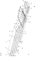
- Fig. 1 shows a telescopic conveyor 1 'from the prior art.
- the telescopic conveyor 1 ' has three belt conveyors 10' which are arranged one above the other and overlapping.
- the length of the telescopic conveyor 1 ' is variable and is adjusted by pulling apart and pushing together the belt conveyors 10' which are movable in the longitudinal direction in relation to one another.
- each belt conveyor 10 ' has a frame which is shown in FIG Fig. 1 is not indexed.
- such frames are formed by profile elements
- the arrangement of the individual frames positioned one above the other is designed, for example as a profile rail with a longitudinal groove, that the frame of a belt conveyor with a counter-profile element, which is also supported by a rail or z.
- T-nuts can be formed, which are attached to a sub-frame, slidably arranged on the sub-frame and slidable on the frame above it / are (not shown).
- Each belt conveyor 10 ' has a circulating belt 12 which is deflected around a deflection roller 13 at a first end A of the belt conveyor 10' and around a deflection roller 14 'at a second end B.
- the second end B of each belt conveyor 10 ' is referred to as the transfer end, at which there is a conventional bridging device 2' which only partially bridges the height difference H to be overcome between two belt conveyors 10 'arranged one above the other.
- the bridging device 2 ' is formed here by a bent end section of the circulating belt 12, which is achieved by a lowered arrangement and a reduced diameter of the deflecting roller 14' at the transfer end B. As in Fig.
- Figures 2 to 10 show telescopic conveyor 1 according to the invention or details thereof. It is noted that the number of belt conveyors 10 of the telescopic conveyor 1 according to the invention is not limited to the number of belt conveyors 10 shown by way of example with the figures. It is readily apparent that a telescopic conveyor 1 according to the invention, starting from two telescopic belt conveyors 10 arranged one above the other, can have any number of telescopic belt conveyors 10 arranged one above the other, in each of which a bridging device 2 according to the invention is arranged between adjacent belt conveyors 10.
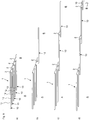
- FIGs 2 to 4b show a telescopic conveyor 1 according to the invention, Fig. 5 and 9 Details of it.
- the telescopic conveyor 1 shows five belt conveyors 10, which are arranged overlapping one above the other and can be moved relative to one another in the longitudinal direction.
- the two lower belt conveyors 10 are shown partially extended, which is only one possible usage arrangement.
- Each belt conveyor 10 has a frame 11, which per se can be designed as in the prior art (and can be mounted on a table, also not shown) and a circulating belt 12 which is deflected at end deflection rollers 13, 14.
- the letter “A” shows the side of the first ends of each belt conveyor 10 with the first deflection roller 13
- the letter “B” illustrates the side of the second ends or transfer ends of each belt conveyor 10 with the second deflection roller 14 , 14 are mounted in roller holders 15.
- Fig 4b shows an example of the conveying mechanism from a lower belt conveyor 10 to an overlying belt conveyor 10: Goods (not shown) are conveyed on the circulating belt 12 of the lower belt conveyor 10 and move on a level E1. Along the ramp 3, the goods pass an incline S and are transferred to the following circulating belt 12 of the belt conveyor 10 above: They now continue to run on the next level E2. Both levels E1, E2 are usually arranged parallel to the floor.
- the belt conveyor 10, which lies in plane E1 is deflected downwards via the deflection roller 4 after passing the ramp 3 and passes under the hold-down roller 5 to continue on level E1. This is the case for all circulating belts 12 which are guided over a bridging device 2.
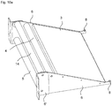
- FIG. 10a This (including a deflection roller 14 which interacts with the bridging device 2) is also shown individually in detail in one embodiment Figure 10a shown. It enables a joint-free transition between two adjacent, stacked belt conveyors 10 of a telescopic conveyor 1.
- one of the bridging devices 2 according to the invention is, see for example.
- Fig. 2 and 3 arranged between two adjacent belt conveyors 10 arranged one above the other. It bridges the height difference H (in Fig. 3 shown) between the two superposed belt conveyors 10 completely and with a steady rise or fall, without forming an abutting edge. As Fig. 3 shows, the remaining gap that still exists between the two belt conveyors between which a transfer takes place is minimized.
- the bridging device 2 also improves the transport from an upper to a lower belt conveyor 10 Avoided abutting edge, so that the articles are conveyed in a more controlled manner when transitioning from an upper to a lower belt conveyor and do not jump or roll away.
- each belt conveyor 10 has a drive roller 17 in the middle area.
- the deflection rollers required for this are omitted here, but are evident from the illustrated guidance of the circulating belt 12 around the drive roller 17, since every change in direction of the belt 12 requires a corresponding deflection means.
- the bridging device 2 has a ramp 3, 3 'which, as in FIG Figures 2 to 5 , 9 and 10 , by an ascending plate 3 or, as in Figures 6 and 7 , can be formed by a plurality of transverse rollers 3 'arranged in a continuously increasing manner.
- the plate 3, which forms the inclined plane of the ramp can also be composed of several parts, which can optionally also be arranged at a distance from one another, as long as they lie in a common plane.
- the alternative embodiment of the ramp 3 ' is not limited to the number of three shown by a plurality of ascending transverse rollers 3'.
- more or fewer transverse rollers 3 ' can be used to form the inclined plane of the ramp, also depending on the height difference H to be overcome.
- a first deflection roller 4 is arranged at the upper end of the ramp 3, 3 'so that a tangential plane of this deflection roller 4 is aligned with the inclined plane provided by the ramp 3, 3'.
- a second deflecting roller 14 is also provided, which is adjacent to the first deflecting roller 4 on the side facing away from the ramp 3, 3 ', but is arranged slightly above it, so that this second deflecting roller 14 also has a tangential plane that coincides with that of the ramp 3 , 3 'provided inclined plane aligns.
- a hold-down roller 5 is arranged below the two deflecting rollers 4, 14, so that the circulating belt 12 of the lower belt conveyor 10 is guided over the ramp 3, 3 ', deflected around the first deflecting roller 4 and passed under the holding-down roller 5, while the circulating belt 12 of the belt conveyor 10 arranged adjacent above it is deflected around the second deflection roller 14 of the bridging device 2, which thus forms the deflection roller 14 at the transfer end of the respective upper belt conveyor 10.
- the bridging device 2 is connected to the second deflection roller 14 with the respective upper belt conveyor 10, while it is longitudinally movable in relation to the frame 11 of the respective lower belt conveyor 10, so that it remains at the respective transfer end B of the respective upper belt conveyor 10 when the belt conveyor 10 is telescoped .
- This is shown in the sequence a) to d) in FIG Fig. 8 shown, in which only the circulating belt 12 is shown for the sake of clarity.
- the area of the transfer device 2 is indicated by dashed lines.
- the block arrow in Figure 8d there next to the letter "B", should be like in Figures 5 to 7 only indicate that the corresponding end of the conveyor belt A, B is outside the display area.
- the telescoping of the telescopic conveyor 1 can be done manually.
- a handle is provided on the lowermost belt conveyor 10 at the second end B, on which, as in FIG Fig. 8 outlined, first the lowermost belt conveyor 10 can be pulled out. If the lowest belt conveyor 10 is completely extended, if the handle 16 is pulled further, the next upper belt conveyor 10 will be pulled out with a forced coupling, etc. When pushing together, the lowest belt conveyor 10 will be pushed in completely before the next upper belt conveyor 10 is pushed in.
- the telescopic conveyor 1 can also be designed so that when the lowest belt conveyor 10 is extended, the upper belt conveyor 10 is also extended successively, similar to a multiple cable mechanism, before the lowest belt conveyor 10 is completely extended.
- a telescopic conveyor 1 can also be extended and retracted automatically if the telescopic belt conveyor 10 is equipped / connected with corresponding hydraulic, pneumatic, electrical and / or mechanical drive and transmission elements and a corresponding control.
- the lock-up device 2 is, see Figure 10a and 10b , laterally bounded by a frame element 6, between which the ramp 3, 3 ', the deflection rollers 4, 14 and the hold-down roller 5 are attached.
- the frame element 6 is here supplemented by an angle piece 6 ', which is also used for attachment to the frame 11 of the respective upper belt conveyor 10, such as. Am Fig. 4 and 5 you can see.
- the angle piece 6 ' overlaps a part of the frame element 6, which is rounded at the upper end to accommodate the deflection rollers 4, 14 like a tab, as in FIG Fig. 10 can be seen, so that the angle piece 6 ′ holds the second deflection roller 14 together with the frame element 6.
- the hold-down roller 5 is only held by the supplementary angle piece 6 '.
- the two lateral frame elements 6 are pivotably connected to the angle piece 6 'so that the ramp 3 is movable and can compensate for uneven floors - the pulley 14 then forms the axis (axis of rotation DA) around which the ramp 3 is pivoted can be, see block arrows.
- the frame element 6 at the lower end of the ramp 3 has a receptacle 8 for a hold-down device 7 (see e.g. Fig. 5 ), which serves to hold down the circulating belt 12 guided over the ramp 3 at its edge so that the belt 12 rests against the ramp 3.
- the hold-down device 7 preferably does not extend across the circulating belt 12, since it would otherwise also form an abutting edge.
- the hold-down device can optionally also be formed in one piece with the frame element, so that there is no need for a receiving device therefor.
- Fig. 9 shows a detail D of the transition between two adjacent belt conveyors 10, as provided by the bridging device 2 according to the invention with the ramp 3, the deflection rollers 4, 14 and the hold-down roller 5 with the described guidance of the circulating belts 12.
- the bridging devices 2 of adjacent belt conveyors 10 come to lie directly adjacent to one another, the ramps 3 and thus the circulating belts 12 of adjacent belt conveyors 10 being aligned with one another with the constant gradient.
- the frame 11 can be seen, on the end face of which the bridging device 2 is attached to the angle piece 6 ', not shown here.
- the frame 11 here consists of several profiles with profile grooves, for. B. profile groove 18, z. B. for mounting the drive roller 17.
Description
Die Erfindung betrifft einen Teleskopförderer mit zwei oder mehr übereinander angeordneten und in Längsrichtung in Bezug zueinander relativ bewegbaren Bandförderern und mit einer Überbrückungsvorrichtung, die die an dem Übergabeende zu überwindende Höhendifferenz zwischen zwei übereinander angeordneten Bandförderern überbrückt.The invention relates to a telescopic conveyor with two or more belt conveyors arranged one above the other and movable in the longitudinal direction relative to one another and with a bridging device which bridges the height difference to be overcome at the transfer end between two belt conveyors arranged one above the other.
Aus dem Stand der Technik sind Teleskopfördereinrichtungen bekannt, die aus zwei oder mehr Förderbändern, hierin auch gleichbedeutend als Bandförderer bezeichnet, bestehen, die in Längsrichtung in Bezug zueinander verfahrbar sind, um so eine Förderstrecke durch Auseinanderfahren entlang ihrer Länge bis zu einer Maximallänge anpassen zu können und/oder die Fördereinrichtung bei Nichtgebrauch platzsparend zusammenfahren zu können.Telescopic conveyor devices are known from the prior art, which consist of two or more conveyor belts, also referred to synonymously as belt conveyors, which can be moved in the longitudinal direction in relation to one another in order to be able to adjust a conveyor path by moving apart along its length up to a maximum length and / or to be able to move the conveyor together in a space-saving manner when not in use.
Da die teleskopierbaren Förderbänder oder Bandförderer bzw. die Förderbandabschnitte bzw. Bandfördererabschnitte übereinander angeordnet sind, kommen die Enden etagenartig übereinander zu liegen, sodass das Fördergut nur in einer Richtung, nämlich vom oberen Bandförderer auf den unteren, transportiert werden kann, wenn apparativ keine Hilfsvorrichtung vorgesehen ist. Eine Umkehrung der Förderrichtung ist nicht ohne weiteres zu bewerkstelligen, da das Fördergut, insbesondere wenn es sich dabei um kleine Artikel handelt, diese Stufe bzw. Stoßkante nicht überwinden kann.Since the telescopic conveyor belts or belt conveyors or the conveyor belt sections or belt conveyor sections are arranged one above the other, the ends come to lie on top of one another in layers so that the conveyed goods can only be transported in one direction, namely from the upper belt conveyor to the lower one, if no auxiliary device is provided is. A reversal of the conveying direction is not easy to accomplish, since the conveyed goods, especially if they are small articles, cannot overcome this step or abutting edge.
Um diese Problemstellung zu lösen, beschreibt
Alternativ dazu gibt es Teleskopförderer, bei denen ein Abschnitt des Umlaufbands an dem Übergabeende, das die Stoßkante bildet, über dem unteren Förderband liegt, um eine tiefer platzierte Umlenkrolle mit kleinerem Durchmesser umgelenkt wird. Auch mit diesem nach unten abgeknickten Endabschnitt wird die zu überwindende Höhendifferenz zwischen übereinander benachbarten Förderbändern verkleinert.As an alternative to this, there are telescopic conveyors in which a section of the circulating belt at the transfer end, which forms the abutting edge, lies above the lower conveyor belt, is deflected around a lower-positioned deflection roller with a smaller diameter. Even with this one When the end section is bent downwards, the height difference to be overcome between conveyor belts adjacent to one another is reduced.
Wenngleich in beiden Fällen ein Transport von einem unteren Förderband bzw. Bandförderer auf ein oberes Förderband bzw. einen Bandförderer ermöglicht wird, besteht doch weiterhin Verbesserungsbedarf, da auch diese Überbrückungsvorrichtungen noch Stoßkanten haben, die nicht nur für kleines Fördergut, sondern auch für Fördergut mit runder Ausformung oder elastischen Materialeigenschaften Hindernisse darstellen. Während zu kleine Förderartikel auch die mit der Rolle bereitgestellte Teilhöhe bzw. die Höhendifferenz bis zum abgeknickten Endabschnitt nicht überwinden können, kann die Stoßkante bei runden und/oder elastischen Artikeln dazu führen, dass diese Artikel weggeschoben werden oder wegspringen; bei scharfkantigen oder kleinen und flachen Gegenständen kann es sogar zum Verklemmen kommen.Although transport from a lower conveyor belt or belt conveyor to an upper conveyor belt or belt conveyor is made possible in both cases, there is still a need for improvement, since these bridging devices also have abutting edges that are not only suitable for small conveyed goods, but also for conveyed goods with round Formation or elastic material properties represent obstacles. While conveyed articles that are too small cannot overcome the partial height provided with the roller or the height difference up to the bent end section, the abutting edge of round and / or elastic articles can lead to these articles being pushed away or jumping away; Sharp-edged or small and flat objects can even jam.
Ausgehend von diesem Stand der Technik ist es Aufgabe der vorliegenden Erfindung, einen Teleskopförderer ohne Stoßkante zwischen direkt übereinander liegenden und folglich benachbarten Bandförderern bereitzustellen, mit dem Fördergut in beide Richtungen störungsfrei transportiert werden kann.Based on this prior art, it is the object of the present invention to provide a telescopic conveyor without an abutting edge between belt conveyors lying directly one above the other and consequently adjacent, with which the conveyed goods can be transported in both directions without interference.
Diese Aufgabe wird durch einen Teleskopförderer mit den Merkmalen des Anspruchs 1 gelöst.This object is achieved by a telescopic conveyor with the features of
Bevorzugte Ausführungsformen sind in den Unteransprüchen ausgeführt.Preferred embodiments are set out in the subclaims.
Ein erfindungsgemäßer Teleskopförderer umfasst gemäß einer ersten Ausführungsform zumindest zwei Bandförderer, die übereinander angeordnet und in Längsrichtung in Bezug zueinander relativ bewegbar sind. Ein solcher Bandförderer umfasst einen Rahmen und ein Umlaufband, das an endständigen Umlenkrollen umgelenkt wird. Eine dieser Umlenkrollen liegt an dem einen Ende ("erstes Ende") jedes Bandförderers vor, das - außer beim obersten Bandförderer - unter dem darüber angeordneten Bandförderer zu liegen kommt, und die zweite Umlenkrolle liegt an dem zweiten Ende vor, das als Übergabeende jedes Bandförderers definiert wird, das - außer beim untersten Bandförderer - auf einem darunter angeordneten Bandförderer endet. Am Übergabeende wird das Fördergut zwischen übereinander liegenden und unmittelbar benachbarten Bandförderern übergeben. Um die Übergabe zu gestalten, ist eine Überbrückungsvorrichtung jeweils zwischen zwei benachbarten Bandförderern vorgesehen. Diese dient dazu, die zu überwindende Höhendifferenz zwischen den beiden unmittelbar übereinander angeordneten Bandförderern zu überbrücken. Gemäß Stand der Technik ist diese Überbrückung bisher nur teilweise bzw. unvollständig möglich.According to a first embodiment, a telescopic conveyor according to the invention comprises at least two belt conveyors which are arranged one above the other and can be moved relative to one another in the longitudinal direction. Such a belt conveyor comprises a frame and a circulating belt, which is deflected on end pulleys. One of these pulleys is at one end ("first end") of each belt conveyor, which - except for the top belt conveyor - comes to lie under the belt conveyor above, and the second pulley is at the second end, which is the transfer end of each belt conveyor is defined, which - except for the lowest belt conveyor - ends on a belt conveyor arranged below. At the end of the transfer, the conveyed goods are transferred between belt conveyors lying one above the other and directly adjacent. To make the handover, a bridging device is between each two adjacent belt conveyors provided. This serves to bridge the height difference to be overcome between the two belt conveyors arranged directly one above the other. According to the state of the art, this bridging has hitherto only been partially or incompletely possible.
Erfindungsgemäß wird die Überbrückung perfektioniert und vervollständigt. Dies bedeutet: der Höhenunterschied bzw. die Lücke zwischen den beiden Bändern, zwischen denen Ware übergeben wird, wird so ideal klein und harmonisch gestaltet, dass die Ware nicht hängen bleibt oder durch eine Stufe an der Übergabestelle einen Impuls erhält, der sie vom Bandförderer springen lässt oder zumindest unerwünscht auf dem Bandförderer versetzt, der die Ware übernimmt.According to the invention, the bridging is perfected and completed. This means: the height difference or the gap between the two belts between which goods are transferred is designed so ideally small and harmonious that the goods do not get stuck or receive an impulse from a step at the transfer point, which makes them jump off the belt conveyor leaves or at least undesirably moved on the belt conveyor that takes over the goods.
Die Überbrückungsvorrichtung ist daher am jeweiligen Übergabeende eines Bandförderers zum Folgebandförderer vorgesehen. Die erfindungsgemäße Überbrückungsvorrichtung weist hierzu eine Rampe mit einer vorbestimmten (durch die zu überwindende Höhe vorgegebene) Steigung und eine erste Umlenkrolle auf, die an dem höher liegenden Ende der Rampe - das also an den darüber liegenden Bandförderer angrenzt - angeordnet ist. Weiter weist die Überbrückungsvorrichtung eine erste Niederhaltevorrichtung an einer Position unterhalb der ersten Umlenkrolle auf, und eine zweite Niederhaltevorrichtung am Fuß der Rampe. Das Umlaufband des jeweils unteren Bandförderers ist damit von einer Förderebene, auf der das Transportgut quasi bodenparallel gefördert wird, unter der zweiten Niederhaltevorrichtung am Fuß der Rampe über diese mit der Steigung geführt und verläuft von dort über die erste Umlenkrolle umgelenkt und unter der ersten Niederhaltevorrichtung hindurch zurück auf die vorgenannte Förderebene dieses Bandförderers. Vorteilhaft setzt sich die Steigung der Rampe stufenlos tangential entlang dem über seine zweite endständige Umlenkrolle geführten unmittelbar nächsthöheren - also über dem Bandförderer mit der eben beschriebenen ersten Förderebene liegenden - Bandförderer fort.The bridging device is therefore provided at the respective transfer end of a belt conveyor to the following belt conveyor. The bridging device according to the invention has for this purpose a ramp with a predetermined slope (predetermined by the height to be overcome) and a first deflection roller which is arranged at the higher end of the ramp - that is, which is adjacent to the belt conveyor above it. Furthermore, the bridging device has a first hold-down device at a position below the first deflection roller, and a second hold-down device at the foot of the ramp. The circulating belt of the respective lower belt conveyor is thus guided from a conveying level on which the transported goods are conveyed virtually parallel to the floor, under the second hold-down device at the foot of the ramp, over this with the gradient and from there it is deflected over the first deflection roller and through under the first hold-down device back to the aforementioned conveyor level of this belt conveyor. Advantageously, the slope of the ramp continues steplessly tangentially along the immediately next higher belt conveyor, which is guided over its second terminal pulley - that is, above the belt conveyor with the first conveying level just described.
Wie der Fachmann weiß, sind Förderanlagen wie der erfindungsgemäße Teleskopförderer oft auch auf sogenannten Tischen - die Tischbeine stehen auf dem Werkhallenboden, der durchaus Unebenheiten im Millimeterbereich haben kann - angebracht. Durch die erfindungsgemäße Überbrückungsvorrichtung und Rampe werden solche Unebenheiten ausgeglichen. Auch beim Fördern auf ein Transportmittel sind Unebenheiten auszugleichen, was durch die erfindungsgemäße Vorrichtung ebenfalls vorteilhaft stufenlos gelingt. So ist am Übergabeende jedes Bandförderers durch die Überbrückungsvorrichtung ein stetiger und damit stufenloser Übergang für zu transportierende Ware sichergestellt - dies wird im Grunde dadurch erreicht, dass eine Tangentialebene der ersten Umlenkrolle, die an dem höher liegenden Ende der Rampe angeordnet ist, und vorzugsweise auch die Tangentialebene der entsprechenden zweiten Umlenkrolle des darüber liegenden Bandförderers, die im Grunde nicht zur Überbrückungsvorrichtung gehört, dieser aber mit zur Wirkung verhilft, mit der durch die Rampe gebildeten schiefen Ebene fluchtet.As a person skilled in the art knows, conveyor systems such as the telescopic conveyor according to the invention are often also attached to so-called tables - the table legs are on the factory floor, which can have unevenness in the millimeter range. Such unevennesses are compensated for by the bridging device and ramp according to the invention. Even when conveying onto a means of transport, unevenness must be compensated for, which is also advantageously achieved continuously with the device according to the invention. At the transfer end of each belt conveyor, the bridging device ensures a steady and thus stepless transition for the goods to be transported - this is basically achieved by the fact that a tangential plane of the first deflection roller, which is arranged at the higher end of the ramp, and preferably also the Tangential plane of the corresponding second deflection roller of the belt conveyor located above, which basically does not belong to the bridging device, but which helps to make it work, is in alignment with the inclined plane formed by the ramp.
Fuß der Rampe meint hierin den Übergang eines jeden Bandes aus seiner bodengleichen Förderebene in die Steigung der Rampe. Damit dort das Band nicht abhebt, muss es niedergehalten werden; ebenso an der Stelle, an der es am Ende der Steigung zurück in die Förderebene geführt werden kann: daher sind an diesen beiden Positionen Niederhaltevorrichtung vorgesehen.The foot of the ramp means the transition of each belt from its floor level conveying level to the slope of the ramp. So that the tape does not lift there, it must be held down; also at the point at which it can be guided back into the conveying level at the end of the incline: therefore, hold-down devices are provided at these two positions.
Die erste Niederhaltevorrichtung, die unter und geeigneter Weiser vor (also vorteilhaft nicht unter der Rampe) der ersten Umlenkrolle des oben liegenden Endes der Rampe vorliegt, kann vorteilhaft eine Niederhalterolle sein, aber auch ein Niederhaltestift oder ein Niederhaltestab sind denkbar. Die zweite Niederhaltevorrichtung am Fuß der Rampe kann ein Niederhaltestift oder Niederhaltestab oder eine Leiste sein - um die Ware nicht zu stören, können auch beidseits an der Breite des Bandes einander gegenüberliegend zwei Niederhaltestifte, -stäbe oder Leistenabschnitte angebracht sein, deren Länge nur so gering ist, dass das Umlaufband zuverlässig niedergehalten und sicher über die Rampe geführt wird. Ein Paar dieser Elemente bildet dann die Niederhaltevorrichtung.The first hold-down device, which is located under and in a suitable manner in front of (i.e. advantageously not under the ramp) the first deflection roller of the overhead end of the ramp, can advantageously be a hold-down roller, but a hold-down pin or a hold-down rod are also conceivable. The second hold-down device at the foot of the ramp can be a hold-down pin or a hold-down bar or a bar - in order not to disturb the goods, two hold-down pins, bars or bar sections can be attached opposite one another across the width of the belt, the length of which is only so short that the conveyor belt is reliably held down and safely guided over the ramp. A pair of these elements then forms the hold-down device.
Zum Begriff "Bandförderer": Dieser hätte auch "Förderband" heißen können; gemeint ist hierin mit "ein Bandförderer" eine Vorrichtung, die einen Rahmen hat, der mindestens zwei seitliche Rahmenteile hat, etwa Profilelementen wie z. B. Profilschienen und ggfs. auch Nutensteine, die über die beidendigen Umlaufrollen und deren Haltevorrichtungen miteinander verbunden sind. Über die Umlaufrollen wird das Umlaufband geführt; das ist soweit dem Fachmann alles bekannt, auch in Bezug auf den Antrieb der Rollen.Regarding the term "belt conveyor": This could also have been called "conveyor belt"; What is meant herein by "a belt conveyor" is a device which has a frame which has at least two lateral frame parts, for example profile elements such as, for. B. profile rails and, if necessary, also T-nuts, which are connected to each other via the two-ended rotating rollers and their holding devices. The circulating belt is guided over the circulating rollers; everything is known to the person skilled in the art, including with regard to the drive of the rollers.
Auch das Anordnen mehrerer Bandförderer übereinander derart, dass bspw. über einen Griff, der an einem untersten der Bandförderer eines Teleskopförderers vorliegt, beginnend mit diesem, der Teleskopförderer ausgezogen werden kann, sodass die relativ zueinander beweglichen Rahmen jedes Bandförderers schubladenartig herausgezogen werden können und dabei über die Nutensteine/Mitnehmer den nächstoberen Rahmen mitnehmen ("teleskopieren"), ist Stand der Technik. Es ist zu beachten, dass sogenannte Universalbänder beidenends bzw. in beide Richtungen ausgezogen werden können; es ist daher auch möglich, dass an einem zuoberst liegenden Förderer ein Griff zum Ausziehen vorliegt. Das Ausziehen kann auch motorisch statt händisch erfolgen, dann liegt statt des Griffs eine entsprechend angetriebene Auszugsvorrichtung vor. Derart über einen Antrieb ausfahrbare Teleskopförderer werden etwa eingesetzt, um den Bandförderer in ein Transportfahrzeug aus dem oder in das gefördert werden soll, zu fahren.Also arranging several belt conveyors on top of each other in such a way that, for example, the telescopic conveyor can be pulled out using a handle that is present on a lowermost of the belt conveyors of a telescopic conveyor, so that the frames of each belt conveyor, which are movable relative to one another, can be pulled out like a drawer can be and thereby take the next upper frame via the sliding blocks / drivers ("telescope"), is state of the art. It should be noted that so-called universal straps can be pulled out at both ends or in both directions; it is therefore also possible for a conveyor located at the top to have a pull-out handle. Pulling out can also be done by motor instead of manually, then instead of the handle there is a correspondingly driven pull-out device. Such telescopic conveyors, which can be extended via a drive, are used, for example, to move the belt conveyor into a transport vehicle from which or into which it is to be conveyed.
Die zweite endständige Umlenkrolle eines oberen Bandförderers eines Teleskopförderers ("oberes" in Bezug auf einen darunter liegenden benachbarten Bandförderer) ist konstruktiv ohnehin dem oberen Rahmen zugeordnet; an diesem kann dann auch die Überbrückungsvorrichtung eines unteren Bandförderers angeordnet und daran befestigt sein, sodass sie in Bezug auf den Rahmen des jeweils unteren Bandförderers längsbeweglich ist. Beim Herausfahren eines unteren Bandförderers verbleibt die Übergabevorrichtung mit dem darüber geführten Umlaufband des unteren Bandförderers am Übergabeende des benachbart darüber angeordneten Bandförderers.The second end pulley of an upper belt conveyor of a telescopic conveyor ("upper" in relation to an adjacent belt conveyor underneath) is structurally assigned to the upper frame in any case; the bridging device of a lower belt conveyor can then also be arranged on this and fastened to it, so that it is longitudinally movable with respect to the frame of the respective lower belt conveyor. When a lower belt conveyor is moved out, the transfer device with the circulating belt of the lower belt conveyor guided over it remains at the transfer end of the belt conveyor arranged adjacent above it.
Die Befestigung der Überbrückungsvorrichtung des unteren Bandförderers und der zweiten endständigen Umlenkrolle des darüber liegenden benachbarten oberen Bandförderers kann über zwei seitliche Rahmenelemente, bevorzugt sogar über jeweils ein mit jedem seitlichen Rahmenelement verbundenes Winkelelement gebildet werden.The attachment of the bridging device of the lower belt conveyor and the second end pulley of the adjacent upper belt conveyor can be formed by two side frame elements, preferably even by an angle element connected to each side frame element.
Die Steigung und die Länge der Rampe sowie die Positionierung der Umlenkrollen sind an die zu überwindende Höhendifferenz zwischen den übereinander benachbarten Bandförderern angepasst. Durch geeignete Wahl der Steigung kann die Überbrückungsvorrichtung an unterschiedliche vorgesehene Fördergeschwindigkeit optimal angepasst gefertigt werden.The incline and length of the ramp as well as the positioning of the deflection rollers are adapted to the height difference to be overcome between the belt conveyors adjacent to one another. By suitable choice of the slope, the bridging device can be manufactured to be optimally adapted to different intended conveying speeds.
Eine Ausführungsform sieht ferner vor, dass die Steigung der Rampe und Position der Rollen zur Anpassung variiert werden können. Dazu können etwa die Überbrückungsvorrichtung des unteren Bandförderers und die zweite endständigen Umlenkrolle des darüber liegenden benachbarten oberen Bandförderers drehgelenkig miteinander verbunden sein, das Drehgelenk verbindet die zwei seitlichen Rahmenelemente mit den angrenzenden Winkelelementen, so dass die Rampe derart beweglich ist, dass dabei Unebenheiten, vorwiegend im Millimeterbereich, ausgeglichen werden können.One embodiment also provides that the slope of the ramp and the position of the rollers can be varied for adaptation. For this purpose, for example, the bridging device of the lower belt conveyor and the second end pulley of the adjacent upper belt conveyor located above can be swivel-jointly connected to one another, the swivel joint connects the two side frame elements with the adjoining angle elements, so that the ramp is movable in such a way that unevenness, predominantly in the millimeter range can be compensated.
Die durch die Rampe bereitgestellte schiefe Ebene kann durch eine Platte oder mehrere stetig ansteigend angeordnete Querrollen gebildet werden.The inclined plane provided by the ramp can be formed by a plate or a plurality of transverse rollers arranged in a continuously rising manner.
Weitere Ausführungsformen sowie einige der Vorteile, die mit diesen und weiteren Ausführungsformen verbunden sind, werden durch die nachfolgende ausführliche Beschreibung unter Bezug auf die begleitenden Figuren deutlich und besser verständlich. Gegenstände oder Teile derselben, die im Wesentlichen gleich oder ähnlich sind, können mit denselben Bezugszeichen versehen sein. Die Figuren sind lediglich eine schematische Darstellung einer Ausführungsform der Erfindung.Further embodiments and some of the advantages associated with these and further embodiments will be made clearer and better understood from the following detailed description with reference to the accompanying figures. Objects or parts thereof that are essentially the same or similar can be provided with the same reference symbols. The figures are only a schematic representation of an embodiment of the invention.
Dabei zeigen:
- Fig. 1
- eine Seitenansicht eines Teleskopförderers aus dem Stand der Technik,
- Fig. 2
- eine Seitenansicht eines erfindungsgemäßen Teleskopförderers,
- Fig. 3
- eine Schnittansicht durch den erfindungsgemäßen Teleskopförderer aus
Fig. 2 , - Fig. 4
-
Fig. 4a eine perspektivische Ansicht auf den erfindungsgemäßen Teleskopförderer ausFig. 2 undFig. 4b die perspektivische Ansicht ausFig. 4a , mit Ebenen, - Fig. 5
- eine vergrößerte perspektivische Teilansicht des erfindungsgemäßen Teleskopförderers aus
Fig. 4 mit Teileinblicken auf die Führung des Förderbands, - Fig. 6
- eine Schnittansicht durch einen Teil eines erfindungsgemäßen Teleskopförderers nach einer alternativen Ausführungsform,
- Fig. 7
- eine Schnittansicht entsprechend
Fig. 6 in einem teilweise teleskopierten Zustand, - Fig. 8
- schematische Seitenansichten der Umlaufbänder eines erfindungsgemäßen Teleskopförderers in a) zusammengeschobenen Zustand und b-d) zunehmend telekopierten Zustand
- Fig. 9
- eine Detailansicht D aus
Fig. 5 des Übergangsbereichs zwischen benachbarten Bandförderern, - Fig. 10
-
Fig. 10a eine perspektivische Ansicht einer Überbrückungsvorrichtung undFig. 10b die Variante dieser Überbrückung mit drehgelenkiger Anordnung.
- Fig. 1
- a side view of a telescopic conveyor from the prior art,
- Fig. 2
- a side view of a telescopic conveyor according to the invention,
- Fig. 3
- a sectional view through the telescopic conveyor according to the invention
Fig. 2 , - Fig. 4
-
Figure 4a a perspective view of the telescopic conveyor according to the inventionFig. 2 andFigure 4b the perspective view fromFigure 4a , with levels, - Fig. 5
- an enlarged perspective partial view of the telescopic conveyor according to the invention
Fig. 4 with partial insights into the guidance of the conveyor belt, - Fig. 6
- a sectional view through part of a telescopic conveyor according to the invention according to an alternative embodiment,
- Fig. 7
- a sectional view accordingly
Fig. 6 in a partially telescoped state, - Fig. 8
- schematic side views of the circulating belts of a telescopic conveyor according to the invention in a) pushed together state and bd) increasingly telescoped state
- Fig. 9
- a detailed view D from
Fig. 5 the transition area between adjacent belt conveyors, - Fig. 10
-
Figure 10a a perspective view of a bridging device andFigure 10b the variant of this bridging with a swivel arrangement.
Die erfindungsgemäße Vorrichtung bezieht sich auf einen Teleskopförderer, bei dem die Höhendifferenz an dem Übergabeende zwischen zwei unmittelbar übereinander angeordneten und damit benachbarten Bandförderern durch eine Überbrückungsvorrichtung ohne Stoßkante überwunden wird, sodass Förderartikel fast jeglicher Größe, Form und auch aus elastischem Material oder auch kleine und kantige Gegenstände störungsfrei oder jedenfalls sehr störungsarm von einem unteren auf einen oberen Bandförderer oder auch umgekehrt transportiert werden können.The device according to the invention relates to a telescopic conveyor in which the height difference at the transfer end between two directly above one another and thus adjacent belt conveyors can be overcome by a bridging device without an abutting edge, so that conveyed articles of almost any size, shape and also made of elastic material or even small and angular objects can be transported from a lower to an upper belt conveyor or vice versa without interference or at least with very little interference.
Jeder Bandförderer 10' weist ein Umlaufband 12 auf, das um eine Umlenkrolle 13 an einem ersten Ende A des Bandförderers 10' und um eine Umlenkrolle 14' an einem zweiten Ende B umgelenkt wird. Das zweite Ende B jedes Bandförderers 10'wird als Übergabeende bezeichnet, an dem sich eine herkömmliche Überbrückungsvorrichtung 2' befindet, die die zu überwindende Höhendifferenz H zwischen zwei übereinander angeordneten Bandförderern 10' nur teilweise überbrückt. Die Überbrückungsvorrichtung 2' wird hier durch einen abgeknickten Endabschnitt des Umlaufbands 12 gebildet, was durch eine abgesenkte Anordnung und einen verringerten Durchmesser der Umlenkrolle 14' am Übergabeende B erreicht wird. Wie in
Jeder Bandförderer 10 hat einen Rahmen 11, der an sich wie im Stand der Technik gestaltet sein kann, (und kann auf einen Tisch montiert sein, ebenfalls nicht dargestellt) und ein Umlaufband 12, das an endständigen Umlenkrollen 13,14 umgelenkt wird. In den Figuren zeigt der Buchstabe "A" jeweils die Seite der ersten Enden jedes Bandförderers 10 mit der ersten Umlenkrolle 13, und Buchstabe "B" verdeutlicht die Seite der zweiten Enden bzw. Übergabeenden jedes Bandförderers 10 mit der zweiten Umlenkrolle 14. Die Umlenkrollen 13,14 sind in Rollenhalterungen 15 gelagert. Wegen des Umlaufbands 12 sind nicht alle Umlenkrollen13,14 zu sehen; in
Diese (einschließlich einer Umlenkrolle 14, die mit der Überbrückungsvorrichtung 2 zusammenwirkt) ist in einer Ausführungsform auch einzeln im Detail in
In
Die erfindungsgemäße Überbrückungsvorrichtung 2 weist eine Rampe 3,3' auf, die, wie in
Am oberen Ende der Rampe 3,3' ist eine erste Umlenkrolle 4 so angeordnet, dass eine Tangentialebene dieser Umlenkrolle 4 mit der durch die Rampe 3,3' bereitgestellten schiefen Ebene fluchtet. Weiter ist eine zweite Umlenkrolle 14 vorgesehen, die auf der von der Rampe 3,3' abgewandten Seite der ersten Umlenkrolle 4 benachbart, aber etwas oberhalb dazu angeordnet ist, sodass auch diese zweite Umlenkrolle 14 eine Tangentialebene aufweist, die mit der durch die Rampe 3,3' bereitgestellten schiefen Ebene fluchtet.A
Unterhalb der beiden Umlenkrollen 4,14 ist eine Niederhalterrolle 5 angeordnet, sodass das Umlaufband 12 des jeweils unteren Bandförderers 10 über die Rampe 3,3' geführt, um die erste Umlenkrolle 4 umgelenkt und unter der Niederhalterrolle 5 durchgeführt wird, während das Umlaufband 12 des benachbart darüber angeordneten Bandförderers 10 um die zweite Umlenkrolle 14 der Überbrückungsvorrichtung 2 umgelenkt wird, die damit die Umlenkrolle 14 am Übergabeende des jeweils oberen Bandförderers 10 bildet. Mit dem über die Rampe 3,3' und die Umlenkrolle 4 geführten Umlaufband 12 des unteren Bandförderers 10 wird die Höhendifferenz H zum benachbarten, oberen Bandförderer 10, dessen Umlaufband 12 von der zweiten Umlenkrolle 14 der Überbrückungsvorrichtung 2 umgelenkt wird, durch einen stetigen Anstieg bzw. Gefälle ohne Stoßkanten überwunden; siehe auch hierzu
Die Überbrückungsvorrichtung 2 ist mit der zweiten Umlenkrolle 14 mit dem jeweils oberen Bandförderer 10 verbunden, während sie in Bezug auf den Rahmen 11 des jeweils unteren Bandförderers 10 längsbeweglich ist, sodass sie beim Teleskopieren der Bandförderer 10 am jeweiligen Übergabeende B des jeweils oberen Bandförderers 10 verbleibt. Dies ist in der schematisch dargestellten Abfolge a) bis d) in
Das Teleskopieren des Teleskopförderers 1 kann händisch erfolgen. Hierzu ist in dem dargestellten Beispiel an dem untersten Bandförderer 10 am zweiten Ende B ein Griff vorgesehen, an dem, wie in
Ferner ist auszuführen, dass es weitere Ausgestaltungen des erfindungsgemäßen Teleskopförderers gibt, bei denen aber nicht der unterste Tisch bzw. der unterste Bandförderer, sondern durchaus auch ein anderer, mittlerer oder sogar der oberste Bandförderer zuerst ausgezogen wird, etwa über entsprechende Füße. Dies ist dem Fachmann aber bekannt und ändert nichts an der technischen Lehre, die durch die Überbrückungsvorrichtung gebildet wird.Furthermore, it should be stated that there are further embodiments of the telescopic conveyor according to the invention, in which, however, not the lowest table or the lowest belt conveyor, but also another, middle or even the uppermost belt conveyor is pulled out first, for example via corresponding feet. However, this is known to the person skilled in the art and does not change the technical teaching that is formed by the bridging device.
Selbstverständlich kann ein erfindungsgemäßer Teleskopförderer 1 auch automatisiert ein- und ausgefahren werden, wenn die teleskopierbaren Bandförderer 10 mit entsprechenden hydraulischen, pneumatischen, elektrischen und/oder mechanischen Antriebs- und Übersetzungselementen und einer entsprechenden Steuerung ausgestattet/verbunden sind.Of course, a
Die Überbrückungsvorrichtung 2 wird, siehe
Wie außerdem die Ausbildung der Vorrichtung in
Weiter weist das Rahmenelement 6 am unteren Ende der Rampe 3 eine Aufnahme 8 für einen Niederhalter 7 auf (vgl. z. B.
- 11
- TeleskopfördererTelescopic conveyor
- 22
- ÜberbrückungsvorrichtungBridging device
- 3,3'3.3 '
- Rampe aus Platte,Slab ramp,
- 3'3 '
- Rampe aus RollenRamp made of rollers
- 44th
- erste endständige Umlenkrollefirst terminal pulley
- 55
- NiederhalterrolleHold-down roll
- 6, 6'6, 6 '
- Rahmenelement, WinkelstückFrame element, elbow
- 77th
- NiederhalterHold-down
- 88th
- NiederhalteraufnahmeHold-down device
- 1010
- BandfördererBelt conveyor
- 1111
- Rahmenframe
- 1212th
- UmlaufbandCirculating belt
- 1313th
- erste Umlenkrollefirst pulley
- 1414th
- zweite endständige Umlenkrollesecond end pulley
- 1515th
- RollenhalterungRoll holder
- 1616
- GriffHandle
- 1717th
- AntriebsrolleDrive roller
- 1818th
- ProfilnutProfile groove
- A,BAWAY
- erstes Ende, zweites bzw. Übergabeendefirst end, second or handover end
- DD.
- Detaildetail
- DATHERE
- DrehachseAxis of rotation
- E1,E2E1, E2
- EbenenLevels
- H,hH, h
- zu überwindende Höhendifferenz, verbleibende StoßkantenhöheDifference in height to be overcome, remaining edge height
- SS.
- Steigungpitch
- 1'1'
- Teleskopförderer, Stand der TechnikTelescopic conveyor, state of the art
- 2'2 '
- Überbrückungsvorrichtung, Stand der TechnikPrior art bridging device
- 4'4 '
- erste endständige Umlenkrolle, Stand der Technikfirst terminal pulley, state of the art
- 10'10 '
- Bandförderer, Stand der TechnikBelt conveyor, state of the art
- 14'14 '
- endständige Umlenkrolleend pulley
Claims (5)
- Telescopic conveyor (1) with at least two belt conveyors (10) arranged one above the other and movable relative to one another in the longitudinal direction, each belt conveyor (10) having- a frame (11),- a circulating belt (12),- a first terminal deflection pulley (13) at a first end (A) and a- second terminal deflection pulley (14) at a second end (B) of the belt conveyor (10), said second end (B) being a transfer end of the belt conveyor (10),and a bridging device (2', 2) being provided between each two adjacent belt conveyors (10) positioned one above the other and which at least partially bridges the height difference (H) to be overcome between the two belt conveyors (10) arranged one above the other at the transfer end,
the bridging device (2) having- a ramp (3, 3') with a slope (S) and- a first deflection pulley (4) arranged at the higher end of the ramp (3, 3'), characterized in that- the bridging device (2) has a first hold-down device (5) arranged below the first deflection pulley (4), and- has a second hold-down device (7) at the foot of the ramp (3, 3'),the circulating belt (12) of each lower belt conveyor (10) passing from one conveying level (E1) below the second hold-down device (7) over the ramp (3, 3') with the slope (S) and from there being deflected by the first deflection pulley (4) and passing underneath the first hold-down device (5) back to the conveying level (E1),
and the slope (S) of the ramp (3, 3') continuing steplessly and tangentially along the circulating belt (12), passing over its second terminal deflection pulley (14), of the belt conveyor (10) positioned above it. - Telescopic conveyor (1) according to claim 1,
characterized in that- the first hold-down device (5) is a hold-down pulley (5), a hold-down pin or a hold-down rod and/or- the second hold-down device (7) is a hold-down pin or a hold-down rod or a bar. - Telescopic conveyor (1) according to claim 1 or 2,
characterized in that
the bridging device (2) of a lower belt conveyor (10) and the second terminal deflection pulley (14) of the adjacent upper belt conveyor (10) positioned above it are fastened in each case to the frame (11) of said upper belt conveyor (10) and is longitudinally movable relative to the frame (11) of each lower belt conveyor (10). - Telescopic conveyor (1) according to claim 3,
characterized in that
the fastening of the bridging device (2) of the lower belt conveyor (10) and of the second terminal deflection pulley (14) of the adjacent upper belt conveyor (10) positioned above it is formed by two lateral frame elements (6), preferably by an angle element (6') connected to each lateral frame element (6). - Telescopic conveyor (1) according to at least one of claims 1 to 4,
characterized in that
the ramp (3, 3') is formed by a plate (3) or by several transverse pulleys (3') arranged continually rising.
Priority Applications (1)
| Application Number | Priority Date | Filing Date | Title |
|---|---|---|---|
| PL18812055T PL3728083T3 (en) | 2017-12-21 | 2018-10-25 | Teleskpic conveyor |
Applications Claiming Priority (2)
| Application Number | Priority Date | Filing Date | Title |
|---|---|---|---|
| DE102017011880.9A DE102017011880B4 (en) | 2017-12-21 | 2017-12-21 | Telescopic conveyor |
| PCT/EP2018/000489 WO2019120597A1 (en) | 2017-12-21 | 2018-10-25 | Telescopic conveyor |
Publications (2)
| Publication Number | Publication Date |
|---|---|
| EP3728083A1 EP3728083A1 (en) | 2020-10-28 |
| EP3728083B1 true EP3728083B1 (en) | 2021-08-11 |
Family
ID=64572282
Family Applications (1)
| Application Number | Title | Priority Date | Filing Date |
|---|---|---|---|
| EP18812055.4A Active EP3728083B1 (en) | 2017-12-21 | 2018-10-25 | Teleskpic conveyor |
Country Status (9)
| Country | Link |
|---|---|
| US (1) | US10899548B2 (en) |
| EP (1) | EP3728083B1 (en) |
| JP (1) | JP2021508307A (en) |
| CN (1) | CN111566024A (en) |
| CA (1) | CA3087157A1 (en) |
| DE (1) | DE102017011880B4 (en) |
| PL (1) | PL3728083T3 (en) |
| RU (1) | RU2020123926A (en) |
| WO (1) | WO2019120597A1 (en) |
Families Citing this family (5)
| Publication number | Priority date | Publication date | Assignee | Title |
|---|---|---|---|---|
| US11021326B2 (en) * | 2018-02-09 | 2021-06-01 | Cyborgline Sa | Conveying apparatus for long pasta |
| EP4031473A4 (en) * | 2020-11-24 | 2023-09-06 | FMH Conveyors LLC | Raised belt transfer unit |
| US11952221B2 (en) * | 2020-12-15 | 2024-04-09 | Express Scripts Strategic Development, Inc. | Dynamic package sortation device |
| CN113844913A (en) * | 2021-08-27 | 2021-12-28 | 中国人民解放军92228部队 | Wharf material conveying device |
| CN115676312B (en) * | 2022-12-29 | 2023-03-14 | 衡水巴迈隆木业有限公司 | Wood raw material conveyor for manufacturing particle board |
Family Cites Families (23)
| Publication number | Priority date | Publication date | Assignee | Title |
|---|---|---|---|---|
| GB758504A (en) | 1953-11-10 | 1956-10-03 | Mikrovaerk As | A delivery arrangement in plants for moulding chocolate and similar confectionery |
| FR1267843A (en) * | 1960-06-13 | 1961-07-28 | Siebert Lefevre Ets | advanced telescopic handler |
| US3332819A (en) | 1961-12-29 | 1967-07-25 | Sicmpelkamp Eugen | Apparatus for separating conveyed sheets |
| US3664488A (en) * | 1969-11-25 | 1972-05-23 | Vyzk Ustav Pozemnick Staveb | Collapsible belt conveyor |
| US3825107A (en) * | 1971-07-26 | 1974-07-23 | M Mahacek | Extendible conveyor system |
| US3826353A (en) * | 1972-08-04 | 1974-07-30 | C Greasley | Conveyors |
| JPS5416457Y2 (en) * | 1975-05-14 | 1979-06-28 | ||
| CH655286A5 (en) * | 1982-05-03 | 1986-04-15 | Sig Schweiz Industrieges | DEVICE FOR SELECTIVELY REDIRECTING OBJECTS ON ONE OF TWO CONVEYOR BELTS, METHOD FOR THEIR OPERATION AND USE. |
| DE4342534C1 (en) * | 1993-12-14 | 1995-01-26 | Caljan Loading Systems | Telescopic conveying path for conveying and measuring piece goods |
| JPH10120139A (en) * | 1996-10-18 | 1998-05-12 | Atex Co Ltd | Conveyor device capable of changing conveying angle |
| US6481563B1 (en) * | 1999-12-29 | 2002-11-19 | Rapistan Systems Advertising Corp. | Extendable conveyor with additional boom section |
| AU2002239807A1 (en) * | 2000-10-20 | 2002-05-27 | Wavexpress, Inc. | Browser including multimedia tool overlay and method of providing a converged multimedia display including user-enhanced data |
| DE10345998B4 (en) | 2003-10-02 | 2013-07-25 | Telair International Ab | System for loading and unloading a cargo space of an aircraft with general cargo |
| DE102006008583B3 (en) * | 2006-02-24 | 2007-08-09 | Gawronski Industrievertretungen Gmbh | Conveyor for transporting articles, has multiple conveyor belts, which have individual frame and individual belt continuously rotating around end-side drums |
| DE202006015281U1 (en) * | 2006-10-04 | 2007-03-08 | Msk-Verpackungs-Systeme Gmbh | Device for raising layer consisting of number of containers, e.g. for use in glass industry, has transport surface that can be guided under the containers of row A |
| DE102009018163B4 (en) * | 2009-04-22 | 2011-03-24 | Gawronski Gmbh Industrievertretungen | Separate device for a conveyor for transporting objects |
| US8496104B2 (en) * | 2010-12-03 | 2013-07-30 | Siemens Industry, Inc. | Extendible conveyor systems and methods |
| US8978871B1 (en) * | 2013-05-22 | 2015-03-17 | Amazon Technologies, Inc. | Conveyor system |
| US9326543B2 (en) * | 2013-08-27 | 2016-05-03 | McEntire Produce, Inc. | System and process for processing fresh produce |
| ES2596259T3 (en) * | 2013-08-29 | 2017-01-05 | Caljan Rite-Hite Aps | Extendable conveyor |
| DE102015003239A1 (en) * | 2015-03-10 | 2016-09-15 | Beumer Gmbh & Co. Kg | Device for loading or unloading a transport container |
| US9828184B1 (en) * | 2016-12-15 | 2017-11-28 | Next Era Belting, Inc. | Portable multi-sectioned boom concrete conveyor assembly |
| US10435246B2 (en) * | 2017-08-30 | 2019-10-08 | Rite-Hite Holding Corporation | Extendible fences for extendible conveyors |
-
2017
- 2017-12-21 DE DE102017011880.9A patent/DE102017011880B4/en not_active Expired - Fee Related
-
2018
- 2018-10-25 EP EP18812055.4A patent/EP3728083B1/en active Active
- 2018-10-25 JP JP2020554365A patent/JP2021508307A/en active Pending
- 2018-10-25 PL PL18812055T patent/PL3728083T3/en unknown
- 2018-10-25 RU RU2020123926A patent/RU2020123926A/en unknown
- 2018-10-25 WO PCT/EP2018/000489 patent/WO2019120597A1/en active Search and Examination
- 2018-10-25 US US16/955,947 patent/US10899548B2/en active Active
- 2018-10-25 CA CA3087157A patent/CA3087157A1/en active Pending
- 2018-10-25 CN CN201880081572.3A patent/CN111566024A/en active Pending
Also Published As
| Publication number | Publication date |
|---|---|
| WO2019120597A1 (en) | 2019-06-27 |
| CA3087157A1 (en) | 2019-06-27 |
| DE102017011880B4 (en) | 2020-06-04 |
| RU2020123926A (en) | 2022-01-21 |
| EP3728083A1 (en) | 2020-10-28 |
| JP2021508307A (en) | 2021-03-04 |
| US20200331702A1 (en) | 2020-10-22 |
| PL3728083T3 (en) | 2022-01-17 |
| DE102017011880A1 (en) | 2019-06-27 |
| US10899548B2 (en) | 2021-01-26 |
| CN111566024A (en) | 2020-08-21 |
Similar Documents
| Publication | Publication Date | Title |
|---|---|---|
| EP3728083B1 (en) | Teleskpic conveyor | |
| EP1275603B1 (en) | Accumulator | |
| EP0541744B1 (en) | Stacking process and device | |
| EP1493692B1 (en) | Releasable tensioning device for an endless conveying belt | |
| EP2826731B1 (en) | Transport robot for goods with retracting handling device | |
| DE202011106265U1 (en) | conveyor | |
| EP1464595B1 (en) | Conveying system for containers, in particular an air port luggage conveying system | |
| EP2878554A1 (en) | Telescopic conveyor belt | |
| EP2314529B1 (en) | Transport unit with accumulation roll chain | |
| DE102014105929B4 (en) | Sliding device for a palletizing device | |
| EP0512446B1 (en) | Arrangement for transforming a multiple track flow of conveyed and close packed containers into several parallel rows of containers, separated from each other by dividing elements | |
| WO2012175161A1 (en) | Transporter | |
| EP2511211B1 (en) | Crossing between two transport routes for transporting flat products lying down | |
| DE102013003587B4 (en) | Outfeed device for use in a conveyor system, discharge module for use in a conveyor system and conveyor system | |
| EP1398141B1 (en) | Folding machine | |
| DE102016113376A1 (en) | transport device | |
| DE102009052336A1 (en) | Loading device for material bars | |
| EP1362817B1 (en) | Device for pushing out printed products stacked on a table | |
| EP0252461A1 (en) | Arrangement for transforming a multi-row stream of bottles into a single-row stream of bottles | |
| DE102010031668A1 (en) | Folding and stacking machine for corrugated board webs | |
| DE19533887C2 (en) | Device for parking several vehicles or the like one above the other | |
| DE3048777A1 (en) | "WORKPIECE CONVEYOR, ESPECIALLY FOR SMALL PARTS" | |
| WO2018015060A1 (en) | Transport device | |
| DE3039075C2 (en) | Soldering machine | |
| WO2018103900A1 (en) | Transport device |
Legal Events
| Date | Code | Title | Description |
|---|---|---|---|
| STAA | Information on the status of an ep patent application or granted ep patent |
Free format text: STATUS: UNKNOWN |
|
| STAA | Information on the status of an ep patent application or granted ep patent |
Free format text: STATUS: THE INTERNATIONAL PUBLICATION HAS BEEN MADE |
|
| PUAI | Public reference made under article 153(3) epc to a published international application that has entered the european phase |
Free format text: ORIGINAL CODE: 0009012 |
|
| STAA | Information on the status of an ep patent application or granted ep patent |
Free format text: STATUS: REQUEST FOR EXAMINATION WAS MADE |
|
| 17P | Request for examination filed |
Effective date: 20200716 |
|
| AK | Designated contracting states |
Kind code of ref document: A1 Designated state(s): AL AT BE BG CH CY CZ DE DK EE ES FI FR GB GR HR HU IE IS IT LI LT LU LV MC MK MT NL NO PL PT RO RS SE SI SK SM TR |
|
| AX | Request for extension of the european patent |
Extension state: BA ME |
|
| DAV | Request for validation of the european patent (deleted) | ||
| DAX | Request for extension of the european patent (deleted) | ||
| GRAP | Despatch of communication of intention to grant a patent |
Free format text: ORIGINAL CODE: EPIDOSNIGR1 |
|
| STAA | Information on the status of an ep patent application or granted ep patent |
Free format text: STATUS: GRANT OF PATENT IS INTENDED |
|
| RIC1 | Information provided on ipc code assigned before grant |
Ipc: B65G 15/26 20060101ALI20210316BHEP Ipc: B65G 15/24 20060101ALI20210316BHEP Ipc: B65G 21/14 20060101AFI20210316BHEP |
|
| INTG | Intention to grant announced |
Effective date: 20210415 |
|
| GRAS | Grant fee paid |
Free format text: ORIGINAL CODE: EPIDOSNIGR3 |
|
| GRAA | (expected) grant |
Free format text: ORIGINAL CODE: 0009210 |
|
| STAA | Information on the status of an ep patent application or granted ep patent |
Free format text: STATUS: THE PATENT HAS BEEN GRANTED |
|
| AK | Designated contracting states |
Kind code of ref document: B1 Designated state(s): AL AT BE BG CH CY CZ DE DK EE ES FI FR GB GR HR HU IE IS IT LI LT LU LV MC MK MT NL NO PL PT RO RS SE SI SK SM TR |
|
| REG | Reference to a national code |
Ref country code: CH Ref legal event code: EP |
|
| REG | Reference to a national code |
Ref country code: DE Ref legal event code: R096 Ref document number: 502018006586 Country of ref document: DE |
|
| REG | Reference to a national code |
Ref country code: IE Ref legal event code: FG4D Free format text: LANGUAGE OF EP DOCUMENT: GERMAN Ref country code: AT Ref legal event code: REF Ref document number: 1419195 Country of ref document: AT Kind code of ref document: T Effective date: 20210915 |
|
| REG | Reference to a national code |
Ref country code: SK Ref legal event code: T3 Ref document number: E 38301 Country of ref document: SK |
|
| REG | Reference to a national code |
Ref country code: LT Ref legal event code: MG9D |
|
| REG | Reference to a national code |
Ref country code: NL Ref legal event code: MP Effective date: 20210811 |
|
| PG25 | Lapsed in a contracting state [announced via postgrant information from national office to epo] |
Ref country code: RS Free format text: LAPSE BECAUSE OF FAILURE TO SUBMIT A TRANSLATION OF THE DESCRIPTION OR TO PAY THE FEE WITHIN THE PRESCRIBED TIME-LIMIT Effective date: 20210811 Ref country code: SE Free format text: LAPSE BECAUSE OF FAILURE TO SUBMIT A TRANSLATION OF THE DESCRIPTION OR TO PAY THE FEE WITHIN THE PRESCRIBED TIME-LIMIT Effective date: 20210811 Ref country code: FI Free format text: LAPSE BECAUSE OF FAILURE TO SUBMIT A TRANSLATION OF THE DESCRIPTION OR TO PAY THE FEE WITHIN THE PRESCRIBED TIME-LIMIT Effective date: 20210811 Ref country code: ES Free format text: LAPSE BECAUSE OF FAILURE TO SUBMIT A TRANSLATION OF THE DESCRIPTION OR TO PAY THE FEE WITHIN THE PRESCRIBED TIME-LIMIT Effective date: 20210811 Ref country code: LT Free format text: LAPSE BECAUSE OF FAILURE TO SUBMIT A TRANSLATION OF THE DESCRIPTION OR TO PAY THE FEE WITHIN THE PRESCRIBED TIME-LIMIT Effective date: 20210811 Ref country code: BG Free format text: LAPSE BECAUSE OF FAILURE TO SUBMIT A TRANSLATION OF THE DESCRIPTION OR TO PAY THE FEE WITHIN THE PRESCRIBED TIME-LIMIT Effective date: 20211111 Ref country code: PT Free format text: LAPSE BECAUSE OF FAILURE TO SUBMIT A TRANSLATION OF THE DESCRIPTION OR TO PAY THE FEE WITHIN THE PRESCRIBED TIME-LIMIT Effective date: 20211213 Ref country code: NO Free format text: LAPSE BECAUSE OF FAILURE TO SUBMIT A TRANSLATION OF THE DESCRIPTION OR TO PAY THE FEE WITHIN THE PRESCRIBED TIME-LIMIT Effective date: 20211111 Ref country code: HR Free format text: LAPSE BECAUSE OF FAILURE TO SUBMIT A TRANSLATION OF THE DESCRIPTION OR TO PAY THE FEE WITHIN THE PRESCRIBED TIME-LIMIT Effective date: 20210811 |
|
| PG25 | Lapsed in a contracting state [announced via postgrant information from national office to epo] |
Ref country code: LV Free format text: LAPSE BECAUSE OF FAILURE TO SUBMIT A TRANSLATION OF THE DESCRIPTION OR TO PAY THE FEE WITHIN THE PRESCRIBED TIME-LIMIT Effective date: 20210811 Ref country code: GR Free format text: LAPSE BECAUSE OF FAILURE TO SUBMIT A TRANSLATION OF THE DESCRIPTION OR TO PAY THE FEE WITHIN THE PRESCRIBED TIME-LIMIT Effective date: 20211112 |
|
| PG25 | Lapsed in a contracting state [announced via postgrant information from national office to epo] |
Ref country code: NL Free format text: LAPSE BECAUSE OF FAILURE TO SUBMIT A TRANSLATION OF THE DESCRIPTION OR TO PAY THE FEE WITHIN THE PRESCRIBED TIME-LIMIT Effective date: 20210811 |
|
| PG25 | Lapsed in a contracting state [announced via postgrant information from national office to epo] |
Ref country code: DK Free format text: LAPSE BECAUSE OF FAILURE TO SUBMIT A TRANSLATION OF THE DESCRIPTION OR TO PAY THE FEE WITHIN THE PRESCRIBED TIME-LIMIT Effective date: 20210811 |
|
| REG | Reference to a national code |
Ref country code: DE Ref legal event code: R097 Ref document number: 502018006586 Country of ref document: DE |
|
| PG25 | Lapsed in a contracting state [announced via postgrant information from national office to epo] |
Ref country code: SM Free format text: LAPSE BECAUSE OF FAILURE TO SUBMIT A TRANSLATION OF THE DESCRIPTION OR TO PAY THE FEE WITHIN THE PRESCRIBED TIME-LIMIT Effective date: 20210811 Ref country code: RO Free format text: LAPSE BECAUSE OF FAILURE TO SUBMIT A TRANSLATION OF THE DESCRIPTION OR TO PAY THE FEE WITHIN THE PRESCRIBED TIME-LIMIT Effective date: 20210811 Ref country code: EE Free format text: LAPSE BECAUSE OF FAILURE TO SUBMIT A TRANSLATION OF THE DESCRIPTION OR TO PAY THE FEE WITHIN THE PRESCRIBED TIME-LIMIT Effective date: 20210811 Ref country code: AL Free format text: LAPSE BECAUSE OF FAILURE TO SUBMIT A TRANSLATION OF THE DESCRIPTION OR TO PAY THE FEE WITHIN THE PRESCRIBED TIME-LIMIT Effective date: 20210811 |
|
| PLBE | No opposition filed within time limit |
Free format text: ORIGINAL CODE: 0009261 |
|
| STAA | Information on the status of an ep patent application or granted ep patent |
Free format text: STATUS: NO OPPOSITION FILED WITHIN TIME LIMIT |
|
| REG | Reference to a national code |
Ref country code: BE Ref legal event code: MM Effective date: 20211031 |
|
| PG25 | Lapsed in a contracting state [announced via postgrant information from national office to epo] |
Ref country code: MC Free format text: LAPSE BECAUSE OF FAILURE TO SUBMIT A TRANSLATION OF THE DESCRIPTION OR TO PAY THE FEE WITHIN THE PRESCRIBED TIME-LIMIT Effective date: 20210811 |
|
| 26N | No opposition filed |
Effective date: 20220512 |
|
| PG25 | Lapsed in a contracting state [announced via postgrant information from national office to epo] |
Ref country code: LU Free format text: LAPSE BECAUSE OF NON-PAYMENT OF DUE FEES Effective date: 20211025 Ref country code: BE Free format text: LAPSE BECAUSE OF NON-PAYMENT OF DUE FEES Effective date: 20211031 |
|
| PG25 | Lapsed in a contracting state [announced via postgrant information from national office to epo] |
Ref country code: IE Free format text: LAPSE BECAUSE OF NON-PAYMENT OF DUE FEES Effective date: 20211025 |
|
| PGFP | Annual fee paid to national office [announced via postgrant information from national office to epo] |
Ref country code: PL Payment date: 20221020 Year of fee payment: 5 |
|
| PG25 | Lapsed in a contracting state [announced via postgrant information from national office to epo] |
Ref country code: CY Free format text: LAPSE BECAUSE OF FAILURE TO SUBMIT A TRANSLATION OF THE DESCRIPTION OR TO PAY THE FEE WITHIN THE PRESCRIBED TIME-LIMIT Effective date: 20210811 |
|
| PG25 | Lapsed in a contracting state [announced via postgrant information from national office to epo] |
Ref country code: HU Free format text: LAPSE BECAUSE OF FAILURE TO SUBMIT A TRANSLATION OF THE DESCRIPTION OR TO PAY THE FEE WITHIN THE PRESCRIBED TIME-LIMIT; INVALID AB INITIO Effective date: 20181025 |
|
| PG25 | Lapsed in a contracting state [announced via postgrant information from national office to epo] |
Ref country code: SI Free format text: LAPSE BECAUSE OF FAILURE TO SUBMIT A TRANSLATION OF THE DESCRIPTION OR TO PAY THE FEE WITHIN THE PRESCRIBED TIME-LIMIT Effective date: 20210811 |
|
| PGFP | Annual fee paid to national office [announced via postgrant information from national office to epo] |
Ref country code: SK Payment date: 20231018 Year of fee payment: 6 |
|
| PGFP | Annual fee paid to national office [announced via postgrant information from national office to epo] |
Ref country code: GB Payment date: 20231025 Year of fee payment: 6 |
|
| PGFP | Annual fee paid to national office [announced via postgrant information from national office to epo] |
Ref country code: IT Payment date: 20231031 Year of fee payment: 6 Ref country code: FR Payment date: 20231023 Year of fee payment: 6 Ref country code: DE Payment date: 20231018 Year of fee payment: 6 Ref country code: CZ Payment date: 20231013 Year of fee payment: 6 Ref country code: CH Payment date: 20231102 Year of fee payment: 6 |
|
| PGFP | Annual fee paid to national office [announced via postgrant information from national office to epo] |
Ref country code: PL Payment date: 20231016 Year of fee payment: 6 |