EP1275603B1 - Accumulator - Google Patents
Accumulator Download PDFInfo
- Publication number
- EP1275603B1 EP1275603B1 EP02405504A EP02405504A EP1275603B1 EP 1275603 B1 EP1275603 B1 EP 1275603B1 EP 02405504 A EP02405504 A EP 02405504A EP 02405504 A EP02405504 A EP 02405504A EP 1275603 B1 EP1275603 B1 EP 1275603B1
- Authority
- EP
- European Patent Office
- Prior art keywords
- strand
- deflecting
- conveying
- storage
- storage apparatus
- Prior art date
- Legal status (The legal status is an assumption and is not a legal conclusion. Google has not performed a legal analysis and makes no representation as to the accuracy of the status listed.)
- Expired - Lifetime
Links
Images


Classifications
-
- B—PERFORMING OPERATIONS; TRANSPORTING
- B65—CONVEYING; PACKING; STORING; HANDLING THIN OR FILAMENTARY MATERIAL
- B65G—TRANSPORT OR STORAGE DEVICES, e.g. CONVEYORS FOR LOADING OR TIPPING, SHOP CONVEYOR SYSTEMS OR PNEUMATIC TUBE CONVEYORS
- B65G47/00—Article or material-handling devices associated with conveyors; Methods employing such devices
- B65G47/34—Devices for discharging articles or materials from conveyor
- B65G47/46—Devices for discharging articles or materials from conveyor and distributing, e.g. automatically, to desired points
- B65G47/51—Devices for discharging articles or materials from conveyor and distributing, e.g. automatically, to desired points according to unprogrammed signals, e.g. influenced by supply situation at destination
- B65G47/5104—Devices for discharging articles or materials from conveyor and distributing, e.g. automatically, to desired points according to unprogrammed signals, e.g. influenced by supply situation at destination for articles
- B65G47/5109—Devices for discharging articles or materials from conveyor and distributing, e.g. automatically, to desired points according to unprogrammed signals, e.g. influenced by supply situation at destination for articles first In - First Out systems: FIFO
- B65G47/5113—Devices for discharging articles or materials from conveyor and distributing, e.g. automatically, to desired points according to unprogrammed signals, e.g. influenced by supply situation at destination for articles first In - First Out systems: FIFO using endless conveyors
- B65G47/5118—Devices for discharging articles or materials from conveyor and distributing, e.g. automatically, to desired points according to unprogrammed signals, e.g. influenced by supply situation at destination for articles first In - First Out systems: FIFO using endless conveyors with variable accumulation capacity
- B65G47/5122—Devices for discharging articles or materials from conveyor and distributing, e.g. automatically, to desired points according to unprogrammed signals, e.g. influenced by supply situation at destination for articles first In - First Out systems: FIFO using endless conveyors with variable accumulation capacity by displacement of the conveyor-guiding means, e.g. of the loose pulley-type
Abstract
Description
Die Erfindung betrifft eine Speichervorrichtung zum Speichern
von entlang einer Förderstrecke von einer Eingangsstation zu einer
Ausgangsstation geförderten Gütern gemäss Oberbegriff des
Patentanspruches 1.The invention relates to a storage device for storing
from along a conveyor line from an input station to a
Starting station promoted goods according to the generic term of
Eine gattungsgemässe Speichervorrichtung ist aus US-A-4'413'724 bzw. aus DE-A 3 225 714 bekannt. Ein Förderband ist schlaufenförmig um mehrere in einer Förderebene angeordnete Umlenkrollen geführt. Einige der Umlenkrollen sind paarweise auf Schlitten angeordnet, welche in der Förderebene verschiebbar sind. Dadurch lassen sich Speicher- und Leertrums bilden, wobei deren Länge und somit die Kapazität des Speichers durch Verschieben der Schlitten veränderbar ist. Diese Speichervorrichtung benötigt relativ viel Platz.A generic memory device is known from US-A-4'413'724 and DE-A 3 225 714, respectively known. A conveyor belt is looped around several in one Conveying plane arranged deflection rollers out. Some of the pulleys are arranged in pairs on sleds, which in the Conveyor plane are displaced. This can be memory and Empty runs form, whereby their length and thus the capacity of the Memory can be changed by moving the carriage. These Storage device requires a lot of space.
DE-A-42'24'609 beschreibt eine Fördervorrichtung für Zigarren, bei welcher ein Förderband in zwei konzentrischen, mit gleicher Steigung um eine gemeinsame vertikale Achse herum angeordnete Wendel gefördert ist. Zum Verändern der Länge der Förderstrecke ist ein die beiden Wendel verbindendes und somit die Förderstrecke überbrückendes Brückenelement vorhanden, welches relativ zu den beiden Wendeln verfahrbar ist. Die wendelförmige Anordnung spart zwar Platz. Nachteilig ist jedoch der benötigte Bandübergang, welcher stets das Risiko birgt, dass Lage und gegenseitiger Abstand der transportierten Güter verändert wird.DE-A-42'24'609 describes a conveyor for cigars, in which a conveyor belt in two concentric, with the same Gradient arranged around a common vertical axis Wendel is promoted. To change the length of the conveyor line is a connecting the two helix and thus the conveyor line bridging bridge element present, which relative to the two spirals is movable. The helical arrangement saves space. However, a disadvantage is the required band transition, which always carries the risk that situation and mutual Distance of transported goods is changed.
Weitere Speichervorrichtungen, welche jedoch alle auch Bandübergänge aufweisen, sind beispielsweise aus DE-A-198'56'649, US-A-6'152'291, US-A-4'549'647 und CH-A-690'646 bekannt. Ergänzend wird noch auf die Speichervorrichtung FR-A-2 810 653 hingewiesen. Sie ist platzsparend, benötigt aber zwei Schlitten für die Umlenkrollen.Other memory devices, which, however, all also band transitions are, for example, DE-A-198'56'649, US-A-6'152'291, US-A-4'549'647 and CH-A-690'646. In addition will Still referring to the memory device FR-A-2 810 653. she is saves space, but requires two carriages for the pulleys.
Es ist deshalb Aufgabe der Erfindung, eine verbesserte Speichervorrichtung der eingangs genannten Art zu schaffen, welche platzsparend ist und trotzdem keine Bandübergänge benötigt.It is therefore an object of the invention to provide an improved storage device to create the type mentioned, which saves space and still needs no tape transitions.
Diese Aufgabe löst eine Speichervorrichtung mit den Merkmalen
des Patentanspruches 1.This object is achieved by a memory device with the features
of
Die erfindungsgemässe Speichervorrichtung weist einen entlang einer Förderebene verschiebbaren Schlitten mit Umlenkungsrollen zur Unterteilung eines endlosen Fördermittels in ein Speichertrum und ein Leertrum auf. Erfindungsgemäss sind erste Umlenkungsmittel vorhanden, welche das Leertrum aus der Förderebene in eine beabstandet dazu parallel verlaufende Ebene umlenken, und zweite Umlenkungsmittel, um das umgelenkte Leertrum wiederum in diese oder eine andere Förderebene in ein Speichertrum überzuführen.The storage device according to the invention has one along a conveying plane slidable carriage with deflection rollers for subdividing an endless conveyor into a storage drum and a leertrum on. According to the invention, first deflection means existing, which the return strand from the conveying plane divert into a spaced parallel plane, and second deflection means to turn the deflected return strand in this or another funding level to transfer into a Speicherertrum.
Da das Leertrum somit auf der Förderebene und quasi auf deren Rückseite verläuft, wird bei maximaler Speicherkapazität in der Förderebene kein zusätzlicher Platz für das Leertrum benötigt. Ferner ermöglicht diese Anordnung eine hohe Flexibilität in der geometrischen Gestaltung der Speichervorrichtung. Insbesondere lässt sich die Speichervorrichtung in einer Ebene oder schraubenförmig anordnen. Vorteilhaft ist ferner, dass auch bei einer schraubenförmigen Anordnung keine Bandübergänge notwendig sind.Since the empty strand thus on the conveyor level and quasi on their Back side runs at maximum storage capacity in the Conveying level no additional space for the empty section needed. Furthermore, this arrangement allows a high flexibility in the geometric design of the storage device. Especially allows the storage device in a plane or helical Arrange. It is also advantageous that even in a helical arrangement no band transitions are necessary.
In einer bevorzugten Ausführungsform ist das Fördermittel eine endlose Plattenkette. Diese weist den Vorteil auf, dass sich auf ihr Kavitäten zur Aufnahme von zu transportierenden Stückgütern anordnen lassen. Zudem ermöglicht sie eine einfache Führung.In a preferred embodiment, the conveying means is a endless plate chain. This has the advantage of being on their cavities for receiving piece goods to be transported arrange to be ordered. It also allows easy guidance.
In einer weiteren bevorzugten Ausführungsform ist das Fördermittel, vorzugsweise eine Plattenkette, im Bereich der Umlenkungsrollen nur einseitig geführt, um die Umlenkung zu vereinfachen, so dass mit grösseren Geschwindigkeiten gefahren werden kann.In a further preferred embodiment, the conveying means, preferably a plate chain, in the region of the deflection rollers only guided on one side to simplify the diversion, so that you can drive at higher speeds.
Weitere vorteilhafte Ausführungsformen gehen aus den abhängigen Patentansprüchen hervor.Further advantageous embodiments are the dependent Claims.
Im folgenden wird der Erfindungsgegenstand anhand von bevorzugten Ausführungsbeispielen, welche in den beiliegenden Zeichnungen dargestellt sind, erläutert. Es zeigen:
Figur 1- eine Draufsicht auf eine Speichervorrichtung gemäss der Erfindung in einer ersten Speicherposition;
Figur 2- die Speichervorrichtung gemäss
Figur 1 in einer zweiten Speicherposition; Figur 3- eine Draufsicht der erfindungsgemässen Speichervorrichtung in einer zweiten Ausführungsform;
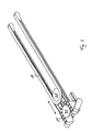
Figur 4- einen Querschnitt durch eine Führung gemäss
Figur 1 entlang A-A; - Figur 5
- einen Querschnitt durch die Führung gemäss
Figur 1 entlang B-B; - Figur 6
- einen Querschnitt durch eine Führung eines Fördermittels in einer zweiten Ausführungsform und
Figur 7- einen Querschnitt durch eine Führung eines Fördermittels in einer dritten Ausführungsform.
- FIG. 1
- a plan view of a storage device according to the invention in a first storage position;
- FIG. 2
- the storage device according to Figure 1 in a second storage position;
- FIG. 3
- a plan view of the inventive storage device in a second embodiment;
- FIG. 4
- a cross section through a guide according to Figure 1 along AA;
- FIG. 5
- a cross section through the guide according to Figure 1 along BB;
- FIG. 6
- a cross section through a guide of a conveying means in a second embodiment and
- FIG. 7
- a cross section through a guide of a conveyor in a third embodiment.
Die Figuren 1 und 2 zeigen eine erfindungsgemässe Speichervorrichtung
in einer ersten Ausführungsform. Auf einem horizontal
angeordneten Trägerrahmen 3 mit zwei parallel zueinander verlaufenden
Trägerelementen 30 ist ein einziges, endloses und flexibles
Fördermittel 1, beispielsweise ein Förderband oder eine
Plattenkette, angeordnet. Dieses Fördermittel 1 transportiert
Stückgüter G von einer hier nicht dargestellten Eingangsstation
zu einer ebenfalls nicht dargestellten Ausgangsstation. Die Eingangsstation
ist beispielsweise mit einer Produktionsstätte, die
Ausgangsstation mit einer Verpackungseinheit verbunden.FIGS. 1 and 2 show a storage device according to the invention
in a first embodiment. On a horizontal
arranged
Im Trägerrahmen 3 ist ein Schlitten 2 entlang einer Geraden verschiebbar
gelagert. Die Verschiebbarkeit ist in den Figuren 1
und 2 mit einem doppelseitigen Pfeil gekennzeichnet. Auf einer
oberen Seite des Schlitten 2 sind zwei Umlenkrollen 21, 21' angeordnet,
um welche das Fördermittel 1 geführt ist. Dadurch ist
das Fördermittel 1 auf dieser oberen Seite in zwei Schlaufen unterteilt,
welche eine gemeinsame Förderebene bilden. Eine erste
Schlaufe bildet ein Speichertrum, die zweite Schlaufe bildet einen
Teil eines Leertrums. Die Bewegungsrichtung des Fördermittels
1 und somit die Förderrichtung ist mit einfachen Pfeilen
dargestellt. Vorzugsweise sind auf dem Schlitten 2 Mittel zur
Spannung des Fördermittels 1 vorhanden. Beispielsweise lassen
sich die Umlenkrollen 21, 21' gegenseitig gefedert lagern.In the
Wie in Figur 1 erkennbar ist, unterteilt die erste Umlenkrolle
21 das Speichertrum in ein eingangsseitiges Speichertrum 10 und
ein ausgangsseitiges Speichertrum 10'. Die zweite Umlenkrolle
21' unterteilt das Leertrum in ein eingangsseitiges oberes
Leertrum 11 und ein ausgangsseitiges oberes Leertrum 11'. Dadurch
sind das Speichertrum und das Leertrum in der Förderebene
in zwei parallel zueinander verlaufende und gegenläufig betriebene
Abschnitte unterteilt.As can be seen in FIG. 1, the first deflection roller is subdivided
21 the storage strand into an input-
Je ein erstes Umlenkungsmittel 31 lenkt je ein oberes Leertrum
11, 11' um den Trägerrahmen 3 herum in eine parallel und
beabstandet zur Förderebene verlaufende Ebene um, wo sie als
umgelenkte, untere Leertrum 12, 12' entlang der gesamten
Unterseite des Trägerrahmens 3 laufen. In einer anderen, hier
nicht dargestellten Ausführungsform ist der Trägerrahmen in
einem Winkel zur Horizontalen oder vertikal ausgerichtet, so
dass das Leertrum auf die Rückseite des Trägerrahmens 3
umgelenkt ist. Das umgelenkte Leertrum 12, 12' ist über zweite
Umlenkungsmittel 32 in das Speichertrum 10,10' übergeführt.Depending on a first deflection means 31 each deflects an
Die ersten und/oder zweiten Umlenkungsmittel 31,32 sind motorisch
angetrieben. In dem hier dargestellten Beispiel sind es
die zweiten Umlenkungsmittel 32, wobei die zwei Umlenkungsmittel
32 je mit einem Motor 4 wirkverbunden sind, so dass der eingangsseitige
und der ausgangsseitige Bereich des Fördermittels 1
unabhängig voneinander antreibbar sind. Der Antrieb erfolgt im
allgemeinen über eine den Förderprozess steuernde, mit der Eingangs-
und Ausgangsstation in kommunikativer Verbindung stehende
Steuereinheit. Werden die Bereiche unterschiedlich angetrieben,
so wird der Schlitten 2 entweder zur Eingangs- oder zur Ausgangsstation
gefahren. Dadurch verändert sich die Länge des
Speichertrums 10, 10' und somit die Speicherkapazität der Speichervorrichtung.
In Figur 1 ist der Speicher halb ausgenützt, in
Figur 2 wird er minimal benötigt.The first and / or second deflection means 31, 32 are motorized
driven. In the example shown here it is
the second deflection means 32, wherein the two deflection means
32 are each operatively connected to a
In Figur 3 ist eine zweite Ausführungsform der erfindungsgemässen
Vorrichtung dargestellt. Hier ist der Trägerrahmen 3 schraubenförmig
gewunden, wobei wiederum das schlaufenförmige Speichertrum
10, 10' auf zwei parallel zueinander verlaufenden oberen
Trägerelementen 30 gelagert ist und das untere umgelenkte
Leertrum 12, 12' auf zwei ebenfalls parallel zueinander verlaufenden
unteren Trägerelementen 30' verläuft. Die Anordnung der
Trägerelemente 30,30' ist vorzugsweise derart, dass unterhalb
jedem oberen Trägerelement 30 ein unteres Trägerelement 30' in
gleichbleibendem Abstand angeordnet ist. Der Trägerrahmen 3 kann
auch so ausgebildet sein, dass je ein oberes und ein unteres
Trägerelement 30,30' einstückig ausgebildet sind. Zudem können
die zwei oberen und/oder die zwei unteren Trägerelemente 30, 30'
miteinander verbunden sein, solange für die Verschiebung des
Schlittens 2 genügend Platz bleibt.FIG. 3 shows a second embodiment of the invention
Device shown. Here, the
Vorzugsweise ist das Fördermittel 1 mindestens in der Förderebene,
vorzugsweise jedoch über mindestens annähernd die gesamte
Laufstrecke des Fördermittels 1 mindestens zweifach geführt gelagert.
Im Bereich der Umlenkungsrollen 21, 21' ist das Fördermittel
1 jedoch aus mindestens einer dieser Führungen entlassen,
um eine Loslösung von den Trägerelementen 30 und eine vereinfachte
Umlenkung zu ermöglichen. Preferably, the
Eine bevorzugte Ausführungsform für diese Führung ist in den Figuren
4 und 5 dargestellt. Das Fördermittel 1, hier eine Plattenkette,
ist gemäss Figur 5 beidseitig im Trägerrahmen 3 geführt.
Der Trägerrahmen ist auf seiner dem Schlitten 2 zugewandten
inneren Seite mit einer stufenförmigen Auflage 34 versehen.
Die Auflage 34 erstreckt sich mindestens annähernd über die gesamte
Länge des Trägerrahmens 3, wobei sie durchgehend oder unterbrochen
sein kann. Das eingangsseitige Speichertrum 10 liegt
auf einer ersten Stufe 34' auf. Selbstverständlich liegen auch
das ausgangsseitige Speichertrum 10' und die oberen Leertrums
11, 11' auf der ersten Stufe 34' auf. Vorzugsweise weist die
Auflage 34 eine zweite Stufe 34'' auf, auf welcher der Schlitten
2 mit einer Trägerplatte 20 aufliegt und geführt ist.A preferred embodiment of this guide is shown in the figures
4 and 5 shown. The
Der Trägerrahmen 3 ist auf seiner dem Schlitten 2 abgewandten
Aussenseite mit einer seitlichen Führung 33 versehen. In dem in
den Figuren 4 und 5 dargestellten Ausführungsbeispiel ist der
Trägerrahmen 3 beidseitig mit einem Abdeckblech 35,35' versehen,
wobei ein äusseres Abdeckblech 35' am oberen Ende rechteckförmig
gebogen ist, so dass die Plattenkette an ihrer Plattenunterseite
an einem ersten Schenkel des Abdeckblechs 35' ansteht und auf
einem zweiten Schenkel des Abdeckblechs 35' aufliegt. Auf dem
zweiten Abdeckblech 35 ist die stufenförmige Auflage 34 angeordnet.
Die unteren Enden der zwei Bleche 35,35' sind vorzugsweise
winklig gebogen, so dass sie in seitliche Nuten 13 der Plattenkette
eingreifen und diese somit führen und lagern. Andere Formen
der seitlichen Lagerung des oberen Trums und der Lagerung
und Führung des unteren Trums sind möglich.The
Gelangt eine Platte der Plattenkette 1 zum Schlitten 2, so
greift, wie in der Figur 4 dargestellt ist, eine der Umlenkrollen
20 oder 21 in die innere seitliche Nut 13 der Platte ein und
hebt die Platte und somit das Fördermittel 1 über eine Kante der
stufenförmigen Auflage 34 und entlässt diese Führung.If a plate of the
In Figur 6 ist eine weitere Art der Führung des oberen Trums
dargestellt. Das untere Trum kann gleich oder verschiedenartig,
beispielsweise wie oben beschrieben, geführt und gelagert sein.
Das obere Trum, hier wiederum durch das eingangsseitige Speichertrum
10 vertreten, ist auf einer Auflageplatte 36 gelagert.
Die Auflageplatte 36 weist auf ihrer äusseren Seite eine seitliche
Führung 36' aufweist, in welche ein unterer Schenkel 14 der
Platte eingreift. Auf der inneren Seite ist am Trägerrahmen 3
ebenfalls eine seitliche, abschnittweise absenkbare Führung 37
angeordnet. Vorzugsweise ist diese Führung durch einzelne vertikal
aufstehende, gefederte Zähne gebildet, welche sich mittels
einer am Schlitten 2 angebrachten Nase absenken lassen. Auch
hier greift die Umlenkrolle 21, 21' wiederum in die Nut 13 der
Platte ein, braucht sie aber nicht aus der Förderebene hochzuheben.In Figure 6 is another type of leadership of the upper strand
shown. The bottom strand can be the same or different,
for example, as described above, be guided and stored.
The upper strand, here again by the entrance-
In Figur 7 ist eine weitere Ausführungsform der Führung des oberen
Trums dargestellt. Auch hier ist aussenseitig eine seitliche
Führung 36' vorhanden. Innenseitig ist keine Führung vorhanden.
Eine präzise Führung wird jedoch dadurch erreicht, dass in einem
oberen Schenkel 36'' der Führung 36' ein Federelement 50 angeordnet
ist, welches den unteren Schenkel 14 der Platte auf die
Auflagefläche der Auflageplatte 36 drückt. Vorzugsweise ist der
untere Schenkel 14 über eine Kugel 51 mit dem Federelement 50
wirkverbunden. Im Bereich des Schlittens wird die Federwirkung
mechanisch oder elektronisch deaktiviert, so dass die Platte
wiederum aus der Führung 36'ausfahrbar ist. In Figure 7 is another embodiment of the guide of the upper
Trums shown. Again, there is a lateral on the outside
Guide 36 'available. There is no guide on the inside.
However, precise guidance is achieved by being in one
upper leg 36 '' of the guide 36 'a
Die erfindungsgemässe Vorrichtung ermöglicht dank der rückseitigen Führung des Leertrums eine platzsparende und leistungsfähige Speicherung ohne Bandübergänge.The inventive device allows thanks to the back Leading the empty section a space-saving and powerful Storage without band transitions.
- 11
- Fördermittelfunding
- 1010
- eingangsseitiges Speichertruminput-side memory channel
- 10'10 '
- ausgangsseitiges Speichertrumoutput-side storage run
- 1111
- eingangsseitiges oberes Leertruminput-side upper empty section
- 11'11 '
- ausgangsseitiges oberes Leertrumoutput side upper empty section
- 1212
- eingangsseitiges unteres Leertruminput-side lower empty strand
- 12'12 '
- ausgangsseitiges unteres Leertrumoutput-side lower empty strand
- 1313
- Nutgroove
- 1414
- unterer Schenkellower thigh
- 22
- Schlittencarriage
- 2020
- Trägerplattesupport plate
- 2121
- erste Umlenkrollefirst pulley
- 21'21 '
- zweite Umlenkrollesecond deflection roller
- 2222
- RadlagerungWheel bearing
- 33
- Trägerrahmensupport frame
- 3030
- oberes Trägerelementupper carrier element
- 30'30 '
- unteres Trägerelementlower carrier element
- 3131
- erste Umlenkmittelfirst deflection
- 3232
- zweite Umlenkmittelsecond deflection means
- 3333
- seitliche Führunglateral guidance
- 3434
- stufenförmige Auflagestepped support
- 34'34 '
- erste Stufefirst stage
- 34''34 ''
- zweite Stufesecond step
- 3535
- inneres Abdeckblech inner cover plate
- 35'35 '
- äusseres Abdeckblechouter cover plate
- 3636
- Auflageplatteplaten
- 36'36 '
- Führungguide
- 36''36 ''
- oberer Schenkelupper leg
- 3737
- innere seitliche Führunginner lateral guidance
- 44
- Motorengine
- 5050
- Federelementspring element
- 5151
- Kugellagerball-bearing
- GG
- Stückgutcargo
Claims (10)
- A storage apparatus for storing goods (G) conveyed along a conveying section from an entry station to an exit station,
having a flexible conveying means (1), it being the case that the conveying means (1) consists of a storage strand (10, 10') and an idle strand (11, 11', 12, 12'), wherein the storage strand (10, 10') and at least one part of the idle strand (11, 11') run in at least one common conveying plane, and wherein the storage strand (10, 10') and the least one part of the idle strand (11, 11'), in this at least one common conveying plane, have in each case two portions which run parallel to one another in a conveying direction and are operated in opposite directions, having a carriage (2) which can be displaced in the conveying plane and is intended for changing a storage capacity of the storage apparatus, wherein the carriage (2) has a first deflecting roller (21) for deflecting the storage strand (10, 10'), and a second deflecting roller (21') for deflecting the idle strand (11, 11'), in the at least one conveying plane, and
having first and second deflecting means (31, 32) for deflecting the conveying means (1),
characterized in that
the first deflecting means (31) deflect the idle strand (11, 11') from the at least one conveying plane into a parallel plane spaced apart therefrom, and that
the second deflecting means (32) transfer the deflected idle strand (12, 12') into the storage strand (10, 10'). - The storage apparatus as claimed in claim 1, characterized in that the carriage (2) can be displaced along a straight line.
- The storage apparatus as claimed in claim1, characterized in that the carriage (2) can be displaced along a helical path.
- The storage apparatus as claimed in claim 1, characterized in that the first and/or the second deflecting means (31, 32) are motor-driven.
- The storage apparatus as claimed in claim 4, characterized in that there are provided a first and second deflecting means (31, 32) on the entry side and exit side, the entry-side and the exit-side deflecting means (31, 32) being driven independently of one another.
- The storage apparatus as claimed in claim 1, characterized in that the conveying means (1) is a plate link chain.
- The storage apparatus as claimed in claim 1, characterized in that the conveying means (1) is guided at least two locations in the at at least one conveying plane, the conveying means (1) is released from at least one of theses guides (21, 21') in the region of the deflecting rollers.
- The storage apparatus as claimed in claim 7, characterized in that the conveying means (1) is guided on a stepped support (34), it being possible for the conveying means (1) to be raised above an edge of a step (34') in the region of the deflecting rollers (21, 21').
- The storage apparatus as claimed in claim 7, characterized in that the conveying means (1) is mounted in a guide (36') on one side and, on the other side, is adjacent to a side guide (37) which can be lowered in the region of the deflecting rollers (21, 21').
- The storage apparatus as claimed in claim 1, characterized in that the conveying means (1) is mounted in a guide (36'), it being forced by a spring onto a support surface, and the spring action being eliminated in the region of the deflecting rollers (21, 21').
Applications Claiming Priority (2)
| Application Number | Priority Date | Filing Date | Title |
|---|---|---|---|
| CH11672001 | 2001-06-26 | ||
| CH11672001 | 2001-06-26 |
Publications (2)
| Publication Number | Publication Date |
|---|---|
| EP1275603A1 EP1275603A1 (en) | 2003-01-15 |
| EP1275603B1 true EP1275603B1 (en) | 2004-03-17 |
Family
ID=4561048
Family Applications (1)
| Application Number | Title | Priority Date | Filing Date |
|---|---|---|---|
| EP02405504A Expired - Lifetime EP1275603B1 (en) | 2001-06-26 | 2002-06-19 | Accumulator |
Country Status (5)
| Country | Link |
|---|---|
| US (1) | US6591963B2 (en) |
| EP (1) | EP1275603B1 (en) |
| AT (1) | ATE261895T1 (en) |
| DE (1) | DE50200295D1 (en) |
| ES (1) | ES2217244T3 (en) |
Cited By (7)
| Publication number | Priority date | Publication date | Assignee | Title |
|---|---|---|---|---|
| US7810629B2 (en) | 2004-02-02 | 2010-10-12 | Krones Ag | Device for dynamic storage of objects |
| US7926642B2 (en) | 2004-10-16 | 2011-04-19 | Krones Ag | Device for the buffering of objects |
| US8028815B2 (en) | 2006-07-29 | 2011-10-04 | Krones Ag | Conveying device |
| US8028820B2 (en) | 2006-02-20 | 2011-10-04 | Krones Ag | Device for storing objects |
| US8162129B2 (en) | 2006-03-16 | 2012-04-24 | Krones Ag | Conveyance means |
| US8162127B2 (en) | 2005-08-27 | 2012-04-24 | Krones Ag | Dynamic storage for objects |
| EP2826735A1 (en) | 2013-07-17 | 2015-01-21 | Krones Aktiengesellschaft | Adjustable storage section of a conveyor device and method for the intermediate storage of items |
Families Citing this family (31)
| Publication number | Priority date | Publication date | Assignee | Title |
|---|---|---|---|---|
| US6497321B2 (en) * | 2001-03-09 | 2002-12-24 | Hartness International, Inc. | Apparatus for diverting a stream of articles |
| FR2807413B1 (en) * | 2000-04-07 | 2002-08-02 | Sogem Agro | ENDLESS BELT-TYPE STORAGE DEVICE |
| US6698581B2 (en) * | 2000-08-29 | 2004-03-02 | Hartness International | Article guide for an apparatus for controlling the flow of articles |
| DE50205746D1 (en) * | 2002-06-25 | 2006-04-13 | Rotzinger Ag Kaiseraugst | Chain memory and method for loading the memory |
| GB2399797B (en) * | 2003-03-25 | 2006-04-26 | Flexlink Components Ab | A variable capacity store for elongated articles |
| DE102004053663A1 (en) * | 2004-02-02 | 2005-08-18 | Krones Ag | Conveyor for dynamic storage of empty plastic bottles comprises conveyor chain divided into conveyor section and empty return section, grippers for bottles being uniformly spaced over entire length of conveyor |
| US7032742B2 (en) * | 2004-04-02 | 2006-04-25 | Hartness International, Inc. | Differential drive spiral accumulator apparatus |
| US7028830B2 (en) * | 2004-05-25 | 2006-04-18 | Hartness International, Inc. | Apparatus for diverting a stream of articles |
| DE102004063704B4 (en) * | 2004-12-28 | 2007-06-06 | Sigma Maschinenbau Gmbh | Telescopic belt conveyor |
| ITBO20050335A1 (en) * | 2005-05-10 | 2005-08-09 | Gd Spa | METHOD AND UNIT FOR PRODUCT GROUPING |
| CH706081B1 (en) * | 2005-05-26 | 2013-08-15 | Rotzinger Ag | Cargo storage. |
| ITBO20060120A1 (en) * | 2006-02-17 | 2006-05-19 | Gd Spa | CHAIN CONVEYOR |
| EP2007663A2 (en) * | 2006-04-20 | 2008-12-31 | Arrowhead Conveyor Corporation, Inc. | Dynamic conveyance device |
| DE102008004775A1 (en) * | 2008-01-16 | 2009-07-23 | Krones Ag | Device for transporting objects |
| NL2002078C (en) * | 2008-10-10 | 2010-04-13 | Specialty Conveyor Bv | A multi-track helical conveyor. |
| FR2938244B1 (en) * | 2008-11-10 | 2012-11-16 | Fege Sarl | DEVICE FOR MOVING ON AN ADAPTABLE TRAVELING ENDLESS STRIP |
| DE102008055531A1 (en) | 2008-12-16 | 2010-06-17 | Krones Ag | Storing device i.e. rotating carrousel, for storing e.g. polyethylene terephthalate beverage bottles, has output station cooperating directly with storage spaces of magazine for receiving articles from storage space |
| CN102482038B (en) | 2009-07-06 | 2014-05-07 | 西德尔合作公司 | Apparatus for handling and accumulating articles in a buffer area |
| EP2428471B1 (en) * | 2010-09-08 | 2013-06-05 | Krones AG | Conveying system |
| DE102010053049B3 (en) * | 2010-12-02 | 2012-04-26 | Khs Gmbh | Device for storing objects and apparatus and method for treating objects |
| US9212008B2 (en) | 2010-12-06 | 2015-12-15 | Barry-Wehmiller Container Systems, Inc. | Conveyor accumulator for controlling the flow of articles being conveyed |
| EP2644538B1 (en) * | 2012-03-27 | 2015-02-25 | Specialty Conveyor B.V. | A conveyor |
| NL2013073B1 (en) | 2014-06-26 | 2016-07-11 | Specialty Conveyor Bv | Portal Accumulator. |
| US9688482B2 (en) | 2015-03-17 | 2017-06-27 | Illinois Tool Works Inc. | Apparatus for buffering the flow of articles |
| US9884723B2 (en) | 2015-07-24 | 2018-02-06 | Ashworth Bros., Inc. | Spiral conveyor system |
| NL2015300B1 (en) | 2015-08-13 | 2017-02-28 | Specialty Conveyor Bv | Buffer device. |
| US9896271B1 (en) | 2016-09-29 | 2018-02-20 | Barry-Wehmiller Container Systems, Inc. | Conveyor accumulator for controlling the flow of articles being conveyed |
| CH713483A1 (en) * | 2017-02-23 | 2018-08-31 | Rotzinger Ag | Chain buffer. |
| DE102018205981A1 (en) * | 2018-04-19 | 2019-10-24 | Krones Ag | Format part for diverting containers |
| IT201900001867A1 (en) * | 2019-02-08 | 2020-08-08 | Cavanna Spa | HORIZONTAL BUFFER DEVICE |
| EP3795502B1 (en) | 2019-09-18 | 2024-02-28 | Specialty Conveyor B.V. | A buffer conveyor |
Family Cites Families (11)
| Publication number | Priority date | Publication date | Assignee | Title |
|---|---|---|---|---|
| US4513858A (en) * | 1981-05-18 | 1985-04-30 | Mapatent, N.V. | Horizontal accumulator |
| US4413724A (en) | 1981-05-18 | 1983-11-08 | Mapatent, N.V. | Horizontal accumulator |
| FR2524436B1 (en) | 1982-04-02 | 1985-09-27 | Nantaise Biscuiterie | REGULATING DEVICE FOR TRANSFERRING IDENTICAL SOLID PRODUCTS BETWEEN UPSTREAM AND DOWNSTREAM MACHINES OF DIFFERENT SPEEDS |
| DE3225714C2 (en) | 1982-07-09 | 1984-11-22 | Edwin 7318 Lenningen Palesch | Chain conveyor |
| DE4224609A1 (en) | 1992-07-25 | 1994-01-27 | Hauni Werke Koerber & Co Kg | Cigarette conveyor |
| US5413213A (en) * | 1992-07-25 | 1995-05-09 | Korber Ag | Apparatus for transporting mass flows of articles |
| CH690646A5 (en) | 1995-05-09 | 2000-11-30 | Ferag Ag | An apparatus for conveying objects. |
| GB9711324D0 (en) * | 1997-06-03 | 1997-07-30 | Molins Plc | Reservoir system for Rod-like articles |
| US6152291A (en) | 1998-03-09 | 2000-11-28 | Hartness International | Apparatus for controlling the flow of articles |
| DE19856649C2 (en) | 1998-12-09 | 2002-08-29 | Franz-Josef Meurer | Method and device for storing material to be conveyed |
| FR2810653B1 (en) | 2000-06-23 | 2002-11-29 | Sogem Agro | U-shaped accumulator device for regulating the transfer of products between an upstream device and a downstream device |
-
2002
- 2002-05-23 US US10/154,374 patent/US6591963B2/en not_active Expired - Lifetime
- 2002-06-19 AT AT02405504T patent/ATE261895T1/en not_active IP Right Cessation
- 2002-06-19 DE DE50200295T patent/DE50200295D1/en not_active Expired - Lifetime
- 2002-06-19 ES ES02405504T patent/ES2217244T3/en not_active Expired - Lifetime
- 2002-06-19 EP EP02405504A patent/EP1275603B1/en not_active Expired - Lifetime
Cited By (9)
| Publication number | Priority date | Publication date | Assignee | Title |
|---|---|---|---|---|
| US7810629B2 (en) | 2004-02-02 | 2010-10-12 | Krones Ag | Device for dynamic storage of objects |
| US7926642B2 (en) | 2004-10-16 | 2011-04-19 | Krones Ag | Device for the buffering of objects |
| US8162127B2 (en) | 2005-08-27 | 2012-04-24 | Krones Ag | Dynamic storage for objects |
| US8028820B2 (en) | 2006-02-20 | 2011-10-04 | Krones Ag | Device for storing objects |
| US8162129B2 (en) | 2006-03-16 | 2012-04-24 | Krones Ag | Conveyance means |
| US8028815B2 (en) | 2006-07-29 | 2011-10-04 | Krones Ag | Conveying device |
| EP2826735A1 (en) | 2013-07-17 | 2015-01-21 | Krones Aktiengesellschaft | Adjustable storage section of a conveyor device and method for the intermediate storage of items |
| DE102013107582A1 (en) | 2013-07-17 | 2015-01-22 | Krones Aktiengesellschaft | Storage section of a conveyor and method for temporarily storing articles |
| US9290321B2 (en) | 2013-07-17 | 2016-03-22 | Krones Ag | Storage section of a conveyor device and method for temporarily storing articles |
Also Published As
| Publication number | Publication date |
|---|---|
| ATE261895T1 (en) | 2004-04-15 |
| EP1275603A1 (en) | 2003-01-15 |
| ES2217244T3 (en) | 2004-11-01 |
| US6591963B2 (en) | 2003-07-15 |
| US20020195317A1 (en) | 2002-12-26 |
| DE50200295D1 (en) | 2004-04-22 |
Similar Documents
| Publication | Publication Date | Title |
|---|---|---|
| EP1275603B1 (en) | Accumulator | |
| DE60211146T2 (en) | DEVICE FOR DISCONNECTING A SHOW CURRENT | |
| DE60021735T2 (en) | TRANSFER OF OBJECTS BETWEEN PROMOTED TRANSFERS | |
| EP0802129B1 (en) | Conveyor path for articles, especially for luggage containers | |
| DE102017011880B4 (en) | Telescopic conveyor | |
| EP2578520A1 (en) | Conveying device | |
| DE3029620A1 (en) | Chain conveyor for workpiece carrier - has endless chains to move carriers around reversing wheels in addition to friction operated chains | |
| EP0773074B1 (en) | Horizontal strip-accumulator | |
| EP1412265B1 (en) | Accumulation-capable curved element for a transfer system | |
| DE3439966C2 (en) | Transport device for piece goods or the like | |
| EP0858961B1 (en) | Conveyer path with V-ribbed belt for articles, especially for luggage containers | |
| DE3125885C2 (en) | Deflection device for piece goods | |
| EP1044108B1 (en) | Device for drawing in a web of endless fabric | |
| DE19947806B4 (en) | Chain drawing machine for continuous drawing of drawn material | |
| DE4112741C2 (en) | Transport tooth chain arrangement | |
| CH689670A5 (en) | Transfer conveyor with a lateral dropping of Stueckguetern preventing side guide. | |
| DE4434146A1 (en) | Conveyor for workpieces | |
| DE3124898C2 (en) | Device for transferring and redirecting pallets | |
| EP0252461A1 (en) | Arrangement for transforming a multi-row stream of bottles into a single-row stream of bottles | |
| EP0088042B1 (en) | Reversible accumulating chain conveyor for elongate goods | |
| EP0936161B1 (en) | Device for driving objects along a given path | |
| DE3820269A1 (en) | ASSEMBLY FOR CONVEYING A PRODUCT FLOW OF PAPER PRODUCTS WITH A SINGLE CONVEYOR BELT PAIRING SYSTEM | |
| DE2264865B2 (en) | Link conveyor belt made of several articulated metal plate links | |
| DE3442978A1 (en) | Piece-goods conveyor | |
| DE1777173A1 (en) | Chain cooling bed for pipes or solid material made of round and square profiles with a long cooling section |
Legal Events
| Date | Code | Title | Description |
|---|---|---|---|
| PUAI | Public reference made under article 153(3) epc to a published international application that has entered the european phase |
Free format text: ORIGINAL CODE: 0009012 |
|
| AK | Designated contracting states |
Kind code of ref document: A1 Designated state(s): AT BE CH CY DE DK ES FI FR GB GR IE IT LI LU MC NL PT SE TR |
|
| AX | Request for extension of the european patent |
Free format text: AL;LT;LV;MK;RO;SI |
|
| 17P | Request for examination filed |
Effective date: 20030220 |
|
| GRAP | Despatch of communication of intention to grant a patent |
Free format text: ORIGINAL CODE: EPIDOSNIGR1 |
|
| AKX | Designation fees paid |
Designated state(s): AT BE CH CY DE DK ES FI FR GB GR IE IT LI LU MC NL PT SE TR |
|
| GRAS | Grant fee paid |
Free format text: ORIGINAL CODE: EPIDOSNIGR3 |
|
| GRAA | (expected) grant |
Free format text: ORIGINAL CODE: 0009210 |
|
| AK | Designated contracting states |
Kind code of ref document: B1 Designated state(s): AT BE CH CY DE DK ES FI FR GB GR IE IT LI LU MC NL PT SE TR |
|
| PG25 | Lapsed in a contracting state [announced via postgrant information from national office to epo] |
Ref country code: TR Free format text: LAPSE BECAUSE OF FAILURE TO SUBMIT A TRANSLATION OF THE DESCRIPTION OR TO PAY THE FEE WITHIN THE PRESCRIBED TIME-LIMIT Effective date: 20040317 Ref country code: IE Free format text: LAPSE BECAUSE OF FAILURE TO SUBMIT A TRANSLATION OF THE DESCRIPTION OR TO PAY THE FEE WITHIN THE PRESCRIBED TIME-LIMIT Effective date: 20040317 Ref country code: FI Free format text: LAPSE BECAUSE OF FAILURE TO SUBMIT A TRANSLATION OF THE DESCRIPTION OR TO PAY THE FEE WITHIN THE PRESCRIBED TIME-LIMIT Effective date: 20040317 Ref country code: CY Free format text: LAPSE BECAUSE OF FAILURE TO SUBMIT A TRANSLATION OF THE DESCRIPTION OR TO PAY THE FEE WITHIN THE PRESCRIBED TIME-LIMIT Effective date: 20040317 |
|
| REG | Reference to a national code |
Ref country code: GB Ref legal event code: FG4D Free format text: NOT ENGLISH |
|
| REG | Reference to a national code |
Ref country code: CH Ref legal event code: NV Representative=s name: ISLER & PEDRAZZINI AG Ref country code: CH Ref legal event code: EP |
|
| GBT | Gb: translation of ep patent filed (gb section 77(6)(a)/1977) |
Effective date: 20040317 |
|
| REG | Reference to a national code |
Ref country code: IE Ref legal event code: FG4D Free format text: GERMAN |
|
| REF | Corresponds to: |
Ref document number: 50200295 Country of ref document: DE Date of ref document: 20040422 Kind code of ref document: P |
|
| REG | Reference to a national code |
Ref country code: SE Ref legal event code: TRGR |
|
| PG25 | Lapsed in a contracting state [announced via postgrant information from national office to epo] |
Ref country code: DK Free format text: LAPSE BECAUSE OF FAILURE TO SUBMIT A TRANSLATION OF THE DESCRIPTION OR TO PAY THE FEE WITHIN THE PRESCRIBED TIME-LIMIT Effective date: 20040617 Ref country code: GR Free format text: LAPSE BECAUSE OF FAILURE TO SUBMIT A TRANSLATION OF THE DESCRIPTION OR TO PAY THE FEE WITHIN THE PRESCRIBED TIME-LIMIT Effective date: 20040617 |
|
| PG25 | Lapsed in a contracting state [announced via postgrant information from national office to epo] |
Ref country code: AT Free format text: LAPSE BECAUSE OF NON-PAYMENT OF DUE FEES Effective date: 20040619 Ref country code: LU Free format text: LAPSE BECAUSE OF NON-PAYMENT OF DUE FEES Effective date: 20040619 |
|
| PG25 | Lapsed in a contracting state [announced via postgrant information from national office to epo] |
Ref country code: BE Free format text: LAPSE BECAUSE OF NON-PAYMENT OF DUE FEES Effective date: 20040630 Ref country code: MC Free format text: LAPSE BECAUSE OF NON-PAYMENT OF DUE FEES Effective date: 20040630 |
|
| REG | Reference to a national code |
Ref country code: IE Ref legal event code: FD4D |
|
| REG | Reference to a national code |
Ref country code: ES Ref legal event code: FG2A Ref document number: 2217244 Country of ref document: ES Kind code of ref document: T3 |
|
| ET | Fr: translation filed | ||
| BERE | Be: lapsed |
Owner name: *SIG PACK SYSTEMS A.G. Effective date: 20040630 |
|
| PLBE | No opposition filed within time limit |
Free format text: ORIGINAL CODE: 0009261 |
|
| STAA | Information on the status of an ep patent application or granted ep patent |
Free format text: STATUS: NO OPPOSITION FILED WITHIN TIME LIMIT |
|
| 26N | No opposition filed |
Effective date: 20041220 |
|
| REG | Reference to a national code |
Ref country code: CH Ref legal event code: PCAR Free format text: ISLER & PEDRAZZINI AG;POSTFACH 1772;8027 ZUERICH (CH) |
|
| PG25 | Lapsed in a contracting state [announced via postgrant information from national office to epo] |
Ref country code: PT Free format text: LAPSE BECAUSE OF NON-PAYMENT OF DUE FEES Effective date: 20040817 |
|
| PGFP | Annual fee paid to national office [announced via postgrant information from national office to epo] |
Ref country code: NL Payment date: 20080618 Year of fee payment: 7 Ref country code: SE Payment date: 20080624 Year of fee payment: 7 |
|
| NLV4 | Nl: lapsed or anulled due to non-payment of the annual fee |
Effective date: 20100101 |
|
| PG25 | Lapsed in a contracting state [announced via postgrant information from national office to epo] |
Ref country code: NL Free format text: LAPSE BECAUSE OF NON-PAYMENT OF DUE FEES Effective date: 20100101 |
|
| PG25 | Lapsed in a contracting state [announced via postgrant information from national office to epo] |
Ref country code: SE Free format text: LAPSE BECAUSE OF NON-PAYMENT OF DUE FEES Effective date: 20090620 |
|
| PGFP | Annual fee paid to national office [announced via postgrant information from national office to epo] |
Ref country code: ES Payment date: 20140618 Year of fee payment: 13 |
|
| REG | Reference to a national code |
Ref country code: DE Ref legal event code: R082 Ref document number: 50200295 Country of ref document: DE Representative=s name: HOEGER, STELLRECHT & PARTNER PATENTANWAELTE MB, DE |
|
| PGFP | Annual fee paid to national office [announced via postgrant information from national office to epo] |
Ref country code: CH Payment date: 20150623 Year of fee payment: 14 Ref country code: GB Payment date: 20150623 Year of fee payment: 14 |
|
| REG | Reference to a national code |
Ref country code: FR Ref legal event code: PLFP Year of fee payment: 15 |
|
| REG | Reference to a national code |
Ref country code: ES Ref legal event code: FD2A Effective date: 20160727 |
|
| PG25 | Lapsed in a contracting state [announced via postgrant information from national office to epo] |
Ref country code: ES Free format text: LAPSE BECAUSE OF NON-PAYMENT OF DUE FEES Effective date: 20150620 |
|
| REG | Reference to a national code |
Ref country code: CH Ref legal event code: PL |
|
| GBPC | Gb: european patent ceased through non-payment of renewal fee |
Effective date: 20160619 |
|
| PG25 | Lapsed in a contracting state [announced via postgrant information from national office to epo] |
Ref country code: CH Free format text: LAPSE BECAUSE OF NON-PAYMENT OF DUE FEES Effective date: 20160630 Ref country code: LI Free format text: LAPSE BECAUSE OF NON-PAYMENT OF DUE FEES Effective date: 20160630 |
|
| PG25 | Lapsed in a contracting state [announced via postgrant information from national office to epo] |
Ref country code: GB Free format text: LAPSE BECAUSE OF NON-PAYMENT OF DUE FEES Effective date: 20160619 |
|
| REG | Reference to a national code |
Ref country code: FR Ref legal event code: PLFP Year of fee payment: 16 |
|
| REG | Reference to a national code |
Ref country code: FR Ref legal event code: PLFP Year of fee payment: 17 |
|
| REG | Reference to a national code |
Ref country code: DE Ref legal event code: R082 Ref document number: 50200295 Country of ref document: DE Representative=s name: HOEGER, STELLRECHT & PARTNER PATENTANWAELTE MB, DE Ref country code: DE Ref legal event code: R082 Ref document number: 50200295 Country of ref document: DE Representative=s name: PATENT- UND RECHTSANWALTSKANZLEI DAUB, DE |
|
| REG | Reference to a national code |
Ref country code: DE Ref legal event code: R082 Ref document number: 50200295 Country of ref document: DE Representative=s name: PATENT- UND RECHTSANWALTSKANZLEI DAUB, DE |
|
| REG | Reference to a national code |
Ref country code: DE Ref legal event code: R081 Ref document number: 50200295 Country of ref document: DE Owner name: SYNTEGON PACKAGING SYSTEMS AG, CH Free format text: FORMER OWNER: SIG PACK SYSTEMS AG, BERINGEN, CH Ref country code: DE Ref legal event code: R082 Ref document number: 50200295 Country of ref document: DE Representative=s name: PATENT- UND RECHTSANWALTSKANZLEI DAUB, DE |
|
| PGFP | Annual fee paid to national office [announced via postgrant information from national office to epo] |
Ref country code: DE Payment date: 20210621 Year of fee payment: 20 Ref country code: FR Payment date: 20210621 Year of fee payment: 20 Ref country code: IT Payment date: 20210630 Year of fee payment: 20 |
|
| REG | Reference to a national code |
Ref country code: DE Ref legal event code: R071 Ref document number: 50200295 Country of ref document: DE |