EP0512446B1 - Arrangement for transforming a multiple track flow of conveyed and close packed containers into several parallel rows of containers, separated from each other by dividing elements - Google Patents
Arrangement for transforming a multiple track flow of conveyed and close packed containers into several parallel rows of containers, separated from each other by dividing elements Download PDFInfo
- Publication number
- EP0512446B1 EP0512446B1 EP92107484A EP92107484A EP0512446B1 EP 0512446 B1 EP0512446 B1 EP 0512446B1 EP 92107484 A EP92107484 A EP 92107484A EP 92107484 A EP92107484 A EP 92107484A EP 0512446 B1 EP0512446 B1 EP 0512446B1
- Authority
- EP
- European Patent Office
- Prior art keywords
- arrangement according
- conveyor
- transition section
- containers
- speed
- Prior art date
- Legal status (The legal status is an assumption and is not a legal conclusion. Google has not performed a legal analysis and makes no representation as to the accuracy of the status listed.)
- Expired - Lifetime
Links
Images


Classifications
-
- B—PERFORMING OPERATIONS; TRANSPORTING
- B65—CONVEYING; PACKING; STORING; HANDLING THIN OR FILAMENTARY MATERIAL
- B65G—TRANSPORT OR STORAGE DEVICES, e.g. CONVEYORS FOR LOADING OR TIPPING, SHOP CONVEYOR SYSTEMS OR PNEUMATIC TUBE CONVEYORS
- B65G47/00—Article or material-handling devices associated with conveyors; Methods employing such devices
- B65G47/52—Devices for transferring articles or materials between conveyors i.e. discharging or feeding devices
- B65G47/68—Devices for transferring articles or materials between conveyors i.e. discharging or feeding devices adapted to receive articles arriving in one layer from one conveyor lane and to transfer them in individual layers to more than one conveyor lane or to one broader conveyor lane, or vice versa, e.g. combining the flows of articles conveyed by more than one conveyor
- B65G47/71—Devices for transferring articles or materials between conveyors i.e. discharging or feeding devices adapted to receive articles arriving in one layer from one conveyor lane and to transfer them in individual layers to more than one conveyor lane or to one broader conveyor lane, or vice versa, e.g. combining the flows of articles conveyed by more than one conveyor the articles being discharged or distributed to several distinct separate conveyors or to a broader conveyor lane
- B65G47/715—Devices for transferring articles or materials between conveyors i.e. discharging or feeding devices adapted to receive articles arriving in one layer from one conveyor lane and to transfer them in individual layers to more than one conveyor lane or to one broader conveyor lane, or vice versa, e.g. combining the flows of articles conveyed by more than one conveyor the articles being discharged or distributed to several distinct separate conveyors or to a broader conveyor lane to a broader conveyor lane
-
- B—PERFORMING OPERATIONS; TRANSPORTING
- B65—CONVEYING; PACKING; STORING; HANDLING THIN OR FILAMENTARY MATERIAL
- B65G—TRANSPORT OR STORAGE DEVICES, e.g. CONVEYORS FOR LOADING OR TIPPING, SHOP CONVEYOR SYSTEMS OR PNEUMATIC TUBE CONVEYORS
- B65G47/00—Article or material-handling devices associated with conveyors; Methods employing such devices
- B65G47/52—Devices for transferring articles or materials between conveyors i.e. discharging or feeding devices
- B65G47/68—Devices for transferring articles or materials between conveyors i.e. discharging or feeding devices adapted to receive articles arriving in one layer from one conveyor lane and to transfer them in individual layers to more than one conveyor lane or to one broader conveyor lane, or vice versa, e.g. combining the flows of articles conveyed by more than one conveyor
- B65G47/681—Devices for transferring articles or materials between conveyors i.e. discharging or feeding devices adapted to receive articles arriving in one layer from one conveyor lane and to transfer them in individual layers to more than one conveyor lane or to one broader conveyor lane, or vice versa, e.g. combining the flows of articles conveyed by more than one conveyor from distinct, separate conveyor lanes
Definitions
- the invention relates to an arrangement according to the preamble of claim 1.
- Multi-lane, tightly packed container stream is to be understood in the sense of the invention as a container stream in which the containers in several tracks or rows are either actually packed tightly, that is to say they are present against one another on their circumferential surfaces, or at least from the design thereof Container flow-promoting transport element forth there is the possibility that the containers also touch different rows or tracks on their peripheral surfaces directly.
- the containers then have an interwoven formation or "honeycomb formation”. This is understood to mean a formation or arrangement in which the containers are offset from one another by half the container diameter in adjacent rows or tracks, ie the containers form "short transverse rows” transversely to the conveying direction, which form an angle of approximately 60 with the conveying direction o include.
- “Separate rows of containers” in the sense of the invention are those rows of containers which extend in the conveying direction, in which the containers of each row of containers are each received by an alley and the containers of an alley by dividing elements, which are formed, for example, by guide rails, from the containers of an adjacent alley are separated.
- An arrangement of the type mentioned at the outset is known (DE-A 37 10 528) and is used, in particular, to form the rows of containers required for a container packing machine from a conveyed container stream.
- a a certain disadvantage of the known arrangement is that the maximum performance achieved with this arrangement (number of containers formed per unit of time) is often not sufficient. This performance limit is due in particular to the very high conveying speed or speed of the conveyor belts at the entrance area of the transition section or to the fact that at high conveying speed there is a high impact speed of the containers on the dividing elements provided for the aisle division and this impact speed is reduced a certain performance leads to destruction of the container, but at least leads to disturbances in the container flow.
- the object of the invention is to develop an arrangement of the type described in such a way that shock-free and pressure-free reshaping is possible with increased performance.
- the conveyed container stream is formed step by step, ie, through the alley division already provided on the transition section, a plurality of likewise multitrack, but separate container streams are initially formed from the multi-lane, densely packed container stream.
- the width or the number of rows or tracks of these separate container streams is smaller than the conveying width, ie the number of rows or tracks of the delivered container stream.
- the containers of the separate, multi-lane container flows are then brought together in an exit region of the transition section to form a respective row of containers.
- the conveying speed at the entrance area can be kept significantly lower compared to the prior art with the same performance of the arrangement, so that a improved, shock and pressure-free forming is possible.
- a significantly higher output is also possible compared to the prior art.
- n-1 for n rows of the conveyed container flow
- the number of impact areas in the invention is many times smaller, i.e. it is (n / n ') - 1.
- n is again the number of rows of containers in the conveyed stream of containers and n' the number of possible rows of containers in each separate row of containers in an aisle of the transition section.
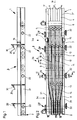
- the embodiment of the arrangement according to the invention shown in the figures essentially has a feed conveyor 1, a discharge conveyor 2 and a transition section 3, which adjoins the feed conveyor in the conveying direction A and is connected upstream of the discharge conveyor 2 in the conveying direction A.
- the feed conveyor 1 consists essentially of a plurality of self-contained and endlessly driven conveyor belts, each of which is formed by hinge belt chains 4 and are arranged with their upper length extending in the conveying direction A directly adjacent to one another transversely to this conveying direction A. With their upper lengths, the hinge band chains 4 thus form an essentially horizontal standing or transport surface for the containers 5, which are upright bottles.
- a driven deflection for the flat top chains 4 and a baffle plate or sliding plate 6 lying approximately at the same level as the transport plane of the feed conveyor 1 and the subsequent transition section 3 are provided.
- the feed conveyor 1 is delimited on each side by a guide railing 7 '.
- Each guide railing 7 ′ extends in the conveying direction A beyond the sliding plate 6 into an input region 3 a of the transition section 3 that adjoins the sliding plate 6.
- the again substantially horizontal standing or transport plane for the containers 5 is formed by the upper lengths of hinge band chains 7 and 8, a hinge band chain 7 connecting to a hinge band chain 8 in the central region 3b of the transition section 3 in the conveying direction A.
- the hinge belt chains 7, which essentially also form the input region 3a of the transition section 3, and the hinge band chains 8, which essentially form the outlet region 3c of the transition section 3 and extend as far as the transition to the conveyor 2, are driven in rotation, namely the hinge belt chains 7 with a somewhat greater speed in comparison to the flat top chains 4 and the flat top chains 8 with a speed which is twice as high as the speed of the flat top chains 7, but also somewhat higher than the speed of the flat top chains of the conveyor 2, ie as the transport speed of the discharge conveyor 2.
- the ratios in which the speeds of the flat top chains 7 and 8 are in relation to one another are predetermined by gear arrangements.
- the hinged belt chains 7 and 8 are driven by a controllable motor, the speed of which is controlled as a function of the power of the downstream container packing machine.
- the speed of the flat top chains 7 is approximately 0.2 m / s and the speed of the flat top chains 8 is approximately 0.4 m / s, the transport speed of the removal conveyor being approximately 0. Is 34 m / s.
- connection areas 9 between the hinge band chains 7 and 8 are each offset in the conveying direction A, in such a way that each continuous area 9 and 8 is adjacent to each connection area 9 transversely to the conveying direction A.
- twelve hinge band chains 7 and 8 are provided next to one another transversely to the conveying direction A and form four groups of three hinge band chains 7 and / or 8 lying next to one another transversely to the conveying direction A
- Formed groups led apart fan-like, mirror-symmetrical to a vertical, including the conveying direction A middle plane M.
- the transition section 3 forms a total of four lanes 10 and 11, of which the outer lanes 10 on the outside by guide rails 12 and inside, ie . H. to the adjacent alley 11 are separated by guide rails 13.
- a guide railing 14 is provided which runs essentially in the central plane M.
- the guide railings 13 and 14 are each designed as double-acting guide railings.
- a jam switch 15 is provided at the transition between the guide railings 7 'and the guide railings 12.
- the guide railings 13 and 14, of which the central guide railing 14 extends much further into the input area 3a are each provided with rollers 16 which are freely rotatable about horizontal axes in order to prevent the containers 5 from colliding to reduce the effect on the front ends of the guide railings 13 and 14 in the conveying direction A and to facilitate the movement of the containers 5 into the alleys 10 and 11, respectively.
- the guide railings 12, 13 and 14 extend essentially parallel to one another in the conveying direction A.
- the guide railings 12 and 13 are guided inwards at an angle to the conveying direction A, so that the alleys 10 and 11, which are initially relatively wide, extend there narrow narrower alleys 10 ′ or 11 ′, which also form the alleys of the discharge conveyor 2 and whose width essentially corresponds to a single-track container flow, ie is essentially the same or slightly larger than the diameter of the container 5.
- the containers 5 are conveyed over the feed conveyor as a tightly packed, multi-lane, i.e. H. in the embodiment shown as an eight-track container flow, in which the containers 5, at least at the end of the feed conveyor 1, not only lie directly against one another with their peripheral surface, but are also offset from one another in a honeycomb fashion such that each container 5 is a row or a track of the multi-track container flow is offset by half the container diameter relative to the containers of an adjacent row of this container flow.
- the baffle plate or sliding plate 6 this interwoven arrangement or honeycomb formation of the containers 5 at the end of the feed conveyor 1 is ensured in any case, since the containers 5 standing on the sliding plate 6 are only conveyed or pushed further by subsequent containers.
- the containers 5 Since the hinged belt chains 7 rotate at a somewhat higher speed than the hinged belt chains 4, the containers 5 form a loosened container flow after passing through the sliding plate 6 at the beginning of the entrance area 3a, but the formation of which can still be influenced by the course, which in the conveying direction has rear edge of the sliding plate 6. Due to the fan-shaped course of the hinge belt chain groups formed by the hinge belt chains 7 at the input area 3a, the container flow is also moved apart transversely to the conveying direction A, i.e.
- short transverse rows each consisting of two containers 5 are formed, in which the two containers 5 in one Axis direction, which is arranged obliquely to the conveying direction A, ie at an angle of approximately 60 ° to the conveying direction A, is arranged next to one another and is spaced apart from one another in the conveying direction A.
- the outer, formed by two containers 5, short and oblique to the conveying direction A transverse rows into the outer lanes 10 and the inner transverse rows into the inner lanes 11 smoothly, so that there is a loosened, initially two-lane container flow in each lane 10 and 11, in which the container 5 the original honeycomb formation are offset from row to row.
- the discharge conveyor 2 via which the containers 5 are fed, for example, to a container packaging machine (not shown), is formed, for example, by four conveyor belts or hinge belt chains and has outer guide rails 12 and inner guide rails 13 and 14 which separate the individual aisles 10 'and 11' from each other form the continuation of the guide railings 12, 13 and 14 of the transition section 3.
- control elements 30 are provided at the beginning of the central region 3b or at the beginning of the alleys 10-11 and at the transition to the exit region 3c, ie where the alleys 10 and 11 narrow. These control elements each have a pivotable arm 31, the length of which is selected and which is arranged above the containers 5 moving past under the respective control element, such that each arm 31 only pivots into a lower position when two successive containers in conveying direction A. 5 have a greater distance from each other. With the control elements 30, the density of the container flow at the entrance or exit of the central region is thus checked at b. On the basis of the signals supplied by these control elements 30, the feed conveyor 1 in particular is controlled in such a way that the desired rows of containers with closely spaced containers 5 result in the alleys 10 'and 11' of the discharge conveyor 2.
- control elements 32 corresponding to the control elements 30 are provided, which monitor the flow of containers in relation to containers 5 that may have fallen over.
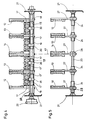
- the top lengths of the hinge band chains 7 and 8 are guided on rail-like or strip-like guide elements 17, each of which has three longitudinal grooves 17 ′ on its top and bottom sides and rest on horizontal cross members 33, which connect the two frame parts 21 to form a frame.
- the three hinge band chains 7 and 8 of a hinge band chain group are guided.
- the flat top chains 7 and 8 are guided on guide elements 17, which, however, are interrupted there at least at the connection regions 9, with both flat top chains 7 and flat top chains 8 being guided in the middle of the central region 3b on the guide elements 17. Since the guide elements 17 are formed symmetrically on their upper and lower sides, the same guide elements 17 can be used at the entrance area 3a for both the hinged belt chains 7, which are separated like a fan to the left.
- the width of the lanes 10 and 11 can be adjusted.
- the guide elements 17 but also the railings 12 and 13 are adjustable perpendicular to the conveying direction A and symmetrically to the central plane M.
- the underside of the guide elements 17 rest on adjusting spindles 18 which extend with their axes in the horizontal direction perpendicular to the conveying direction A and are each provided with a threaded section 19 in the region of each guide element.
- these threaded sections 19 are left-hand threads and on the other side of the center plane M are right-hand threads.
- a nut thread piece 20 is provided on each threaded section 19 and engages in a longitudinal groove 17 'on the underside of the associated guide element 17.
- the nut threads 20 are in the illustrated embodiment provided with a threaded bore plates with a substantially rectangular cross-section.
- the adjusting spindles 18 are rotatably supported at both ends in a frame part 21 of the frame of the arrangement.
- an adjusting wheel 22 with an adjusting scale is provided on one side. This makes it possible to find a setting that has already proven itself for a specific container diameter, even after an adjustment.
- the distance of the individual guide elements 17 and thus the distance of the flat top chains 7 and 8 from the center plane M can be set symmetrically to this center plane, i.e. H. be reduced or enlarged.
- the threaded sections 24 are preferably formed by threaded sleeves, which are pushed onto a shaft forming the adjusting spindle 23 and fastened there in a suitable manner.
- each threaded section 24 there is in turn a nut thread piece 25, which is cuboid in shape and has a groove 25 ′ on two sides offset in the conveying direction A.
- the fork-shaped lower end 26 of a holder 27 of the guide railings 12 and 13 engages in these grooves 25 '.
- the middle guide railing 14 also has the vertical holder 27, which engage with their lower fork-shaped ends 26, however, each in an annular groove in a thickened area 28 of the adjusting spindle 23, so that when the adjusting spindle 23 is rotated, the central position, ie the position in the region of the central plane M, for the central railing 14 is maintained .
- Each adjusting spindle 23 is connected to the associated adjusting spindle 18 via a drive 29, for example via a chain drive, so that both the guide elements 17 and thus the flat top chains 7 and 8 as well as the guide rails 12 and 13 are adjusted by turning an adjusting wheel 22. Due to the above-described attachment of the guide railings 12, 13 and 14 to the adjusting spindles 23 and the nut threads 25 there, it is possible to remove or replace these guide railings 12, 13 and 14 by simply lifting them off.
Abstract
Description
Die Erfindung bezieht sich auf eine Anordnung gemäß Oberbegriff Patentanspruch 1.The invention relates to an arrangement according to the preamble of claim 1.
Unter "mehrspuriger, dicht gepackter Behälterstrom" ist im Sinne der Erfindung ein Behälterstrom zu verstehen, in welchem die Behälter in mehreren Spuren bzw. Reihen entweder tatsächlich dicht gepackt, d. h. an ihren Umfangsflächen gegeneinander anliegend vorhanden sind, oder aber zumindest von der Ausbildung des diesen Behälterstrom fördernden Transportelementes her die Möglichkeit besteht, daß sich die Behälter auch unterschiedlicher Reihen bzw. Spuren an ihren Umfangsflächen unmittelbar berühren. In einem solchen, mehrspurigen und dicht gepackten Behälterstrom weisen die Behälter dann eine verwabte Formation bzw. "Waben-Formation" auf. Hierunter ist eine Formation bzw. Anordnung zu verstehen, in der die Behälter in jeweils benachbarten Reihen bzw. Spuren um den halben Behälterdurchmesser gegeneinander versetzt sind, d. h. die Behälter quer zur Förderrichtung "kurze Querreihen" bilden, die mit der Förderrichtung einen Winkel von etwa 60o einschließen."Multi-lane, tightly packed container stream" is to be understood in the sense of the invention as a container stream in which the containers in several tracks or rows are either actually packed tightly, that is to say they are present against one another on their circumferential surfaces, or at least from the design thereof Container flow-promoting transport element forth there is the possibility that the containers also touch different rows or tracks on their peripheral surfaces directly. In such a multi-lane and densely packed container stream, the containers then have an interwoven formation or "honeycomb formation". This is understood to mean a formation or arrangement in which the containers are offset from one another by half the container diameter in adjacent rows or tracks, ie the containers form "short transverse rows" transversely to the conveying direction, which form an angle of approximately 60 with the conveying direction o include.
"Voneinander getrennte Behälterreihen" sind im Sinne der Erfindung solche, sich in Förderrichtung erstreckende Behälterreihen, bei denen die Behälter jeder Behälterreihe jeweils von einer Gasse aufgenommen und die Behälter einer Gasse durch Einteilelemente, die beispielsweise von Führungsgeländern gebildet sind, von den Behältern einer benachbarten Gasse getrennt sind."Separate rows of containers" in the sense of the invention are those rows of containers which extend in the conveying direction, in which the containers of each row of containers are each received by an alley and the containers of an alley by dividing elements, which are formed, for example, by guide rails, from the containers of an adjacent alley are separated.
Eine Anordnung der eingangs erwähnten Art ist bekannt (DE-A 37 10 528) und dient insbes. dazu, um aus einem angeförderten Behälterstrom die für eine Behältereinpackmaschine erforderlichen Behälterreihen zu bilden. Ein gewisser Nachteil der bekannten Anordnung besteht darin, daß die mit dieser Anordnung maximal erreichte Leistung (Anzahl der umgeformten Behälter je Zeiteinheit) vielfach nicht ausreicht. Diese Leistungsgrenze ist insbes. durch die bei hohen Leistungen sehr hohe Fördergeschwindigkeit bzw. Geschwindigkeit der Förderbänder auch am Eingangsbereich der Übergangsstrecke bzw. dadurch bedingt, daß bei hoher Fördergeschwindigkeit sich eine hohe Aufprallgeschwindigkeit der Behälter an den für die Gasseneinteilung vorgesehenen Einteilelementen ergibt und diese Aufprallgeschwindigkeit ab einer bestimmten Leistung zu einem Zerstören der Behälter, zumindest jedoch zu Störungen im Behälterfluß führt.An arrangement of the type mentioned at the outset is known (DE-A 37 10 528) and is used, in particular, to form the rows of containers required for a container packing machine from a conveyed container stream. A a certain disadvantage of the known arrangement is that the maximum performance achieved with this arrangement (number of containers formed per unit of time) is often not sufficient. This performance limit is due in particular to the very high conveying speed or speed of the conveyor belts at the entrance area of the transition section or to the fact that at high conveying speed there is a high impact speed of the containers on the dividing elements provided for the aisle division and this impact speed is reduced a certain performance leads to destruction of the container, but at least leads to disturbances in the container flow.
Aufgabe der Erfindung ist es, eine Anordnung der eingangs geschilderten Art so weiterzubilden, daß mit ihr bei gesteigerter Leistung eine stoß- und druckfreie Umformung möglich ist.The object of the invention is to develop an arrangement of the type described in such a way that shock-free and pressure-free reshaping is possible with increased performance.
Zur Lösung dieser Aufgabe ist eine Anordnung entsprechend dem kennzeichnenden Teil des Patentanspruches 1 ausgebildet.To solve this problem, an arrangement is designed according to the characterizing part of claim 1.
Bei der erfindungsgemäßen Anordnung erfolgt die Umformung des angeförderten Behälterstrom schrittweise, d.h. durch die bereits an der Übergangsstrecke vorgesehene Gasseneinteilung werden aus dem mehrspurigen, dichtgepackten Behälterstrom zunächst mehrere ebenfalls mehrspurige, allerdings voneinander getrennte Behälterströme gebildet. Die Breite bzw. die Anzahl der Reihen bzw. Spuren dieser getrennten Behälterströme ist kleiner als die Förderbreite, d.h. die Anzahl der Reihen oder Spuren des angeförderten Behälterstromes. Die Behälter der getrennten, mehrspurigen Behälterströme werden dann in einem Ausgangsbereich der Übergangsstrecke zu jeweils einer Behälterreihe zusammengeführt. Durch diese stufenweise Umformung, bei der die Anzahl der Behälterreihen des mehrspurigen, angeförderten Behälterstromes größer ist als die Anzahl der voneinander getrennten Behälterreihen am Abförderer kann im Vergleich zum Stand der Technik bei gleicher Leistung der Anordnung die Fördergeschwindigkeit am Eingangsbereich wesentlich geringer gehalten werden, so daß eine verbesserte, stoß- und druckfreie Umformung möglich ist. Bei gleichgroßer Fördergeschwindigkeit am Eingangsbereich der Übergangsstrecke ist aber auch im Vergleich zum Stand der Technik eine wesentlich höhere Leistung möglich.In the arrangement according to the invention, the conveyed container stream is formed step by step, ie, through the alley division already provided on the transition section, a plurality of likewise multitrack, but separate container streams are initially formed from the multi-lane, densely packed container stream. The width or the number of rows or tracks of these separate container streams is smaller than the conveying width, ie the number of rows or tracks of the delivered container stream. The containers of the separate, multi-lane container flows are then brought together in an exit region of the transition section to form a respective row of containers. Due to this gradual reshaping, in which the number of rows of containers of the multi-lane, supplied stream of containers is greater than the number of separate rows of containers on the discharge conveyor, the conveying speed at the entrance area can be kept significantly lower compared to the prior art with the same performance of the arrangement, so that a improved, shock and pressure-free forming is possible. With the same conveying speed at the entrance area of the transition section, however, a significantly higher output is also possible compared to the prior art.
Entscheidend ist bei der erfindungsgemäßen Anordnung auch, daß durch die stufenförmige Umformung die für das Aufprallen der Behälter und für hieraus evtl. resultierende Betriebsstörungen besonders kritischen Aufprallbereiche, nämlich die im Behälterstrom liegenden freien Enden der Einteilelemente in ihrer Anzahl bezogen auf die Anzahl der Behälterreihen des angeförderten Behälterstromes stark reduziert sind.It is also decisive in the arrangement according to the invention that, due to the step-like shaping, the impact areas which are particularly critical for the impact of the containers and for any operational disturbances resulting therefrom, namely the number of free ends of the dividing elements located in the container stream in relation to the number of rows of containers conveyed Container flow are greatly reduced.
Während nämlich beim Stand der Technik bei n Reihen des angeförderten Behälterstroms die Anzahl dieser Aufprallbereiche gleich n-1 ist, ist die Anzahl der Aufprallbereiche bei der Erfindung um ein Vielfaches kleiner, d.h. sie beträgt (n/n') - 1. Hierbei ist n wiederum die Anzahl der Behälterreihen im angeförderten Behälterstrom und n' die Anzahl der möglichen Behälterreihen in jeder getrennten Behälterreihe einer Gasse der Übergangsstrecke.Namely, while in the prior art the number of these impact areas is n-1 for n rows of the conveyed container flow, the number of impact areas in the invention is many times smaller, i.e. it is (n / n ') - 1. Here, n is again the number of rows of containers in the conveyed stream of containers and n' the number of possible rows of containers in each separate row of containers in an aisle of the transition section.
Weiterbildungen der Erfindung sind Gegenstand der Unteransprüche.Developments of the invention are the subject of the dependent claims.
Die Erfindung wird im folgenden anhand der Figuren an einem Ausführungsbeispiel näher erläutert. Es zeigen:
- Fig. 1
- in vereinfachter Darstellung und in Seitenansicht eine Ausführungsform der erfindungsgemäßen Anordnung;
- Fig. 2
- eine Draufsicht auf die Anordnung gemäß Fig. 1, und zwar zusammen mit einigen den angeförderten Behälterstrom sowie die Behälterreihen bildenden Behältern;
- Fig. 3
- eine Darstellung wie Fig. 2, jedoch mit einer Vielzahl von Behältern;
- Fig. 4
- einen Schnitt entsprechend der Linie I-I der Fig. 2;
- Fig. 5
- einen Schnitt entsprechend der Linie II-II der Fig. 2;
- Fig. 6
- in vergrößerter Darstellung ein Verstellelement für ein Führungsgeländer der Anordnung;
- Fig. 7
- einen Schnitt entsprechend der Linie III-III der Fig. 6.
- Fig. 1
- in a simplified representation and in side view an embodiment of the arrangement according to the invention;
- Fig. 2
- a plan view of the arrangement of Figure 1, together with some of the container flow and the container rows forming containers.
- Fig. 3
- a representation like Figure 2, but with a variety of containers.
- Fig. 4
- a section along the line II of Fig. 2;
- Fig. 5
- a section along the line II-II of Fig. 2;
- Fig. 6
- in an enlarged view an adjusting element for a guide railing of the arrangement;
- Fig. 7
- a section along the line III-III of FIG. 6th
Die in den Figuren dargestellte Ausführungsform der erfindungsgemäßen Anordnung weist im wesentlichen einen Zuförderer 1, einen Abförderer 2 sowie eine Übergangsstrecke 3 auf, die sich in Förderrichtung A an den Zuförderer anschließt und dem Abförderer 2 in Förderrichtung A vorgeschaltet ist.The embodiment of the arrangement according to the invention shown in the figures essentially has a feed conveyor 1, a
Der Zuförderer 1 besteht im wesentlichen aus mehreren, in sich geschlossenen und endlos umlaufend angetriebenen Förderbändern, die jeweils von Scharnierbandketten 4 gebildet sind und mit ihren oberen, sich in Förderrichtung A erstreckenden Länge quer zu dieser Förderrichtung A unmittelbar aneinander angrenzend angeordnet sind. Die Scharnierbandketten 4 bilden somit mit ihren oberen Längen eine im wesentlichen horizontale Stand- oder Transportfläche für die Behälter 5, die aufrechtstehende Flaschen sind.The feed conveyor 1 consists essentially of a plurality of self-contained and endlessly driven conveyor belts, each of which is formed by
Am Übergang zwischen dem Zuförderer 1 und der Übergangsstrecke 3 ist eine angetriebene Umlenkung für die Scharnierbandketten 4 sowie ein in etwa niveaugleich mit der Transportebene des Zuförderers 1 und der anschließenden Übergangsstrecke 3 liegendes Stau- oder Gleitblech 6 vorgesehen. Quer zur Förderrichtung A ist der Zuförderer 1 an jeder Seite durch ein Führungsgeländer 7' begrenzt. Jedes Führungsgeländer 7' erstreckt sich in Förderrichtung A über das Gleitblech 6 hinaus in einen sich an das Gleitblech 6 anschließenden Eingangsbereich 3a der Übergangsstrecke 3.At the transition between the feed conveyor 1 and the
An der Übergangsstrecke 3 ist die wiederum im wesentlichen horizontale Stand- bzw. Transportebene für die Behälter 5 von den oberen Längen von Scharnierbandketten 7 und 8 gebildet, wobei jeweils im Mittelbereich 3b der Übergangsstrecke 3 in Förderrichtung A eine Scharnierbandkette 7 an eine Scharnierbandkette 8 anschließt.At the
Die Scharnierbandketten 7, die im wesentlichen auch den Eingangsbereich 3a der Übergangsstrecke 3 bilden, und die Scharnierbandketten 8, die im wesentlichen den Ausgangsbereich 3c der Übergangsstrecke 3 bilden und bis an den Übergang zum Abförderer 2 reichen, sind umlaufend angetrieben, und zwar die Scharnierbandketten 7 mit einer im Vergleich zu den Scharnierbandketten 4 etwas größeren Geschwindigkeit und die Scharnierbandketten 8 mit einer Geschwindigkeit, die um das Doppelte größer ist als die Geschwindigkeit der Scharnierbandketten 7, aber auch etwas größer ist als die Geschwindigkeit der Scharnierbandketten des Abförderers 2, d.h. als die Transportgeschwindigkeit des Abförderers 2. Bei der dargestellten Ausführungsform sind durch Getriebeanordnungen die Verhältnisse, in denen die Geschwindigkeiten der Scharnierbandketten 7 und 8 zueinander stehen, fest vorgegeben. Der Antrieb der Scharnierbandketten 7 und 8 erfolgt durch einen regelbaren Motor, dessen Geschwindigkeit in Abhängigkeit von der Leistung der nachgeschalteten Behältereinpackmaschine gesteuert wird.The
Bei einer Geschwindigkeit der Scharnierbandketten 4, d.h. bei einer Transportgeschwindigkeit des Zuförderers 1 von beispielsweise etwa 0,18 m/s betragen die Geschwindigkeit der Scharnierbandketten 7 etwa 0,2 m/s und die Geschwindigkeit der Scharnierbandketten 8 etwa 0,4 m/s, wobei die Transportgeschwindigkeit des Abförderers etwa 0,34 m/s ist.At a speed of the
Wie die Fig. 2 zeigt, sind die Anschlußbereiche 9 zwischen den Scharnierbandketten 7 und 8 in Förderrichtung A jeweils versetzt, und zwar derart, daß jedem Anschlußbereich 9 quer zur Förderrichtung A eine durchgehende Scharnierbandkette 7 bzw. 8 benachbart liegt.As shown in FIG. 2, the
Bei der dargestellten Ausführungsform sind quer zur Förderrichtung A jeweils zwölf Scharnierbandketten 7 bzw. 8 nebeneinander vorgesehen und bilden vier Gruppen von jeweils insgesamt drei quer zur Förderrichtung A nebeneinander liegenden Scharnierbandketten 7 und/oder 8. Am Eingangsbereich 3a sind die dort ausschließlich von den Scharnierbandketten 7 gebildeten Gruppen fächerartig auseinander geführt, und zwar spiegelsymmetrisch zu einer vertikalen, die Förderrichtung A einschließenden Mittelebene M. Auf den Eingangsbereich 3a folgend bildet die Übergangsstrecke 3 insgesamt vier Gassen 10 und 11, von denen die äußeren Gassen 10 außen durch Führungsgeländer 12 und innen, d. h. zu der benachbarten Gasse 11 durch Führungsgeländer 13 getrennt sind. Zur Trennung der beiden inneren Gassen 11 ist ein im wesentlichen in der Mittelebene M verlaufendes Führungsgeländer 14 vorgesehen. Wie die Figuren 4 und 5 zeigen, sind die Führungsgeländer 13 und 14 jeweils als doppelseitig wirkende Führungsgeländer ausgebildet. Die beiden Führungsgeländer 12, deren Abstand größer ist als der Abstand der Führungsgeländer 7' schließen an letztere an. Am Übergang zwischen den Führungsgeländern 7' und den Führungsgeländern 12 ist jeweils ein Stauschalter 15 vorgesehen.In the embodiment shown, twelve
An ihrem im Eingangsbereich 3a befindlichen, in Förderrichtung A vorderen Ende sind die Führungsgeländer 13 und 14, von denen das mittlere Führungsgeländer 14 wesentlich weiter in den Eingangsbereich 3a hineinreicht, jeweils mit um horizontale Achsen frei drehbar gelagerten Rollen 16 versehen, um Stöße der Behälter 5 auf die in Förderrichtung A vorderen Enden der Führungsgeländer 13 und 14 in ihrer Wirkung zu reduzieren und das Hineinbewegen der Behälter 5 in die Gassen 10 bzw. 11 zu erleichtern. Im Mittelbereich 3b erstrecken sich die Führungsgeländer 12, 13 und 14 im wesentlichen parallel zueinander in Förderrichtung A.At their front end located in the input area 3a, in the conveying direction A, the
Im Ausgangsbereich 3c sind die Führungsgeländer 12 und 13 schräg zur Förderrichtung A nach innen geführt, so daß sich dort die zunächst relativ breiten Gassen 10 und 11 auf die schmäleren Gassen 10' bzw. 11' verengen, die auch die Gassen des Abförderers 2 bilden und deren Breite im wesentlichen jeweils einem einspurigen Behälterstrom entspricht, d. h. im wesentlichen gleich oder geringfügig größer ist als der Durchmesser der Behälter 5.In the
Wie die Figuren 2 und 3 zeigen, werden die Behälter 5 über den Zuförderer als dicht gepackter, mehrspuriger, d. h. bei der dargestellten Ausführungsform als achtspuriger Behälterstrom zugeführt, in welchem die Behälter 5 zumindest am Ende des Zuförderers 1 nicht nur mit ihrer Umfangsfläche unmittelbar gegeneinander anliegen, sondern auch wabenartig derart gegeneinander versetzt sind, daß jeder Behälter 5 einer Reihe bzw. einer Spur des mehrspurigen Behälterstroms gegenüber den Behältern einer benachbarten Reihe dieses Behälterstroms um den halben Behälterdurchmesser versetzt ist. Durch die Verwendung des Stau- oder Gleitbleches 6 wird diese verwabte Anordnung bzw. Wabenformation der Behälter 5 am Ende des Zuförderers 1 auf jeden Fall sichergestellt, da die auf dem Gleitblech 6 aufstehenden Behälter 5 erst durch nachfolgende Behälter weitergefördert bzw. weitergeschoben werden.As FIGS. 2 and 3 show, the
Da die Scharnierbandketten 7 mit etwas größerer Geschwindigkeit umlaufen als die Scharnierbandketten 4, bilden die Behälter 5 nach dem Passieren des Gleitbleches 6 am Beginn des Eingangsbereiches 3a einen aufgelockerten Behälterstrom, der in seiner Formation aber noch durch den Verlauf beeinflußt werden kann, welche die in Förderrichtung hintere Kante des Gleitbleches 6 aufweist. Durch den fächerartigen Verlauf der von den Scharnierbandketten 7 gebildeten Scharnierbandketten-Gruppen am Eingangsbereich 3a wird der Behälterstrom auch quer zur Förderrichtung A auseinander bewegt, d. h. es bilden sich kurze, jeweils aus zwei Behältern 5 bestehende Querreihen aus, in denen die beiden Behälter 5 in einer Achsrichtung, die schräg zur Förderrichtung A, d. h. in einem Winkel von etwa 60o zur Förderrichtung A verläuft, nebeneinander angeordnet sind und in Förderrichtung A voneinander beabstandet sind. Durch den Verlauf der Scharnierbandketten 7 werden die äußeren, von jeweils zwei Behältern 5 gebildeten, kurzen und schräg zur Förderrichtung A verlaufenden Querreihen in die äußeren Gassen 10 und die innen liegenden Querreihen in die inneren Gassen 11 stoßfrei hineinbewegt, so daß sich in jeder Gasse 10 bzw. 11 ein aufgelockerter, zunächst zweispuriger Behälterstrom ergibt, in welchem die Behälter 5 der ursprünglichen Wabenformation entsprechend von Reihe zu Reihe versetzt sind. Durch die im Vergleich zu den Scharnierbandketten 7 höhere Geschwindigkeit der Scharnierbandketten 8 ergibt sich dann im Mittelbereich 3b noch eine weitere Auflockerung dieser zweispurigen Behälterströme in den Gassen 10 bzw. 11, so daß die Behälter 5 schließlich am Ausgangsbereich 3c stoßfrei zu insgesamt vier parallelen Behälterreihen in den Gassen 10' und 11' zusammengeführt werden können. Der Abförderer 2, über den die Behälter 5 beispielsweise einer nicht dargestellten Behältereinpackmaschine zugeführt werden, ist beispielsweise von vier Transportbändern bzw. Scharnierbandketten gebildet und besitzt äußere Führungsgeländer 12 sowie innere, die einzelnen Gassen 10' und 11' voneinander trennende Führungsgeländer 13 und 14, die die Fortsetzung der Führungsgeländer 12, 13 bzw. 14 der Übergangsstrecke 3 bilden.Since the hinged
Zur Kontrolle des Behälter- bzw. Flaschenstroms sind am Beginn des Mittelbereichs 3b bzw. am Anfang der Gassen 10 -11 und am Übergang zum Ausgangsbereich 3c, d. h. dort wo sich die Gassen 10 und 11 verengen, Kontrollelemente 30 vorgesehen. Diese Kontrollelemente besitzen jeweils einen schwenkbaren Arm 31, dessen Länge so gewählt ist und der so über den sich unter dem jeweiligen Kontrollelement vorbeibewegenden Behältern 5 angeordnet ist, daß jeder Arm 31 nur dann in eine untere Stellung schwenkt, wenn zwei in Förderrichtung A aufeinander folgende Behälter 5 einen größeren Abstand voneinander aufweisen. Mit den Kontrollelementen 30 wird somit die Dichte des Behälterstroms am Eingang bzw. Ausgang des Mittelbereichs bei b kontrolliert. Aufgrund der von diesen Kontrollelementen 30 gelieferten Signale wird insbesondere der Zuförderer 1 so gesteuert, daß sich in den Gassen 10' und 11' des Abförderers 2 die angestrebten Behälterreihen mit dicht aufeinander folgenden Behältern 5 ergeben.To control the flow of containers or bottles,
Am Beginn der schmäleren Gassen 10' und 11' sind noch weitere den Kontrollelementen 30 entsprechende Kontrollelemente 32 vorgesehen, die den Behälterstrom in bezug auf evtl. umgefallene Behälter 5 überwachen.At the beginning of the narrower alleys 10 'and 11',
Die Scharnierbandketten 7 und 8 sind mit ihren oberen Längen an schienen- oder leistenartigen Führungselementen 17 geführt, die an ihrer Ober- und Unterseite jeweils drei Längsnuten 17' aufweisen und auf horizontalen Quertraversen 33 aufliegen, welchen die beiden Rahmenteile 21 zu einem Rahmen verbinden. In den Längsnuten 17' an der Oberseite sind die drei Scharnierbandketten 7 bzw. 8 einer Scharnierbandkettengruppe geführt. Auch im Mittelbereich 3b sind die Scharnierbandketten 7 bzw. 8 an Führungselementen 17 geführt, die dort allerdings zumindest an den Anschlußbereichen 9 unterbrochen sind, wobei dann in der Mitte des Mittelbereichs 3b an den Führungselementen 17 sowohl Scharnierbandketten 7 als auch Scharnierbandketten 8 geführt sind. Da die Führungselemente 17 an ihrer Ober- und Unterseite symmetrisch ausgebildet sind, können am Eingangsbereich 3a die gleichen Führungselemente 17 sowohl für die nach rechts als auch für die nach links fächerartig auseinandergeführten Scharnierbandketten 7 verwendet werden.The top lengths of the
Um mit ein und derselben Anordnung Behälter 5 mit unterschiedlichen Durchmesser verarbeiten zu können, ist die Breite der Gassen 10 und 11 einstellbar. Hierfür sind die Führungselemente 17 aber auch die Geländer 12 und 13 senkrecht zur Förderrichtung A und symmetrisch zur Mittelebene M verstellbar. Hierfür liegen die Führungselemente 17 mit ihrer Unterseite auf Einstellspindeln 18 auf, die sich mit ihrer Achse in horizontaler Richtung senkrecht zur Förderrichtung A erstrecken und im Bereich jedes Führungselementes jeweils mit einem Gewindeabschnitt 19 versehen sind. Auf der einen Seite der Mittelebene M sind diese Gewindeabschnitte 19 Linksgewinde und auf der anderen Seite der Mittelebene M Rechtsgewinde. Auf jedem Gewindeabschnitt 19 ist ein Muttergewindestück 20 vorgesehen, welches in eine Längsnut 17' an der Unterseite des zugehörigen Führungselementes 17 eingreift.In order to be able to process
Die Muttergewindestücke 20 sind bei der dargestellten Ausführungsform mit einer Gewindebohrung versehene Platten mit im wesentlichen rechteckförmigem Querschnitt.The
Die Einstellspindeln 18 sind beidendig in jeweils einem Rahmenteil 21 des Rahmens der Anordnung drehbar gelagert. Zum Einstellen der Einstellspindel 18 ist an einer Seite ein Einstellrad 22 mit einer Einstellskala vorgesehen. Hierdurch ist es möglich, auch nach einer Verstellung eine Einstellung, die sich für einen bestimmten Behälterdurchmesser bereits bewährt hat, wieder aufzufinden.The adjusting
Mit den von den Einstellspindeln 18 bzw. den dortigen Gewindeabschnitten 19 und Muttergewindestücken 20 gebildeten Verstellelementen kann der Abstand der einzelnen Führungselemente 17 und damit der Abstand der Scharnierbandketten 7 und 8 von der Mittelebene M symmetrisch zu dieser Mittelebene eingestellt, d. h. verkleinert oder vergrößert werden.With the adjustment elements formed by the adjusting
Zur Einstellung der Führungsgeländer 12 und 13 ebenfalls symmetrisch zur Mittelebene M dienen Einstellspindeln 23, von denen jede einer Einstellspindel 18 benachbart ist und mit ihrer Achse ebenfalls in horizontaler Richtung senkrecht zur Förderrichtung angeordnet ist. Die Einstellspindeln 23, die wiederum beidendig in jeweils einem Rahmenteil 21 gelagert sind, weisen Gewindeabschnitte 24 auf, von denen die Gewindeabschnitte 24 auf der einen Seite der Mittelebene M als Rechtsgewinde und auf der anderen Seite der Mittelebene M als Linksgewinde ausgebildet sind. Ebenso wie die Gewindeabschnitte 19 sind auch die Gewindeabschnitte 24 bevorzugt von Gewindehülsen gebildet, die auf einer die Einstellspindel 23 bildenden Welle aufgeschoben und dort in geeigneter Weise befestigt sind. Auf jedem Gewindeabschnitt 24 sitzt wiederum ein Muttergewindestück 25, welches quaderförmig ausgebildet ist an zwei in Förderrichtung A gegeneinander versetzten Seiten jeweils eine Nut 25' aufweist. In diese Nuten 25' greift das gabelförmig ausgebildete untere Ende 26 eines Halters 27 der Führungsgeländer 12 bzw. 13 ein. Das mittlere Führungsgeländer 14 besitzt ebenfalls die vertikalen Halter 27, die mit ihren unteren gabelförmigen Enden 26 allerdings jeweils in eine ringförmige Nut in einem verdickten Bereich 28 der Einstellspindel 23 eingreifen, so daß beim Drehen der Einstellspindel 23 die Mittellage, d. h. die Lage im Bereich der Mittelebene M für das mittlere Geländer 14 beibehalten wird. Jede Einstellspindel 23 ist über einen Antrieb 29, beispielsweise über einen Kettentrieb mit der zugehörigen Einstellspindel 18 verbunden, so daß durch Drehen an einem Einstellrad 22 sowohl die Führungselemente 17 und damit die Scharnierbandketten 7 bzw. 8 als auch die Führungsgeländer 12 und 13 verstellt werden. Durch die vorbeschriebene Befestigung der Führungsgeländer 12, 13 und 14 an den Einstellspindeln 23 bzw. den dortigen Muttergewindestücken 25 ist es möglich, diese Führungsgeländer 12, 13 und 14 durch einfaches Abheben zu entfernen bzw. auszutauschen.
Die Erfindung wurde voranstehend an einem Ausführungsbeispiel beschrieben. Es versteht sich, daß Änderungen sowie Abwandlungen möglich sind, ohne daß dadurch der die Erfindung tragende Erfindungsgedanke verlassen wird.The invention has been described above using an exemplary embodiment. It goes without saying that changes and modifications are possible without departing from the inventive concept which bears the invention.
- 11
- ZufördererFeeder
- 22nd
- AbfördererConveyor
- 33rd
- ÜbergangsstreckeTransition section
- 3a3a
- EingangsbereichEntrance area
- 3b3b
- MittelbereichMiddle range
- 3c3c
- AusgangsbereichExit area
- 44th
- ScharnierbandketteFlat top chain
- 55
- Behältercontainer
- 66
- GleitblechSliding plate
- 7'7 '
- FührunggeländerGuide railing
- 77
- ScharnierbandketteFlat top chain
- 88th
- ScharnierbandketteFlat top chain
- 99
- AnschlußbereichConnection area
- 10, 10'10, 10 '
- Gassealley
- 11, 11'11, 11 '
- Gassealley
- 12, 13, 1412, 13, 14
- FührungsgeländerGuide railing
- 1515
- StauschalterJam switch
- 1616
- Rollenroll
- 1717th
- FührungselementGuide element
- 17'17 '
- LängsnutLongitudinal groove
- 1818th
- EinstellspindelAdjusting spindle
- 1919th
- GewindeabschnittThread section
- 2020th
- MuttergewindestückNut thread piece
- 2121
- RahmenteilFrame part
- 2222
- EinstellradDial
- 2323
- EinstellspindelAdjusting spindle
- 2424th
- GewindeabschnittThread section
- 2525th
- MuttergewindestückNut thread piece
- 25'25 '
- NutGroove
- 2626
- EndeThe End
- 2727
- Halterholder
- 2828
- BereichArea
- 2929
- Antriebdrive
- 3030th
- KontrollelementControl element
- 3131
- Armpoor
- 3232
- KontrollelementControl element
- 3333
- QuertraverseCrossbar
Claims (29)
- Arrangement for the reshaping of an inwardly conveyed multitrack, tightly packed container stream into several parallel container rows each time separated one from the other by dividing elements (12, 14), with a feed conveyor (1) serving for the inward feeding of the containers (5) and formed by at least one conveyor belt (4), with a discharge conveyor (2), which is subdivided into several lanes (10', 11'), each for a respective container row, by dividing elements (13, 14) extending in its conveying direction (A), as well as with a transition section (3), which by an entry region (3a) adjoins the feed conveyor (1) and by an exit region (3c) opens into the discharge conveyor as well as is formed by upper lengths, which lie in the conveying direction (A), of several conveyor belts (7, 8), which are arranged one beside the other transversely to this conveying direction (A) and which diverge in fan shape in the entry region (3a) for the distribution of the inwardly conveyed container stream over the individual lanes, characterised thereby, that the transition section (3) in a middle region (3b), which follows the entry region (3a) and precedes the exit region (3c), already displays a lane division in the form of several lanes (10, 11), which are separated one from the other by dividing elements (13, 14) and each of which displays a conveying width which corresponds to a multitrack container stream, but is smaller by a multiple than the conveying width of the feed conveyor (1), that each lane (10, 11) of the transition section (3) with a reduction in its width opens into a lane (10', 11') of the discharge conveyor (2) and that at least the conveyor belts (8) forming the exit region (3c) of the transition section (3) and the at least one conveyor belt forming the discharge conveyor (2) are drivable at a speed which is greater than the conveying speed of the feed conveyor (1) or greater than the speed of the at least one conveyor belt (4) of the feed conveyor (1).
- Arrangement according to claim 1, characterised thereby, that the conveyor belts (8) of the exit region (3c) are drivable at a speed which about corresponds with the conveying speed of the discharge conveyor (2).
- Arrangement according to claim 1, characterised thereby, that the conveyor belts (8) of the exit region (3c) are drivable at a speed which is somewhat greater than conveying speed of the discharge conveyor (2).
- Arrangement according to one of the claims 1 to 3, characterised thereby, that the conveyor belts (8) of the exit region (3c) are drivable at a speed which is greater than the conveying speed of the feed conveyor (1) by a factor which is about equal to the maximum possible number of tracks or container rows in each lane (10, 11) of the middle region (3b) of the transition section (3).
- Arrangement according to one of the claims 1 to 4, characterised thereby, that the number of container rows in the inwardly conveyed, tightly packed container stream of the feed conveyor (1) is greater by a factor than the number of container rows of the discharge conveyor (2) and that this factor is equal to the number of the maximum possible container rows in each lane (10, 11) of the middle region (3b) of the transition section (3).
- Arrangement according to one of the claims 1 to 5, characterised thereby, that the transition section (3) in the middle region (3b) as well as in the exit region (3c) displays a lane division in such a manner that all lanes (10, 11) each have substantially the same width.
- Arrangement according to one of the claims 1 to 6, characterised thereby, that the number of the rows of the multitrack, inwardly conveyed container stream of the feed conveyor (1) is equal to twice the number of container rows of the discharge conveyor (2).
- Arrangement according to one of the claims 1 to 7, characterised thereby, that the transition section (3) is formed by at least two groups of conveyor belts (7, 8), of which a conveyor belt (8) of a second group each time adjoins a conveyor belt (7) of the first group in conveying direction (A).
- Arrangement according to claim 8, characterised thereby, that the connecting regions (9), at which a conveyor belt (7) of the first group adjoins a respective conveyor belt (8) of the second group, are displaced in conveying direction (A).
- Arrangement according to claim 9, characterised thereby, that the connecting regions (9) are provided in about the middle region (3b) of the transition section (3).
- Arrangement according to one of the claims 8 to 10, characterised thereby, that the conveyor belts (8) of the second group display a greater speed than the conveyor belts (7) of the first group.
- Arrangement according to claim 11, characterised thereby, that the speed of the conveyor belts (8) of the second group is greater than the speed of the conveyor belts (7) of the first group by a factor which is about equal to the maximum possible number of tracks or container rows in each lane (10, 11) of the middle region (3b) of the transition section (3).
- Arrangement according to claim 12, characterised thereby, that the speed of the conveyor belts (8) of the second group is about twice as great as the speed of the conveyor belts (7) of the first group.
- Arrangement according to one of the claims 1 to 13, characterised thereby, that the lanes (10, 11) formed in the middle region (3b) extend substantially one parallelly to the other as well as to a vertical centre plane (M) including the conveying direction (A).
- Arrangement according to one of the claims 1 to 14, characterised thereby, that the lanes (10) of the transition section (3) narrow at the exit region (3c) of the transition section (3) to the width of the lanes (10', 11') of the discharge conveyor (2) and are guided together in mirror symmetry to the centre plane (M).
- Arrangement according to one of the claims 1 to 15, characterised thereby, that the conveyor belts (7) of the transition section (3), which form the entry region (3a), diverge in the manner of a fan in mirror symmetry to a vertical centre plane (M) including the conveying direction (A).
- Arrangement according to one of the claims 1 to 16, characterised by a metal baffle or slide plate (6) at the transition between the feed conveyor (1) and the transition section (3) to secure a honeycomb formation of the containers (5) of the inwardly conveyed, tightly packed container stream.
- Arrangement according to one of the claims 1 to 17, characterised thereby, that the containers (5) in the lanes (10, 11) of the transition section (3) display a formation corresponding with the honeycomb formation of the inwardly conveyed, tightly packed container stream.
- Arrangement according to one of the claims 1 to 18, characterised thereby, that the conveyor belts (7, 8) forming the transition section (3) display a width which is smaller than the width of the conveyor belts (4) of the feed conveyor (1) and/or the discharge conveyor (2).
- Arrangement according to one of the claims 1 to 19, characterised thereby, that the conveyor belts (7, 8) of the transition section (3) form several groups of conveyor belts arranged one beside the other in conveying direction (A) and that the number of the groups is equal to the number of the containers (5) of the transition section (3).
- Arrangement according to one of the claims 1 to 20, characterised thereby, that guides or guide elements (17), which are displaceable transversely to the conveying direction (A) by first setting means (18, 19, 20), are provided for the conveyor belts (7, 8) present at least in a partial region of the transition section (3).
- Arrangement according to claim 21, characterised thereby, that at least one displaceable guide or at least one displaceable guide element (17) is provided for each group of conveyor belts arranged one beside the other in the conveying direction (A).
- Arrangement according to claim 21 or 22, characterised thereby, that the first setting means are formed by at least one setting spindle (18) with thread portions (19) and nut thread members which are arranged on the thread portions (19) and engage into the guide elements (17).
- Arrangement according to claim 23, characterised thereby, that the guide elements (17) are removable from the first setting means or from the nut thread members (20) there.
- Arrangement according to one of the claims 1 to 24, characterised by second setting means for displacing of the dividing elements (13), which separate the lanes (10, 11; 10', 11') as well as the guides (12), which outwardly bound the outer lanes (10, 10'), transversely to the conveying direction (A).
- Arrangement according to claim 25, characterised thereby, that the second setting means are formed by a setting spindle (23) with thread portions (24) and nut thread members (25), at which latter the dividing elements (13) or the guides (12) are fastened by holders (27).
- Arrangement according to claim 26, characterised thereby, that the holders (27) are pluggable from above onto the respective nut thread members (25).
- Arrangement according to one of the claims 21 to 27, characterised thereby, that a second setting means (23, 24, 25) is associated with each first setting means (18, 19, 20) and that the mutually associated first and second setting means are drivingly connected together by a respective drive (29).
- Arrangement according to one of the claims 21 to 28, characterised thereby, that a setting wheel (21) with a setting scale is provided for the manual setting of the first and/or second setting means (18, 19, 20; 23, 24, 25).
Applications Claiming Priority (2)
| Application Number | Priority Date | Filing Date | Title |
|---|---|---|---|
| DE4114875A DE4114875A1 (en) | 1991-05-07 | 1991-05-07 | ARRANGEMENT FOR FORMING A REQUIRED MULTIPLE-LAY AND SEALED-PACKED CONTAINER FLOW IN SEVERAL PARALLELS, EACH SERIES OF CONTAINERS SEPARATED BY PARTIAL ELEMENTS |
| DE4114875 | 1991-05-07 |
Publications (2)
| Publication Number | Publication Date |
|---|---|
| EP0512446A1 EP0512446A1 (en) | 1992-11-11 |
| EP0512446B1 true EP0512446B1 (en) | 1995-03-08 |
Family
ID=6431156
Family Applications (1)
| Application Number | Title | Priority Date | Filing Date |
|---|---|---|---|
| EP92107484A Expired - Lifetime EP0512446B1 (en) | 1991-05-07 | 1992-05-02 | Arrangement for transforming a multiple track flow of conveyed and close packed containers into several parallel rows of containers, separated from each other by dividing elements |
Country Status (8)
| Country | Link |
|---|---|
| US (1) | US5228550A (en) |
| EP (1) | EP0512446B1 (en) |
| JP (1) | JPH0640546A (en) |
| AT (1) | ATE119492T1 (en) |
| BR (1) | BR9201692A (en) |
| CA (1) | CA2068099A1 (en) |
| DE (2) | DE4114875A1 (en) |
| ES (1) | ES2070549T3 (en) |
Families Citing this family (16)
| Publication number | Priority date | Publication date | Assignee | Title |
|---|---|---|---|---|
| DE4332454C2 (en) * | 1993-02-11 | 1998-07-16 | Max Kettner Gmbh & Co Kg I K | Method for producing a uniform filling of alleys with articles and device for carrying out the method |
| DE29518628U1 (en) * | 1995-11-24 | 1997-04-10 | Heuft Systemtechnik Gmbh | Device for rotating rotationally symmetrical containers such as bottles during transport under dynamic pressure |
| DE19604090C2 (en) * | 1996-02-06 | 1998-02-12 | Siemens Ag | Device for automatically determining the weight of mail items |
| NL1003761C2 (en) * | 1996-08-07 | 1998-02-12 | Food Processing Systems | Metering device for eggs or the like substantially round objects. |
| DE19751967B4 (en) * | 1997-11-24 | 2005-07-14 | Brauerei Beck Gmbh & Co. | Device, in particular for lane division or for transport, of cargo, z. As bottles, beverage cans and the like |
| CH696583A5 (en) * | 2001-07-30 | 2007-08-15 | Tissue Machinery Co Spa | Device and method for sorting articles such as rolls. |
| US6666324B2 (en) | 2002-05-17 | 2003-12-23 | Lockhead Martin Corporation | System and method for reorienting flat articles |
| US6746009B2 (en) * | 2002-05-17 | 2004-06-08 | Lockheed Martin Corporation | Drop pocket system and method for reorienting flat articles |
| US7073656B2 (en) * | 2004-10-21 | 2006-07-11 | Douglas Machine, Inc. | Method and apparatus for removing holes from nested product patterns |
| DE102006046556A1 (en) * | 2006-09-30 | 2008-04-03 | Khs Ag | transport distance |
| FR2907437B1 (en) * | 2006-10-24 | 2009-07-03 | Sidel Participations | BOTTLE DISTRIBUTION TABLE AT THE ENTRY OF SINGLE LEVEL CORRIDORS |
| DE202008009166U1 (en) | 2008-07-08 | 2008-10-30 | Krones Ag | Transport device for feeding articles to a packaging machine |
| ITTN20090011A1 (en) * | 2009-09-25 | 2011-03-25 | Eyepro System S R L | PROCEDURE AND DEVICE FOR THE AUTOMATIC DISTRIBUTION IN BALANCED FILES OF A FLOW OF PRODUCTS IN TRANSIT ON A TRANSPORT |
| US9315341B2 (en) | 2013-03-31 | 2016-04-19 | Intelligrated Headquarters, Llc | Merging conveyor |
| CH708220B1 (en) * | 2013-06-19 | 2017-01-31 | Akmer-Serviços De Consultadoria E Marketing Lda | Apparatus for the stacking of articles such as cans and to place the same in a predetermined order on a stacking platform. |
| DE102015100444B4 (en) | 2015-01-13 | 2023-02-16 | Pester Pac Automation Gmbh | transport device |
Family Cites Families (10)
| Publication number | Priority date | Publication date | Assignee | Title |
|---|---|---|---|---|
| US3444980A (en) * | 1967-09-27 | 1969-05-20 | Emhart Corp | Method and means for reorienting nested articles on a conveyor to form laterally aligned columns |
| GB1305217A (en) * | 1970-11-12 | 1973-01-31 | ||
| US3767027A (en) * | 1972-07-25 | 1973-10-23 | Jergen Co A | Adjustable guide assembly for feeding bottles and the like to a horizontal moving platform |
| US3862680A (en) * | 1973-08-15 | 1975-01-28 | Owens Illinois Inc | Article alignment apparatus and method |
| DE2743885A1 (en) * | 1977-09-29 | 1979-04-12 | Seitz Werke Gmbh | Bottle or can conveyor - has side guides with spacing reduced according to parabolic function to vary track width |
| DE3515032A1 (en) * | 1985-04-25 | 1986-10-30 | Max Kettner Verpackungsmaschinenfabrik GmbH & Co KG, 8000 München | Apparatus for lining containers |
| DE3710528A1 (en) * | 1987-03-30 | 1988-10-20 | Seitz Enzinger Noll Masch | ARRANGEMENT FOR FORMING A MULTIPLE-WAY CONTAINER FLOW INTO MULTIPLE PARALLELS, EACH SERIES OF CONTAINERS SEPARATED BY PARTIAL ELEMENTS |
| US4834605A (en) * | 1987-07-17 | 1989-05-30 | Busse Bros. Inc. | Apparatus for palletizing layers of circular containers arranged in a honeycomb pattern |
| US4895245A (en) * | 1988-07-06 | 1990-01-23 | Standard-Knapp, Inc. | Round container orienting system |
| DE3823228A1 (en) * | 1988-07-08 | 1990-01-11 | Seitz Enzinger Noll Masch | METHOD AND ARRANGEMENT FOR FORMING A REQUIRED SINGLE-TRACK CONTAINER CURRENT IN A MULTIPLE-TRACK CONTAINER CURRENT TO BE DELIVERED |
-
1991
- 1991-05-07 DE DE4114875A patent/DE4114875A1/en not_active Withdrawn
-
1992
- 1992-04-24 US US07/874,061 patent/US5228550A/en not_active Expired - Fee Related
- 1992-05-02 ES ES92107484T patent/ES2070549T3/en not_active Expired - Lifetime
- 1992-05-02 DE DE59201572T patent/DE59201572D1/en not_active Expired - Fee Related
- 1992-05-02 AT AT92107484T patent/ATE119492T1/en active
- 1992-05-02 EP EP92107484A patent/EP0512446B1/en not_active Expired - Lifetime
- 1992-05-06 CA CA002068099A patent/CA2068099A1/en not_active Abandoned
- 1992-05-06 BR BR929201692A patent/BR9201692A/en not_active Application Discontinuation
- 1992-05-07 JP JP4115001A patent/JPH0640546A/en not_active Withdrawn
Also Published As
| Publication number | Publication date |
|---|---|
| JPH0640546A (en) | 1994-02-15 |
| DE59201572D1 (en) | 1995-04-13 |
| US5228550A (en) | 1993-07-20 |
| ATE119492T1 (en) | 1995-03-15 |
| DE4114875A1 (en) | 1992-11-12 |
| ES2070549T3 (en) | 1995-06-01 |
| CA2068099A1 (en) | 1992-11-08 |
| EP0512446A1 (en) | 1992-11-11 |
| BR9201692A (en) | 1992-12-15 |
Similar Documents
| Publication | Publication Date | Title |
|---|---|---|
| EP0512446B1 (en) | Arrangement for transforming a multiple track flow of conveyed and close packed containers into several parallel rows of containers, separated from each other by dividing elements | |
| EP0287845B1 (en) | Arrangement for transforming a multiple track container flow into several parallel container rows separated from each other by division elements | |
| DE2803223C2 (en) | ||
| EP0352517B1 (en) | Method and arrangement for transforming a container flow arriving in a single row into a multiple-row container stream | |
| EP2077968B1 (en) | Transport path | |
| WO2012175161A1 (en) | Transporter | |
| EP2366640B1 (en) | Transport unit for a transport system for items and corresponding transport system | |
| EP0283670B1 (en) | Grouping device for making container groups | |
| DE4442586B4 (en) | Device for distributing vessels | |
| DE3422150A1 (en) | Conveying device | |
| CH689670A5 (en) | Transfer conveyor with a lateral dropping of Stueckguetern preventing side guide. | |
| DE4314644B4 (en) | Device for depositing flat objects in an upright position on a conveyor belt or the like | |
| DE3336988A1 (en) | Apparatus for feeding articles to be fed aligned in a plurality of rows | |
| DE3715923A1 (en) | ARRANGEMENT FOR FORMING A REQUIRED MULTI-TRACK BOTTLE FLOW INTO A SINGLE-LOW BOTTLE FLOW TO BE RECOVERED | |
| DE7836568U1 (en) | DEVICE FOR CONTINUOUS TREATMENT OF THE SCOPE OF A CAROUSEL OR DGL. MATERIALS SUPPLIED, IN PARTICULAR BOTTLES | |
| EP2396257B1 (en) | Adjusting device for use on a conveyor | |
| DE4134009A1 (en) | Distributor for bottle crates - has individually moving segments adapting to different sized goods | |
| DE2720275A1 (en) | MACHINE FOR THE TREATMENT OF CONTAINERS, AND IN PARTICULAR GLASS BOTTLES, THAT CONTINUOUSLY TRAVEL ON A CONVEYOR | |
| DE4133588A1 (en) | ARRANGEMENT FOR FORMING A REQUIRED MULTI-TRACK CONTAINER CURRENT INTO A SINGLE-LINE CONTAINER CURRENT TO BE RECOVERED | |
| DE2324703C2 (en) | Device for dividing vessels | |
| DE4205476A1 (en) | ARRANGEMENT FOR FORMING A REQUIRED MULTI-TRACK CONTAINER CURRENT INTO A SINGLE-LINE CONTAINER CURRENT TO BE RECOVERED | |
| DE1507704C3 (en) | Device for sorting fruits | |
| EP0626327A1 (en) | Device for transforming a narrow single row of containers into a broader container lane | |
| DE1623935C3 (en) | Device for dividing a flow of conveyed goods | |
| DE2364829C2 (en) | Device for sorting, in particular, fruit and vegetables by size |
Legal Events
| Date | Code | Title | Description |
|---|---|---|---|
| PUAI | Public reference made under article 153(3) epc to a published international application that has entered the european phase |
Free format text: ORIGINAL CODE: 0009012 |
|
| AK | Designated contracting states |
Kind code of ref document: A1 Designated state(s): AT BE CH DE ES FR GB IT LI NL SE |
|
| 17P | Request for examination filed |
Effective date: 19921218 |
|
| RAP1 | Party data changed (applicant data changed or rights of an application transferred) |
Owner name: KHS MASCHINEN- UND ANLAGENBAU AKTIENGESELLSCHAFT |
|
| 17Q | First examination report despatched |
Effective date: 19940603 |
|
| ITF | It: translation for a ep patent filed |
Owner name: BARZANO' E ZANARDO ROMA S.P.A. |
|
| GRAA | (expected) grant |
Free format text: ORIGINAL CODE: 0009210 |
|
| AK | Designated contracting states |
Kind code of ref document: B1 Designated state(s): AT BE CH DE ES FR GB IT LI NL SE |
|
| REF | Corresponds to: |
Ref document number: 119492 Country of ref document: AT Date of ref document: 19950315 Kind code of ref document: T |
|
| ET | Fr: translation filed | ||
| GBT | Gb: translation of ep patent filed (gb section 77(6)(a)/1977) |
Effective date: 19950306 |
|
| REF | Corresponds to: |
Ref document number: 59201572 Country of ref document: DE Date of ref document: 19950413 |
|
| PGFP | Annual fee paid to national office [announced via postgrant information from national office to epo] |
Ref country code: FR Payment date: 19950427 Year of fee payment: 4 |
|
| PG25 | Lapsed in a contracting state [announced via postgrant information from national office to epo] |
Ref country code: AT Effective date: 19950502 |
|
| PG25 | Lapsed in a contracting state [announced via postgrant information from national office to epo] |
Ref country code: SE Effective date: 19950503 |
|
| PGFP | Annual fee paid to national office [announced via postgrant information from national office to epo] |
Ref country code: ES Payment date: 19950504 Year of fee payment: 4 |
|
| PG25 | Lapsed in a contracting state [announced via postgrant information from national office to epo] |
Ref country code: LI Effective date: 19950531 Ref country code: CH Effective date: 19950531 |
|
| PGFP | Annual fee paid to national office [announced via postgrant information from national office to epo] |
Ref country code: NL Payment date: 19950531 Year of fee payment: 4 |
|
| REG | Reference to a national code |
Ref country code: ES Ref legal event code: FG2A Ref document number: 2070549 Country of ref document: ES Kind code of ref document: T3 |
|
| PGFP | Annual fee paid to national office [announced via postgrant information from national office to epo] |
Ref country code: BE Payment date: 19950608 Year of fee payment: 4 |
|
| PLBE | No opposition filed within time limit |
Free format text: ORIGINAL CODE: 0009261 |
|
| STAA | Information on the status of an ep patent application or granted ep patent |
Free format text: STATUS: NO OPPOSITION FILED WITHIN TIME LIMIT |
|
| REG | Reference to a national code |
Ref country code: CH Ref legal event code: PL |
|
| EUG | Se: european patent has lapsed |
Ref document number: 92107484.5 |
|
| 26N | No opposition filed | ||
| PG25 | Lapsed in a contracting state [announced via postgrant information from national office to epo] |
Ref country code: GB Effective date: 19960502 |
|
| PG25 | Lapsed in a contracting state [announced via postgrant information from national office to epo] |
Ref country code: ES Free format text: LAPSE BECAUSE OF NON-PAYMENT OF DUE FEES Effective date: 19960503 |
|
| PG25 | Lapsed in a contracting state [announced via postgrant information from national office to epo] |
Ref country code: BE Effective date: 19960531 |
|
| BERE | Be: lapsed |
Owner name: KHS MASCHINEN- UND ANLAGENBAU A.G. Effective date: 19960531 |
|
| PG25 | Lapsed in a contracting state [announced via postgrant information from national office to epo] |
Ref country code: NL Effective date: 19961201 |
|
| GBPC | Gb: european patent ceased through non-payment of renewal fee |
Effective date: 19960502 |
|
| PG25 | Lapsed in a contracting state [announced via postgrant information from national office to epo] |
Ref country code: FR Effective date: 19970131 |
|
| NLV4 | Nl: lapsed or anulled due to non-payment of the annual fee |
Effective date: 19961201 |
|
| REG | Reference to a national code |
Ref country code: FR Ref legal event code: ST |
|
| REG | Reference to a national code |
Ref country code: ES Ref legal event code: FD2A |
|
| PGFP | Annual fee paid to national office [announced via postgrant information from national office to epo] |
Ref country code: DE Payment date: 20000317 Year of fee payment: 9 |
|
| PG25 | Lapsed in a contracting state [announced via postgrant information from national office to epo] |
Ref country code: DE Free format text: LAPSE BECAUSE OF NON-PAYMENT OF DUE FEES Effective date: 20020301 |
|
| PG25 | Lapsed in a contracting state [announced via postgrant information from national office to epo] |
Ref country code: IT Free format text: LAPSE BECAUSE OF NON-PAYMENT OF DUE FEES Effective date: 20050502 |