EP2873864A1 - Compresseur rotatif - Google Patents
Compresseur rotatif Download PDFInfo
- Publication number
- EP2873864A1 EP2873864A1 EP20130810070 EP13810070A EP2873864A1 EP 2873864 A1 EP2873864 A1 EP 2873864A1 EP 20130810070 EP20130810070 EP 20130810070 EP 13810070 A EP13810070 A EP 13810070A EP 2873864 A1 EP2873864 A1 EP 2873864A1
- Authority
- EP
- European Patent Office
- Prior art keywords
- refrigerant
- cylinder
- discharge
- chamber
- space
- Prior art date
- Legal status (The legal status is an assumption and is not a legal conclusion. Google has not performed a legal analysis and makes no representation as to the accuracy of the status listed.)
- Granted
Links
- 239000003507 refrigerant Substances 0.000 claims abstract description 122
- 230000000149 penetrating effect Effects 0.000 claims abstract description 27
- 238000005192 partition Methods 0.000 claims description 7
- 238000007599 discharging Methods 0.000 claims description 5
- 230000002093 peripheral effect Effects 0.000 description 6
- 230000000694 effects Effects 0.000 description 5
- 238000010438 heat treatment Methods 0.000 description 5
- 238000000034 method Methods 0.000 description 4
- XLYOFNOQVPJJNP-UHFFFAOYSA-N water Substances O XLYOFNOQVPJJNP-UHFFFAOYSA-N 0.000 description 4
- 230000000717 retained effect Effects 0.000 description 3
- 230000002708 enhancing effect Effects 0.000 description 2
- 239000011810 insulating material Substances 0.000 description 2
- 239000000314 lubricant Substances 0.000 description 2
- 230000006835 compression Effects 0.000 description 1
- 238000007906 compression Methods 0.000 description 1
- 230000006866 deterioration Effects 0.000 description 1
- 230000005611 electricity Effects 0.000 description 1
- 230000008014 freezing Effects 0.000 description 1
- 238000007710 freezing Methods 0.000 description 1
- 238000005057 refrigeration Methods 0.000 description 1
- 230000000630 rising effect Effects 0.000 description 1
- 238000013517 stratification Methods 0.000 description 1
Images


Classifications
-
- F—MECHANICAL ENGINEERING; LIGHTING; HEATING; WEAPONS; BLASTING
- F04—POSITIVE - DISPLACEMENT MACHINES FOR LIQUIDS; PUMPS FOR LIQUIDS OR ELASTIC FLUIDS
- F04C—ROTARY-PISTON, OR OSCILLATING-PISTON, POSITIVE-DISPLACEMENT MACHINES FOR LIQUIDS; ROTARY-PISTON, OR OSCILLATING-PISTON, POSITIVE-DISPLACEMENT PUMPS
- F04C23/00—Combinations of two or more pumps, each being of rotary-piston or oscillating-piston type, specially adapted for elastic fluids; Pumping installations specially adapted for elastic fluids; Multi-stage pumps specially adapted for elastic fluids
- F04C23/008—Hermetic pumps
-
- F—MECHANICAL ENGINEERING; LIGHTING; HEATING; WEAPONS; BLASTING
- F04—POSITIVE - DISPLACEMENT MACHINES FOR LIQUIDS; PUMPS FOR LIQUIDS OR ELASTIC FLUIDS
- F04C—ROTARY-PISTON, OR OSCILLATING-PISTON, POSITIVE-DISPLACEMENT MACHINES FOR LIQUIDS; ROTARY-PISTON, OR OSCILLATING-PISTON, POSITIVE-DISPLACEMENT PUMPS
- F04C18/00—Rotary-piston pumps specially adapted for elastic fluids
- F04C18/30—Rotary-piston pumps specially adapted for elastic fluids having the characteristics covered by two or more of groups F04C18/02, F04C18/08, F04C18/22, F04C18/24, F04C18/48, or having the characteristics covered by one of these groups together with some other type of movement between co-operating members
- F04C18/34—Rotary-piston pumps specially adapted for elastic fluids having the characteristics covered by two or more of groups F04C18/02, F04C18/08, F04C18/22, F04C18/24, F04C18/48, or having the characteristics covered by one of these groups together with some other type of movement between co-operating members having the movement defined in group F04C18/08 or F04C18/22 and relative reciprocation between the co-operating members
- F04C18/356—Rotary-piston pumps specially adapted for elastic fluids having the characteristics covered by two or more of groups F04C18/02, F04C18/08, F04C18/22, F04C18/24, F04C18/48, or having the characteristics covered by one of these groups together with some other type of movement between co-operating members having the movement defined in group F04C18/08 or F04C18/22 and relative reciprocation between the co-operating members with vanes reciprocating with respect to the outer member
- F04C18/3562—Rotary-piston pumps specially adapted for elastic fluids having the characteristics covered by two or more of groups F04C18/02, F04C18/08, F04C18/22, F04C18/24, F04C18/48, or having the characteristics covered by one of these groups together with some other type of movement between co-operating members having the movement defined in group F04C18/08 or F04C18/22 and relative reciprocation between the co-operating members with vanes reciprocating with respect to the outer member the inner and outer member being in contact along one line or continuous surfaces substantially parallel to the axis of rotation
- F04C18/3564—Rotary-piston pumps specially adapted for elastic fluids having the characteristics covered by two or more of groups F04C18/02, F04C18/08, F04C18/22, F04C18/24, F04C18/48, or having the characteristics covered by one of these groups together with some other type of movement between co-operating members having the movement defined in group F04C18/08 or F04C18/22 and relative reciprocation between the co-operating members with vanes reciprocating with respect to the outer member the inner and outer member being in contact along one line or continuous surfaces substantially parallel to the axis of rotation the surfaces of the inner and outer member, forming the working space, being surfaces of revolution
-
- F—MECHANICAL ENGINEERING; LIGHTING; HEATING; WEAPONS; BLASTING
- F04—POSITIVE - DISPLACEMENT MACHINES FOR LIQUIDS; PUMPS FOR LIQUIDS OR ELASTIC FLUIDS
- F04C—ROTARY-PISTON, OR OSCILLATING-PISTON, POSITIVE-DISPLACEMENT MACHINES FOR LIQUIDS; ROTARY-PISTON, OR OSCILLATING-PISTON, POSITIVE-DISPLACEMENT PUMPS
- F04C29/00—Component parts, details or accessories of pumps or pumping installations, not provided for in groups F04C18/00 - F04C28/00
- F04C29/04—Heating; Cooling; Heat insulation
-
- F—MECHANICAL ENGINEERING; LIGHTING; HEATING; WEAPONS; BLASTING
- F04—POSITIVE - DISPLACEMENT MACHINES FOR LIQUIDS; PUMPS FOR LIQUIDS OR ELASTIC FLUIDS
- F04C—ROTARY-PISTON, OR OSCILLATING-PISTON, POSITIVE-DISPLACEMENT MACHINES FOR LIQUIDS; ROTARY-PISTON, OR OSCILLATING-PISTON, POSITIVE-DISPLACEMENT PUMPS
- F04C29/00—Component parts, details or accessories of pumps or pumping installations, not provided for in groups F04C18/00 - F04C28/00
- F04C29/12—Arrangements for admission or discharge of the working fluid, e.g. constructional features of the inlet or outlet
-
- F—MECHANICAL ENGINEERING; LIGHTING; HEATING; WEAPONS; BLASTING
- F04—POSITIVE - DISPLACEMENT MACHINES FOR LIQUIDS; PUMPS FOR LIQUIDS OR ELASTIC FLUIDS
- F04C—ROTARY-PISTON, OR OSCILLATING-PISTON, POSITIVE-DISPLACEMENT MACHINES FOR LIQUIDS; ROTARY-PISTON, OR OSCILLATING-PISTON, POSITIVE-DISPLACEMENT PUMPS
- F04C23/00—Combinations of two or more pumps, each being of rotary-piston or oscillating-piston type, specially adapted for elastic fluids; Pumping installations specially adapted for elastic fluids; Multi-stage pumps specially adapted for elastic fluids
- F04C23/001—Combinations of two or more pumps, each being of rotary-piston or oscillating-piston type, specially adapted for elastic fluids; Pumping installations specially adapted for elastic fluids; Multi-stage pumps specially adapted for elastic fluids of similar working principle
Definitions
- the present invention relates to a rotary compressor used in an air conditioner, a freezing machine, a blower and a water heater.
- a rotary compressor is widely used in an electric appliance such as an air conditioner, a heating system and a water heater.
- an electric appliance such as an air conditioner, a heating system and a water heater.
- a technique for suppressing deterioration of efficiency caused when refrigerant (sucked refrigerant) sucked into a compression chamber receives heat from environment i.e., suppressing so-called heat loss.
- a rotary compressor of patent document 1 has a hermetic space in a suction-side portion of a cylinder as means for suppressing heat-reception of sucked refrigerant. This hermetic space restrains heat from being transmitted from high temperature refrigerant in a hermetic container to an inner wall of the cylinder.
- the present invention provides a rotary compressor comprising: a hermetic container having an oil reservoir; a cylinder placed in the hermetic container; a piston placed in the cylinder; an end plate member mounted on the cylinder to form a cylinder chamber between the cylinder and the piston; a vane which partitions the cylinder chamber into a suction chamber and a discharge chamber; a suction port for supplying refrigerant to be compressed into the suction chamber; a discharge port which is formed in the end plate member and which discharges the compressed refrigerant from the discharge chamber; a valve provided in the discharge port for adjusting a discharge amount of the refrigerant; a valve stop for restricting motion of the valve; a refrigerant discharge space which is provided in the end plate member that closes the cylinder and in which the refrigerant discharged from the discharge chamber through the discharge port can stay; a closing member mounted on the end plate member; and one or more penetrating flow paths for discharging the refrigerant from the refrigerant
- the rotary compressor of the present invention by minimizing a capacity of the refrigerant discharge space formed between the end plate member and the closing member, it is also possible to minimize the range of high temperature compressed refrigerant. According to this, since it is possible to restrain the temperature of the end plate member from rising, it is possible to restrain heat of the compressed refrigerant from moving toward the sucked refrigerant through the end plate member and thus, volume efficiency is enhanced.
- a first aspect of the present invention provides a rotary compressor comprising: a hermetic container having an oil reservoir; a cylinder placed in the hermetic container; a piston placed in the cylinder; an end plate member mounted on the cylinder to form a cylinder chamber between the cylinder and the piston; a vane which partitions the cylinder chamber into a suction chamber and a discharge chamber; a suction port for supplying refrigerant to be compressed into the suction chamber; a discharge port which is formed in the end plate member and which discharges the compressed refrigerant from the discharge chamber; a valve provided in the discharge port for adjusting a discharge amount of the refrigerant; a valve stop for restricting motion of the valve; a refrigerant discharge space which is provided in the end plate member that closes the cylinder and in which the refrigerant discharged from the discharge chamber through the discharge port can stay; a closing member mounted on the end plate member; and one or more penetrating flow paths for discharging the refrigerant from the refrig
- a second aspect of the invention provides a rotary compressor comprising: a hermetic container having an oil reservoir; a shaft placed in the hermetic container; a cylinder placed in the hermetic container; a piston placed in the cylinder and connected to the shaft; an end plate member mounted on the cylinder to form a cylinder chamber between the cylinder and the piston; a vane which partitions the cylinder chamber into a suction chamber and a discharge chamber; a suction port for supplying refrigerant to be compressed into the suction chamber; a discharge port which is formed in the end plate member and which discharges the compressed refrigerant from the discharge chamber; a valve provided in the discharge port for adjusting a discharge amount of the refrigerant; a valve stop for restricting motion of the valve; a refrigerant discharge space which is provided in the end plate member that closes the cylinder and in which the refrigerant discharged from the discharge chamber through the discharge port can stay; a closing member mounted on the end plate member; and a penetrating flow
- the refrigerant discharge space includes a space into which a device for fixing the valve stop can be inserted. According to this aspect, since it becomes easy to fix the valve stop and the valve by means of a rivet or a bolt, mass productivity is enhanced.
- the end plate member includes an oil retaining section for taking in a portion of oil stored in the oil reservoir.
- oil retained in the oil retaining section functions as heat insulating material, it is possible to restrain heat of refrigerant (compressed refrigerant) in the refrigerant discharge space from moving toward refrigerant (sucked refrigerant) sucked into the cylinder chamber through the lower bearing member, volume efficiency is enhanced.
- the oil retaining section is configured such that a flow of the oil which is taken in is suppressed more than the oil reservoir. According to this aspect, since heat insulating properties of oil retained in the oil retaining section is enhanced, the volume efficiency is further enhanced.
- a muffler space is provided between the penetrating flow path and an interior of the hermetic container.
- refrigerant compressed by the second compressing block merges with refrigerant compressed by the first compressing block in the interior space of the first closing member, i.e., in the refrigerant discharge space (muffler space) on the side of an upper bearing member.
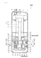
- a rotary compressor 100 of the embodiment includes a hermetic container 1, a motor 2, a compressing mechanism 102 and a shaft 4.
- the compressing mechanism 102 is placed at a lower location in the hermetic container 1.
- the motor 2 is placed in the hermetic container 1 at a location above the compressing mechanism 102.
- the compressing mechanism 102 and the motor 2 are connected to each other through the shaft 4.
- a terminal 21 for supplying electricity to the motor 2 is provided on an upper portion of the hermetic container 1 2.
- An oil reservoir 22 for retaining lubricant oil is formed in a bottom of the hermetic container 1.
- the motor 2 is composed of a stator 17 and a rotor 18.
- the stator 17 is fixed to an inner wall of the hermetic container 1.
- the rotor 18 is fixed to the shaft 4.
- the rotor 18 and the shaft 4 are driven and rotated by the motor 2.
- the upper portion of the hermetic container 1 is provided with a discharge pipe 11.
- the discharge pipe 11 penetrates the upper portion of the hermetic container 1 and opens toward an interior space 13 of the hermetic container 1.
- the discharge pipe 11 functions as a discharge flow path through which refrigerant compressed by the compressing mechanism 102 is introduced to outside of the hermetic container 1.
- the rotary compressor 100 When the rotary compressor 100 operates, the interior space 13 of the hermetic container 1 is filled with compressed refrigerant. That is, the rotary compressor 100 is a high pressure shell-type compressor. According to the high pressure shell-type rotary compressor 100, since it is possible to cool the motor 2 by refrigerant, it is possible to expect that motor efficiency is enhanced.
- the compressing mechanism 102 is operated by the motor 2 to compress refrigerant. More specifically, the compressing mechanism 102 includes a first compressing block 3, a second compressing block 30, an upper bearing member 6, a lower bearing member 7, a middle plate 38, a first closing member 9 (first muffler member) and a second closing member 10 (second muffler member). Refrigerant is compressed by the first compressing block 3 or the second compressing block 30. The first compressing block 3 and the second compressing block 30 are immersed in oil stored in the oil reservoir 22. In this embodiment, the first compressing block 3 is composed of parts which are in common with parts configuring the second compressing block 30. Therefore, the first compressing block 3 has the same suction capacity as that of the second compressing block 30.
- the first compressing block 3 is composed of a first cylinder 5, a first piston 8, a first vane 32, a first suction port 19, a first discharge port 40 and a first spring 36.
- the second compressing block 30 is composed of a second cylinder 15, a second piston 28, a second vane 33, a second suction port 20, a second discharge port 41 and a second spring 37.
- the first cylinder 5 and the second cylinder 15 are concentrically placed.
- the shaft 4 includes a first eccentric portion 4a and a second eccentric portion 4b.
- the first eccentric portion 4a and the second eccentric portion 4b project outward in a radial direction of the shaft 4.
- the first piston 8 and the second piston 28 are placed in the first cylinder 5 and the second cylinder 15, respectively.
- the first piston 8 is mounted on the first eccentric portion 4a.
- the second piston 28 is mounted on the second eccentric portion 4b.
- a first vane groove 34 and a second vane groove 35 are formed in the first cylinder 5 and the second cylinder 15, respectively.
- a position of the first vane groove 34 matches with a position of the second vane groove 35 in a rotation direction of the shaft 4.
- the first eccentric portion 4a projects in a direction which is 180° opposite from a projecting direction of the second eccentric portion 4b. That is, a phase difference between the first piston 8 and the second piston 28 is 180°. This configuration exerts an effect for reducing vibration and noise.
- the upper bearing member 6 (first end plate member) is mounted on the first cylinder 5 such that a first cylinder chamber 25 is formed between an inner peripheral surface of the first cylinder 5 and an outer peripheral surface of the first piston 8.
- the lower bearing member 7 (second end plate member) is mounted on the second cylinder 15 such that a second cylinder chamber 26 is formed between an inner peripheral surface of the second cylinder 15 and an outer peripheral surface of the second piston 28. More specifically, the upper bearing member 6 is mounted on an upper portion of the first cylinder 5, and the lower bearing member 7 is mounted on a lower portion of the second cylinder 15.
- the middle plate 38 is placed between the first cylinder 5 and the second cylinder 15.
- the first suction port 19 and the second suction port 20 are formed in the first cylinder 5 and the second cylinder 15, respectively.
- the first suction port 19 and the second suction port 20 open toward the first cylinder chamber 25 and the second cylinder chamber 26, respectively.
- a first suction pipe 14 and a second suction pipe 16 are connected to the first suction port 19 and the second suction port 20, respectively.
- the first discharge port 40 and the second discharge port 41 are formed in the upper bearing member 6 and the lower bearing member 7, respectively.
- the first discharge port 40 and the second discharge port 41 open toward the first cylinder chamber 25 and the second cylinder chamber 26, respectively.
- the first discharge port 40 is provided with a first discharge valve 43 to open and close the first discharge port 40.
- the first discharge valve 43 is composed of a thin first valve 43a, a first valve stop 43b and a first fixing tool 43c.
- the first valve 43a adjusts a discharge amount of refrigerant.
- the first valve stop 43b restricts motion of the first valve 43a.
- the first fixing tool 43c fixes the first valve 43a and the first valve stop 43b.
- the second discharge port 41 is provided with a second discharge valve 44 to open and close the second discharge port 41.
- the second discharge valve 44 is composed of a thin second valve 44a, a second valve stop 44b and a second fixing tool 44c.
- the second valve 44a adjusts a discharge amount of refrigerant.
- the second valve stop 44b restricts motion of the second valve 44a.
- the second fixing tool 44c fixes the second valve 44a and the second valve stop 44b.
- the first vane 32 (blade) is placed in the first vane groove 34 such that the first vane 32 can slide therein.
- the first vane 32 partitions the first cylinder chamber 25 along a circumferential direction of the first piston 8. According to this, the first cylinder chamber 25 is partitioned into a first suction chamber 25a and a first discharge chamber 25b.
- the second vane 33 (blade) is placed in the second vane groove 35 such that the second vane 33 can slide therein.
- the second vane 33 partitions the second cylinder chamber 26 along a circumferential direction of the second piston 28. According to this, the second cylinder chamber 26 is partitioned into a second suction chamber 26a and a second discharge chamber 26b.
- the first suction port 19 and the first discharge port 40 are located on left and right sides of the first vane 32, respectively.
- the second suction port 20 and the second discharge port 41 are located on left and right sides of the second vane 33.
- Refrigerant to be compressed is supplied to the first cylinder chamber 25 (first suction chamber 25a) through the first suction port 19.
- Refrigerant to be compressed is supplied to the second cylinder chamber 26 (second suction chamber 26a) through the second suction port 20.
- Refrigerant compressed in the first cylinder chamber 25 pushes and opens the first discharge valve 43, and is discharged from the first discharge chamber 25b through the first discharge port 40.
- Refrigerant compressed in the second cylinder chamber 26 pushes and opens the second discharge valve 44, and is discharged from the second discharge chamber 26b through the second discharge port 41.
- the first piston 8 and the first vane 32 may be composed of a single part, i.e., a swing piston.
- the second piston 28 and the second vane 33 may be composed of a single part, i.e., a swing piston.
- the first vane 32 and the second vane 33 may be coupled to the first piston 8 and the second piston 28, respectively.
- the first spring 36 and the second spring 37 are placed behind the first vane 32 and the second vane 33, respectively.
- the first spring 36 and the second spring 37 respectively push the first vane 32 and the second vane 33 toward a center of the shaft 4.
- a rear portion of the first vane groove 34 and a rear portion of the second vane groove 35 are in communication with the interior space 13 of the hermetic container 1. Therefore, pressure in the interior space 13 of the hermetic container 1 is applied to a back surface of the first vane 32 and a back surface of the second vane 33.
- Lubricant oil stored in the oil reservoir 22 is supplied to the first vane groove 34 and the second vane groove 35.
- Refrigerant discharged from the first discharge chamber 25b through the first discharge port 40 can stay in a refrigerant discharge space 51.
- the first closing member 9 is mounted on the upper bearing member 6 (first end plate member) such that the refrigerant discharge space 51 is formed on the opposite side from the first cylinder chamber 25. More specifically, the first closing member 9 is mounted on an upper portion of the upper bearing member 6 such that the refrigerant discharge space 51 is formed above the upper bearing member 6.
- the first discharge valve 43 is covered with the first closing member 9.
- a discharge port 9a is formed in the first closing member 9 for guiding refrigerant from the refrigerant discharge space 51 into the interior space 13 of the hermetic container 1.
- Refrigerant discharged from the second discharge chamber 26b through the second discharge port 41 can stay in a refrigerant discharge space 52.
- the second closing member 10 is mounted on the lower bearing member 7 (second end plate member) such that the refrigerant discharge space 52 is formed on the opposite side from the second cylinder chamber 26. More specifically, the second closing member 10 is mounted on a lower portion of the lower bearing member 7 such that the refrigerant discharge space 52 is formed below the lower bearing member 7.
- the second discharge valve 44 is covered with the second closing member 10.
- the refrigerant discharge spaces 51 and 52 function as flow paths for refrigerant.
- the shaft 4 penetrates a central portion of the first closing member 9 and a central portion of the second closing member 10. The shaft 4 is supported by the upper bearing member 6 and the lower bearing member 7. According to this, the shaft 4 can rotate.
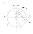
- the refrigerant discharge space 52 is composed of a possession space (space formed by minimum projection surface) when the second valve stop 44b, the penetrating flow path 46 and a passage 45 which brings the second discharge port 41 and the penetrating flow path 46 into communication with each other are projected in an axial direction of the shaft 4 as shown in Figs. 4 and 5 .
- the second valve stop 44b and the second valve 44a are fixed to each other through a rivet. They may be fixed to each other through a bolt instead of the rivet.
- the refrigerant discharge space 52 includes a space (escape portion) 47, and a device which fixes the second valve 44a and the second valve stop 44b to each other can be inserted into the space 47. According to this, since it becomes easy to fix the second valve stop 44b and the second valve 44a to each other through a rivet or a bolt, mass productivity is enhanced.
- an escape portion 47, the passage 45 and the penetrating flow path 46 may integrally formed together in the refrigerant discharge space 52. According to this, a flow of high pressure gas becomes excellent, and pressure loss is reduced.
- the refrigerant discharge space 52 is in communication with the refrigerant discharge space 51 through a penetrating flow path 46.
- the penetrating flow path 46 penetrates the lower bearing member 7, the second cylinder 15, the middle plate 38, the first cylinder 5 and the upper bearing member 6 in a direction parallel to a rotation axis of the shaft 4.
- Refrigerant compressed by the second compressing block 30 merges with refrigerant compressed by the first compressing block 3 in an interior space of the first closing member 9, i.e., in the refrigerant discharge space 51.
- a cross sectional area (area of flow path) of the penetrating flow path 46 is greater than a cross sectional area (area of flow path) of the second discharge port 41. According to this, it is possible to prevent pressure loss from increasing.
- a first reference plane H1, a second reference plane H2 and a third reference plane H3 are defined as follows.
- a plane which includes a center axis O 1 of the second cylinder 15 and a center of the second vane 33 when the second vane 33 most projects toward the center axis O 1 of the second cylinder 15 is defined as the first reference plane H1.
- the first reference plane H1 passes through a center of the second vane groove 35.
- a plane which includes the center axis O 1 and which is perpendicular to the first reference plane H1 is defined as the second reference plane H2.
- a plane which includes a center of the second suction port 20 and the center axis O 1 is defined as the third reference plane H3.
- the center axis O 1 of the second cylinder 15 substantially matches with the rotation axis of the shaft 4 and a center axis of the first cylinder 5.
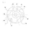
- the compressing mechanism 102 further includes an oil retaining section 53.
- the oil retaining section 53 is formed on the same side as the second suction port 20 as viewed from the first reference plane H1 and on the opposite side from the second cylinder chamber 26 while sandwiching the lower bearing member 7 between the oil retaining section 53 and the second cylinder chamber 26. More specifically, the oil retaining section 53 is in contact with a lower surface of the lower bearing member 7.
- the oil retaining section 53 is configured such that oil stored in the oil reservoir 22 is taken into the oil retaining section 53 and a flow of the oil which is taken is suppressed more than a flow of oil in the oil reservoir 22.
- the flow of oil in the oil retaining section 53 is slower than the flow of oil in the oil reservoir 22.
- an oil surface in the oil reservoir 22 is located higher than a lower surface of the first cylinder 5.
- the oil surface in the oil reservoir 22 is higher than an upper surface of the first cylinder 5 and lower than a lower surface of the motor 2 during operation of the rotary compressor.
- the second cylinder 15, the lower bearing member 7 and the second closing member 10 are immersed in oil in the oil reservoir 22. Therefore, oil in the oil reservoir 22 can flow into the oil retaining section 53.
- Refrigerant to be compressed is in a low temperature and low pressure state.
- compressed refrigerant is in a high temperature and high pressure state.
- a specific temperature distribution is generated in the lower bearing member 7. More specifically, when the lower bearing member 7 is divided into a suction-side portion and a discharge-side portion, temperature of the suction-side portion is relatively low, and temperature of the discharge-side portion is relatively high.
- the lower bearing member 7 is divided into a suction-side portion and a discharge-side portion by the first reference plane H1.
- the suction-side portion includes a portion directly below the second suction port 20, and the second discharge port 41 is provided in the discharge-side portion.
- the oil retaining section 53 is formed on the same side as the second suction port 20 as viewed from the first reference plane H1.
- the oil retaining section 53 is in contact with a lower surface of the lower bearing member 7.
- oil retained by the oil retaining section 53 functions as heat insulating material, it is possible to restrain heat of refrigerant (compressed refrigerant) of the refrigerant discharge space 52 from moving toward refrigerant (sucked refrigerant) sucked into the second cylinder chamber 26 through the lower bearing member 7. Even if another member is placed between the oil retaining section 53 and the lower surface of the lower bearing member 7, this other member can be regarded as a portion of the lower bearing member 7.
- a first recess formed in the lower bearing member 7 is closed by the second closing member 10.
- the oil retaining section 53 is formed. According to this structure, since it is possible to avoid increase in the thickness of the lower bearing member 7, it is possible to avoid increase in cost of parts, and this is also an advantage in reduction in weight of the rotary compressor 200.
- the oil retaining section 53 may be formed by closing the first recess by a member which is different from the second closing member 10.
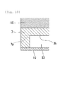
- the lower bearing member 7 is further provided with communication passages 7p.
- the communication passages 7p extend in a lateral direction to bring the oil reservoir 22 and the oil retaining section 53 into communication with each other. Oil in the oil reservoir 22 can flow into the oil retaining section 53 through the communication passages 7p (communication hole). If the plurality of communication passages 7p are formed, oil in the oil reservoir 22 can reliably flow into the oil retaining section 53. A size of each of the communication passages 7p is adjusted to such a necessary and sufficient size that oil in the oil reservoir 22 flows into the oil retaining section 53. Hence, a flow of oil in the oil retaining section 53 is slower than a flow of oil in the oil reservoir 22. Therefore, in the oil retaining section 53, oil forms relatively stable thermal stratification.
- the communication passages 7p are composed of small through holes.
- the communication passages 7p may be composed of other structures such as slits .
- upper ends of the communication passages 7p is located in a lower surface 7h of the lower bearing member 7, or exist at a location higher than the lower surface 7h of the lower bearing member 7. According to such a configuration, it is possible to prevent air or refrigerant from remaining in the oil retaining section 53.
- a second recess formed in the lower bearing member 7 is closed by the second closing member 10.
- the refrigerant discharge space 52 is formed. That is, the first recess which functions as the oil retaining section 53 and the second recess which functions as the refrigerant discharge space 52 are formed in the lower bearing member 7.
- the second closing member 10 is composed of a single plate-shaped member. An opening end surface of the first recess and an opening end surface of the second recess exist on the same plane so that both the first recess and the second recess are closed by the second closing member 10. Such a structure is extremely simple, and it is possible to avoid increase in the number of parts.
- the oil retaining section 53 is formed in a zone of a portion of a peripheral environment of the shaft 4, and the refrigerant discharge space 52 is formed in a zone of other portion of the peripheral environment of the shaft 4.
- the oil retaining section 53 is completely isolated from the refrigerant discharge space 52 by ribs 7k provided on the lower bearing member 7.
- Most of the refrigerant discharge space 52 is formed on the same side as the second discharge port 41 as viewed from the first reference plane H1.
- the oil retaining section 53 is formed on the same side of the second suction port 20 as viewed from the first reference plane H1. According to this positional relationship, it is possible to restrain heat of refrigerant discharged into the refrigerant discharge space 52 from moving toward refrigerant sucked into the second cylinder chamber 26.
- the first compressing block 3 may be omitted from a rotary compressor 200 shown in Fig. 8 . That is, this is a one-piston rotary compressor having only one cylinder.
- the present invention can be applied to the one-piston rotary compressor.
- the oil retaining section 53 may be formed in the upper bearing member 6 of the rotary compressor. According to the structure described with reference to Fig. 8 , it is also possible to form the oil retaining section 53 above the upper bearing member 6.
- the oil retaining section 53 may be formed on the upper side or on the lower side as viewed from the second cylinder chamber 26.
- the present invention is useful for a compressor of a refrigeration cycle device which can be utilized for an electric appliance such as a water heater, a hot-water heating device and an air conditioner.
Landscapes
- Engineering & Computer Science (AREA)
- Mechanical Engineering (AREA)
- General Engineering & Computer Science (AREA)
- Applications Or Details Of Rotary Compressors (AREA)
Applications Claiming Priority (2)
| Application Number | Priority Date | Filing Date | Title |
|---|---|---|---|
| JP2012142634 | 2012-06-26 | ||
| PCT/JP2013/003893 WO2014002457A1 (fr) | 2012-06-26 | 2013-06-21 | Compresseur rotatif |
Publications (3)
| Publication Number | Publication Date |
|---|---|
| EP2873864A1 true EP2873864A1 (fr) | 2015-05-20 |
| EP2873864A4 EP2873864A4 (fr) | 2015-10-21 |
| EP2873864B1 EP2873864B1 (fr) | 2020-09-09 |
Family
ID=49782651
Family Applications (1)
| Application Number | Title | Priority Date | Filing Date |
|---|---|---|---|
| EP13810070.6A Active EP2873864B1 (fr) | 2012-06-26 | 2013-06-21 | Compresseur rotatif |
Country Status (4)
| Country | Link |
|---|---|
| EP (1) | EP2873864B1 (fr) |
| JP (1) | JP6206776B2 (fr) |
| CN (1) | CN104428536B (fr) |
| WO (1) | WO2014002457A1 (fr) |
Cited By (2)
| Publication number | Priority date | Publication date | Assignee | Title |
|---|---|---|---|---|
| EP3321507A1 (fr) * | 2016-11-14 | 2018-05-16 | Fujitsu General Limited | Compresseur rotatif |
| US10458408B2 (en) | 2014-12-19 | 2019-10-29 | Fujitsu General Limited | Rotary compressor having communication path hole overlap with discharge chamber concave portion |
Families Citing this family (4)
| Publication number | Priority date | Publication date | Assignee | Title |
|---|---|---|---|---|
| WO2016098710A1 (fr) * | 2014-12-19 | 2016-06-23 | 株式会社富士通ゼネラル | Compresseur rotatif |
| JP6128194B2 (ja) * | 2015-10-30 | 2017-05-17 | 株式会社富士通ゼネラル | ロータリ圧縮機 |
| JP6112104B2 (ja) * | 2014-12-19 | 2017-04-12 | 株式会社富士通ゼネラル | ロータリ圧縮機 |
| CN114046250B (zh) * | 2021-11-03 | 2022-09-16 | 珠海格力电器股份有限公司 | 共振腔组件和压缩机 |
Family Cites Families (7)
| Publication number | Priority date | Publication date | Assignee | Title |
|---|---|---|---|---|
| JPH02140486A (ja) | 1988-11-22 | 1990-05-30 | Mitsubishi Electric Corp | 回転式圧縮機 |
| JPH11132177A (ja) * | 1997-10-30 | 1999-05-18 | Toshiba Corp | ロータリコンプレッサ |
| TWI301188B (en) * | 2002-08-30 | 2008-09-21 | Sanyo Electric Co | Refrigeant cycling device and compressor using the same |
| JP4007383B2 (ja) * | 2005-12-27 | 2007-11-14 | ダイキン工業株式会社 | ロータリ圧縮機 |
| KR100802023B1 (ko) * | 2006-11-01 | 2008-02-12 | 삼성전자주식회사 | 회전압축기 |
| JP4900081B2 (ja) * | 2007-06-25 | 2012-03-21 | ダイキン工業株式会社 | ロータリ圧縮機 |
| JP4948557B2 (ja) * | 2009-03-12 | 2012-06-06 | 三菱電機株式会社 | 多段圧縮機および冷凍空調装置 |
-
2013
- 2013-06-21 JP JP2014522422A patent/JP6206776B2/ja active Active
- 2013-06-21 CN CN201380034274.6A patent/CN104428536B/zh active Active
- 2013-06-21 WO PCT/JP2013/003893 patent/WO2014002457A1/fr active Application Filing
- 2013-06-21 EP EP13810070.6A patent/EP2873864B1/fr active Active
Cited By (4)
| Publication number | Priority date | Publication date | Assignee | Title |
|---|---|---|---|---|
| US10458408B2 (en) | 2014-12-19 | 2019-10-29 | Fujitsu General Limited | Rotary compressor having communication path hole overlap with discharge chamber concave portion |
| EP3321507A1 (fr) * | 2016-11-14 | 2018-05-16 | Fujitsu General Limited | Compresseur rotatif |
| US10563655B2 (en) | 2016-11-14 | 2020-02-18 | Fujitsu General Limited | Rotary compressor for compressing refrigerant using cylinder |
| AU2017251728B2 (en) * | 2016-11-14 | 2022-11-24 | Fujitsu General Limited | Rotary compressor |
Also Published As
| Publication number | Publication date |
|---|---|
| WO2014002457A1 (fr) | 2014-01-03 |
| JPWO2014002457A1 (ja) | 2016-05-30 |
| CN104428536B (zh) | 2017-05-10 |
| JP6206776B2 (ja) | 2017-10-04 |
| CN104428536A (zh) | 2015-03-18 |
| EP2873864B1 (fr) | 2020-09-09 |
| EP2873864A4 (fr) | 2015-10-21 |
Similar Documents
| Publication | Publication Date | Title |
|---|---|---|
| EP2873864A1 (fr) | Compresseur rotatif | |
| EP2796721B1 (fr) | Compresseur rotatif | |
| JP5631398B2 (ja) | ロータリ圧縮機及び冷凍サイクル装置 | |
| JPWO2009066416A1 (ja) | 膨張機一体型圧縮機 | |
| EP2873863B1 (fr) | Compresseur rotatif | |
| US8517702B2 (en) | Rotary compressor with enhanced sealing between mode switching device and chamber thereof | |
| US9568004B2 (en) | Rotary compressor | |
| US9512841B2 (en) | Rotary compressor with oil retaining portion | |
| JP2014231801A (ja) | ロータリ圧縮機 | |
| EP2871366B1 (fr) | Compresseur rotatif | |
| EP3184822B1 (fr) | Compresseur rotatif et dispositif de cycle de réfrigération | |
| JP4380734B2 (ja) | ロータリ圧縮機 | |
| JP6674223B2 (ja) | ロータリ圧縮機、ロータリ圧縮機の製造方法 | |
| JP2004308968A (ja) | 熱交換器 | |
| JP2014009612A (ja) | ロータリ圧縮機 | |
| JP5727348B2 (ja) | 気体圧縮機 | |
| JP2010261393A (ja) | 密閉型圧縮機、冷凍サイクル装置 | |
| JP2014015911A (ja) | ロータリ圧縮機 | |
| JP2014152749A (ja) | ロータリ圧縮機 | |
| KR20150031111A (ko) | 고압식 스크롤 압축기 | |
| JP6186593B2 (ja) | ロータリ圧縮機 | |
| JP2011163237A (ja) | スクロール圧縮機 | |
| JP2003293973A (ja) | 多段圧縮式ロータリコンプレッサ | |
| JP2006009756A (ja) | 圧縮システム及びそれを用いた冷凍装置 |
Legal Events
| Date | Code | Title | Description |
|---|---|---|---|
| PUAI | Public reference made under article 153(3) epc to a published international application that has entered the european phase |
Free format text: ORIGINAL CODE: 0009012 |
|
| 17P | Request for examination filed |
Effective date: 20150126 |
|
| AK | Designated contracting states |
Kind code of ref document: A1 Designated state(s): AL AT BE BG CH CY CZ DE DK EE ES FI FR GB GR HR HU IE IS IT LI LT LU LV MC MK MT NL NO PL PT RO RS SE SI SK SM TR |
|
| AX | Request for extension of the european patent |
Extension state: BA ME |
|
| DAX | Request for extension of the european patent (deleted) | ||
| RA4 | Supplementary search report drawn up and despatched (corrected) |
Effective date: 20150923 |
|
| RIC1 | Information provided on ipc code assigned before grant |
Ipc: F04C 29/06 20060101ALI20150917BHEP Ipc: F04C 18/356 20060101AFI20150917BHEP Ipc: F04C 23/00 20060101ALI20150917BHEP Ipc: F04C 29/04 20060101ALI20150917BHEP |
|
| STAA | Information on the status of an ep patent application or granted ep patent |
Free format text: STATUS: EXAMINATION IS IN PROGRESS |
|
| 17Q | First examination report despatched |
Effective date: 20180405 |
|
| GRAP | Despatch of communication of intention to grant a patent |
Free format text: ORIGINAL CODE: EPIDOSNIGR1 |
|
| STAA | Information on the status of an ep patent application or granted ep patent |
Free format text: STATUS: GRANT OF PATENT IS INTENDED |
|
| INTG | Intention to grant announced |
Effective date: 20190925 |
|
| GRAJ | Information related to disapproval of communication of intention to grant by the applicant or resumption of examination proceedings by the epo deleted |
Free format text: ORIGINAL CODE: EPIDOSDIGR1 |
|
| STAA | Information on the status of an ep patent application or granted ep patent |
Free format text: STATUS: EXAMINATION IS IN PROGRESS |
|
| INTC | Intention to grant announced (deleted) | ||
| GRAP | Despatch of communication of intention to grant a patent |
Free format text: ORIGINAL CODE: EPIDOSNIGR1 |
|
| STAA | Information on the status of an ep patent application or granted ep patent |
Free format text: STATUS: GRANT OF PATENT IS INTENDED |
|
| INTG | Intention to grant announced |
Effective date: 20200326 |
|
| GRAS | Grant fee paid |
Free format text: ORIGINAL CODE: EPIDOSNIGR3 |
|
| GRAA | (expected) grant |
Free format text: ORIGINAL CODE: 0009210 |
|
| STAA | Information on the status of an ep patent application or granted ep patent |
Free format text: STATUS: THE PATENT HAS BEEN GRANTED |
|
| AK | Designated contracting states |
Kind code of ref document: B1 Designated state(s): AL AT BE BG CH CY CZ DE DK EE ES FI FR GB GR HR HU IE IS IT LI LT LU LV MC MK MT NL NO PL PT RO RS SE SI SK SM TR |
|
| REG | Reference to a national code |
Ref country code: GB Ref legal event code: FG4D |
|
| REG | Reference to a national code |
Ref country code: AT Ref legal event code: REF Ref document number: 1311910 Country of ref document: AT Kind code of ref document: T Effective date: 20200915 Ref country code: CH Ref legal event code: EP |
|
| REG | Reference to a national code |
Ref country code: IE Ref legal event code: FG4D |
|
| REG | Reference to a national code |
Ref country code: DE Ref legal event code: R096 Ref document number: 602013072423 Country of ref document: DE |
|
| REG | Reference to a national code |
Ref country code: LT Ref legal event code: MG4D |
|
| PG25 | Lapsed in a contracting state [announced via postgrant information from national office to epo] |
Ref country code: GR Free format text: LAPSE BECAUSE OF FAILURE TO SUBMIT A TRANSLATION OF THE DESCRIPTION OR TO PAY THE FEE WITHIN THE PRESCRIBED TIME-LIMIT Effective date: 20201210 Ref country code: LT Free format text: LAPSE BECAUSE OF FAILURE TO SUBMIT A TRANSLATION OF THE DESCRIPTION OR TO PAY THE FEE WITHIN THE PRESCRIBED TIME-LIMIT Effective date: 20200909 Ref country code: HR Free format text: LAPSE BECAUSE OF FAILURE TO SUBMIT A TRANSLATION OF THE DESCRIPTION OR TO PAY THE FEE WITHIN THE PRESCRIBED TIME-LIMIT Effective date: 20200909 Ref country code: BG Free format text: LAPSE BECAUSE OF FAILURE TO SUBMIT A TRANSLATION OF THE DESCRIPTION OR TO PAY THE FEE WITHIN THE PRESCRIBED TIME-LIMIT Effective date: 20201209 Ref country code: SE Free format text: LAPSE BECAUSE OF FAILURE TO SUBMIT A TRANSLATION OF THE DESCRIPTION OR TO PAY THE FEE WITHIN THE PRESCRIBED TIME-LIMIT Effective date: 20200909 Ref country code: FI Free format text: LAPSE BECAUSE OF FAILURE TO SUBMIT A TRANSLATION OF THE DESCRIPTION OR TO PAY THE FEE WITHIN THE PRESCRIBED TIME-LIMIT Effective date: 20200909 Ref country code: NO Free format text: LAPSE BECAUSE OF FAILURE TO SUBMIT A TRANSLATION OF THE DESCRIPTION OR TO PAY THE FEE WITHIN THE PRESCRIBED TIME-LIMIT Effective date: 20201209 |
|
| REG | Reference to a national code |
Ref country code: AT Ref legal event code: MK05 Ref document number: 1311910 Country of ref document: AT Kind code of ref document: T Effective date: 20200909 |
|
| REG | Reference to a national code |
Ref country code: NL Ref legal event code: MP Effective date: 20200909 |
|
| PG25 | Lapsed in a contracting state [announced via postgrant information from national office to epo] |
Ref country code: LV Free format text: LAPSE BECAUSE OF FAILURE TO SUBMIT A TRANSLATION OF THE DESCRIPTION OR TO PAY THE FEE WITHIN THE PRESCRIBED TIME-LIMIT Effective date: 20200909 Ref country code: RS Free format text: LAPSE BECAUSE OF FAILURE TO SUBMIT A TRANSLATION OF THE DESCRIPTION OR TO PAY THE FEE WITHIN THE PRESCRIBED TIME-LIMIT Effective date: 20200909 Ref country code: PL Free format text: LAPSE BECAUSE OF FAILURE TO SUBMIT A TRANSLATION OF THE DESCRIPTION OR TO PAY THE FEE WITHIN THE PRESCRIBED TIME-LIMIT Effective date: 20200909 |
|
| PG25 | Lapsed in a contracting state [announced via postgrant information from national office to epo] |
Ref country code: CZ Free format text: LAPSE BECAUSE OF FAILURE TO SUBMIT A TRANSLATION OF THE DESCRIPTION OR TO PAY THE FEE WITHIN THE PRESCRIBED TIME-LIMIT Effective date: 20200909 Ref country code: EE Free format text: LAPSE BECAUSE OF FAILURE TO SUBMIT A TRANSLATION OF THE DESCRIPTION OR TO PAY THE FEE WITHIN THE PRESCRIBED TIME-LIMIT Effective date: 20200909 Ref country code: RO Free format text: LAPSE BECAUSE OF FAILURE TO SUBMIT A TRANSLATION OF THE DESCRIPTION OR TO PAY THE FEE WITHIN THE PRESCRIBED TIME-LIMIT Effective date: 20200909 Ref country code: SM Free format text: LAPSE BECAUSE OF FAILURE TO SUBMIT A TRANSLATION OF THE DESCRIPTION OR TO PAY THE FEE WITHIN THE PRESCRIBED TIME-LIMIT Effective date: 20200909 Ref country code: PT Free format text: LAPSE BECAUSE OF FAILURE TO SUBMIT A TRANSLATION OF THE DESCRIPTION OR TO PAY THE FEE WITHIN THE PRESCRIBED TIME-LIMIT Effective date: 20210111 Ref country code: NL Free format text: LAPSE BECAUSE OF FAILURE TO SUBMIT A TRANSLATION OF THE DESCRIPTION OR TO PAY THE FEE WITHIN THE PRESCRIBED TIME-LIMIT Effective date: 20200909 |
|
| PG25 | Lapsed in a contracting state [announced via postgrant information from national office to epo] |
Ref country code: AL Free format text: LAPSE BECAUSE OF FAILURE TO SUBMIT A TRANSLATION OF THE DESCRIPTION OR TO PAY THE FEE WITHIN THE PRESCRIBED TIME-LIMIT Effective date: 20200909 Ref country code: AT Free format text: LAPSE BECAUSE OF FAILURE TO SUBMIT A TRANSLATION OF THE DESCRIPTION OR TO PAY THE FEE WITHIN THE PRESCRIBED TIME-LIMIT Effective date: 20200909 Ref country code: ES Free format text: LAPSE BECAUSE OF FAILURE TO SUBMIT A TRANSLATION OF THE DESCRIPTION OR TO PAY THE FEE WITHIN THE PRESCRIBED TIME-LIMIT Effective date: 20200909 Ref country code: IS Free format text: LAPSE BECAUSE OF FAILURE TO SUBMIT A TRANSLATION OF THE DESCRIPTION OR TO PAY THE FEE WITHIN THE PRESCRIBED TIME-LIMIT Effective date: 20210109 |
|
| REG | Reference to a national code |
Ref country code: DE Ref legal event code: R097 Ref document number: 602013072423 Country of ref document: DE |
|
| PG25 | Lapsed in a contracting state [announced via postgrant information from national office to epo] |
Ref country code: SK Free format text: LAPSE BECAUSE OF FAILURE TO SUBMIT A TRANSLATION OF THE DESCRIPTION OR TO PAY THE FEE WITHIN THE PRESCRIBED TIME-LIMIT Effective date: 20200909 |
|
| PLBE | No opposition filed within time limit |
Free format text: ORIGINAL CODE: 0009261 |
|
| STAA | Information on the status of an ep patent application or granted ep patent |
Free format text: STATUS: NO OPPOSITION FILED WITHIN TIME LIMIT |
|
| 26N | No opposition filed |
Effective date: 20210610 |
|
| PG25 | Lapsed in a contracting state [announced via postgrant information from national office to epo] |
Ref country code: SI Free format text: LAPSE BECAUSE OF FAILURE TO SUBMIT A TRANSLATION OF THE DESCRIPTION OR TO PAY THE FEE WITHIN THE PRESCRIBED TIME-LIMIT Effective date: 20200909 Ref country code: DK Free format text: LAPSE BECAUSE OF FAILURE TO SUBMIT A TRANSLATION OF THE DESCRIPTION OR TO PAY THE FEE WITHIN THE PRESCRIBED TIME-LIMIT Effective date: 20200909 |
|
| PG25 | Lapsed in a contracting state [announced via postgrant information from national office to epo] |
Ref country code: IT Free format text: LAPSE BECAUSE OF FAILURE TO SUBMIT A TRANSLATION OF THE DESCRIPTION OR TO PAY THE FEE WITHIN THE PRESCRIBED TIME-LIMIT Effective date: 20200909 |
|
| PG25 | Lapsed in a contracting state [announced via postgrant information from national office to epo] |
Ref country code: MC Free format text: LAPSE BECAUSE OF FAILURE TO SUBMIT A TRANSLATION OF THE DESCRIPTION OR TO PAY THE FEE WITHIN THE PRESCRIBED TIME-LIMIT Effective date: 20200909 |
|
| REG | Reference to a national code |
Ref country code: CH Ref legal event code: PL |
|
| GBPC | Gb: european patent ceased through non-payment of renewal fee |
Effective date: 20210621 |
|
| REG | Reference to a national code |
Ref country code: BE Ref legal event code: MM Effective date: 20210630 |
|
| PG25 | Lapsed in a contracting state [announced via postgrant information from national office to epo] |
Ref country code: LU Free format text: LAPSE BECAUSE OF NON-PAYMENT OF DUE FEES Effective date: 20210621 |
|
| PG25 | Lapsed in a contracting state [announced via postgrant information from national office to epo] |
Ref country code: LI Free format text: LAPSE BECAUSE OF NON-PAYMENT OF DUE FEES Effective date: 20210630 Ref country code: IE Free format text: LAPSE BECAUSE OF NON-PAYMENT OF DUE FEES Effective date: 20210621 Ref country code: GB Free format text: LAPSE BECAUSE OF NON-PAYMENT OF DUE FEES Effective date: 20210621 Ref country code: CH Free format text: LAPSE BECAUSE OF NON-PAYMENT OF DUE FEES Effective date: 20210630 |
|
| PG25 | Lapsed in a contracting state [announced via postgrant information from national office to epo] |
Ref country code: FR Free format text: LAPSE BECAUSE OF NON-PAYMENT OF DUE FEES Effective date: 20210630 |
|
| PG25 | Lapsed in a contracting state [announced via postgrant information from national office to epo] |
Ref country code: BE Free format text: LAPSE BECAUSE OF NON-PAYMENT OF DUE FEES Effective date: 20210630 |
|
| PG25 | Lapsed in a contracting state [announced via postgrant information from national office to epo] |
Ref country code: HU Free format text: LAPSE BECAUSE OF FAILURE TO SUBMIT A TRANSLATION OF THE DESCRIPTION OR TO PAY THE FEE WITHIN THE PRESCRIBED TIME-LIMIT; INVALID AB INITIO Effective date: 20130621 |
|
| PG25 | Lapsed in a contracting state [announced via postgrant information from national office to epo] |
Ref country code: CY Free format text: LAPSE BECAUSE OF FAILURE TO SUBMIT A TRANSLATION OF THE DESCRIPTION OR TO PAY THE FEE WITHIN THE PRESCRIBED TIME-LIMIT Effective date: 20200909 |
|
| PGFP | Annual fee paid to national office [announced via postgrant information from national office to epo] |
Ref country code: DE Payment date: 20230620 Year of fee payment: 11 |
|
| PG25 | Lapsed in a contracting state [announced via postgrant information from national office to epo] |
Ref country code: MK Free format text: LAPSE BECAUSE OF FAILURE TO SUBMIT A TRANSLATION OF THE DESCRIPTION OR TO PAY THE FEE WITHIN THE PRESCRIBED TIME-LIMIT Effective date: 20200909 |