EP2873344B1 - Meuble doté d'un pied réglable en hauteur - Google Patents
Meuble doté d'un pied réglable en hauteur Download PDFInfo
- Publication number
- EP2873344B1 EP2873344B1 EP13405130.9A EP13405130A EP2873344B1 EP 2873344 B1 EP2873344 B1 EP 2873344B1 EP 13405130 A EP13405130 A EP 13405130A EP 2873344 B1 EP2873344 B1 EP 2873344B1
- Authority
- EP
- European Patent Office
- Prior art keywords
- pin
- telescopic element
- axis
- telescopic
- movement
- Prior art date
- Legal status (The legal status is an assumption and is not a legal conclusion. Google has not performed a legal analysis and makes no representation as to the accuracy of the status listed.)
- Active
Links
- 230000033001 locomotion Effects 0.000 claims description 49
- 238000006073 displacement reaction Methods 0.000 claims description 5
- 238000005096 rolling process Methods 0.000 claims description 3
- 230000005540 biological transmission Effects 0.000 description 2
- 239000000969 carrier Substances 0.000 description 2
- 230000000295 complement effect Effects 0.000 description 2
- 230000006835 compression Effects 0.000 description 1
- 238000007906 compression Methods 0.000 description 1
- 230000000694 effects Effects 0.000 description 1
- NJPPVKZQTLUDBO-UHFFFAOYSA-N novaluron Chemical compound C1=C(Cl)C(OC(F)(F)C(OC(F)(F)F)F)=CC=C1NC(=O)NC(=O)C1=C(F)C=CC=C1F NJPPVKZQTLUDBO-UHFFFAOYSA-N 0.000 description 1
- 230000036316 preload Effects 0.000 description 1
- 238000004904 shortening Methods 0.000 description 1
- 230000003068 static effect Effects 0.000 description 1
- 230000001360 synchronised effect Effects 0.000 description 1
- 230000007704 transition Effects 0.000 description 1
- 230000001960 triggered effect Effects 0.000 description 1
Images


Classifications
-
- A—HUMAN NECESSITIES
- A47—FURNITURE; DOMESTIC ARTICLES OR APPLIANCES; COFFEE MILLS; SPICE MILLS; SUCTION CLEANERS IN GENERAL
- A47B—TABLES; DESKS; OFFICE FURNITURE; CABINETS; DRAWERS; GENERAL DETAILS OF FURNITURE
- A47B9/00—Tables with tops of variable height
- A47B9/08—Tables with tops of variable height with clamps acting on vertical rods
- A47B9/083—Tables with tops of variable height with clamps acting on vertical rods with spreading means inside a tube
-
- A—HUMAN NECESSITIES
- A47—FURNITURE; DOMESTIC ARTICLES OR APPLIANCES; COFFEE MILLS; SPICE MILLS; SUCTION CLEANERS IN GENERAL
- A47B—TABLES; DESKS; OFFICE FURNITURE; CABINETS; DRAWERS; GENERAL DETAILS OF FURNITURE
- A47B9/00—Tables with tops of variable height
- A47B9/20—Telescopic guides
Definitions
- the invention relates to furniture, especially tables, with at least one height-adjustable leg.
- Height-adjustable furniture in particular height-adjustable worktables, are known in the art.
- US 5,706,739 (Ergotech Inc.) describes a height-adjustable workbench in which a work surface is supported on two rectangular telescopic legs.
- the telescopic legs each have two telescopic elements, which can be moved against each other.
- a crank a shaft is driven, which has in each case a gear in the region of the two telescopic legs.
- the gears engage in a rack, which is arranged in the two upper telescopic elements.
- the telescopic elements are mounted on an arrangement of four rollers together.
- a locking device in which a slider blocks the rotation of one of the gears, the telescopic elements can be fixed relative to each other.
- WO 2006/066116 discloses mechanically height-adjustable tables, especially with only one foot, wherein a safety lock and preferably an adjustable counterweight are present.
- the tables comprise a two-part telescopic leg with a force compensation mechanism arranged therein, which comprises inter alia a wire whose ends are fastened to the first and second telescopic part and a force generator whose pretension can be adjusted.
- the telescopic parts are mounted on rollers with each other, whereby the friction is reduced.
- a lock is provided which comprises a threaded rod and a cooperating sleeve.
- the sleeve By means of a corresponding mechanism actuated by a lever via an actuating cable, the sleeve can be fixed relative to the threaded rod with respect to its rotation.
- a safety device By means of two compression springs also a safety device is provided, which completely prevents a height adjustment at too high forces acting on the table top.
- LU 90876 (Deceuninck NV) relates to a height-adjustable support column for supporting a tabletop, which is designed as a two-part telescope.
- the upper telescopic part is a mounting plate extending within the column connected to the at least one spring-loaded locking plate is pivotally coupled, so that a lip thereof can engage in one of a plurality of superimposed recesses in the lower telescopic part.
- means for pivoting the locking plate are present to allow a displacement of the two telescopic parts to each other.
- the latter means comprise, in particular, a cable connected to the securing plate, which extends in the column up to its upper end and then further outwards and is provided at its corresponding end with an actuating member.
- each support leg consists of an outer tube and at least one relatively displaceable inner tube.
- the inner tube is guided via guide rings axially displaceable in the outer tube.
- the support legs are each about a tension member in their length vergrösserbar.
- the end of a tension member is attached to a cap of the inner tube.
- the tension members of all support legs are guided to a tractor unit and run there over pulleys to a rotatably mounted drum with helical grooves for receiving the tension members.
- the drum can be arranged with a vertical axis below the worktop. It is powered by hand or motor to adjust the height of the table.
- the support legs can be locked in a specific height.
- DE 198 56 864 discloses a table frame with an upper frame, which is mounted on at least two telescopic guides with respect to a pedestal and adjustable in height and locked, the adjustment is done by manually operable and synchronized threaded spindles.
- gears are arranged, which are connected via a chain or a toothed belt with a drive gear.
- an actuating mechanism is coupled with locking device.
- a drive drum is connected to the drive gear, on whose circumference a drive jaw engages, which is actuated via a cable against the force of a spring in the circumferential direction of a pull rod.
- a brake shoe for releasably engages to lock.
- a coil spring coupled to the drive gear or the drive drum, wherein the attachment point of the coil spring and thus the bias of which is adjustable by an adjustable fastener.
- the height-adjustable tables known in the prior art have the disadvantage that due to the roller guides the telescopic legs must be dimensioned relatively large and that the known locking devices which fix the telescopic legs in a certain length, a tabletop can only be limited movement stable lock.
- the object of the invention is to provide a the technical field mentioned above belonging furniture with Almostnver constituem leg, which has a slim as possible embodiment of the leg and a smooth height adjustment, the furniture can be locked motion stable at a certain height.
- a piece of furniture has at least one length-adjustable leg which comprises a first telescopic element, which is designed as a hollow body, and a second telescopic element, which is mounted linearly displaceably along a first axis within the first telescopic element.
- a locking device is arranged on the second telescopic element.
- the locking device has at least one first pin, which prevents the movement of the first telescopic element relative to the second telescopic element by frictional connection or positive locking via an actuating device from a first position in which the at least one first pin, in a second position in which the displacement is not is prevented, is movable.
- the locking device has at least one second pin, which is pressed by the actuating device from a first state in which the at least one second pin is pressed against an inner side of a wall of the first telescopic element to the second telescopic element relative to the first To clamp Telskopelement, and a second state in which the at least one second pin is spaced from the wall of the first telescopic element, is movable.
- the furniture is preferably a table, in particular a work table, with a substantially flat work surface.
- the furniture may be a chair, sideboard, shelf, carcass or the like.
- all types of furniture which are designed adjustable in height, can be configured according to the present invention.
- the at least one length-adjustable leg preferably has a round cross-section.
- the at least one length-adjustable leg can also have a square, rectangular or any polygonal cross-section.
- the furniture preferably has two length-adjustable legs. Depending on the size or design of the furniture this may also have more than two adjustable legs, in particular four or more adjustable legs. Alternatively, however, a piece of furniture may also have only a single length-adjustable leg, for. B. if the furniture is a stool, bistro table or similar.
- the at least one height-adjustable leg further preferably has a boom or a base plate to the height-adjustable leg motion safe on a surface, such. B. the floor of a room to ask.
- the second telescopic element is arranged in the first telescopic element and movable relative thereto along a first axis. Accordingly, the first telescopic element and the second telescopic element overlap in the region in which the second telescopic element is received within the first telescopic element.
- the first axis is arranged so that it is substantially normal to the surface of the ground on which the furniture stands.
- the relative movement of the two telescopic elements of the at least one height-adjustable leg is preferably driven by a corresponding mechanism.
- the furniture preferably has, for example, a hand crank with the aid of which a user can move the two telescopic elements of the at least one length-adjustable leg relative to one another in both directions along the first axis.
- the transmission of the movement of the crank on at least one of the telescopic elements is preferably carried out via a cable.
- the mechanism additionally has a device with which the weight of the furniture is compensated, such as a counter to the direction of the self-weight force acting spring force to allow the smoothest possible length adjustment of the at least one length-adjustable leg.
- this spring force can be varied over a change in length of a spring, for example, via a crank in order to allow an individual adjustment of the compensation of the dead weight force.
- an electric motor may be provided which allows a particularly simple length adjustment of at least one leg adjustable in length.
- no mechanism can be provided and the length adjustment purely by lifting the furniture done by a user.
- the at least one first pin engages preferably in the sense of a positive connection in a structure of the first telescopic element.
- the at least one first pin has a surface with teeth, which engages in a corresponding surface within the first telescopic element with complementary teeth.
- the at least one first pin can also prevent a relative displacement of the telescopic elements against one another via a pure frictional connection.
- a surface of the at least one first pin and a surface of the first telescopic element, which is engaged by the at least one first pin are provided with surfaces which have a high static friction relative to each other.
- the locking device has more than one first pin, in particular two first pins, which can enter into a force or positive engagement with the first telescopic element, for example, on two opposite sides of the second telescopic element.
- the at least one first pin is preferably from the first telescopic element or a surface within the first telescopic element spaced, whereby no force or positive connection with the first telescopic element.
- the second telescopic element can be moved freely along the first axis in both directions relative to the first telescopic element.
- a stop is preferably provided which limits the movement of the second telescopic element relative to the first telescopic element. Accordingly, this limitation defines the maximum length of the at least one length-adjustable leg. Similarly, a further stop can be provided to define a maximum overlap of the second telescopic element with the first telescopic element. This second stop thus defines the shortest length of the adjustable leg.
- the actuating device is preferably designed such that the at least one first pin and the at least one second pin of all length-adjustable legs can be actuated at the same time. This simplifies the handling of the height adjustment of a piece of furniture according to the invention.
- the at least one second pin presses in the first state against an inner side of the wall of the first telescopic element. Due to the force with which the at least one second pin presses on the first telescopic element, the second telescopic element braces relative to the first telescopic element. This means that a possible clearance between the first and the second telescopic element is prevented by the tension of the two telescopic elements against each other. As a result, the second telescopic element is fixed against movement with respect to the first telescopic element. Any lateral movements of the furniture caused by a play between the two telescopic elements can thus be reliably prevented.
- the solution according to the invention also provides a secure movement fixation, but at a much smaller footprint, since the roles are replaced by space-saving bearings can. This allows the creation of furniture with slim, yet motion-safe, adjustable legs.
- the at least one first pin is mounted in the locking device such that it is movable along a second axis, which is substantially at right angles to the first axis.
- a movement of the actuating device against a first restoring force in a first direction along the first axis is converted from a locked position to an unlocked position via a first slotted guide in a movement of the at least one first pin along the second axis from the first position to the second position ,
- a movement of the actuating device along the first axis ie along the axis in which the relative movement of the two telescopic elements to each other, can be particularly simple and reliable in a movement along a second axis, which is substantially at right angles to the second axis, implement.
- Substantially at right angles in this application means an included angle of 90 ° plus / minus a maximum deviation of 5 °.
- the storage of the at least one first pin in the locking device is preferably carried out by arranging the at least one first pin in a linear guide, in particular in a groove or recess of the locking device.
- the at least one first pin is automatically pushed into the first position.
- the actuating device can be designed such that it exerts a tensile force only in the first direction, since the movement of the actuating device in the second direction and thus the movement of the at least one first pin from the second position to the first position by the restoring force he follows.
- the restoring force of at least one first pin can be acted upon by the restoring force of at least one first pin with a sufficiently high force to ensure a reliable positive or non-positive connection with the first telescopic element.
- the actuator has a locked and unlocked position, wherein in the unlocked position the at least one first pin is in the second position and the at least one second pin is in the second state while the pins are in the locked position in the first position in the first state.
- the length of the at least one adjustable leg can be changed, i. H. move the two telescopic elements relative to each other.
- the actuator is in the locked state, the two telescopic elements are locked together and the length of the adjustable leg can not be changed.
- the actuator is preferably operated by a lever so that it can be brought from the locked position to the unlocked position.
- the actuating device preferably has a transmission element, such as a wire, a chain or the like, with which a force can be transmitted at least to the first link guide.
- the at least one second pin is mounted in the locking device such that it is movable along a third axis, which is substantially at right angles to the first axis and preferably at right angles to the second axis. Movement of the actuator against a second return force acting on the second pin from the locked position to the unlocked position via a second slotted guide is translated into movement of the at least one second pin along the third axis from the first state to the second state.
- a maximum possible tension of the two telescopic elements to each other can be achieved. Due to the preferred arrangement of the third axis essentially in a right Angle to the second axis, along which moves the at least one second pin, improved movement safety can be achieved, as if the at least one second pin would move along the same second axis as the at least one first pin. Since the positive or positive connection of the at least one first pin already ensures a certain degree of movement safety along the second axis, a movement-secure locking of the second telescopic element to the first telescopic element can additionally be achieved along the third axis by the clamping. Overall, it is thus possible to realize a locking of the two telescopic elements which is secure against movement in all directions relative to one another.
- the storage of the at least one second pin in the locking device is preferably carried out by arranging the at least one second pin in a linear guide, in particular in a groove or recess of the locking device.
- the at least one second pin is moved over the same actuator as the at least one first pin. This allows the simplest possible locking and clamping of the two telescopic elements to each other.
- the second restoring force can act directly on the at least one second pin, but preferably acts via the second linearly displaceable plate indirectly via the second slotted guide on the at least one second pin.
- the second restoring force is preferably designed as a spring, in particular as a spiral spring.
- the second restoring force may also be formed as a spiral spring or as an elastic element.
- the furniture has a single second pin.
- the first slotted guide is formed as a linearly movable along the first axis first plate on which a first groove is formed. In this first groove a arranged on the first pin first pin is guided.
- the second slotted guide is preferably designed as a second groove introduced in a second plate which is linearly movable along the first axis. In this second groove arranged on the at least one second pin second pin is guided.
- the second slotted guide is formed as a curve, wherein this curve is configured such that upon movement of the at least one second pin from the second state to the first state, the curve first has a first region with a greater slope than in a second, subsequent region ,
- the at least one second pin can initially be moved relatively quickly along the third axis over the greater pitch until it comes into contact with the inside of the wall of the first telescopic element.
- smaller slope of the curve of the at least one second pin is then pressed with a smaller movement speed, but with a greater force against the inside of the wall to allow the tension of the two telescopic elements.
- At the same time can be achieved in the second groove by the design of the curve with the two areas of different pitch self-locking of the second pin.
- slope in the sense of the present application, the angle is understood, which takes the curve of the second link guide relative to the first axis. The larger this angle, the greater the slope of the curve.
- the actuating device has a driver, which abuts a stop surface of the second plate upon movement of the actuating device from the locked position to the unlocked position.
- the driver Upon movement of the actuator from the locked to the unlocked state in the first direction along the first axis, the driver strikes the abutment surface of the first plate. As a result, the second slide guide is pulled by the actuating device in the first direction, whereby a movement of the second pin and thus of the at least one second pin from the first state to the second state.
- the driver may disengage from the stop surface and thus move the actuator further in the second direction than the second plate. This makes it possible to at least partially decouple the movement of the at least one first pin, which is preferably also moved via the same actuating device, from the second to the first position from the movement of the at least one second pin from the second state to the first state.
- the at least one first pin is preferably also connected via a stop surface with the actuating device.
- the locking device is arranged within the second telescopic element, wherein in a wall of the second telescopic element at least one opening is provided, through which the at least one second pin is movable therethrough.
- an opening in the wall can also be provided for the at least one first pin, so that this at least one first pin can enter through the wall of the second telescopic element through the first telescopic element a non-positive or positive connection.
- the actuator is designed as a Bowden cable.
- a Bowden cable can also be deflected by means of rollers or the like, for example in order to be able to arrange a lever designed for actuating the Bowden cable outside the at least one leg, in particular below a table top.
- At least one sliding bearing is arranged, which cooperates with a wall on an outer side of the second telescopic element.
- the arrangement of a sliding bearing, the at least one adjustable leg can be made very slim, which gives the furniture overall an appealing aesthetic effect.
- the first end of the first telescopic element is the upper end thereof.
- the first telescopic element represents the lower part and the second telescopic element represents the upper part of the at least one length-adjustable leg.
- the second telescopic element has at least one roller bearing at a second end, which interacts with the inside of the wall of the first telescopic element.
- At least two rollers which are located on opposite sides of the second telescopic element, are particularly preferably used as roller bearings. These rollers are arranged such that their lateral surfaces touch the inner wall of the first telescopic element at least one point. The at least two rollers thus roll on the inside of the wall.
- the rolling bearing is arranged on the locking device.
- the second telescopic element is preferably arranged in the first telescopic element such that the second end of the second telescopic element lies in the first direction along the first axis below the first end of the first telescopic element.
- the second telescopic element is mounted at its second end via a roller bearing and in a region which lies in the first direction above the roller bearing, via a sliding bearing linearly displaceable within the first telescopic element.
- At least one arm is arranged, which extends from a second end to the first end of the first telescopic element, wherein the at least one first pin in the first position with the cantilever force or positively cooperates.
- the surface with which the at least one first pin co-operates in a force-locking or positive-locking manner can be separated from the inside of the wall of the first telescopic element.
- obstruction of the linear displacement movement of the second telescopic element within the first telescopic element is prevented by this surface.
- the arm extends at least partially into an interior of the second telescopic element.
- a guide can be arranged within the second telescopic element, which guide cooperates with the arm, in order to allow a particularly good linear guidance of the second telescopic element within the first telescopic element.
- the guide is formed in particular in the form of at least one guide groove or at least one half-ring, which (r) is slidably mounted along the cantilever.
- the FIG. 1 shows an inventive furniture in one embodiment as a table 1 with two length-adjustable legs 15.1, 15.2.
- the adjustable-length legs 15.1, 15.2 each comprise a first telescopic element 2.1, 2.2 and a second telescopic element 3.2, 3.2 received within the first telescopic element 2.1, 2.2 and mounted linearly displaceably.
- At a lower end of the first telescopic elements 2.1, 2.2 are 4.1, 4.2 arranged.
- the boom 4.1, 4.2 increase the stability of the tilting table 1 against the ground on which the table 1 stands.
- the two length-adjustable legs 15.1, 15.2 are connected to one another via a cross member 5 in an upper region of the first telescopic element 2.1, 2.2.
- two carriers 6.1, 6.2 are arranged, on which a table top (not shown) can be mounted. Between these carriers 6.1, 6.2 and below the table top, an adjusting mechanism is arranged, with which the second telescopic elements 3.1, 3.2 can be moved linearly relative to the first telescopic elements 2.1, 2.2.
- This adjustment mechanism has a drive pulley 8, around the circumference of which two wires 7.1, 7.2 can be rolled up.
- the wires 7.1, 7.2 are deflected via corresponding rollers and guided in the length-adjustable legs 15.1, 15.2.
- the table top can be made higher with the adjusting mechanism shown. Accordingly, unwinding of the wires 7.1, 7.2 causes a lowering of the table top.
- a counterweight spring 9 is a compensation of the dead weight of the table top. This allows a relatively smooth height adjustment of the table.
- the counterweight spring preferably has an adjusting arrangement with which the force exerted by the counterweight spring 9 can be changed by an extension or shortening of the counterweight spring 9.
- This adjustment arrangement has a hand crank 11, with which the length of the counterweight spring 9 can be adjusted via a spindle 10 in order to allow different preloads of the counterweight spring 9 to compensate for the dead weight.
- the drive pulley 8 with the wires 7.1, 7.2 is attached to the counterweight spring 9.
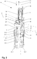
- FIG. 2 shows a three-dimensional view of a locking device 16 which cooperates with two cantilever pins 23.1, 23.2 of a cantilever of the first telescopic element 2.
- the two cantilever pins 23.1, 23.2 are connected to each other via a connecting element 24 at its upper end.
- a wire 7 of an adjusting mechanism is connected to the connecting element 24.
- the wire 7 is first guided parallel to the delivery pins 23.1, 23.2 to a deflection roller 27. About this guide roller 27 of the wire 7 is deflected by 180 ° and then guided parallel to a wall of the second telescopic element (not shown) through this to the adjusting mechanism.
- the locking device 16 is arranged at the second, lower end of the second telescopic element 3.
- the locking device 16 along the two boom pins 23.1, 23.2 out.
- four rollers are arranged at the lower end of the locking device 16. By means of the rollers 26.1, 26.2, the locking device 16 is guided linearly displaceable within the second telescopic element 3.
- a first pin 17 is arranged linearly displaceable between a first and a second position in the locking device 16. A movement of the first pin 17 from the first to the second position shown is made possible by movement of an actuating device 28, which is formed in the embodiment shown as a Bowden cable, in a first direction 33 along a first axis A.
- the actuator 28 is connected to a first in the direction A linearly displaceably mounted first plate 18.
- the first plate 18 has a first slide guide 19, which is formed as a groove. In the slotted guide 19, a first pin 20 is guided, which is connected to the first pin 17.
- the first slide guide 19 Via this first slide guide 19, a movement of the first plate 18, which is triggered by the actuator 28, in a linear movement of the first pin 17 along a second axis B, which is at a right angle to the first axis A, implemented.
- the first slide guide 19 is formed in the embodiment shown as a curve.
- first plate 18 engages a first coil spring 21, which opposite to the first direction 33, a restoring force in a second direction 34, which is opposite to the first direction 33, on the first plate 18 exerts.
- a restoring force in a second direction 34 which is opposite to the first direction 33, on the first plate 18 exerts.
- the first pin engages with a surface 22 with form-locking elements on the first boom pin 23.1.
- the first cantilever pin 23.1 has complementary form-fitting elements (not shown), so that a positive connection of the first pin 17 with the first cantilever pin 23.1 results. As a result of this positive fitment, movement of the first pin 17 and thus of the entire locking device 16 along the first axis A is prevented.
- a second pin 30 is mounted linearly displaceable in the locking device 16 along a third axis C.
- a linear movement of a second plate 31 along the The first axis A is converted via a second link guide 32, in which a second pin 33 which is connected to the second pin 30, in the linear movement of the second pin 30 along the third axis C.
- the second pin 30 is in a second state in which the second pin 30 is spaced from an inner wall of the first telescopic member 2 (not shown).
- the second pin 30 By moving along the third axis C, the second pin 30 can be brought into a second state in which the second pin 30 presses against the inner wall of the first telescopic element 2. As a result, a tension between the two telescopic elements 2, 3 is achieved.
- a second restoring force is exerted on the second plate 31.
- this second restoring force of the second pin 30 is - unless no force in the first direction 33 is exerted by the actuator 28 - pressed into the second position.
- this second restoring force enhances the tension of the two telescopic elements 2, 3, since the pressure force of the second pin 30 is reinforced on the inner wall of the first telescopic element via the second spiral spring 34.
- the second slotted guide 32 is formed as a groove.
- the groove is designed as a curve which has a greater slope in a first region 35 than in a second region 36.
- the pitch is to be understood in each case as the angle which is enclosed between a side edge of the groove and the first axis A.
- the curve is designed such that the transition between the first region 35 and the second region 36 is located at the point where the second pin 33 is located at the moment at which the second pin 30 with the inner wall of the first telescopic element 2 in Touch comes.
- the subsequent smaller pitch in the second region 36 the movement of the second pin 30 at a lower speed, but with more force, whereby a particularly efficient clamping of the two telescopic elements 2, 3 is made possible by the second pin 30.
- such a configuration of the second slide guide 32 also has a self-locking of the pin 33 as soon as the two telescopic elements 2, 3 are braced against each other by the second pin 30.
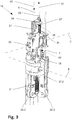
- FIG. 3 shows the in the FIG. 2 illustrated embodiment of the locking device 16 is rotated by 90 ° about the axis A.
- corresponding covers of the locking device 16 are shown in this figure.
- the figure shows the attachment of the actuator 28 with the linearly movable second plate 31.
- the second plate 31 has an angled at 90 ° relative to the rest of the second plate 31 area with an opening 39 through which the actuator formed as a Bowden cable 28th is performed.
- the lower side of the angled region forms a second abutment surface 38, on which a second driver 37 arranged on the actuating device strikes in the first direction 33 during a movement of the actuating device 28.
- the second driver 37 is not fixedly connected to the angled portion of the second plate 31, the actuator 28 is free to move in the second direction 34. As a result, the first plate 18 can be moved further in the second direction than the second plate 31.
- the first plate 18 is also in the same way via a first driver 41 which abuts against a first abutment surface 42 of the first plate 18 when the Actuator 28 is moved in the first direction 33, connected to the actuator 28.
- both plates 18, 31 can be moved freely with the actuating device 28 released by the first coil spring 21 and by the second coil spring 34 in the first position and in the first state.
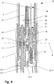
- FIG. 4 shows a section through a length-adjustable leg 15 according to the present invention along the first axis A.
- the sectional plane is in the direction of the second axis B.
- the first pin 17 in the first position, ie it engages positively on a surface of the first boom pin 23.1 a.
- a correspondingly configured surface 22 with positive locking elements At the top of the first pin 17 is a correspondingly configured surface 22 with positive locking elements. As can be seen in this figure, this surface 22 is formed in the embodiment shown on a plug inserted into the first pin 17.
- the overlap of the second telescopic element 3 with the first telescopic element 2, which by the recording of the second Telescopic element 3 is formed in the first telescopic element 3.
- a state is shown with a minimum overlap of the two telescopic elements 2, 3, that is to say the state in which the length-adjustable leg 15 has the greatest length.
- second end of the second telescopic element in turn, three of the four rollers 26.1, 26.2, 26.3 are visible, with which the second telescopic element 3 is mounted linearly displaceable in the first telescopic element 2.
- FIG. 5 is another sectional drawing of the adjustable leg 15 after FIG. 4 shown, but rotated by 90 ° about the first axis A.
- the second pin 30 is disposed within a linear guide 40 which allows the movement of the second pin 30 along the third axis C.
- the second plate 31 consists of three elements, of which two elements 31.1, 31.2 can be seen in the figure.
- the upper element 31.2 is inserted into a holder which is composed of two lower elements 31.1. In the lower elements 31.1 and the second linear guide 32 is introduced, in which the second pin 32 is guided.
- the plain bearing 39 mounted on the inner wall of the first telescopic element 2 can also be seen on this figure.
- the second telescopic element 3 is mounted linearly displaceable within the first telescopic element 2.
Claims (9)
- Meuble, en particulier table, comprenant au moins un pied réglable en longueur (15, 15.1, 15.2), le pied réglable en longueur (15, 15.1, 15.2) comprenant :a) un premier élément télescopique (2, 2.1, 2.2) qui est réalisé sous forme de corps creux,b) un deuxième élément télescopique (3, 3.1, 3.2) supporté de manière déplaçable linéairement le long d'un premier axe (A) à l'intérieur du premier élément télescopique (2, 2.1, 2.2),c) un dispositif de blocage (16) disposé au niveau du deuxième élément télescopique (3, 3.1, 3.2), qui présente au moins une première goupille (17) qui peut être déplacée par le biais d'un dispositif d'actionnement (28) d'une première position dans laquelle l'au moins une première goupille (17) empêche le déplacement du premier élément télescopique (2, 2.1, 2.2) par rapport au deuxième élément télescopique (3, 3.1, 3.2) par engagement par force ou par correspondance de formes, dans une deuxième position dans laquelle le déplacement n'est pas empêché, la première goupille (17) étant supportée dans le dispositif de blocage (16) de telle sorte qu'elle puisse être déplacée le long d'un deuxième axe (B) qui est essentiellement à angle droit par rapport au premier axe (A), et un déplacement du dispositif d'actionnement (28) à l'encontre d'une première force de rappel dans une première direction (41) le long du premier axe, d'une première position verrouillée dans une position déverrouillée, étant converti par le biais d'un premier guide à coulisse (19) en un déplacement de l'au moins une première goupille (17) le long du deuxième axe (B) de la première position à la deuxième position,d) le dispositif de blocage (16) disposant d'au moins une deuxième goupille (30) qui peut être déplacée par le dispositif d'actionnement (28) d'un premier état dans lequel l'au moins une deuxième goupille (30) est pressée contre un côté intérieur d'une paroi du premier élément télescopique (2, 2.1, 2.2) afin de serrer le deuxième élément télescopique (3, 3.1, 3.2) par rapport au premier élément télescopique (2, 2.1, 2.2), et d'un deuxième état dans lequel l'au moins une deuxième goupille (30) est espacée de la paroi du premier élément télescopique (2, 2.1, 2.2),caractérisé en ce que l'au moins une deuxième goupille (17) est supportée dans le dispositif de blocage (16) de telle sorte que celle-ci puisse être déplacée le long d'un troisième axe (C) qui est essentiellement à angle droit par rapport au premier axe (A) et à angle droit par rapport au deuxième axe (B), un déplacement du dispositif d'actionnement (28) à l'encontre d'une deuxième force de rappel qui agit sur l'au moins une deuxième goupille (30), de la position verrouillée dans la position déverrouillée, étant converti par le biais d'un deuxième guide à coulisse (32) en un déplacement de l'au moins une deuxième goupille (30) le long du troisième axe (C) du premier état au deuxième état.
- Meuble selon la revendication 1, caractérisé en ce que le deuxième guide à coulisse (32) est réalisé sous forme de deuxième rainure introduite dans une deuxième plaque (31 ; 31.1, 31.2) déplaçable linéairement le long du premier axe (A), dans laquelle est guidé un deuxième tourillon (33) disposé sur l'au moins une deuxième goupille (30).
- Meuble selon la revendication 2, caractérisé en ce que le deuxième guide à coulisse (32) se présente sous forme de came, la came étant configurée de telle sorte que dans le cas d'un déplacement de l'au moins une deuxième goupille (30) du deuxième état dans le premier état, la came présente d'abord une plus grande pente dans une première région (35) que dans une deuxième région suivante (36) .
- Meuble selon l'une quelconque des revendications 1 à 3, caractérisé en ce que le dispositif d'actionnement (28) dispose d'un deuxième dispositif d'entraînement (37) qui, lors d'un déplacement du dispositif d'actionnement (28) de la position verrouillée dans la position déverrouillée, bute contre une deuxième surface de butée (38) de la deuxième plaque (31, 31.1, 31.2).
- Meuble selon l'une quelconque des revendications 1 à 4, caractérisé en ce que le dispositif de blocage (16) est disposé à l'intérieur du deuxième élément télescopique (3, 3.1, 3.2), au moins une ouverture étant prévue dans une paroi du deuxième élément télescopique (3, 3.1, 3.2), à travers laquelle peut être déplacée l'au moins une deuxième goupille (30).
- Meuble selon l'une quelconque des revendications 1 à 5, caractérisé en ce que le dispositif d'actionnement (28) est réalisé sous forme de câble Bowden.
- Meuble selon l'une quelconque des revendications 1 à 6, caractérisé en ce que dans une région d'une première extrémité de l'au moins un premier élément télescopique (2, 2.1, 2.2) du côté intérieur de la paroi, est disposé au moins un palier lisse (39), qui coopère avec une paroi sur un côté extérieur du deuxième élément télescopique (3, 3.1, 3.2).
- Meuble selon l'une quelconque des revendications 1 à 7, caractérisé en ce que le deuxième élément télescopique (3, 3.1, 3.2) présente au niveau d'une deuxième extrémité au moins un palier à roulement (26.1, 26.2, 26.3, 26.4) qui coopère avec le côté intérieur de la paroi du premier élément télescopique (2, 2.1, 2.2).
- Meuble selon l'une quelconque des revendications 1 à 8, caractérisé en ce qu'à l'intérieur du premier élément télescopique (2, 2.1, 2.2) est disposé au moins un bras de potence (23.1, 23.2) qui s'étend depuis une deuxième extrémité jusqu'à la première extrémité du premier élément télescopique (2, 2.1, 2.2), l'au moins une deuxième goupille (30) coopérant dans le premier état par engagement par force ou par correspondance de formes avec le bras de potence (23.1, 23.2).
Priority Applications (9)
| Application Number | Priority Date | Filing Date | Title |
|---|---|---|---|
| PL13405130T PL2873344T3 (pl) | 2013-11-18 | 2013-11-18 | Mebel z nogą o regulowanej wysokości |
| ES13405130.9T ES2633600T3 (es) | 2013-11-18 | 2013-11-18 | Mueble con pata ajustable en altura |
| EP13405130.9A EP2873344B1 (fr) | 2013-11-18 | 2013-11-18 | Meuble doté d'un pied réglable en hauteur |
| DK13405130.9T DK2873344T3 (en) | 2013-11-18 | 2013-11-18 | Furniture with height adjustable legs |
| AU2014233628A AU2014233628B2 (en) | 2013-11-18 | 2014-09-26 | Furniture item with a vertically adjustable leg |
| US14/542,768 US9380864B2 (en) | 2013-11-18 | 2014-11-17 | Furniture item with a vertically adjustable leg |
| JP2014233546A JP6552807B2 (ja) | 2013-11-18 | 2014-11-18 | 上下調節可能な脚を有する家具 |
| CN201410858312.6A CN104720283B (zh) | 2013-11-18 | 2014-11-18 | 具有可竖直调节的腿的家具制品 |
| HK15108679.4A HK1207947A1 (en) | 2013-11-18 | 2015-09-07 | Furniture item with a vertically adjustable leg |
Applications Claiming Priority (1)
| Application Number | Priority Date | Filing Date | Title |
|---|---|---|---|
| EP13405130.9A EP2873344B1 (fr) | 2013-11-18 | 2013-11-18 | Meuble doté d'un pied réglable en hauteur |
Publications (2)
| Publication Number | Publication Date |
|---|---|
| EP2873344A1 EP2873344A1 (fr) | 2015-05-20 |
| EP2873344B1 true EP2873344B1 (fr) | 2017-04-19 |
Family
ID=49713045
Family Applications (1)
| Application Number | Title | Priority Date | Filing Date |
|---|---|---|---|
| EP13405130.9A Active EP2873344B1 (fr) | 2013-11-18 | 2013-11-18 | Meuble doté d'un pied réglable en hauteur |
Country Status (9)
| Country | Link |
|---|---|
| US (1) | US9380864B2 (fr) |
| EP (1) | EP2873344B1 (fr) |
| JP (1) | JP6552807B2 (fr) |
| CN (1) | CN104720283B (fr) |
| AU (1) | AU2014233628B2 (fr) |
| DK (1) | DK2873344T3 (fr) |
| ES (1) | ES2633600T3 (fr) |
| HK (1) | HK1207947A1 (fr) |
| PL (1) | PL2873344T3 (fr) |
Families Citing this family (17)
| Publication number | Priority date | Publication date | Assignee | Title |
|---|---|---|---|---|
| EP1827170B1 (fr) * | 2004-12-17 | 2016-05-18 | Steelcase Inc. | Table reglable en hauteur |
| WO2013176690A1 (fr) | 2012-05-24 | 2013-11-28 | Gemmy Industries Corporation | Plateforme de bureau réglable |
| US9038549B1 (en) * | 2012-06-01 | 2015-05-26 | Humanscale Corporation | Height adjustable table |
| USD795620S1 (en) * | 2015-01-21 | 2017-08-29 | Stirworks Inc. | Desk with feet |
| USD795619S1 (en) * | 2015-01-21 | 2017-08-29 | Stirworks Inc. | Desk with legs |
| USD807672S1 (en) * | 2015-02-06 | 2018-01-16 | Haworth, Inc. | Support leg |
| CN104983191B (zh) * | 2015-07-27 | 2017-11-21 | 苏州卫生职业技术学院 | 一种可升降式工作台 |
| NL2016762B1 (en) * | 2016-05-12 | 2017-11-27 | Smart Level Table B V | A height adjustable stand and a table comprising the same |
| CN206390562U (zh) | 2016-09-23 | 2017-08-11 | 廖良成 | 电动升降电脑桌及其办公桌 |
| US11019920B2 (en) | 2016-09-23 | 2021-06-01 | Varidesk, Llc | Electrically-lifted computer desk and office desk thereof |
| PL3378350T3 (pl) * | 2017-03-21 | 2021-01-11 | Rol Ergo Ab | Kolumna teleskopowa z kablem wewnętrznym |
| DE102017110247A1 (de) * | 2017-05-11 | 2018-11-15 | Hettich Franke Gmbh & Co. Kg | Schwenkbeschlag und Möbel |
| WO2019174686A2 (fr) | 2018-03-14 | 2019-09-19 | Linak A/S | Cadre pour une table |
| CN108741625A (zh) * | 2018-06-28 | 2018-11-06 | 浙江乐歌智能驱动科技有限公司 | 一种转动助力机构及其应用的升降桌 |
| US11419410B1 (en) * | 2021-02-05 | 2022-08-23 | Shanghai Tengfei Communication Equipment Industry Co., Ltd | Lifting table |
| NL2028871B1 (en) | 2021-07-28 | 2023-02-02 | Smart Level Table B V | A height-adjustable multi-legged stand and an assembly comprising the same |
| US11925154B1 (en) * | 2022-10-11 | 2024-03-12 | CGIP, Inc. | System for plant cultivation |
Family Cites Families (40)
| Publication number | Priority date | Publication date | Assignee | Title |
|---|---|---|---|---|
| US2171653A (en) * | 1938-11-23 | 1939-09-05 | Heitmann Grace | Adjustable column for lamps and other articles |
| US3217672A (en) * | 1964-06-01 | 1965-11-16 | Donald O Haughey | Vertically adjustable table |
| US3323818A (en) * | 1964-11-25 | 1967-06-06 | Gen Motors Corp | Adujustable length mechanism |
| US3999492A (en) * | 1975-06-20 | 1976-12-28 | Emrick, Inc. | Locking device for over-bed table |
| JPS5641546Y2 (fr) * | 1978-05-16 | 1981-09-29 | ||
| JPS5627032U (fr) * | 1979-08-08 | 1981-03-13 | ||
| JPS5948243U (ja) * | 1983-02-21 | 1984-03-30 | コクヨ株式会社 | 製図台などにおける昇降支柱のロツク機構 |
| US4601246A (en) * | 1984-05-07 | 1986-07-22 | Thill, Inc. | Support assembly for overbed table |
| US4607577A (en) * | 1985-08-02 | 1986-08-26 | Leonardo Stephen V | Overbed table |
| DE3634059C2 (de) * | 1986-10-07 | 1996-08-14 | Peter Heckmann | Feststellvorrichtung für ineinander verschiebbare Teleskopbeine höhenverstellbarer Möbel |
| US4850563A (en) * | 1987-06-06 | 1989-07-25 | Ergonomic Equipment Pty. Ltd. | Adjustable desk frame |
| DE4202789C1 (en) * | 1992-01-31 | 1993-05-06 | Josef Attila 7758 Meersburg De Kun | Height-adjustable telescopic leg - has externally released brake between first and second coaxial tubes, incorporating conical sleeves |
| JPH05293016A (ja) * | 1992-04-20 | 1993-11-09 | Matsushita Electric Ind Co Ltd | デスク装置 |
| JP3007296B2 (ja) * | 1996-03-29 | 2000-02-07 | 小泉産業株式会社 | 家具の天板昇降装置 |
| US5706739A (en) | 1996-12-12 | 1998-01-13 | Ergotech (1993) Inc. | Height adjustable counterbalance workstation |
| DE19749494A1 (de) | 1997-11-08 | 1999-05-12 | Rainer Schmidt | Höhenverstellbarer Arbeitstisch |
| US5924658A (en) * | 1998-01-07 | 1999-07-20 | Stryker Corporation | IV pole |
| DE19856864A1 (de) | 1998-12-09 | 2000-06-15 | Wolfgang Blume | Tischgestell mit verstellbarer Höhe |
| US6299113B1 (en) * | 1998-12-18 | 2001-10-09 | Koyo Giken Co., Ltd. | Telescopic member, cylindrical body and molded body |
| EP1050242B1 (fr) * | 1999-05-07 | 2004-06-30 | Konrad Merkt Gmbh | Dispositif de réglage en hauteur pour pièces d'ameublement en particulier pour tables élévatrices |
| US6435112B1 (en) * | 1999-06-04 | 2002-08-20 | Herman Miller, Inc. | Height adjustable table |
| WO2002090819A2 (fr) * | 2001-05-10 | 2002-11-14 | Massachusetts Institute Of Technology | Support d'equipement a pieds multiples pour cameras, telescopes et analogues et blocage par plaque de blocage afferente |
| DE20110101U1 (de) * | 2001-06-19 | 2001-11-15 | Liu Lin Ho | Zusammenschiebbares Gestell |
| US6609686B2 (en) * | 2002-01-18 | 2003-08-26 | Tam Srl | Adjustable support apparatus |
| LU90876B1 (de) | 2002-02-15 | 2003-08-18 | Deceuninck N V | Hoehenverstellbare Stuetzsaeule fuer Unterstuetzung einer Tischplatte |
| FR2844165B1 (fr) * | 2002-09-10 | 2005-09-23 | Atal | Pied reglable notamment pour mobilier de bureau |
| US7104203B2 (en) * | 2004-06-16 | 2006-09-12 | Chiu-Hsiang Lo | Height adjustable device for a retractable tube assembly |
| EP1827170B1 (fr) | 2004-12-17 | 2016-05-18 | Steelcase Inc. | Table reglable en hauteur |
| US8146876B1 (en) * | 2006-02-09 | 2012-04-03 | Primos, Inc. | Telescoping support stand apparatus |
| AU2008226343B2 (en) * | 2007-03-14 | 2013-08-01 | Gesswein, Andreas Klaus | Length adjustable member |
| US20130214111A1 (en) * | 2009-06-05 | 2013-08-22 | William Bishop | Telescopic support with internal brake |
| EP2301382A1 (fr) * | 2009-09-25 | 2011-03-30 | Siemens AB | Colonne télescopique pour le réglage de la hauteur |
| DE102009045707A1 (de) | 2009-10-14 | 2011-04-21 | Veyhl Gmbh | Teleskopierbare Säule |
| US8215241B2 (en) * | 2010-02-25 | 2012-07-10 | Msb Design | Vertical linear actuator mechanism |
| NL2004931C2 (nl) * | 2010-06-21 | 2011-12-22 | Resqtec Zumro B V | Veiligheidsinrichting. |
| CN103037735B (zh) * | 2010-07-29 | 2016-06-01 | 利纳克有限公司 | 优选用于高度可调节桌的升降柱 |
| GB2483876A (en) * | 2010-09-22 | 2012-03-28 | Nicholas David Le Sueur | Seat height adjustment mechanism |
| JP2012161386A (ja) * | 2011-02-04 | 2012-08-30 | Isokawa Sangyo | 昇降装置 |
| DE102011054332B4 (de) | 2011-10-10 | 2014-06-18 | WHN Technologies GmbH | Teleskopierendes Führungssystem |
| US9599137B2 (en) * | 2012-01-06 | 2017-03-21 | MarathonNoroco Aerospace, Inc. | Internal locking mechanism for a hold open rod |
-
2013
- 2013-11-18 EP EP13405130.9A patent/EP2873344B1/fr active Active
- 2013-11-18 PL PL13405130T patent/PL2873344T3/pl unknown
- 2013-11-18 ES ES13405130.9T patent/ES2633600T3/es active Active
- 2013-11-18 DK DK13405130.9T patent/DK2873344T3/en active
-
2014
- 2014-09-26 AU AU2014233628A patent/AU2014233628B2/en active Active
- 2014-11-17 US US14/542,768 patent/US9380864B2/en active Active
- 2014-11-18 JP JP2014233546A patent/JP6552807B2/ja active Active
- 2014-11-18 CN CN201410858312.6A patent/CN104720283B/zh active Active
-
2015
- 2015-09-07 HK HK15108679.4A patent/HK1207947A1/xx unknown
Non-Patent Citations (1)
| Title |
|---|
| None * |
Also Published As
| Publication number | Publication date |
|---|---|
| JP6552807B2 (ja) | 2019-07-31 |
| PL2873344T3 (pl) | 2017-09-29 |
| AU2014233628A1 (en) | 2015-06-04 |
| AU2014233628B2 (en) | 2019-01-24 |
| CN104720283B (zh) | 2020-03-03 |
| ES2633600T3 (es) | 2017-09-22 |
| HK1207947A1 (en) | 2016-02-19 |
| CN104720283A (zh) | 2015-06-24 |
| JP2015119956A (ja) | 2015-07-02 |
| US9380864B2 (en) | 2016-07-05 |
| DK2873344T3 (en) | 2017-07-24 |
| EP2873344A1 (fr) | 2015-05-20 |
| US20150136000A1 (en) | 2015-05-21 |
Similar Documents
| Publication | Publication Date | Title |
|---|---|---|
| EP2873344B1 (fr) | Meuble doté d'un pied réglable en hauteur | |
| EP3311693B1 (fr) | Châssis réglable en hauteur comprenant des éléments de jambage rabattables | |
| EP2146114B1 (fr) | Entraînement à double broche télescopique | |
| EP1987734B1 (fr) | Dispositif de synchronisation de mouvement d'éléments d'appui | |
| DE102014109376B4 (de) | Operationstischfuß für einen Operationstisch | |
| EP2213198B1 (fr) | Assise de meuble | |
| EP1604589B1 (fr) | Dispositif de réglage de la hauteur d'une table | |
| DE3406669A1 (de) | Gewichtsausgleichsvorrichtung fuer hoehenverstellbare moebel mit vorzugsweise nur einem standbein | |
| DE102010060153B3 (de) | Drehwellenanordnung sowie Stützeinrichtung mit einer solchen | |
| DE202010002230U1 (de) | Beschlag für einen Eckschrank und Eckschrank | |
| EP2994021B1 (fr) | Sommier à lattes avec entraînement par moteur électrique | |
| DE102004063580A1 (de) | Möbelstück mit bewegbarem Möbelsegment | |
| DE4039097C2 (de) | Höhenverstellbarer Fuß für Möbel | |
| EP2716180B1 (fr) | Bureau réglable en hauteur, en particulier pour poste de travail avec écran | |
| DE2807941A1 (de) | Aus einem tisch und einem oder mehreren stuehlen bestehender block | |
| CH707352B1 (de) | Teleskopierbarer Spindelantrieb und ein Tischmöbel mit einem teleskopierbaren Spindelantrieb. | |
| DE102016008673B4 (de) | Höhenverstelleinrichtung für ein Möbel | |
| DE19626854B4 (de) | Traggestell für einen höhenverstellbaren Tisch | |
| AT509542A1 (de) | Gelenkbeschlag für sitzmöbel | |
| DE102011076409B4 (de) | Klappbare Säule für ein Möbelstück und Möbelstück mit einer klappbaren Säule | |
| DE102006019624B4 (de) | Höhenverstellbarer Tisch | |
| DE19642592C2 (de) | Höhenverstellbarer Tisch | |
| DE202006017393U1 (de) | Mobile manuell stufenlos höheneinstellbare Präsentationsvorrichtung | |
| DE4446108C1 (de) | Verstelleinrichtung zur Höhenverstellung von Möbeln | |
| WO2016062717A1 (fr) | Meuble combiné |
Legal Events
| Date | Code | Title | Description |
|---|---|---|---|
| PUAI | Public reference made under article 153(3) epc to a published international application that has entered the european phase |
Free format text: ORIGINAL CODE: 0009012 |
|
| 17P | Request for examination filed |
Effective date: 20131118 |
|
| AK | Designated contracting states |
Kind code of ref document: A1 Designated state(s): AL AT BE BG CH CY CZ DE DK EE ES FI FR GB GR HR HU IE IS IT LI LT LU LV MC MK MT NL NO PL PT RO RS SE SI SK SM TR |
|
| AX | Request for extension of the european patent |
Extension state: BA ME |
|
| R17P | Request for examination filed (corrected) |
Effective date: 20150715 |
|
| RBV | Designated contracting states (corrected) |
Designated state(s): AL AT BE BG CH CY CZ DE DK EE ES FI FR GB GR HR HU IE IS IT LI LT LU LV MC MK MT NL NO PL PT RO RS SE SI SK SM TR |
|
| 17Q | First examination report despatched |
Effective date: 20160519 |
|
| RIC1 | Information provided on ipc code assigned before grant |
Ipc: F16B 7/10 20060101ALN20160812BHEP Ipc: A47B 9/20 20060101AFI20160812BHEP Ipc: A47B 9/08 20060101ALI20160812BHEP |
|
| GRAP | Despatch of communication of intention to grant a patent |
Free format text: ORIGINAL CODE: EPIDOSNIGR1 |
|
| STAA | Information on the status of an ep patent application or granted ep patent |
Free format text: STATUS: GRANT OF PATENT IS INTENDED |
|
| INTG | Intention to grant announced |
Effective date: 20161116 |
|
| RIN1 | Information on inventor provided before grant (corrected) |
Inventor name: SCHAERER, ALEXANDER Inventor name: DIENES, THOMAS Inventor name: HOELTSCHI, NIKLAUS |
|
| GRAS | Grant fee paid |
Free format text: ORIGINAL CODE: EPIDOSNIGR3 |
|
| GRAA | (expected) grant |
Free format text: ORIGINAL CODE: 0009210 |
|
| STAA | Information on the status of an ep patent application or granted ep patent |
Free format text: STATUS: THE PATENT HAS BEEN GRANTED |
|
| AK | Designated contracting states |
Kind code of ref document: B1 Designated state(s): AL AT BE BG CH CY CZ DE DK EE ES FI FR GB GR HR HU IE IS IT LI LT LU LV MC MK MT NL NO PL PT RO RS SE SI SK SM TR |
|
| REG | Reference to a national code |
Ref country code: GB Ref legal event code: FG4D Free format text: NOT ENGLISH |
|
| REG | Reference to a national code |
Ref country code: CH Ref legal event code: EP |
|
| REG | Reference to a national code |
Ref country code: AT Ref legal event code: REF Ref document number: 885073 Country of ref document: AT Kind code of ref document: T Effective date: 20170515 |
|
| REG | Reference to a national code |
Ref country code: IE Ref legal event code: FG4D Free format text: LANGUAGE OF EP DOCUMENT: GERMAN |
|
| REG | Reference to a national code |
Ref country code: DE Ref legal event code: R096 Ref document number: 502013007010 Country of ref document: DE |
|
| REG | Reference to a national code |
Ref country code: CH Ref legal event code: NV Representative=s name: KELLER AND PARTNER PATENTANWAELTE AG, CH |
|
| REG | Reference to a national code |
Ref country code: DK Ref legal event code: T3 Effective date: 20170719 |
|
| REG | Reference to a national code |
Ref country code: NL Ref legal event code: FP |
|
| REG | Reference to a national code |
Ref country code: LT Ref legal event code: MG4D |
|
| REG | Reference to a national code |
Ref country code: ES Ref legal event code: FG2A Ref document number: 2633600 Country of ref document: ES Kind code of ref document: T3 Effective date: 20170922 |
|
| REG | Reference to a national code |
Ref country code: FR Ref legal event code: PLFP Year of fee payment: 5 |
|
| PG25 | Lapsed in a contracting state [announced via postgrant information from national office to epo] |
Ref country code: LT Free format text: LAPSE BECAUSE OF FAILURE TO SUBMIT A TRANSLATION OF THE DESCRIPTION OR TO PAY THE FEE WITHIN THE PRESCRIBED TIME-LIMIT Effective date: 20170419 Ref country code: HR Free format text: LAPSE BECAUSE OF FAILURE TO SUBMIT A TRANSLATION OF THE DESCRIPTION OR TO PAY THE FEE WITHIN THE PRESCRIBED TIME-LIMIT Effective date: 20170419 Ref country code: GR Free format text: LAPSE BECAUSE OF FAILURE TO SUBMIT A TRANSLATION OF THE DESCRIPTION OR TO PAY THE FEE WITHIN THE PRESCRIBED TIME-LIMIT Effective date: 20170720 Ref country code: FI Free format text: LAPSE BECAUSE OF FAILURE TO SUBMIT A TRANSLATION OF THE DESCRIPTION OR TO PAY THE FEE WITHIN THE PRESCRIBED TIME-LIMIT Effective date: 20170419 Ref country code: NO Free format text: LAPSE BECAUSE OF FAILURE TO SUBMIT A TRANSLATION OF THE DESCRIPTION OR TO PAY THE FEE WITHIN THE PRESCRIBED TIME-LIMIT Effective date: 20170719 |
|
| PG25 | Lapsed in a contracting state [announced via postgrant information from national office to epo] |
Ref country code: SE Free format text: LAPSE BECAUSE OF FAILURE TO SUBMIT A TRANSLATION OF THE DESCRIPTION OR TO PAY THE FEE WITHIN THE PRESCRIBED TIME-LIMIT Effective date: 20170419 Ref country code: RS Free format text: LAPSE BECAUSE OF FAILURE TO SUBMIT A TRANSLATION OF THE DESCRIPTION OR TO PAY THE FEE WITHIN THE PRESCRIBED TIME-LIMIT Effective date: 20170419 Ref country code: BG Free format text: LAPSE BECAUSE OF FAILURE TO SUBMIT A TRANSLATION OF THE DESCRIPTION OR TO PAY THE FEE WITHIN THE PRESCRIBED TIME-LIMIT Effective date: 20170719 Ref country code: LV Free format text: LAPSE BECAUSE OF FAILURE TO SUBMIT A TRANSLATION OF THE DESCRIPTION OR TO PAY THE FEE WITHIN THE PRESCRIBED TIME-LIMIT Effective date: 20170419 Ref country code: IS Free format text: LAPSE BECAUSE OF FAILURE TO SUBMIT A TRANSLATION OF THE DESCRIPTION OR TO PAY THE FEE WITHIN THE PRESCRIBED TIME-LIMIT Effective date: 20170819 |
|
| REG | Reference to a national code |
Ref country code: DE Ref legal event code: R097 Ref document number: 502013007010 Country of ref document: DE |
|
| PG25 | Lapsed in a contracting state [announced via postgrant information from national office to epo] |
Ref country code: CZ Free format text: LAPSE BECAUSE OF FAILURE TO SUBMIT A TRANSLATION OF THE DESCRIPTION OR TO PAY THE FEE WITHIN THE PRESCRIBED TIME-LIMIT Effective date: 20170419 Ref country code: EE Free format text: LAPSE BECAUSE OF FAILURE TO SUBMIT A TRANSLATION OF THE DESCRIPTION OR TO PAY THE FEE WITHIN THE PRESCRIBED TIME-LIMIT Effective date: 20170419 Ref country code: SK Free format text: LAPSE BECAUSE OF FAILURE TO SUBMIT A TRANSLATION OF THE DESCRIPTION OR TO PAY THE FEE WITHIN THE PRESCRIBED TIME-LIMIT Effective date: 20170419 Ref country code: RO Free format text: LAPSE BECAUSE OF FAILURE TO SUBMIT A TRANSLATION OF THE DESCRIPTION OR TO PAY THE FEE WITHIN THE PRESCRIBED TIME-LIMIT Effective date: 20170419 |
|
| PLBE | No opposition filed within time limit |
Free format text: ORIGINAL CODE: 0009261 |
|
| STAA | Information on the status of an ep patent application or granted ep patent |
Free format text: STATUS: NO OPPOSITION FILED WITHIN TIME LIMIT |
|
| PG25 | Lapsed in a contracting state [announced via postgrant information from national office to epo] |
Ref country code: SM Free format text: LAPSE BECAUSE OF FAILURE TO SUBMIT A TRANSLATION OF THE DESCRIPTION OR TO PAY THE FEE WITHIN THE PRESCRIBED TIME-LIMIT Effective date: 20170419 |
|
| 26N | No opposition filed |
Effective date: 20180122 |
|
| PG25 | Lapsed in a contracting state [announced via postgrant information from national office to epo] |
Ref country code: SI Free format text: LAPSE BECAUSE OF FAILURE TO SUBMIT A TRANSLATION OF THE DESCRIPTION OR TO PAY THE FEE WITHIN THE PRESCRIBED TIME-LIMIT Effective date: 20170419 |
|
| PG25 | Lapsed in a contracting state [announced via postgrant information from national office to epo] |
Ref country code: MC Free format text: LAPSE BECAUSE OF FAILURE TO SUBMIT A TRANSLATION OF THE DESCRIPTION OR TO PAY THE FEE WITHIN THE PRESCRIBED TIME-LIMIT Effective date: 20170419 |
|
| PG25 | Lapsed in a contracting state [announced via postgrant information from national office to epo] |
Ref country code: MT Free format text: LAPSE BECAUSE OF FAILURE TO SUBMIT A TRANSLATION OF THE DESCRIPTION OR TO PAY THE FEE WITHIN THE PRESCRIBED TIME-LIMIT Effective date: 20170419 |
|
| REG | Reference to a national code |
Ref country code: FR Ref legal event code: PLFP Year of fee payment: 6 |
|
| PG25 | Lapsed in a contracting state [announced via postgrant information from national office to epo] |
Ref country code: HU Free format text: LAPSE BECAUSE OF FAILURE TO SUBMIT A TRANSLATION OF THE DESCRIPTION OR TO PAY THE FEE WITHIN THE PRESCRIBED TIME-LIMIT; INVALID AB INITIO Effective date: 20131118 |
|
| PG25 | Lapsed in a contracting state [announced via postgrant information from national office to epo] |
Ref country code: CY Free format text: LAPSE BECAUSE OF FAILURE TO SUBMIT A TRANSLATION OF THE DESCRIPTION OR TO PAY THE FEE WITHIN THE PRESCRIBED TIME-LIMIT Effective date: 20170419 |
|
| PG25 | Lapsed in a contracting state [announced via postgrant information from national office to epo] |
Ref country code: MK Free format text: LAPSE BECAUSE OF FAILURE TO SUBMIT A TRANSLATION OF THE DESCRIPTION OR TO PAY THE FEE WITHIN THE PRESCRIBED TIME-LIMIT Effective date: 20170419 |
|
| PG25 | Lapsed in a contracting state [announced via postgrant information from national office to epo] |
Ref country code: TR Free format text: LAPSE BECAUSE OF FAILURE TO SUBMIT A TRANSLATION OF THE DESCRIPTION OR TO PAY THE FEE WITHIN THE PRESCRIBED TIME-LIMIT Effective date: 20170419 |
|
| PG25 | Lapsed in a contracting state [announced via postgrant information from national office to epo] |
Ref country code: PT Free format text: LAPSE BECAUSE OF FAILURE TO SUBMIT A TRANSLATION OF THE DESCRIPTION OR TO PAY THE FEE WITHIN THE PRESCRIBED TIME-LIMIT Effective date: 20170419 |
|
| PG25 | Lapsed in a contracting state [announced via postgrant information from national office to epo] |
Ref country code: AL Free format text: LAPSE BECAUSE OF FAILURE TO SUBMIT A TRANSLATION OF THE DESCRIPTION OR TO PAY THE FEE WITHIN THE PRESCRIBED TIME-LIMIT Effective date: 20170419 |
|
| REG | Reference to a national code |
Ref country code: CH Ref legal event code: PFA Owner name: USM HOLDING AG, CH Free format text: FORMER OWNER: USM HOLDING AG, CH |
|
| REG | Reference to a national code |
Ref country code: DE Ref legal event code: R082 Ref document number: 502013007010 Country of ref document: DE Representative=s name: SPLANEMANN PATENTANWAELTE PARTNERSCHAFT MBB, DE Ref country code: DE Ref legal event code: R081 Ref document number: 502013007010 Country of ref document: DE Owner name: USM U. SCHAERER SOEHNE AG, CH Free format text: FORMER OWNER: USM HOLDING AG, MURI, CH |
|
| REG | Reference to a national code |
Ref country code: BE Ref legal event code: PD Owner name: USM U. SCHAERER SOEHNE AG; CH Free format text: DETAILS ASSIGNMENT: CHANGE OF OWNER(S), FUSION; FORMER OWNER NAME: USM HOLDING AG Effective date: 20200918 |
|
| REG | Reference to a national code |
Ref country code: NL Ref legal event code: PD Owner name: USM U. SCHAERER SOEHNE AG; CH Free format text: DETAILS ASSIGNMENT: CHANGE OF OWNER(S), MERGE; FORMER OWNER NAME: USM HOLDING AG Effective date: 20201029 |
|
| REG | Reference to a national code |
Ref country code: LU Ref legal event code: PD Owner name: USM U. SCHAERER SOEHNE AG; CH Effective date: 20201109 |
|
| REG | Reference to a national code |
Ref country code: ES Ref legal event code: PC2A Owner name: USM U. SCHAERER SOEHNE AG Effective date: 20210216 |
|
| REG | Reference to a national code |
Ref country code: GB Ref legal event code: 732E Free format text: REGISTERED BETWEEN 20210204 AND 20210210 |
|
| REG | Reference to a national code |
Ref country code: AT Ref legal event code: PC Ref document number: 885073 Country of ref document: AT Kind code of ref document: T Owner name: USM U. SCHAERER SOEHNE AG, CH Effective date: 20211011 |
|
| PGFP | Annual fee paid to national office [announced via postgrant information from national office to epo] |
Ref country code: ES Payment date: 20221201 Year of fee payment: 10 |
|
| PGFP | Annual fee paid to national office [announced via postgrant information from national office to epo] |
Ref country code: PL Payment date: 20221020 Year of fee payment: 10 Ref country code: BE Payment date: 20221130 Year of fee payment: 10 |
|
| PGFP | Annual fee paid to national office [announced via postgrant information from national office to epo] |
Ref country code: NL Payment date: 20231120 Year of fee payment: 11 Ref country code: LU Payment date: 20231120 Year of fee payment: 11 |
|
| PGFP | Annual fee paid to national office [announced via postgrant information from national office to epo] |
Ref country code: GB Payment date: 20231123 Year of fee payment: 11 |
|
| PGFP | Annual fee paid to national office [announced via postgrant information from national office to epo] |
Ref country code: IT Payment date: 20231124 Year of fee payment: 11 Ref country code: IE Payment date: 20231121 Year of fee payment: 11 Ref country code: FR Payment date: 20231120 Year of fee payment: 11 Ref country code: DK Payment date: 20231124 Year of fee payment: 11 Ref country code: DE Payment date: 20231025 Year of fee payment: 11 Ref country code: CH Payment date: 20231201 Year of fee payment: 11 Ref country code: AT Payment date: 20231121 Year of fee payment: 11 |
|
| PGFP | Annual fee paid to national office [announced via postgrant information from national office to epo] |
Ref country code: PL Payment date: 20231113 Year of fee payment: 11 Ref country code: BE Payment date: 20231120 Year of fee payment: 11 |
|
| PGFP | Annual fee paid to national office [announced via postgrant information from national office to epo] |
Ref country code: ES Payment date: 20240129 Year of fee payment: 11 |