EP2146114B1 - Entraînement à double broche télescopique - Google Patents
Entraînement à double broche télescopique Download PDFInfo
- Publication number
- EP2146114B1 EP2146114B1 EP09009298.2A EP09009298A EP2146114B1 EP 2146114 B1 EP2146114 B1 EP 2146114B1 EP 09009298 A EP09009298 A EP 09009298A EP 2146114 B1 EP2146114 B1 EP 2146114B1
- Authority
- EP
- European Patent Office
- Prior art keywords
- thread
- spindle
- coupling element
- linear drive
- nut
- Prior art date
- Legal status (The legal status is an assumption and is not a legal conclusion. Google has not performed a legal analysis and makes no representation as to the accuracy of the status listed.)
- Not-in-force
Links
Images


Classifications
-
- F—MECHANICAL ENGINEERING; LIGHTING; HEATING; WEAPONS; BLASTING
- F16—ENGINEERING ELEMENTS AND UNITS; GENERAL MEASURES FOR PRODUCING AND MAINTAINING EFFECTIVE FUNCTIONING OF MACHINES OR INSTALLATIONS; THERMAL INSULATION IN GENERAL
- F16H—GEARING
- F16H25/00—Gearings comprising primarily only cams, cam-followers and screw-and-nut mechanisms
- F16H25/18—Gearings comprising primarily only cams, cam-followers and screw-and-nut mechanisms for conveying or interconverting oscillating or reciprocating motions
- F16H25/20—Screw mechanisms
- F16H25/2056—Telescopic screws with at least three screw members in coaxial arrangement
-
- Y—GENERAL TAGGING OF NEW TECHNOLOGICAL DEVELOPMENTS; GENERAL TAGGING OF CROSS-SECTIONAL TECHNOLOGIES SPANNING OVER SEVERAL SECTIONS OF THE IPC; TECHNICAL SUBJECTS COVERED BY FORMER USPC CROSS-REFERENCE ART COLLECTIONS [XRACs] AND DIGESTS
- Y10—TECHNICAL SUBJECTS COVERED BY FORMER USPC
- Y10T—TECHNICAL SUBJECTS COVERED BY FORMER US CLASSIFICATION
- Y10T74/00—Machine element or mechanism
- Y10T74/18—Mechanical movements
- Y10T74/18568—Reciprocating or oscillating to or from alternating rotary
- Y10T74/18576—Reciprocating or oscillating to or from alternating rotary including screw and nut
- Y10T74/18664—Shaft moves through rotary drive means
-
- Y—GENERAL TAGGING OF NEW TECHNOLOGICAL DEVELOPMENTS; GENERAL TAGGING OF CROSS-SECTIONAL TECHNOLOGIES SPANNING OVER SEVERAL SECTIONS OF THE IPC; TECHNICAL SUBJECTS COVERED BY FORMER USPC CROSS-REFERENCE ART COLLECTIONS [XRACs] AND DIGESTS
- Y10—TECHNICAL SUBJECTS COVERED BY FORMER USPC
- Y10T—TECHNICAL SUBJECTS COVERED BY FORMER US CLASSIFICATION
- Y10T74/00—Machine element or mechanism
- Y10T74/18—Mechanical movements
- Y10T74/18568—Reciprocating or oscillating to or from alternating rotary
- Y10T74/18576—Reciprocating or oscillating to or from alternating rotary including screw and nut
- Y10T74/18672—Plural screws in series [e.g., telescoping, etc.]
-
- Y—GENERAL TAGGING OF NEW TECHNOLOGICAL DEVELOPMENTS; GENERAL TAGGING OF CROSS-SECTIONAL TECHNOLOGIES SPANNING OVER SEVERAL SECTIONS OF THE IPC; TECHNICAL SUBJECTS COVERED BY FORMER USPC CROSS-REFERENCE ART COLLECTIONS [XRACs] AND DIGESTS
- Y10—TECHNICAL SUBJECTS COVERED BY FORMER USPC
- Y10T—TECHNICAL SUBJECTS COVERED BY FORMER US CLASSIFICATION
- Y10T74/00—Machine element or mechanism
- Y10T74/18—Mechanical movements
- Y10T74/18568—Reciprocating or oscillating to or from alternating rotary
- Y10T74/18576—Reciprocating or oscillating to or from alternating rotary including screw and nut
- Y10T74/18688—Limit stop
Definitions
- the invention relates to a linear drive, in particular a spindle drive according to the preamble of claim 1. Furthermore, the invention relates to an adjusting unit with a linear drive according to claim 8.
- the two substantially extending over the height of the lifting device in its retracted position threaded spindles are arranged directly one inside the other, the threaded spindles by a tongue and groove or a Mehrkantring Insert axially movable (slidably) and rotatably connected to each other.
- the lifting device is relatively complex and requires many components.
- the drive is exclusively via the first threaded spindle.
- a linear actuator having a first member and a second member provided with internal threads cut in opposite directions and an intermediate member engaging and axially displaceable with the first and second via external threads complementary to the threads are provided on the first and the second member.
- the linear actuator further comprises a sheath extending over the intermediate member, the sheath being rotatable with respect to the first and second members but slidable longitudinally.
- the linear drive also includes a drive rod which is rotatable but longitudinally displaceable within the intermediate member.
- a medical delivery device which is provided with such a linear actuator is also provided.
- a telescopically movable structure comprising a nut which is rotatably mounted with respect to a frame member, a spindle tube having a nut engaging with the external thread, wherein the spindle tube further has an internal thread having a direction opposite to the external thread, wherein the internal thread with a externally threaded non-rotatable spindle is engaged, wherein the spindle tube rotatably, but axially displaceably connected to a drive shaft, wherein the drive shaft has a substantially polygonal cross-section, wherein a periphery forms two opposite longitudinal tracks for engagement with torque-transmitting rolling elements, which are mounted in a sleeve mounted in the spindle tube, thereby enabling the transmission of a large torque without the risk of seizing between the drive shaft and the spindle tube.
- the hollow spindle is internally formed as a driver profile, wherein between hollow spindle and inner spindle with a Mit fortuneprofil provided, driven by an electric motor driving profile tube is arranged, whose profile corresponds to that of the hollow spindle and wherein the hollow spindle is slidable on the driving profile tube, wherein the outer nut sits on the hollow spindle, which is connected via a pipe fixed to the motor housing, wherein by the Mit Cyprus profile tube driven hollow spindle out of the connected to the connecting tube outer nut or can screw in, the arranged on the front of the hollow spindle nut engages in the inner spindle, the inner spindle at its front Eren end is rotationally fixed to the secondary part of the fitting to be adjusted and is thus
- an exhibition display case comprising: a base for a bell, a bell adapted to define, together with the base, a display space with respect to an external environment, and an opening device for the showcase which forms an opening by vertical displacement of the bell realized with respect to the base, wherein the opening device comprises at least two lifting groups, each of which comprises at least three coaxial telescopic elements, which are actuated by a worm mechanism. It is therefore an object of the present invention to provide a linear drive and furniture with linear drive, in which a simpler structure, in particular with fewer components, is realized.
- the invention includes the technical teaching that in a linear drive, in particular a spindle drive, arranged with a centrally between a first element and a second element, rotatably driven coupling element, coupled to the coupling element in operative connection, in particular rotation-resistant, first element and a coupled to the coupling element in operative connection, the first element axially opposite, in particular fixed, second element, so that the two opposing elements move apart via the movable coupling element, that is to say longitudinally displace in the axial direction, wherein a coupling of the elements with the coupling element via corresponding thread pairings, it is provided that the thread pairings are formed as opposite thread pairings to provide a compact, substantially three-piece linear drive with a maximum travel, said first element as a first threaded spindle with a first spindle thread, the second element is designed as a second threaded spindle with a second spindle thread and the coupling element as a spindle nut with one corresponding to each spindle thread, cooperating
- the invention also includes the technical teaching that in a linear drive, namely a spindle drive, arranged with a centrally disposed between a first element and a second element, rotatably driven coupling element, coupled to the coupling element in operative connection, the first element and with the coupling element coupled in operative connection, the first element axially opposite, second element, so that the two opposing elements apart via the movable coupling element move, that is, in the axial direction to move longitudinally, with a coupling of the elements with the coupling element via corresponding thread pairings, the thread pairings are designed as opposite thread pairings to provide a compact, substantially three-piece linear drive with a maximum travel is provided in that the first element is designed as a first spindle nut with a first female thread, the second element as a second spindle nut with a second female thread and the coupling element as a double threaded spindle with one spindle thread corresponding to each female thread cooperating with the corresponding female thread, wherein the Double-thre
- the invention also includes the technical teaching that in a linear drive, namely a spindle drive, arranged with a centrally disposed between a first element and a second element, rotatably driven coupling element, coupled to the coupling element in operative connection, the first element and with the coupling element operatively coupled, the the first element disposed axially opposite, the second element, so that the two opposing elements move apart on the movable coupling element, that move longitudinally in the axial direction, with a coupling of the elements with the coupling element via corresponding thread pairings, wherein the thread pairings as opposing thread pairings are formed to provide a compact, substantially three-piece linear drive with a maximum travel, wherein the first element as a first threaded spindle with a first spindle thread, the second element as a second spindle nut with a second female thread and the coupling element as a threaded nut Spindle having a first female thread, which cooperates with the first spindle thread, and a second spind
- the linear drive can be formed as a telescopic linear drive, that is, the two opposing fixed elements can be moved apart via the movable coupling element, that move longitudinally in the axial direction.
- a synchronous extension that is, axial movement relative to the coupling element, the elements realized via a drive.
- the elements can be designed as hollow elements or as solid elements.
- the first element as a first threaded spindle with a first spindle thread
- the second Element as a second threaded spindle with a second spindle thread
- the coupling element is designed as a spindle nut with one corresponding to each screw thread, cooperating with the corresponding spindle thread nut thread, wherein a first thread pair comprising the first spindle thread and a corresponding first nut thread in opposite directions to a second thread pairing comprising the second spindle thread and a corresponding second nut thread is formed.
- first element as a first spindle nut with a first female thread
- second element as a second spindle nut with a second female thread
- the coupling element as a threaded spindle with one corresponding to each female thread
- a first thread pair comprising the first nut thread and a corresponding first spindle thread is formed in opposite directions to a second thread pairing comprising the second nut thread and a corresponding second spindle thread.
- the threaded spindle has two different threads.
- the threads can be formed one behind the other on a same surface. Alternatively, the threads may be formed on different surfaces. Also, the threads can be formed superimposed on the same surface.
- the threaded spindle may preferably be formed as a double-threaded spindle.
- the first element as a first threaded spindle with a first spindle thread
- the second element as a second spindle nut with a second female thread
- the coupling element as a threaded nut spindle with a first female thread, which cooperates with the first spindle thread
- a second spindle thread which cooperates with the second nut thread
- Yet another embodiment of the present invention provides that the second element as a first threaded spindle with a first screw thread, the first element as a second spindle nut with a second female thread and the coupling element as a threaded nut spindle with a first female thread, which cooperates with the first spindle thread, and a second spindle thread, which cooperates with the second female thread, is formed, wherein a first thread pairing comprising the first nut thread and a corresponding first screw thread opposite to a second thread pairing comprising the second nut thread and a corresponding second spindle thread is formed ,
- This embodiment represents the inverse of the embodiment immediately above.
- the two elements are aligned coaxially with each other.
- the elements can also be formed offset from each other, it is preferred for a simple structure that the elements are arranged coaxially to one another.
- At least one of the two elements is designed as a hollow element with a hollow interior, in which the other element is at least partially retractable.
- a maximum Ausfahrweg can be realized with a minimum space requirement.
- the invention provides that the threads have substantially the same thread pitch with opposite spindle pairing thread direction, so that a synchronous operation, that is, a synchronous extension is feasible.
- the elements are axially moved substantially equally, that is approximately in the ratio 1: 1.
- At least one of the elements has a stop for limiting a linear movement of the linear drive.
- the stop can be designed to be displaceable or fixed.
- a suitable material for the stop is, for example, an elastic material such as rubber, hard rubber and the like.
- a solid material such as steel, metal or the like may be selected as the material for the stop.
- the stop is designed as a ring, in particular as a snap ring or Segering.
- the stop can act in particular in a movable, that is not stationary, arrangement for adjusting the linear drive.
- a control can be adjusted via the stop, for example during a first operation or during a readjustment.
- the stop can be used as an installation and / or installation aid.
- the stop can be arranged at any position on one of the elements, for example at one end adjacent to the coupling element or at the end remote from the coupling element.
- the linear drive has at least one guide device for guiding at least one of the elements.
- the guide can be used in particular elongated elements which are exposed to buckling without guide device.
- the guide device can further improve the running property of the linear drive.
- the guide device may for example be formed as a profile tube, for example as a profile tube with non-rotationally symmetrical cross section.
- the guide device in particular in the form of a profile tube with non-rotationally symmetrical cross section can be used as rotation. The rotation ensures that the corresponding element does not rotate with the coupling element.
- the linear drive can be rotatably mounted on an element with another component such as a piece of furniture or the like.
- the other element may be secured against rotation with the coupling element via the guide device.
- This is particularly advantageous when the linear drive is used in a table leg, in particular in rotationally symmetrical table legs.
- the then upstanding on the floor element can rotate in case of insufficient contact force without guide device in an adjustment on the ground, so that sanding marks.
- the guide device may be formed as a support sleeve, which can accommodate, for example, axial forces. No axial forces act on the guide device.
- a further embodiment of the present invention provides that the guide device is integrally formed on at least one of the elements.
- the linear drive further has a compact design with few components.
- the guide means can be moved together.
- the guide device is designed to be telescopic.
- the installation height of the linear drive is solely dependent on the design of the two elements and the coupling element. A possible actuator height does not flow into the installation height of the linear drive if it is designed accordingly.
- At least one guide device is formed as a separate component in the coupling element.
- the Guide device can be the Guide device also form on the coupling element. As a result, a guide of the coupling element is ensured.
- the coupling element has two axially spaced coupling regions each having a corresponding thread, wherein the threads are formed axially aligned and correspond to the respective thread of the elements.
- the spaced-apart coupling regions are preferably spaced such that this distance substantially corresponds to the length of one of the elements.
- Yet another embodiment of the present invention provides that the distance of the coupling regions is formed corresponding to at least one of the lengths of the threads of the elements, so that at least one of the threads of the elements is substantially retractable into a cavity defined between the coupling regions and a coupling wall. In this way, a compact linear drive can be realized in the contracted state.
- the distance is formed substantially corresponding to an axial length of the hollow interior.
- the coupling element has at least one driving device arranged on a wall side facing away from the cavity.
- the coupling element can be coupled with a part to be moved, for example, a table leg or the like, so that, for example, a stroke adjustment is possible.
- the linear drive is essentially formed in three parts with a coupling element and two elements. If the linear drive integrated in a table leg or the like, the table leg is accordingly also form three parts.
- a middle part is then coupled via the driver to, in a height adjustment of the table leg, the middle part or the middle parts in a predetermined relative position to the other two To position parts of the table leg.
- the middle part is coupled to the coupling element such that the middle part is always arranged centrally to the other two adjacent parts of the table leg.
- an actuator device is provided with an actuator for driving the coupling element. While the elements are fixed, the coupling element can be rotated via the actuator, whereby an axial movement of the spindles is realized. The fact that only one element, namely the coupling element, is driven, a synchronous moving apart of the spindles in the axial direction can be realized. About the thread pitch can be, for example, a Ausfahrssel the spindles or more generally the elements set.
- the actuator or the actuator device can be arranged directly on the coupling element. Preferably, the actuator is arranged at one end of the linear drive, so that it can be arranged concealed in an installation on adjusting such as tables.
- the coupling element is designed so that neither the motor nor the coupling part must absorb substantially axial forces of the (linear drive or) the driving load, and is thus decoupled via the coupling part of the linear drive with respect to axial forces.
- the actuator device can be designed such that its overall height has no influence on the overall height of the linear drive.
- the actuator may have a corresponding passage through which the linear drive can be at least partially inserted, in particular an element of the linear drive.
- the actuator surrounds the linear drive.
- the coupling part can also be arranged, so that this also has no effect on the installation height of the actuator.
- the coupling element can be driven by hand, for example via a crank or another tool.
- Preferably designed as an electric motor or the like actuator is provided.
- the actuator device comprises a coupling part for coupling the actuator to the actuator Having coupling element.
- the coupling element is driven by the actuator, that is moved.
- the coupling part and the coupling element each have corresponding engaging means for transmitting a driving force from the actuator to the coupling element.
- the actuator device is decoupled from the linear drive with respect to axial forces of the linear drive.
- the coupling part may, for example, like the coupling element, also be formed as a square tube.
- Another embodiment of the present invention provides that the engagement means have an anti-rotation, in particular respectively corresponding, non-rotationally symmetrical contours. In this way, a torsion-proof power transmission can take place by nesting of coupling element and coupling part.
- the coupling part is formed as a profile tube with a hollow interior for at least partially receiving one of the elements. In this way, an extremely compact design of the linear drive can be realized by parts are arranged in the interior.
- the inner space has a length that corresponds essentially to a length of the receiving thread of the element.
- the coupling part can be arranged on the inside, that is, it runs at least partially in a cavity in the elements and / or the coupling element.
- the invention further includes the technical teaching that, in an adjusting unit, comprising at least a first and a second adjusting part, which are adjustable relative to one another, a linear drive according to the invention for adjusting the adjusting unit and / or the adjusting units connected thereto is provided.
- the adjustment unit may be a furniture unit, an automotive unit, a lamp unit, a monitor unit or any other unit in which at least two components are moved axially controlled with respect to each other
- the first and / or the second adjustment part has / have an adjustment part cavity in which the linear drive is at least partially arranged.
- the coupling element and the elements are to be arranged in the adjustment part cavity.
- Yet another embodiment of the present invention provides that the first, the second or any adjustment part is adjustably coupled via a driving of the linear drive with the linear drive / are. Due to the compact design, the linear drive can be easily arranged in the adjustment unit.
- the adjustment is designed as a piece of furniture, selected from the group comprising: table legs, chair legs, legs, bed legs, Bettenverstell Roaden, computer tables and the like.
- the linear drive is constructed in the simplest case of three components: a first element, a second element and in between with a coupling element which couples the two elements.
- the rotation can be done by an actuator.
- the actuator device is decoupled in terms of axial forces of the three components listed above.
- the elements are arranged against rotation. This can be done for example via a separate anti-rotation, which is realized for example by a guide device.
- the linear actuator with actuator device and optionally with guide device requires no axial bearing to accommodate axial loads.
- the suspension of the linear drive can take place by means of the guide device, which is designed to prevent rotation, on one side, so that an element is suspended rotationally fixed.
- the actuator device is controlled by a controller. This can be adjusted with respect to predeterminable extension position, for example using a stop. This can be easily adjusted, for example, starting and ending position.
- the linear drive is designed as a telescopic drive. The three components, which can be formed substantially the same length, can be moved into each other, so that there is a compact design in the retracted state, which corresponds approximately to the length of a component. The achievable with this linear drive maximum stroke then corresponds to about twice the length of the linear drive in the retracted state. With a corresponding thread design (counter-rotating, thread pitch equal), a synchronous method of the linear drive can be realized.
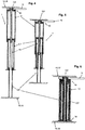
- the linear drive 1 is designed as a telescopic double spindle drive with a central, drivable coupling element 2, a coupled to the coupling element 2 in operative connection, non-driven, that is fixed with respect to a rotation, first element 3rd and a fixed to the coupling element 2 in Wirkver Struktur, the first element 3 arranged axially opposite, fixed second element 4.
- the first element 3 is formed as a first threaded spindle 5 with a first screw thread 5a.
- the second element 4 is formed as a second threaded spindle 6 with a second spindle thread 6a.
- the second threaded spindle 6 and also the coupling element 2 are presently designed as hollow components, once as a hollow spindle and once as a hollow tube, with a hollow interior 9, in which the first threaded spindle 5 is at least partially retractable.
- the second element 4 is substantially formed as a hollow cylinder.
- the coupling element 2, the first element 3 and the second element 4 are arranged coaxially with each other, so that they give a telescopic structure.
- the coupling element 2 is formed as a spindle nut 7 with a first female thread 7a, which corresponds to the first element 3, more precisely the first spindle thread 5a, and a second female thread 8a, which corresponds to the second spindle thread 6a.
- the two female threads 7a, 8a are axially spaced from each other, wherein the distance substantially corresponds to the length of the threads 5a, 6a of the threaded spindles 5.6 in the longitudinal direction.
- the linear drive 1 comprises an actuator device 10, which comprises an actuator 11 and a coupling part 12.
- the actuator 11 is designed as an (electric) motor which drives the coupling part 12.
- the coupling part 12 is formed as a hollow profile tube, which is engaged via engagement means 13 with the coupling element 2.
- the engagement means 13 are formed as non-rotationally symmetrical contours.
- the coupling part 12 is formed as a hollow profile drive tube, which the coupling element 2 at least partially against rotation includes, wherein the outer contour of the coupling element 2 is not rotationally symmetrical, as well as the inner contour of the drive tube (corresponding coupling part 12).
- the profile drive tube is designed as a square tube.
- the first threaded spindle 5 is arranged, and partially the coupling element 2.
- the drive tube 12 is also arranged coaxially with the coupling element 2 and the two threaded spindles 3 and 4.
- a three-part linear drive 1 is formed with actuator 10. Special bearings or bearing elements, in particular axial bearings for absorbing axial forces, are not required for the mounting of the elements 3, 4.
- the linear drive 1 is shown substantially in a maximum extension length.
- the second threaded spindle 6 has at its end located in the coupling element 2 a stop 2a which abuts against a corresponding section of the coupling element 2 from the inside when an adjustable maximum extension distance is reached.
- FIG. 2 is the linear actuator 1 after Fig. 1 only partially retracted or extended.
- the components of the linear drive 1, the coupling element 2 and the two elements 3, 4 are driven into one another, so that only a minimum installation space for the linear drive 1 is required.
- the coupling element 2 and the second threaded spindle 6 are retracted into the drive tube 12.
- the linear drive 1 In the longitudinal direction, ie in the axial direction, the length of the linear drive 1 is approximately equal to the axial length of the first threaded spindle 5.
- the linear drive 1 more precisely, the coupling element 2 at the remote to the actuator 11 located at the end of a drive 14, via which an adjustment with the linear drive 1 can be coupled.
- the thread pairings are between first threaded spindle 5 and coupling element 2, and second nut thread 8 and second element 4, more precisely, the second spindle thread 6a and the coupling element 2, more precisely formed the female thread 8a in opposite directions. That is, in the present case, the first threaded spindle 5 has a right-hand thread and the second threaded spindle 6 has a left-hand thread or vice versa.
- a hatched area is shown at the top and bottom of the linear drives 1, respectively.
- This area represents, for example, components that are adjustable relative to each other via the linear drive 1, in particular in the axial direction of the linear drive 1.
- the hatched area indicates that the actuator is fixed relative to the hatched area.
- the hatched area represents an adjustment unit 16, which comprises a first adjustment part 17 and a second adjustment part 18, which are adjustable relative to one another, in particular in the axial direction.
- the adjustment unit 16 is coupled via the driver 14 with the linear drive 1 and can be adjusted accordingly. Is a non-rotating guide device 15 ( Fig4-6 ), so the linear drive must not be rotationally fixed with respect to the hatched area 18, since the guide means 15 prevents co-rotation with the coupling element 2.
- Figures 4-6 show the linear drive 1 with an additional support and guide sleeve 15.
- the linear actuator 1 corresponds to Fig. 4-6 to the linear drive Fig. 1-3
- the support guide sleeve 15 is preferably arranged in the coupling element 2 and causes easier threading of the first threaded spindle 5 in the second threaded spindle 6 when retracting the linear drive 1.
- the support guide sleeve 15 is cylindrical, so that it saves space in the linear drive. 1 can be arranged.
- FIGS. 7 to 9 show another embodiment of the linear actuator 1, wherein the coupling element 2 and the elements 3,4 with respect to their execution Fig. 1-3 differ.
- the coupling element 2 is in the Fig. 7-9 designed as a drivable threaded spindle 5, more precisely as a double-threaded spindle 5.
- Die Double-threaded spindle 5 is formed in a circumferentially outer region as a hollow spindle. In an inner region located therein, the double-threaded spindle 5 can be formed as a full-threaded spindle or as a hollow threaded spindle.
- the threaded spindle 5 in the inner region formed as a hollow spindle to receive the coupling member 12 of the actuator 10 operatively connected therein.
- the threaded spindle 5 has a first spindle thread 5a, which is designed as an external thread.
- the threaded spindle 5 in the inner region, a second spindle thread 6a, which is also designed as an external thread, but in opposite directions to the other external thread.
- the threaded spindle 5 points in the Fig. 7-9 So two threaded spindle sections, which are multi-part, preferably formed in one piece.
- the elements 3, 4 are in the Fig. 7-9 formed as a spindle nuts 7.8, more precisely as fixed tailpipes, in particular as a round or profile tubes with corresponding female thread sections, which cooperate with the corresponding, corresponding thread of the coupling element 2.
- first element 3 which essentially form the linear drive 1
- second element 4 which essentially form the linear drive 1
- the first element 3 is designed as a first threaded spindle 5, in particular as a hollow spindle.
- the coupling element 2 is formed as a second threaded spindle 6, wherein it is formed in an outer region as a hollow spindle and in an inner region as a profile tube or as a profiled bar, each with a corresponding thread.
- the second element 4 is formed as a spindle nut 7, which has a corresponding female thread 7a on a region located to the coupling element 2.
Claims (11)
- Entraînement linéaire (1), en particulier entraînement à broche, muni d'un élément d'accouplement (2) qui est disposé au milieu entre un premier élément (3) et un deuxième élément (4) et qui peut être entraîné en rotation, du premier élément (3) qui est couplé en liaison opérationnelle à l'élément d'accouplement (2), et du deuxième élément (4) qui est couplé en liaison opérationnelle à l'élément d'accouplement (2) et qui est disposé axialement à l'opposé du premier élément (3) de sorte que les deux éléments (3, 4) opposés peuvent être écartés l'un de l'autre par l'intermédiaire de l'élément d'accouplement (2) mobile, c'est-à-dire qu'ils peuvent être déplacés longitudinalement en direction axiale, les éléments (3, 4) étant couplés à l'élément d'accouplement (2) par le biais de paires de filetages correspondants, caractérisé en ce que les paires de filetages sont réalisées sous la forme de paires de filetages à rotation opposée pour former un entraînement linéaire (1) compact, essentiellement en trois parties ayant une course de déplacement maximale, le premier élément (3) étant réalisé sous la forme d'une première broche filetée (5) avec un premier filetage de broche (5a), le deuxième élément (4) étant réalisé sous la forme d'une deuxième broche filetée (6) avec un deuxième filetage de broche (6a), et l'élément d'accouplement (2) étant réalisé sous la forme d'un écrou de broche (7) avec, pour chaque filetage de broche (5a, 6a), un filetage d'écrou (7a, 8a) correspondant coopérant avec le filetage de broche (5a, 6a) correspondant, une première paire de filetages (5a, 7a), comprenant le premier filetage de broche (5a) et un premier filetage d'écrou (7a) correspondant, étant réalisée avec un sens de rotation inversé à une seconde paire de filetages (6a, 8a) comprenant le deuxième filetage de broche (6a) et un deuxième filetage d'écrou (8a) correspondant, et l'élément d'accouplement (2) ayant deux zones d'accouplement espacées axialement l'une de l'autre et présentant chacune un filetage correspondant qui correspond au filetage respectif des éléments (3, 4), les filetages étant alignés axialement et l'élément d'accouplement (2) comprenant au moins un dispositif d'entraînement (14) par l'intermédiaire duquel une unité de réglage peut être couplée à l'entraînement linéaire (1), le dispositif d'entraînement (14) étant disposé sur un côté de paroi de l'élément d'accouplement (2) opposé à une cavité dans l'élément d'accouplement (2).
- Entraînement linéaire (1), à savoir un entraînement à broche, muni d'un élément d'accouplement (2) qui est disposé au milieu entre un premier élément (3) et un deuxième élément (4) et qui peut être entraîné en rotation, du premier élément (3) qui est couplé en liaison opérationnelle à l'élément d'accouplement (2), et du deuxième élément (4) qui est couplé en liaison opérationnelle à l'élément d'accouplement (2) et qui est disposé axialement à l'opposé du premier élément (3) de sorte que les deux éléments (3, 4) opposés peuvent être écartés l'un de l'autre par l'intermédiaire de l'élément d'accouplement (2) mobile, c'est-à-dire qu'ils peuvent être déplacés longitudinalement en direction axiale, les éléments (3, 4) étant couplés à l'élément d'accouplement (2) par le biais de paires de filetages correspondants, les paires de filetages étant réalisées sous la forme de paires de filetages à rotation opposée pour former un entraînement linéaire (1) compact, essentiellement en trois parties ayant une course de déplacement maximale, caractérisé en ce que le premier élément (3) est réalisé sous la forme d'un premier écrou de broche (7) avec un premier filetage d'écrou (7a), le deuxième élément (4) est réalisé sous la forme d'un deuxième écrou de broche (8) avec un deuxième filetage d'écrou (8a), et l'élément de couplage (2) est réalisé sous la forme d'une broche à double filetage (5) avec un filetage de broche (5a, 6a) correspondant à chaque filetage d'écrou (7a, 8a) et coopérant avec le filetage d'écrou (7a, 8a) correspondant, la broche à double filetage (5) étant réalisée sous la forme d'une broche creuse dans une région externe circonférentielle et pouvant être réalisée, dans une région interne se trouve à l'intérieure, sous la forme d'une broche à filetage pleine ou d'une broche à filetage creuse, une première paire de filetages (5a, 7a), comprenant le premier filetage d'écrou (7a) et un premier filetage de broche (5a) correspondant, étant réalisée avec un sens de rotation inversé à une deuxième paire de filetages (8a, 6a) comprenant le deuxième filetage d'écrou (8a) et un deuxième filetage de broche (6a) correspondant, et les filetages (5a, 6a, 7a, 8a) présentant le même pas de filetage avec un sens de filetage des paires de broches (5a-7a, 6a-8a) inversé, l'élément d'accouplement (2) ayant deux zones d'accouplement espacées axialement l'une de l'autre et présentant chacune un filetage correspondant qui correspond au filetage respectif des éléments (3, 4), les filetages étant alignés axialement, un dispositif d'entraînement (14) étant disposé sur un côté de paroi de l'élément d'accouplement (2) opposé à une cavité dans l'élément d'accouplement (2), et/ou l'élément d'accouplement (2) comprenant au moins un dispositif d'entraînement (14) par l'intermédiaire duquel une unité de réglage peut être couplée à l'entraînement linéaire (1), le dispositif d'entraînement (14) étant disposé sur un côté de paroi de l'élément d'accouplement (2) opposé à une cavité dans l'élément d'accouplement (2).
- Entraînement linéaire (1), à savoir un entraînement à broche, muni d'un élément d'accouplement (2) qui est disposé au milieu entre un premier élément (3) et un deuxième élément (4) et qui peut être entraîné en rotation, du premier élément (3) qui est couplé en liaison opérationnelle à l'élément d'accouplement (2), et du deuxième élément (4) qui est couplé en liaison opérationnelle à l'élément d'accouplement (2) et qui est disposé axialement à l'opposé du premier élément (3) de sorte que les deux éléments (3, 4) opposés peuvent être écartées l'un de l'autre par l'intermédiaire de l'élément d'accouplement (2) mobile, c'est-à-dire qu'ils peuvent être déplacés longitudinalement en direction axiale, les éléments (3, 4) étant couplés à l'élément d'accouplement (2) par le biais de paires de filetages correspondantes, les paires de filetages étant réalisées sous la forme de paires de filetages à sens de rotation inversé pour former un entraînement linéaire (1) compact, essentiellement en trois parties ayant une course de déplacement maximale, le premier élément (3) étant réalisé sous la forme d'une première broche filetée (5) avec un premier filetage de broche (5a), le deuxième élément (4) sous la forme d'un deuxième écrou de broche (8) avec un deuxième filetage d'écrou (8a) et l'élément d'accouplement (2) sous la forme d'une broche-écrou filetée avec un premier filetage d'écrou (7a) coopérant avec le premier filetage de broche (5a) et un deuxième filetage de broche (6a) coopérant avec le deuxième filetage d'écrou (8a), une première paire de filetages (5a, 7a), comprenant le premier filetage d'écrou (7a) et un premier filetage de broche (5a) correspondant, étant réalisée avec un sens de rotation inversé à une deuxième paire de filetages (8a, 6a) comprenant le deuxième filetage d'écrou (8a) et un deuxième filetage de broche (6a) correspondant, les filetages (5a, 6a, 7a, 8a) présentant sensiblement le même pas de filetage avec un sens de filetage des paires de broches (5a-7a, 6a-8a) inversé, caractérisé en ce que l'élément d'accouplement (2) comprend au moins un dispositif d'entraînement (14) par l'intermédiaire duquel une unité de réglage peut être couplée à l'entraînement linéaire (1), le dispositif d'entraînement (14) étant disposé sur un côté de paroi de l'élément d'accouplement (2) opposé à une cavité de l'élément d'accouplement (2).
- Entraînement linéaire (1) selon l'une des revendications précédentes 1 à 3, caractérisé en ce qu'au moins l'un des deux éléments (3, 4) est réalisé sous la forme d'un élément creux avec un espace intérieur creux (9) dans lequel l'autre élément (4, 3) peut être au moins partiellement rentré.
- Entraînement linéaire (1) selon l'une des revendications précédentes 1 à 4, caractérisé en ce que l'entraînement linéaire (1) est muni d'au moins un dispositif de guidage (15) pour guider au moins l'un des éléments (3, 4).
- Entraînement linéaire (1) selon l'une des revendications précédentes 1 à 5, caractérisé en ce que la distance entre les zones d'accouplement est réalisée pour correspondre à au moins une des longueurs des filetages des éléments (3, 4), de sorte qu'au moins un des filetages des éléments (3, 4) peut être rentré essentiellement dans une cavité définie entre les zones d'accouplement et une paroi d'accouplement.
- Entraînement linéaire (1) selon l'une des revendications précédentes 1 à 6, caractérisé en ce qu'un dispositif d'actionnement (10) avec un actionneur (11) est en outre prévu pour entraîner l'élément de couplage (2).
- Unité de réglage (16) comprenant au moins une première et une deuxième partie de réglage (17, 18) pouvant être réglées l'une par rapport à l'autre, avec un entraînement linéaire (1) selon l'une des revendications précédentes 1 à 7 pour régler l'unité de réglage (16) et/ou les unités de réglage reliées à celui-ci.
- Unité de réglage (16) selon la revendication 8, caractérisée en ce que la première et/ou la deuxième partie de réglage (17, 18) présente(nt) une cavité de pièce de réglage dans laquelle l'entraînement linéaire (1) est disposé au moins en partie.
- Unité de réglage (16) selon la revendication 8 ou 9, caractérisée en ce que la première et/ou la deuxième partie de réglage (17, 18) est/sont couplée(s) de manière réglable à l'entraînement linéaire (1) par l'intermédiaire d'un entraînement (14) de l'entraînement linéaire (1).
- Unité de réglage (16) selon l'une des revendications précédentes 8 à 10, caractérisée en ce que l'unité de réglage (16) est conçue comme un meuble choisi dans le groupe comprenant : des pieds de table, des pieds de chaise, des pieds d'étagère, des pieds de lit, des dispositifs de réglage de lit, des tables d'ordinateurs, et autres éléments comparables.
Applications Claiming Priority (1)
| Application Number | Priority Date | Filing Date | Title |
|---|---|---|---|
| DE102008033887A DE102008033887B4 (de) | 2008-07-18 | 2008-07-18 | Teleskop-Doppelspindelantrieb |
Publications (3)
| Publication Number | Publication Date |
|---|---|
| EP2146114A2 EP2146114A2 (fr) | 2010-01-20 |
| EP2146114A3 EP2146114A3 (fr) | 2011-08-17 |
| EP2146114B1 true EP2146114B1 (fr) | 2019-10-16 |
Family
ID=41258118
Family Applications (1)
| Application Number | Title | Priority Date | Filing Date |
|---|---|---|---|
| EP09009298.2A Not-in-force EP2146114B1 (fr) | 2008-07-18 | 2009-07-16 | Entraînement à double broche télescopique |
Country Status (5)
| Country | Link |
|---|---|
| US (1) | US8601889B2 (fr) |
| EP (1) | EP2146114B1 (fr) |
| DE (1) | DE102008033887B4 (fr) |
| DK (1) | DK2146114T3 (fr) |
| HU (1) | HUE048587T2 (fr) |
Families Citing this family (30)
| Publication number | Priority date | Publication date | Assignee | Title |
|---|---|---|---|---|
| US9656019B2 (en) | 2007-10-02 | 2017-05-23 | Medimop Medical Projects Ltd. | Apparatuses for securing components of a drug delivery system during transport and methods of using same |
| WO2009044401A2 (fr) | 2007-10-02 | 2009-04-09 | Yossi Gross | Pompe à médicament externe |
| KR101075319B1 (ko) * | 2008-05-21 | 2011-10-19 | 삼성에스디아이 주식회사 | 리튬이온 이차전지용 전해액 및 이를 포함하는 리튬이온이차전지 |
| CN102278439A (zh) * | 2010-06-08 | 2011-12-14 | 朱豪东 | 一种伸缩式机械结构 |
| US9764464B2 (en) * | 2011-08-03 | 2017-09-19 | The Boeing Company | Robot including telescopic assemblies for positioning an end effector |
| US20150075306A1 (en) * | 2012-03-08 | 2015-03-19 | Thomson Industries, Inc. | Telescoping linear actuator with screw drives |
| DE102012102298B4 (de) * | 2012-03-19 | 2015-10-29 | Logicdata Electronic & Software Entwicklungs Gmbh | Linearaktuator und höhenverstellbarer Tisch |
| DE102012013979A1 (de) * | 2012-07-13 | 2014-01-16 | Logicdata Electronic & Software Entwicklungs Gmbh | Linaearaktuator und Verfahren zum Herstellen eines Linearaktuators |
| TWM459317U (zh) * | 2013-03-28 | 2013-08-11 | Timotion Technology Co Ltd | 具雙螺桿之線性傳動裝置 |
| WO2015085243A1 (fr) * | 2013-12-05 | 2015-06-11 | Innovative Office Products, Llc | Appareil de support multi-affichage extensible |
| WO2015172962A1 (fr) * | 2014-05-14 | 2015-11-19 | Meamedical Ag | Dispositif de dosage pour l'administration d'un fluide médicamenteux depuis un réservoir, comprenant une tige à broche destinée à la translation du piston |
| WO2015172828A1 (fr) * | 2014-05-14 | 2015-11-19 | Meamedical Ag | Dispositif à broche pour un piston d'un réservoir contenant un fluide médicamenteux |
| US10576207B2 (en) | 2015-10-09 | 2020-03-03 | West Pharma. Services IL, Ltd. | Angled syringe patch injector |
| US9987432B2 (en) | 2015-09-22 | 2018-06-05 | West Pharma. Services IL, Ltd. | Rotation resistant friction adapter for plunger driver of drug delivery device |
| CN113648488B (zh) | 2015-10-09 | 2024-03-29 | 西医药服务以色列分公司 | 至预填充的流体储存器的弯曲流体路径附加装置 |
| CN105534096A (zh) * | 2015-12-14 | 2016-05-04 | 无锡市永亿精密铸造有限公司 | 一种伸缩式耐用型柜腿 |
| EP3405227B1 (fr) | 2016-01-21 | 2020-06-17 | West Pharma. Services Il, Ltd. | Confinement de force dans un injecteur automatique |
| WO2017127215A1 (fr) | 2016-01-21 | 2017-07-27 | Medimop Medical Projects Ltd. | Mécanisme d'introduction et de rétraction d'aiguille |
| CN113041432B (zh) | 2016-01-21 | 2023-04-07 | 西医药服务以色列有限公司 | 包括视觉指示物的药剂输送装置 |
| US11389597B2 (en) * | 2016-03-16 | 2022-07-19 | West Pharma. Services IL, Ltd. | Staged telescopic screw assembly having different visual indicators |
| CN109562229B (zh) | 2016-08-01 | 2021-07-13 | 西医药服务以色列有限公司 | 抗旋转药筒销 |
| EP3315154B1 (fr) | 2016-10-28 | 2021-07-07 | maxon international ag | Entraînement de broche télescopique biétagé |
| CN106641148B (zh) * | 2017-01-10 | 2020-09-18 | 浙江捷昌线性驱动科技股份有限公司 | 一种传动总成及升降立柱 |
| EP3630226A1 (fr) | 2017-05-30 | 2020-04-08 | West Pharma. Services Il, Ltd. | Train d'entraînement modulaire pour injecteur pouvant être porté |
| EP3480000B1 (fr) * | 2017-11-03 | 2020-12-30 | CL Schutzrechtsverwaltungs GmbH | Module d'alimentation |
| CN114144603A (zh) * | 2019-06-04 | 2022-03-04 | 孩之宝公司 | 伸缩件及其机构 |
| DE102020113960A1 (de) | 2020-05-25 | 2021-11-25 | Brose Fahrzeugteile Se & Co. Kommanditgesellschaft, Bamberg | Spindelantrieb zur motorischen Verstellung eines Verstellelements eines Kraftfahrzeugs |
| US11624429B1 (en) | 2021-07-28 | 2023-04-11 | The United States Of America As Represented By The Secretary Of The Navy | Compact linear drive mechanism |
| CN113561857A (zh) * | 2021-08-05 | 2021-10-29 | 诺创汽车科技(上海)有限公司 | 推进机构和车辆座椅 |
| DE102022105754A1 (de) * | 2022-03-11 | 2023-09-14 | Brand Gmbh + Co Kg | Pipettiervorrichtung |
Family Cites Families (12)
| Publication number | Priority date | Publication date | Assignee | Title |
|---|---|---|---|---|
| US1532702A (en) * | 1924-11-10 | 1925-04-07 | Lane Brothers Company | Lifting jack |
| DE2920133C2 (de) | 1979-05-18 | 1981-11-12 | Alfred 4072 Wickrath Bautz | Hubvorrichtung mit mindestens zwei gegeneinander teleskopartig ausfahrbaren Gewindespindeln |
| DE3910814A1 (de) * | 1989-04-04 | 1990-10-11 | Hasenclever Maschf Sms | Schraubgetriebene linearhubeinheit |
| DE10018742B4 (de) * | 2000-04-15 | 2004-09-16 | OKIN Gesellschaft für Antriebstechnik mbH & Co. KG | Vorrichtung zum Verstellen von relativ zueinander beweglichen Teilen |
| EP1286909B1 (fr) * | 2000-05-22 | 2005-04-27 | Ideassociates (IOM) Limited | Structure telescopique |
| DE20108882U1 (de) * | 2001-05-28 | 2002-10-10 | Flamme Klaus Peter | Doppelspindelmotor |
| US6786890B2 (en) * | 2002-01-25 | 2004-09-07 | Novo Nordisk A/S | Linear actuator and a medical delivery device comprising such linear actuator |
| EP1510157A1 (fr) * | 2003-09-01 | 2005-03-02 | Goppion S.r.l. | Vitrine comportant un mécanisme d'ouverture perfectionné |
| US7185868B2 (en) * | 2005-01-05 | 2007-03-06 | Gemmy Industries Corporation | Telescopic display stand |
| US7712389B2 (en) * | 2006-05-16 | 2010-05-11 | T-Motion Technology Co., Ltd. | Lifting device having parallel double screw rods |
| US20080028878A1 (en) * | 2006-08-07 | 2008-02-07 | Chia-Jung Wang | Lifting Device having Double Screw Rods |
| US7752932B2 (en) * | 2008-04-06 | 2010-07-13 | Hiwin Mikrosystem Corp. | Linear actuator |
-
2008
- 2008-07-18 DE DE102008033887A patent/DE102008033887B4/de not_active Expired - Fee Related
-
2009
- 2009-07-16 HU HUE09009298A patent/HUE048587T2/hu unknown
- 2009-07-16 DK DK09009298.2T patent/DK2146114T3/da active
- 2009-07-16 EP EP09009298.2A patent/EP2146114B1/fr not_active Not-in-force
- 2009-07-17 US US12/505,248 patent/US8601889B2/en active Active
Non-Patent Citations (1)
| Title |
|---|
| None * |
Also Published As
| Publication number | Publication date |
|---|---|
| DE102008033887A1 (de) | 2010-01-28 |
| EP2146114A2 (fr) | 2010-01-20 |
| US8601889B2 (en) | 2013-12-10 |
| EP2146114A3 (fr) | 2011-08-17 |
| DK2146114T3 (da) | 2020-01-20 |
| HUE048587T2 (hu) | 2020-08-28 |
| US20100018334A1 (en) | 2010-01-28 |
| DE102008033887B4 (de) | 2012-02-09 |
Similar Documents
| Publication | Publication Date | Title |
|---|---|---|
| EP2146114B1 (fr) | Entraînement à double broche télescopique | |
| EP3341262B1 (fr) | Colonne de direction réglable conçue pour un véhicule automobile | |
| DE60110412T2 (de) | Teleskopische struktur | |
| EP3829956B1 (fr) | Mécanisme de réglage destiné à une colonne de direction et colonne de direction pour véhicule automobile | |
| EP2873344B1 (fr) | Meuble doté d'un pied réglable en hauteur | |
| EP3817963B1 (fr) | Colonne de direction pour un véhicule automobile | |
| EP3274611B1 (fr) | Actionneur télescopique à quatre éléments, pourvu d'un entraînement par filetage | |
| DE102012102298B4 (de) | Linearaktuator und höhenverstellbarer Tisch | |
| DE102018119426B4 (de) | Verstellbare Hubsäule und verstellbares Tischsystem | |
| DE102010000970B4 (de) | Höhenverstellbare Betätigungs-Einrichtung | |
| EP2777136B1 (fr) | Actionnement linéaire pour des meubles | |
| DE202005002585U1 (de) | Elektromotorischer Linearantrieb | |
| EP2594157A2 (fr) | Colonne élévatrice télescopique d'une partie de meuble | |
| WO1996005991A1 (fr) | Commande d'arbre a plusieurs etages destinee a convertir un mouvement rotatif en mouvement lineaire | |
| EP3011864A1 (fr) | Procede de reglage en hauteur d'un premier element par rapport a un second element, complement d'equipement pour un tel dispositif et systeme reglable en hauteur comprenant plusieurs dispositifs dudit type | |
| WO2019174883A1 (fr) | Articulation de bras pour un manipulateur et manipulateur | |
| EP2886506B1 (fr) | Colonne de levage | |
| DE102014210253B4 (de) | Getriebe für eine in einer Höhe verstellbare Ablage sowie Verfahren zum Verändern einer Höhe einer Ablage | |
| DE202006008307U1 (de) | Hubvorrichtung mit Gewindestangen | |
| DE102007039823B4 (de) | Antriebseinrichtung | |
| EP1710202A2 (fr) | Dispositif de levage | |
| DE3129101A1 (de) | Laengenveraenderbare vorrichtung zum verstellen der position eines fahrzeugsitzes | |
| DE102011081340B3 (de) | Stützvorrichtung für einen Sattelanhänger, umfassend einen Spindelmechanismus mit mehrteiliger Spindel, sowie Sattelanhänger mit einer solchen Stützvorrichtung und einer Spindel zur Verwendung in einer Stützvorrichtung | |
| DE102012024805B4 (de) | Teleskopierbarer Spindelantrieb und Tischmöbel mit einem teleskopierbaren Spindelantrieb | |
| DE19920672B4 (de) | Lineare Stellvorrichtung |
Legal Events
| Date | Code | Title | Description |
|---|---|---|---|
| PUAI | Public reference made under article 153(3) epc to a published international application that has entered the european phase |
Free format text: ORIGINAL CODE: 0009012 |
|
| AK | Designated contracting states |
Kind code of ref document: A2 Designated state(s): AT BE BG CH CY CZ DE DK EE ES FI FR GB GR HR HU IE IS IT LI LT LU LV MC MK MT NL NO PL PT RO SE SI SK SM TR |
|
| AX | Request for extension of the european patent |
Extension state: AL BA RS |
|
| PUAL | Search report despatched |
Free format text: ORIGINAL CODE: 0009013 |
|
| AK | Designated contracting states |
Kind code of ref document: A3 Designated state(s): AT BE BG CH CY CZ DE DK EE ES FI FR GB GR HR HU IE IS IT LI LT LU LV MC MK MT NL NO PL PT RO SE SI SK SM TR |
|
| AX | Request for extension of the european patent |
Extension state: AL BA RS |
|
| RIC1 | Information provided on ipc code assigned before grant |
Ipc: F16H 25/20 20060101AFI20110711BHEP |
|
| 17P | Request for examination filed |
Effective date: 20120213 |
|
| 17Q | First examination report despatched |
Effective date: 20120320 |
|
| STAA | Information on the status of an ep patent application or granted ep patent |
Free format text: STATUS: EXAMINATION IS IN PROGRESS |
|
| GRAP | Despatch of communication of intention to grant a patent |
Free format text: ORIGINAL CODE: EPIDOSNIGR1 |
|
| STAA | Information on the status of an ep patent application or granted ep patent |
Free format text: STATUS: GRANT OF PATENT IS INTENDED |
|
| INTG | Intention to grant announced |
Effective date: 20190531 |
|
| GRAS | Grant fee paid |
Free format text: ORIGINAL CODE: EPIDOSNIGR3 |
|
| GRAA | (expected) grant |
Free format text: ORIGINAL CODE: 0009210 |
|
| STAA | Information on the status of an ep patent application or granted ep patent |
Free format text: STATUS: THE PATENT HAS BEEN GRANTED |
|
| AK | Designated contracting states |
Kind code of ref document: B1 Designated state(s): AT BE BG CH CY CZ DE DK EE ES FI FR GB GR HR HU IE IS IT LI LT LU LV MC MK MT NL NO PL PT RO SE SI SK SM TR |
|
| REG | Reference to a national code |
Ref country code: GB Ref legal event code: FG4D Free format text: NOT ENGLISH |
|
| REG | Reference to a national code |
Ref country code: CH Ref legal event code: EP |
|
| REG | Reference to a national code |
Ref country code: DE Ref legal event code: R096 Ref document number: 502009015986 Country of ref document: DE |
|
| REG | Reference to a national code |
Ref country code: IE Ref legal event code: FG4D Free format text: LANGUAGE OF EP DOCUMENT: GERMAN |
|
| REG | Reference to a national code |
Ref country code: AT Ref legal event code: REF Ref document number: 1191593 Country of ref document: AT Kind code of ref document: T Effective date: 20191115 |
|
| REG | Reference to a national code |
Ref country code: DK Ref legal event code: T3 Effective date: 20200114 |
|
| REG | Reference to a national code |
Ref country code: SE Ref legal event code: TRGR |
|
| REG | Reference to a national code |
Ref country code: NL Ref legal event code: MP Effective date: 20191016 |
|
| REG | Reference to a national code |
Ref country code: LT Ref legal event code: MG4D |
|
| REG | Reference to a national code |
Ref country code: SK Ref legal event code: T3 Ref document number: E 33176 Country of ref document: SK |
|
| PG25 | Lapsed in a contracting state [announced via postgrant information from national office to epo] |
Ref country code: LT Free format text: LAPSE BECAUSE OF FAILURE TO SUBMIT A TRANSLATION OF THE DESCRIPTION OR TO PAY THE FEE WITHIN THE PRESCRIBED TIME-LIMIT Effective date: 20191016 Ref country code: PL Free format text: LAPSE BECAUSE OF FAILURE TO SUBMIT A TRANSLATION OF THE DESCRIPTION OR TO PAY THE FEE WITHIN THE PRESCRIBED TIME-LIMIT Effective date: 20191016 Ref country code: GR Free format text: LAPSE BECAUSE OF FAILURE TO SUBMIT A TRANSLATION OF THE DESCRIPTION OR TO PAY THE FEE WITHIN THE PRESCRIBED TIME-LIMIT Effective date: 20200117 Ref country code: NO Free format text: LAPSE BECAUSE OF FAILURE TO SUBMIT A TRANSLATION OF THE DESCRIPTION OR TO PAY THE FEE WITHIN THE PRESCRIBED TIME-LIMIT Effective date: 20200116 Ref country code: ES Free format text: LAPSE BECAUSE OF FAILURE TO SUBMIT A TRANSLATION OF THE DESCRIPTION OR TO PAY THE FEE WITHIN THE PRESCRIBED TIME-LIMIT Effective date: 20191016 Ref country code: NL Free format text: LAPSE BECAUSE OF FAILURE TO SUBMIT A TRANSLATION OF THE DESCRIPTION OR TO PAY THE FEE WITHIN THE PRESCRIBED TIME-LIMIT Effective date: 20191016 Ref country code: LV Free format text: LAPSE BECAUSE OF FAILURE TO SUBMIT A TRANSLATION OF THE DESCRIPTION OR TO PAY THE FEE WITHIN THE PRESCRIBED TIME-LIMIT Effective date: 20191016 Ref country code: BG Free format text: LAPSE BECAUSE OF FAILURE TO SUBMIT A TRANSLATION OF THE DESCRIPTION OR TO PAY THE FEE WITHIN THE PRESCRIBED TIME-LIMIT Effective date: 20200116 Ref country code: PT Free format text: LAPSE BECAUSE OF FAILURE TO SUBMIT A TRANSLATION OF THE DESCRIPTION OR TO PAY THE FEE WITHIN THE PRESCRIBED TIME-LIMIT Effective date: 20200217 Ref country code: FI Free format text: LAPSE BECAUSE OF FAILURE TO SUBMIT A TRANSLATION OF THE DESCRIPTION OR TO PAY THE FEE WITHIN THE PRESCRIBED TIME-LIMIT Effective date: 20191016 |
|
| PG25 | Lapsed in a contracting state [announced via postgrant information from national office to epo] |
Ref country code: IS Free format text: LAPSE BECAUSE OF FAILURE TO SUBMIT A TRANSLATION OF THE DESCRIPTION OR TO PAY THE FEE WITHIN THE PRESCRIBED TIME-LIMIT Effective date: 20200224 Ref country code: HR Free format text: LAPSE BECAUSE OF FAILURE TO SUBMIT A TRANSLATION OF THE DESCRIPTION OR TO PAY THE FEE WITHIN THE PRESCRIBED TIME-LIMIT Effective date: 20191016 |
|
| REG | Reference to a national code |
Ref country code: DE Ref legal event code: R097 Ref document number: 502009015986 Country of ref document: DE |
|
| PG2D | Information on lapse in contracting state deleted |
Ref country code: IS |
|
| PG25 | Lapsed in a contracting state [announced via postgrant information from national office to epo] |
Ref country code: EE Free format text: LAPSE BECAUSE OF FAILURE TO SUBMIT A TRANSLATION OF THE DESCRIPTION OR TO PAY THE FEE WITHIN THE PRESCRIBED TIME-LIMIT Effective date: 20191016 Ref country code: RO Free format text: LAPSE BECAUSE OF FAILURE TO SUBMIT A TRANSLATION OF THE DESCRIPTION OR TO PAY THE FEE WITHIN THE PRESCRIBED TIME-LIMIT Effective date: 20191016 Ref country code: CZ Free format text: LAPSE BECAUSE OF FAILURE TO SUBMIT A TRANSLATION OF THE DESCRIPTION OR TO PAY THE FEE WITHIN THE PRESCRIBED TIME-LIMIT Effective date: 20191016 Ref country code: IS Free format text: LAPSE BECAUSE OF FAILURE TO SUBMIT A TRANSLATION OF THE DESCRIPTION OR TO PAY THE FEE WITHIN THE PRESCRIBED TIME-LIMIT Effective date: 20200216 |
|
| PLBE | No opposition filed within time limit |
Free format text: ORIGINAL CODE: 0009261 |
|
| STAA | Information on the status of an ep patent application or granted ep patent |
Free format text: STATUS: NO OPPOSITION FILED WITHIN TIME LIMIT |
|
| REG | Reference to a national code |
Ref country code: HU Ref legal event code: AG4A Ref document number: E048587 Country of ref document: HU |
|
| PG25 | Lapsed in a contracting state [announced via postgrant information from national office to epo] |
Ref country code: IT Free format text: LAPSE BECAUSE OF FAILURE TO SUBMIT A TRANSLATION OF THE DESCRIPTION OR TO PAY THE FEE WITHIN THE PRESCRIBED TIME-LIMIT Effective date: 20191016 Ref country code: SM Free format text: LAPSE BECAUSE OF FAILURE TO SUBMIT A TRANSLATION OF THE DESCRIPTION OR TO PAY THE FEE WITHIN THE PRESCRIBED TIME-LIMIT Effective date: 20191016 |
|
| 26N | No opposition filed |
Effective date: 20200717 |
|
| PG25 | Lapsed in a contracting state [announced via postgrant information from national office to epo] |
Ref country code: SI Free format text: LAPSE BECAUSE OF FAILURE TO SUBMIT A TRANSLATION OF THE DESCRIPTION OR TO PAY THE FEE WITHIN THE PRESCRIBED TIME-LIMIT Effective date: 20191016 |
|
| PG25 | Lapsed in a contracting state [announced via postgrant information from national office to epo] |
Ref country code: MC Free format text: LAPSE BECAUSE OF FAILURE TO SUBMIT A TRANSLATION OF THE DESCRIPTION OR TO PAY THE FEE WITHIN THE PRESCRIBED TIME-LIMIT Effective date: 20191016 |
|
| REG | Reference to a national code |
Ref country code: CH Ref legal event code: PL |
|
| REG | Reference to a national code |
Ref country code: BE Ref legal event code: MM Effective date: 20200731 |
|
| PG25 | Lapsed in a contracting state [announced via postgrant information from national office to epo] |
Ref country code: LU Free format text: LAPSE BECAUSE OF NON-PAYMENT OF DUE FEES Effective date: 20200716 Ref country code: FR Free format text: LAPSE BECAUSE OF NON-PAYMENT OF DUE FEES Effective date: 20200731 Ref country code: CH Free format text: LAPSE BECAUSE OF NON-PAYMENT OF DUE FEES Effective date: 20200731 Ref country code: LI Free format text: LAPSE BECAUSE OF NON-PAYMENT OF DUE FEES Effective date: 20200731 |
|
| PG25 | Lapsed in a contracting state [announced via postgrant information from national office to epo] |
Ref country code: BE Free format text: LAPSE BECAUSE OF NON-PAYMENT OF DUE FEES Effective date: 20200731 |
|
| PG25 | Lapsed in a contracting state [announced via postgrant information from national office to epo] |
Ref country code: IE Free format text: LAPSE BECAUSE OF NON-PAYMENT OF DUE FEES Effective date: 20200716 |
|
| PGFP | Annual fee paid to national office [announced via postgrant information from national office to epo] |
Ref country code: AT Payment date: 20210720 Year of fee payment: 13 |
|
| PGFP | Annual fee paid to national office [announced via postgrant information from national office to epo] |
Ref country code: DK Payment date: 20210721 Year of fee payment: 13 Ref country code: GB Payment date: 20210722 Year of fee payment: 13 Ref country code: HU Payment date: 20210707 Year of fee payment: 13 Ref country code: SE Payment date: 20210721 Year of fee payment: 13 Ref country code: SK Payment date: 20210707 Year of fee payment: 13 Ref country code: DE Payment date: 20210721 Year of fee payment: 13 |
|
| PG25 | Lapsed in a contracting state [announced via postgrant information from national office to epo] |
Ref country code: TR Free format text: LAPSE BECAUSE OF FAILURE TO SUBMIT A TRANSLATION OF THE DESCRIPTION OR TO PAY THE FEE WITHIN THE PRESCRIBED TIME-LIMIT Effective date: 20191016 Ref country code: MT Free format text: LAPSE BECAUSE OF FAILURE TO SUBMIT A TRANSLATION OF THE DESCRIPTION OR TO PAY THE FEE WITHIN THE PRESCRIBED TIME-LIMIT Effective date: 20191016 Ref country code: CY Free format text: LAPSE BECAUSE OF FAILURE TO SUBMIT A TRANSLATION OF THE DESCRIPTION OR TO PAY THE FEE WITHIN THE PRESCRIBED TIME-LIMIT Effective date: 20191016 |
|
| PG25 | Lapsed in a contracting state [announced via postgrant information from national office to epo] |
Ref country code: MK Free format text: LAPSE BECAUSE OF FAILURE TO SUBMIT A TRANSLATION OF THE DESCRIPTION OR TO PAY THE FEE WITHIN THE PRESCRIBED TIME-LIMIT Effective date: 20191016 |
|
| REG | Reference to a national code |
Ref country code: DE Ref legal event code: R119 Ref document number: 502009015986 Country of ref document: DE |
|
| REG | Reference to a national code |
Ref country code: DK Ref legal event code: EBP Effective date: 20220731 |
|
| REG | Reference to a national code |
Ref country code: SE Ref legal event code: EUG |
|
| REG | Reference to a national code |
Ref country code: SK Ref legal event code: MM4A Ref document number: E 33176 Country of ref document: SK Effective date: 20220716 Ref country code: AT Ref legal event code: MM01 Ref document number: 1191593 Country of ref document: AT Kind code of ref document: T Effective date: 20220716 |
|
| GBPC | Gb: european patent ceased through non-payment of renewal fee |
Effective date: 20220716 |
|
| PG25 | Lapsed in a contracting state [announced via postgrant information from national office to epo] |
Ref country code: SE Free format text: LAPSE BECAUSE OF NON-PAYMENT OF DUE FEES Effective date: 20220717 Ref country code: AT Free format text: LAPSE BECAUSE OF NON-PAYMENT OF DUE FEES Effective date: 20220716 |
|
| PG25 | Lapsed in a contracting state [announced via postgrant information from national office to epo] |
Ref country code: SK Free format text: LAPSE BECAUSE OF NON-PAYMENT OF DUE FEES Effective date: 20220716 Ref country code: HU Free format text: LAPSE BECAUSE OF NON-PAYMENT OF DUE FEES Effective date: 20220717 Ref country code: GB Free format text: LAPSE BECAUSE OF NON-PAYMENT OF DUE FEES Effective date: 20220716 Ref country code: DE Free format text: LAPSE BECAUSE OF NON-PAYMENT OF DUE FEES Effective date: 20230201 |
|
| PG25 | Lapsed in a contracting state [announced via postgrant information from national office to epo] |
Ref country code: DK Free format text: LAPSE BECAUSE OF NON-PAYMENT OF DUE FEES Effective date: 20220731 |