EP2594157A2 - Colonne élévatrice télescopique d'une partie de meuble - Google Patents
Colonne élévatrice télescopique d'une partie de meuble Download PDFInfo
- Publication number
- EP2594157A2 EP2594157A2 EP12191279.4A EP12191279A EP2594157A2 EP 2594157 A2 EP2594157 A2 EP 2594157A2 EP 12191279 A EP12191279 A EP 12191279A EP 2594157 A2 EP2594157 A2 EP 2594157A2
- Authority
- EP
- European Patent Office
- Prior art keywords
- spindle
- lifting column
- column
- drive tube
- profile
- Prior art date
- Legal status (The legal status is an assumption and is not a legal conclusion. Google has not performed a legal analysis and makes no representation as to the accuracy of the status listed.)
- Withdrawn
Links
Images


Classifications
-
- A—HUMAN NECESSITIES
- A47—FURNITURE; DOMESTIC ARTICLES OR APPLIANCES; COFFEE MILLS; SPICE MILLS; SUCTION CLEANERS IN GENERAL
- A47B—TABLES; DESKS; OFFICE FURNITURE; CABINETS; DRAWERS; GENERAL DETAILS OF FURNITURE
- A47B9/00—Tables with tops of variable height
- A47B9/04—Tables with tops of variable height with vertical spindle
Definitions
- the present invention relates to a telescopic lifting column of a furniture part, in particular a height-adjustable furniture leg according to the preamble of claim 1.
- Generic telescopic lifting columns are used, for example, as height-adjustable table legs and have a multi-stage spindle drive with several, in particular two spindles, which is surrounded by a plurality of retractable column profiles, which are movable relative to each other by the spindle drive along its longitudinal axis.
- Object of the present invention is to provide a telescopic lifting column of a furniture part, which has a large stroke size in a small space, is simple and with the maximum efficiency can be achieved with a given power requirement.
- the telescopic lifting column has a first column profile, a first rotatable spindle which is indirectly connected to the first column profile via a rotationally secured first spindle nut, a second rotatable spindle which can be moved to the first spindle in the longitudinal direction of the first spindle and which has a rotationally secured second Spindle nut is indirectly connected to a second pillar profile in operative connection, in which the first pillar profile in the longitudinal direction of the first spindle is movable, a third pillar profile, the second spindle surrounds and in which the second column profile in the longitudinal direction of the second spindle is movable and a drive unit, wherein the drive unit of the telescopic lifting column is coupled to a drive tube, in which the first spindle with the same direction of rotation of the drive tube and in the longitudinal direction relative to the drive tube movable is, wherein the second spindle is supported by a thrust bearing in the footer of the lifting column.
- the drive tube, the first spindle and the second spindle are coupled together such that the drive tube, the first spindle and the second spindle at the same speed and in the same direction of rotation are driven in rotation, wherein the rotation is a positive or negative longitudinal extent of the drive tube, first spindle and second spindle unit in the longitudinal direction relative to the drive tube results. Also, by the simultaneous rotation of the spindles and the drive tube uniform loading of the components of the lifting column is promoted in all phases of Teleskopiervorgangs.
- the first spindle is formed in a preferred embodiment of the invention as a hollow spindle and the second spindle as a full spindle, so that the hollow spindle in the drive tube and the full spindle in the hollow spindle can be moved.
- the rotationally secured spindle nuts and the first and second of the column profiles are coupled together according to a further preferred embodiment variant via a driver.
- the drive unit By installing the drive unit at the upper end of the innermost column profile immersion of the drive unit in the longitudinal direction of the other column profiles is made possible, so that a very compact design is effected at the same time maximum stroke.
- This installation in the innermost column profile is made possible by the use of the first spindle driving and driven by the drive unit drive tube above the drive tube enough space is available to accommodate the drive unit.
- the drive tube has a shorter construction than the first and / or second spindle with their respective attachments.
- the drive tube has an inner contour into which a first and / or second spindle adapter for driving coupling between the drive unit and the drive tube and / or the first spindle and the drive tube engages.
- a movement-safe coupling of the drive tube is given with the / the spindles.
- the drive unit consists of a motor and a planetary gear, wherein the planetary gear coupled via a motor or motor with the ring gear with an oblique internal toothing, a sunken in the ring gear planet carrier with planetary gears received therein and one integrated on the planet carrier Drive shaft and a ring gear closing gear plate, wherein the output shaft drives the first spindle adapter.
- the motor is fastened to a connection plate which closes the first column profile, the connection plate having a receptacle in which a coupling element rests for sound decoupling.
- the ring gear is preferably ultrasonically welded to the transmission plate and has a fit and rotating energy directors on. Due to the ultrasonic welding is a reduction of the required components and thus allows the space. It also simplifies assembly processes, significantly reducing costs.
- the snapshot is preferably designed such that it has inner exhibitions engaging in corresponding grooves of the ring gear and outer exhibits engaging in corresponding counterparts of the first pillar profile.
- the separate arrangement of the snapshot between ring gear and engine is used in particular to be able to react flexibly to changes in the outer pillar profile.
- the drivers and the spindle nuts are separate components and in particular formed in several parts, which only change the patch on the spindle nuts driver must be adapted to a change in the cross section of the column profile without the drive device and the spindle nuts must be changed. This ensures relative design freedom and scalability of the outer pillar profiles. In addition, a simple installation is possible.
- top, bottom, left, right, front, back, etc. refer exclusively to the exemplary representation and position of the lifting column, the column profile, the spindle and the like chosen in the respective figures. These terms are not intended to be limiting, that is to say, by different working positions or the mirror-symmetrical design or the like, these references may change.
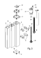
- a total of a lifting column which, for example, as a height-adjustable furniture leg, for example a table leg with table legs 47, as it is in Fig. 8 is exemplified, is used.
- the telescopic lifting column 1 in this case has three nested column profiles 4, 5, 6, which hide the drive unit accommodated therein from the outside.
- connection plate 12 is inserted, with which the lifting column 1 can be fastened, for example, on the underside of a table top 46.
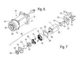
- connection plate 12 is embedded in a pocket 44 integrally formed at the upper end of the column profile 6 and preferably by means of screws 22, shown in the exploded view of the drive unit 37 Fig. 7 , screwed.
- the drive unit 37 is screwed with screws 13.
- an output shaft 30 is at the opposite end of the connecting plate 12 of the drive unit 37 as part of a planet carrier 18 of the gear unit 42 shown, on which a first spindle adapter 20 is placed, which engages in the inner contour of a drive tube 24 and this drives.
- the drive tube 24 is surrounded by the innermost first pillar profile 6.
- a first spindle 26 is moved, which is coupled via a first rotationally secured spindle nut 28 and a first driver 7 with the first pillar profile 6.
- This first spindle 26 is preferably formed as a hollow spindle, in which a preferably designed as a full spindle second spindle 27 in the longitudinal direction Z is movable.
- the second spindle 27 is coupled via a second rotationally secured spindle nut 29 and a second driver 8 with the second pillar profile 5, in which the first pillar profile 6 in the longitudinal direction of the drive tube 24 is movable.
- the lifting column 1 has a third pillar profile 4, which surrounds the second spindle 27 via a foot adapter 9 attached to one end of the second spindle 27 and in which the second pillar profile 5 can be moved in the longitudinal direction of the drive tube 24.
- the third pillar profile 4 In the retracted position of the lifting column 1 is thus substantially only the third pillar profile 4 can be seen, in which the other pillar profiles 5 and 6 are retracted and only slightly protrude at the top, the connection plate 12 near end.
- connection plate 12 near the upper end of the outer pillar profile 4 and the central pillar profile 5 is preferably covered by frames 2 and 3.
- the two frames 2 and 3 are inserted from above into the column profiles 4 and 5 and glued and serve in addition to the cover of the upper edge of the column profiles 4, 5 and the leadership of each in the outer column profile 4 and 5 movably arranged inner pillar profile 5 and 6.
- the length of the drive tube 24 is dimensioned such that the drive unit 37 can be integrated into the first column profile 6.
- the drive tube 24 is connected via a first spindle adapter 20 to the drive unit 37 and a second spindle adapter 25 with the first spindle formed as a hollow spindle 26, in such a way that the first spindle 26 with the same direction of rotation Drive tube 24 and in the longitudinal direction Z relative to the drive tube 24 is movable.
- the first spindle adapter 20 is attached to the output shaft 30 of the gear unit 42 and immersed in one of the outer contour of the first spindle adapter 20 adapted, preferably polygonal or polygon-like inner contour of the drive tube 24 a.
- polygon-like are to be understood as such "polygons" with odd pages, such as a polygon, in which at least one of the sides between two corners is not formed as a straight line, but, for example, as a concave or convex connecting line.
- the second spindle adapter 25 is preferably attached to an upper end of the first spindle 26 designed as a hollow spindle, preferably pressed.
- the outer contour of this second spindle adapter 25 preferably corresponds to that of the first spindle adapter 20, so that the drive tube 24 may be formed in the entire interior with the same inner contour.
- the second spindle 27 designed as a full spindle is connected via a third spindle adapter 35 to the first spindle 26 designed as a hollow spindle.
- This third spindle adapter 35 is attached to an upper end of the second spindle 27, in particular welded, and protrudes into a correspondingly shaped inner contour of the first spindle 26, so that the drive tube 24 and the first and the second spindle 26, 27 at the same speed and can be driven in rotation in the same direction of rotation, whereby the rotation results in a positive or negative longitudinal extent of the unit consisting of drive tube 24, first spindle 26 and second spindle 27 in the longitudinal direction Z relative to the drive tube 24.
- the third spindle adapter 35 is further closed by a square 53 with a side remote from one of the second spindle 27.
- a bearing foot 52 is attached, in particular welded (shown in FIGS Fig. 9a and 9c ), which is embedded in mounted on the foot adapter 9 state in the demandingadapter 9 and there rotatably mounted or supported in a thrust bearing, so that the second spindle 27 is rotatably mounted relative to the demandingadapter 9.
- both the spindle nuts 28, 29 and the drivers 7, 8 are formed in two parts.
- this has the significant advantage that the spindle nuts 28, 29 can be placed on the first or second spindle 26, 27 in a simple manner even after the pressing or welding of the spindle adapter 25, 35.
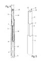
- the 4 and 5 once again show the lifting column 1 in a sectional view ( Fig. 4 ) and in a perspective view ( Fig. 5 ) in the extended state. Good to see here is the drive of the innermost pillar profile 6 and the central pillar profile 5 by the driver 7 and 8 respectively.
- the drive unit 37 accordingly consists essentially of a motor 11 and a gear unit 42, which is coupled via a motor shaft 38 to the motor 11.
- the closest to the engine 11 component of the transmission unit 42 is a ring gear 14 with an inclined internal toothing 41, in which a planet carrier 18 with planetary gears 19 received therein and an integrally arranged output shaft 30 rests.
- the gear unit 42 is closed by a gear plate 16.
- a torque motor can be selected as a direct drive.
- connection plate 12 At the adjacent to the connection plate 12 end face of the motor 11 a plurality of holes or screw holes are recessed in this back of the motor 11, which serve to attach the motor 11 to the connection plate 12, preferably by means of self-tapping screws 13. Also conceivable is the attachment of the motor 11 to the connection plate 12 by welded threaded bolts.
- the speed control of the motor 11 is preferably carried out by two integrated Hall sensors for detecting the rotational speed and direction of rotation.
- the motor shaft 38 is preferably provided with an integrated, obliquely toothed right-hand sun gear.
- a torque sensor 17 is preferably fixed axially.
- This snapshot 17 preferably has two inner displays 40, which engage in correspondingly shaped grooves of the ring gear 14. Furthermore, the torque sensor 17 has a plurality of, in particular four outer exhibitions 39, which engage in corresponding counter-elements of the upper, innermost column profile 6.
- the torque sensor 17 has a plurality of, in particular four outer exhibitions 39, which engage in corresponding counter-elements of the upper, innermost column profile 6.
- the pickup 17 was deliberately not integrated in the ring gear 14, so that when changing the column profile 6 only the snubber 17, but not the ring gear 14 of the gear unit 42 are replaced would. Via fastening means, preferably screws 15, the ring gear 14 is attached to the motor 11.
- the planet carrier 18 are, as in Fig. 7 shown, preferably three planet gears 19 added.
- the planet carrier 18 is preferably designed in one piece with an integrated output shaft 30.
- the planet carrier 18 has an insertion bevel on which the spindle adapter 20 can be slidably mounted in its functional position on the output shaft of the planet carrier.
- the output shaft 30 of the planet carrier 18 is preferably designed in the form of a hexalobular. Due to the design of the output shaft 30 in this form is a better, in particular more uniform load transfer and lower surface pressure in the contact area to the first spindle adapter 20 and ensures a flat load transfer.
- the planet gears 19 have over the planetary axles 21 a clearance fit.
- the planetary axles 21 have over the planet carrier 18 on one side a clearance fit and on the other side a press fit, which prevents the planetary gears 19 are clamped between the two webs of the planet carrier 18, whereby increased friction would arise.
- An excessive displacement of the planetary axes 21 in the direction of the spindles 26, 27 is prevented by the fact that the planetary axles 21 are supported on the transmission plate 16 before they have moved too far out of the planet carrier 18 out.
- the planetary axles 21 accordingly have a greater overlap in the interference fit than play in the direction of the transmission plate 16.
- the first spindle adapter 20 preferably has a recess 36 designed as a hexagonal recess, as a result of which an improved load transfer is achieved and lower surface pressure in the contact area to the planet carrier 18 is ensured.
- the internal hexagon 34 of the first spindle adapter 20 preferably has a rounded, bulbous shape.
- a splined connection is preferably provided for load transfer between the first spindle adapter 20 and the drive tube 24 .
- connection plate 12 To connect the lifting column 1 to, for example, the underside of a table, serves, as mentioned above, the connection plate 12. This is screwed with preferably self-tapping screws 22 with the pillar profile 6.
- the connection plate 12 preferably dips completely into a milled out pocket 44 of the pillar profile 6 and is therefore not visible in the installed state from the outside.
- a recess 31 for positioning a decoupling element 10 is provided in the connection plate 12.
- the attachment plate 12 further includes a groove for passing a motor cable 32, at the end of which a plug 33 is mounted to connect the motor 11 to a power source.
- the connection plate 12 preferably has a cable channel, through which the motor cable can be led out centrally on one side of the connection plate 12.
- a recess and two mounting holes are further provided laterally, in which a bracket 23 can be mounted. This bracket 23 is clamped captive after assembly between the connection plate 12 and the column profile 6, so that pulling out of the motor cable 32 is effectively prevented from the cable channel.
- the connection plate preferably has a plurality of threads for connecting a table top 46.
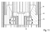
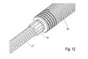
- the Fig. 10 to 13 show again the connection between the drive tube 24 and the hollow spindle formed as the first spindle 26 through the second spindle adapter 25 which is attached to one end of the first spindle 26 and in the hollow profile of the drive tube 24 is arranged rotationally fixed ( Fig. 10 and 11 ).
- the Fig. 12 and 13 show corresponding perspective and sectional views of the connection between the formed as a hollow spindle first spindle 26 and formed as a full spindle second spindle 27 through the third spindle adapter 35, which is also rotationally fixed in an inner contour of the first spindle 26 in the direction of the longitudinal extent of the spindles 26, 27 movable ,
- the outer thread diameter of the first spindle 26 is greater than the outer thread diameter of the second spindle 27 according to one embodiment variant. Both spindles 26, 27 preferably have the same thread pitch. It is also conceivable, however, that the first spindle 26 has a different thread pitch from the second spindle 27 in order to be able to retract or extend faster at the same rotational speed of one of the column profiles 5, 6.
- the pitch angle of the thread of the first spindle 26 is also possible to make the pitch angle of the thread of the first spindle 26 smaller than the pitch angle of the thread of the second spindle 27 and additionally a pressed onto the first spindle 26 sliding bearing 43 between the first spindle 26 and second spindle 27 to be arranged on a rotationally fixed Washer 48 is supported.
- the pairing of the thread pitches of the spindles 26, 27 with the spindle nuts 28, 29 and the bearing points of the spindles 26, 27 designed to be self-locking so as not to let the standing load of a selected height position of the lifting column be borne solely by the drive unit. In addition to the self-locking, the greatest possible efficiency is realized by this structural design.
Landscapes
- Transmission Devices (AREA)
- Legs For Furniture In General (AREA)
Applications Claiming Priority (1)
| Application Number | Priority Date | Filing Date | Title |
|---|---|---|---|
| DE102011055416.5A DE102011055416B4 (de) | 2011-11-16 | 2011-11-16 | Teleskopierbare Hubsäule eines Möbelteils |
Publications (2)
| Publication Number | Publication Date |
|---|---|
| EP2594157A2 true EP2594157A2 (fr) | 2013-05-22 |
| EP2594157A3 EP2594157A3 (fr) | 2014-12-10 |
Family
ID=47143686
Family Applications (1)
| Application Number | Title | Priority Date | Filing Date |
|---|---|---|---|
| EP12191279.4A Withdrawn EP2594157A3 (fr) | 2011-11-16 | 2012-11-05 | Colonne élévatrice télescopique d'une partie de meuble |
Country Status (2)
| Country | Link |
|---|---|
| EP (1) | EP2594157A3 (fr) |
| DE (1) | DE102011055416B4 (fr) |
Cited By (13)
| Publication number | Priority date | Publication date | Assignee | Title |
|---|---|---|---|---|
| WO2015047130A1 (fr) * | 2013-09-30 | 2015-04-02 | Кристина Андреевна ДУБИНИНА | Système de construction de meuble montable-démontable (variantes) |
| EP3011864A1 (fr) * | 2014-10-24 | 2016-04-27 | SUSPA GmbH | Procede de reglage en hauteur d'un premier element par rapport a un second element, complement d'equipement pour un tel dispositif et systeme reglable en hauteur comprenant plusieurs dispositifs dudit type |
| WO2016079021A1 (fr) * | 2014-11-21 | 2016-05-26 | Logicdata Electronic & Software Entwicklungs Gmbh | Système formant meuble à actionneur linéaire |
| CN106966345A (zh) * | 2017-01-10 | 2017-07-21 | 浙江捷昌线性驱动科技股份有限公司 | 一种可伸缩的传动总成装置及升降立柱 |
| WO2018054401A1 (fr) | 2016-09-20 | 2018-03-29 | BORCAD Medical a.s. | Colonne support télescopique d'un dispositif médical |
| US20180172062A1 (en) * | 2016-12-20 | 2018-06-21 | Zhejiang Jiecang Linear Motion Technology Co., Ltd. | Telescopic transmission assembly and lifting column using same |
| CN108741624A (zh) * | 2018-07-09 | 2018-11-06 | 宁波汇五洲智能科技有限公司 | 一种双电机正装圆管三节升降桌 |
| DE102017217769A1 (de) * | 2017-10-06 | 2019-04-11 | Suspa Gmbh | Teleskopierbare Säule und Montageprofil für eine derartige Säule |
| CN111480973A (zh) * | 2020-04-27 | 2020-08-04 | 珠海市润星泰电器有限公司 | 一种伸缩支柱及伸缩设备 |
| WO2021023166A1 (fr) * | 2019-08-02 | 2021-02-11 | 浙江捷昌线性驱动科技股份有限公司 | Colonne de levage à cinq segments |
| CN114314451A (zh) * | 2021-12-24 | 2022-04-12 | 乐歌人体工学科技股份有限公司 | 一种线性传动总成及升降立柱 |
| WO2022188526A1 (fr) * | 2021-03-10 | 2022-09-15 | 宁波海仕凯驱动科技有限公司 | Bureau réglable en hauteur |
| WO2024140321A1 (fr) * | 2022-12-26 | 2024-07-04 | 浙江联宜电机有限公司 | Mécanisme de levage pour table de levage, et table de levage |
Families Citing this family (3)
| Publication number | Priority date | Publication date | Assignee | Title |
|---|---|---|---|---|
| DE202013011430U1 (de) * | 2013-12-20 | 2015-03-23 | Grass Gmbh | Getriebemodul für eine Antriebsvorrichtung eines bewegbaren Möbelteils, Antriebsvorrichtung sowie ein Möbel |
| DE202016103880U1 (de) * | 2016-07-18 | 2017-10-19 | Paul Hettich Gmbh & Co. Kg | Hubsäule für höhenverstellbare Möbel und Möbel |
| CN110594251A (zh) * | 2019-08-02 | 2019-12-20 | 浙江捷昌线性驱动科技股份有限公司 | 一种四节升降立柱 |
Citations (1)
| Publication number | Priority date | Publication date | Assignee | Title |
|---|---|---|---|---|
| EP1097657B1 (fr) | 1999-11-03 | 2004-02-04 | Dewert Antriebs- und Systemtechnik GmbH & Co. KG | Unité téléscopique d'entraínement |
Family Cites Families (5)
| Publication number | Priority date | Publication date | Assignee | Title |
|---|---|---|---|---|
| DE102004004145B3 (de) | 2004-01-28 | 2005-09-29 | Neff Antriebstechnik Automation Gmbh | Verfahren zur Herstellung einer Spindelmutter mit Gangumlenkung für einen Kugelgewindetrieb und Kugelgewindetrieb mit Gangumlenkung |
| DE102004025683A1 (de) | 2004-05-26 | 2005-12-15 | Ina-Schaeffler Kg | Spindelmutter für einen Kugelgewindetrieb |
| DE202006008307U1 (de) | 2006-05-24 | 2006-08-31 | T-MOTION Technology Co., Ltd., Xindian City | Hubvorrichtung mit Gewindestangen |
| EP2301382A1 (fr) | 2009-09-25 | 2011-03-30 | Siemens AB | Colonne télescopique pour le réglage de la hauteur |
| DE102010000970C5 (de) | 2010-01-18 | 2022-10-13 | Suspa Gmbh | Höhenverstellbare Betätigungs-Einrichtung |
-
2011
- 2011-11-16 DE DE102011055416.5A patent/DE102011055416B4/de active Active
-
2012
- 2012-11-05 EP EP12191279.4A patent/EP2594157A3/fr not_active Withdrawn
Patent Citations (1)
| Publication number | Priority date | Publication date | Assignee | Title |
|---|---|---|---|---|
| EP1097657B1 (fr) | 1999-11-03 | 2004-02-04 | Dewert Antriebs- und Systemtechnik GmbH & Co. KG | Unité téléscopique d'entraínement |
Cited By (22)
| Publication number | Priority date | Publication date | Assignee | Title |
|---|---|---|---|---|
| WO2015047130A1 (fr) * | 2013-09-30 | 2015-04-02 | Кристина Андреевна ДУБИНИНА | Système de construction de meuble montable-démontable (variantes) |
| CN107072392A (zh) * | 2014-10-24 | 2017-08-18 | 苏斯帕有限公司 | 对第一部件相对第二部件调节高度的装置、用于该装置的补充装备件及包括多个装置的高度可调的系统 |
| EP3011864A1 (fr) * | 2014-10-24 | 2016-04-27 | SUSPA GmbH | Procede de reglage en hauteur d'un premier element par rapport a un second element, complement d'equipement pour un tel dispositif et systeme reglable en hauteur comprenant plusieurs dispositifs dudit type |
| WO2016062841A1 (fr) * | 2014-10-24 | 2016-04-28 | Suspa Gmbh | Dispositif de réglage en hauteur d'un premier élément par rapport à un deuxième élément, kit de rééquipement pour un dispositif de ce type, ainsi que système réglable en hauteur comprenant plusieurs dispositifs de ce type |
| US20170328449A1 (en) * | 2014-11-21 | 2017-11-16 | Logicdata Electronic & Software Entwicklungs Gmbh | Furniture system having a linear actuator |
| WO2016079021A1 (fr) * | 2014-11-21 | 2016-05-26 | Logicdata Electronic & Software Entwicklungs Gmbh | Système formant meuble à actionneur linéaire |
| US10502295B2 (en) | 2014-11-21 | 2019-12-10 | Logicdata Electronic & Software Entwicklungs Gmbh | Furniture system having a linear actuator |
| WO2018054401A1 (fr) | 2016-09-20 | 2018-03-29 | BORCAD Medical a.s. | Colonne support télescopique d'un dispositif médical |
| US20180172062A1 (en) * | 2016-12-20 | 2018-06-21 | Zhejiang Jiecang Linear Motion Technology Co., Ltd. | Telescopic transmission assembly and lifting column using same |
| EP3339684A1 (fr) * | 2016-12-20 | 2018-06-27 | Zhejiang Jiecang Linear Motion Technology Co., Ltd | Ensemble de transmission télescopique et colonne de levage utilisant celui-ci |
| US10436242B2 (en) | 2016-12-20 | 2019-10-08 | Zhejiang Jiecang Linear Motion Technology Co., Ltd. | Telescopic transmission assembly and lifting column using same |
| CN106966345A (zh) * | 2017-01-10 | 2017-07-21 | 浙江捷昌线性驱动科技股份有限公司 | 一种可伸缩的传动总成装置及升降立柱 |
| DE102017217769B4 (de) | 2017-10-06 | 2021-12-09 | Suspa Gmbh | Teleskopierbare Säule |
| DE102017217769A1 (de) * | 2017-10-06 | 2019-04-11 | Suspa Gmbh | Teleskopierbare Säule und Montageprofil für eine derartige Säule |
| CN108741624A (zh) * | 2018-07-09 | 2018-11-06 | 宁波汇五洲智能科技有限公司 | 一种双电机正装圆管三节升降桌 |
| CN108741624B (zh) * | 2018-07-09 | 2024-03-01 | 宁波汇五洲智能科技有限公司 | 一种双电机正装圆管三节升降桌 |
| WO2021023166A1 (fr) * | 2019-08-02 | 2021-02-11 | 浙江捷昌线性驱动科技股份有限公司 | Colonne de levage à cinq segments |
| CN111480973A (zh) * | 2020-04-27 | 2020-08-04 | 珠海市润星泰电器有限公司 | 一种伸缩支柱及伸缩设备 |
| CN111480973B (zh) * | 2020-04-27 | 2022-04-12 | 珠海市润星泰电器有限公司 | 一种伸缩支柱及伸缩设备 |
| WO2022188526A1 (fr) * | 2021-03-10 | 2022-09-15 | 宁波海仕凯驱动科技有限公司 | Bureau réglable en hauteur |
| CN114314451A (zh) * | 2021-12-24 | 2022-04-12 | 乐歌人体工学科技股份有限公司 | 一种线性传动总成及升降立柱 |
| WO2024140321A1 (fr) * | 2022-12-26 | 2024-07-04 | 浙江联宜电机有限公司 | Mécanisme de levage pour table de levage, et table de levage |
Also Published As
| Publication number | Publication date |
|---|---|
| DE102011055416B4 (de) | 2022-09-29 |
| DE102011055416A1 (de) | 2013-05-16 |
| EP2594157A3 (fr) | 2014-12-10 |
Similar Documents
| Publication | Publication Date | Title |
|---|---|---|
| EP2594157A2 (fr) | Colonne élévatrice télescopique d'une partie de meuble | |
| EP2951078B1 (fr) | Colonne de direction pour véhicule automobile | |
| EP2146114B1 (fr) | Entraînement à double broche télescopique | |
| DE102010000970B4 (de) | Höhenverstellbare Betätigungs-Einrichtung | |
| DE102012102298B4 (de) | Linearaktuator und höhenverstellbarer Tisch | |
| DE102018119426B4 (de) | Verstellbare Hubsäule und verstellbares Tischsystem | |
| DE29919877U1 (de) | Elektromotorische Verstelleinrichtung | |
| CH664434A5 (de) | Teleskopsaeule mit elektromotorischem antrieb und moebel mit der teleskopsaeule als fuss. | |
| DE29919214U1 (de) | Elektromotorischer Möbelantrieb | |
| DE102007025215A1 (de) | Höhenverstellbare Säule, insbesondere für Tische | |
| DE102008060043B3 (de) | Spindelpresse | |
| DE102012010547B4 (de) | Rangierantrieb für einen Anhänger | |
| EP1584264B1 (fr) | Système d'entrainement réglable en hauteur notamment pour meubles | |
| DE202004001054U1 (de) | Höhenverstellbare Stütze für Sattelauflieger o.dgl. | |
| DE202006008307U1 (de) | Hubvorrichtung mit Gewindestangen | |
| WO2015107055A1 (fr) | Appui réglable en hauteur pour un véhicule | |
| DE102006035915A1 (de) | Hubeinrichtung | |
| EP1820600B1 (fr) | Broche de perçage pour centre de traitement horizontal ou vertical dotée d'un entraînement intérieur à puissance dérivée | |
| AT504322B1 (de) | Stelleinrichtung zum positionieren einer last | |
| EP1604589A1 (fr) | Dispositif de réglage de la hauteur d'une table | |
| DE19920672B4 (de) | Lineare Stellvorrichtung | |
| DE102005016430A1 (de) | Hubvorrichtung | |
| EP2594156B1 (fr) | Colonne élévatrice télescopique d'une partie de meuble | |
| EP1097657A1 (fr) | Unité téléscopique d'entraínement | |
| DE202005021004U1 (de) | Höhenverstellbarer Antrieb, insbesondere für Möbel |
Legal Events
| Date | Code | Title | Description |
|---|---|---|---|
| PUAI | Public reference made under article 153(3) epc to a published international application that has entered the european phase |
Free format text: ORIGINAL CODE: 0009012 |
|
| AK | Designated contracting states |
Kind code of ref document: A2 Designated state(s): AL AT BE BG CH CY CZ DE DK EE ES FI FR GB GR HR HU IE IS IT LI LT LU LV MC MK MT NL NO PL PT RO RS SE SI SK SM TR |
|
| AX | Request for extension of the european patent |
Extension state: BA ME |
|
| PUAL | Search report despatched |
Free format text: ORIGINAL CODE: 0009013 |
|
| AK | Designated contracting states |
Kind code of ref document: A3 Designated state(s): AL AT BE BG CH CY CZ DE DK EE ES FI FR GB GR HR HU IE IS IT LI LT LU LV MC MK MT NL NO PL PT RO RS SE SI SK SM TR |
|
| AX | Request for extension of the european patent |
Extension state: BA ME |
|
| RIC1 | Information provided on ipc code assigned before grant |
Ipc: A47B 9/04 20060101AFI20141106BHEP |
|
| 17P | Request for examination filed |
Effective date: 20150603 |
|
| RBV | Designated contracting states (corrected) |
Designated state(s): AL AT BE BG CH CY CZ DE DK EE ES FI FR GB GR HR HU IE IS IT LI LT LU LV MC MK MT NL NO PL PT RO RS SE SI SK SM TR |
|
| STAA | Information on the status of an ep patent application or granted ep patent |
Free format text: STATUS: THE APPLICATION HAS BEEN WITHDRAWN |
|
| 18W | Application withdrawn |
Effective date: 20170907 |
|
| R18W | Application withdrawn (corrected) |
Effective date: 20170830 |