EP2872022B1 - Halter für bezüge von wischmops - Google Patents
Halter für bezüge von wischmops Download PDFInfo
- Publication number
- EP2872022B1 EP2872022B1 EP12737269.6A EP12737269A EP2872022B1 EP 2872022 B1 EP2872022 B1 EP 2872022B1 EP 12737269 A EP12737269 A EP 12737269A EP 2872022 B1 EP2872022 B1 EP 2872022B1
- Authority
- EP
- European Patent Office
- Prior art keywords
- folding
- folding wings
- holder
- stop
- contact portion
- Prior art date
- Legal status (The legal status is an assumption and is not a legal conclusion. Google has not performed a legal analysis and makes no representation as to the accuracy of the status listed.)
- Active
Links
Images


Classifications
-
- A—HUMAN NECESSITIES
- A47—FURNITURE; DOMESTIC ARTICLES OR APPLIANCES; COFFEE MILLS; SPICE MILLS; SUCTION CLEANERS IN GENERAL
- A47L—DOMESTIC WASHING OR CLEANING; SUCTION CLEANERS IN GENERAL
- A47L13/00—Implements for cleaning floors, carpets, furniture, walls, or wall coverings
- A47L13/10—Scrubbing; Scouring; Cleaning; Polishing
- A47L13/20—Mops
- A47L13/24—Frames for mops; Mop heads
- A47L13/254—Plate frames
- A47L13/258—Plate frames of adjustable or foldable type
-
- A—HUMAN NECESSITIES
- A47—FURNITURE; DOMESTIC ARTICLES OR APPLIANCES; COFFEE MILLS; SPICE MILLS; SUCTION CLEANERS IN GENERAL
- A47L—DOMESTIC WASHING OR CLEANING; SUCTION CLEANERS IN GENERAL
- A47L13/00—Implements for cleaning floors, carpets, furniture, walls, or wall coverings
- A47L13/10—Scrubbing; Scouring; Cleaning; Polishing
- A47L13/20—Mops
- A47L13/24—Frames for mops; Mop heads
- A47L13/25—Wire frames
- A47L13/253—Wire frames of adjustable or foldable type
Definitions
- the present invention relates to a holder for covers of mops.
- a mop is a cleaning device that has a pivotally mounted bottom plate attached to a long handle.
- a mop cover is provided, which can be moved over the ground. This is stretched by the bottom plate and thus lies substantially taut on this.
- the shape of the mop cover is predetermined by the bottom plate and this is substantially flat, and the mop cover has a substantially flat surface. This can be wiped over the surface to be cleaned, which makes it easy to clean large floor surfaces. This is particularly supported by the fact that the mop cover is often provided with fringes, which are normally up to about 10 cm long.
- the mop cover can also be soaked with water, which may also contain a cleaning agent, whereby the cleaning effect is enhanced.
- the bottom plate substantially in the form of an elongated rectangle, which can be folded with respect to its longitudinal direction. As a result, the longitudinal ends come close together. In such a condition, a suitably sized mop cover having pockets at its longitudinal ends may be slid over the longitudinal ends of the folded bottom panel.
- this bottom plate is now transferred from the folded state to the flat state, the mop cover is pulled straight through the pockets and through the bottom plate and also held by them, d. H. he can not slip off the bottom plate.
- by refolding the bottom plate it is easy to remove the cover from it.
- a holder for holding mop mops is known, the wiper plate of which has plate wings which can be locked in a spread position.
- This lock occurs automatically when the wiper plate is pressed against the floor.
- an actuatable over the foot rocker is provided. If you push down the end of the rocker, a rocker arm is pushed up. This rocker arm presses against a retaining element and causes the first locking lug out of engagement with the associated axis. This allows the plate wing to move down.
- the DE 295 19 320 U1 represents the closest prior art.
- the present invention aims to provide a holder for a mop which is designed so that the mop cover is easily replaceable.
- a holder for holding mop covers for cleaning means comprises a central part, two lockable folding wings, which are pivotally mounted on the central part, a locking device which can lock the two folding wings in a pivotal position relative to the central part, and means to the Detach lock the locked folding wings with respect to the central part, so that the folding wings can be pivoted.
- the bottom plate of the mop is divided into three parts. On the one hand, there is a middle section, which lies between the two folding wings.
- the folding wings can be pivoted about this central part, so that they can be pivoted between a first configuration in which the two folding wings and the central part together form a plane on its underside (planar configuration), and a second configuration in which the two folding wings together form a substantially U-shaped shape with the middle part.
- a mop cover can be mounted on the holder. This mop cover is held by existing at its ends pockets in the first configuration by the holder and thus can no longer slip down from this unintentionally.
- the pivotable mounting of the folding wings with respect. Of the middle part can be done for example by an axle bearing, but it can also be done by the fact that the folding wings are connected to the middle part by means of a flexible connector.
- the locking device ensures that the two folding wings can be kept in the first configuration, ie a position in which the holder is a flat Bottom plate forms and does not unintentionally "folds".
- a feature of the present invention is that the locking device is biased to the state in which the two folding wings are locked.
- the holder locks when the lock is released when moving the two folding wings toward a state in which the lower surfaces of the two folding wings are substantially in a plane, the folding wings automatically by means of the locking device.
- the locking device for at least one of the folding wings preferably for both, a stop on the folding wing and a relative to the central part movably provided part of the plant, which has at least one partial investment stop.
- the stop on the folding wing and the plant sub-stop when locking the folding wing are engaged, while they disengage upon release of the lock by moving the system part.
- a system part is provided, to which the respective folding wing / the folding wings can abut when locking.
- the contact part is movable substantially parallel to the pivot axis of the folding leaf.
- the contact part is movable only substantially parallel to the pivot axis of the folding wing, d. H. that you can not move this or only slightly in another direction.
- An advantage of this feature taken by itself is that it ensures a good and easy demolding of the plant part.
- it will be easier for a cleaning specialist to find it easier to remove a piece of equipment essentially parallel to the pivot axis of the folding wings after a relatively long work, for example, than would be possible along a direction of the handle.
- the means for releasing the locking of the folding wings with respect to the central part comprises a manually operable push-button. If one operates this leads, if sufficiently strong operation, to solve the lock.
- the push button is coupled to the system part.
- the push button results in actuation to a movement of the system part, which in turn triggers the lock when displaced by a predetermined path.
- there is a push button on the holder which allows a release of the lock, so to speak "by pressing a button”. Since this is coupled to the plant part, this is a easy solution of the lock allows.
- system part and the push button is formed in one piece, d. H. that these consist of a single component. This allows a simple design of the mop, it is now no complicated coupling between the system part and push button needed.
- the direction “down” refers to the direction perpendicular to the holder extends from the side on which a plane is formed in the locked state by the central part and the two folding wings. In other words, it is that side which, in use, is opposite a stem and, if necessary, a handle connected to the holder. In this respect, it is the side of the holder, which rests on the surface to be cleaned in normal use.
- the stop on the folding wing is preferably aligned such that it rests flat in the locked state of the folding leaf on the plant sub-stop.
- the Verschwenkungs Surrey is limited so that the folding wings must include a minimum angle with each other. This means that they include an angle of at least 10 °, preferably 20 °, more preferably 30 ° with the direction downwards in the unlocked state.
- the two folding wings enclose an angle of approximately 60 °, ie approximately 55 ° to 65 °, symmetrical to the direction downwards. This prevents the folding wings from completely falling down after releasing the lock.
- Said Verschwenkungs Symposium-restricting means advantageously has a central part stop, which is provided stationary with respect to the central part. This means that there is a further stop at the central part, which can engage the associated folding wing, in particular preferably the already defined stop of the folding wing, in the unlocked state.
- the Verschwenk Scheme is restricted in a simple manner, but at the same time reliable. The simple design of this device can reduce production costs.
- the automatic locking takes place in the state in which the lower surfaces of the two lockable folding wings lie substantially in one plane. This ensures the usability of the pug in the locked state.
- a handle is provided on the central part, which is pivotable about two axes with respect to the central part and preferably in a rotational position about an axis.
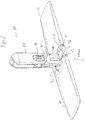
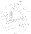
- FIG. 1 FIG. 4 illustrates an exploded view of the holder 10 according to the present invention. The assembled holder 10 is shown in FIG FIG. 2 to see.
- This holder 10 has a handle 28 which is rotatably mounted on an intermediate part 34. This rotatable or pivotable mounting can be locked relative to a pivot axis by means of a locking device 30 in a pivoting position.
- the central part 12 is provided by means of a pivot axis 32.
- two folding wings 14 are mounted by means of two axes.
- a push button 20 is further provided movable, which is partially received in a groove 13 of the central part 12 on the side of the handle 28.
- the handle 28 opposite surfaces of the folding wings 14 and the central portion 12 form the surface which abuts when using the holder in a mop, together with the attached mop cover to the surface to be cleaned.
- the push button 20 itself serves to actuate or to solve the locking device, which will be described in detail later. It is slidably received in the groove 13, but in addition it is received in a hollow cap 21 which is formed on the central part 12 on the side of the groove 13. As such, it is received along a circumferential direction of the central portion 12, wherein he however, protrudes from the central part 12. In this respect he is easily operated from the outside. The details will be described later.
- the two folding wings 14 are flat, plate-like elements whose basic shape is substantially rectangular. On a narrow side of the rectangles, which lies outside when holding a mop cover, they have a substantially smooth edge. On the opposite side provided with through holes projections are provided which can be connected to the central part 12. In this case, the through holes are aligned so that in each of the projections, a through hole is provided which extends parallel to the narrow side of the flap and which has the same diameter for each projection. The through holes are aligned with each other, so that through these through holes a single pivot axis 22 can be passed. These holes are used to connect the respective flap 14 with the central part 12.
- the projection 18a plays a role in the locking of the folding wings 14 with respect to the central part 12.
- This projection 18a is provided at such a position of the projected narrow side of the folding wing 14 that it can penetrate into a later-mentioned passage 19 of the central part.
- At its longitudinal end, it has a bevelled surface 18, which extends in an assembled holder 10 obliquely downwards.
- the middle part 12 is a body that can be described essentially as a two-part.
- a flat, rectangular part on the longitudinal sides of the narrow-side projections and recesses of the folding wings 14 matching recesses and Projections are provided. These projections are provided with through holes that fit to the through holes in the flaps 14, so that rod-like pivot axes 22 can be inserted through them, whereby the folding wings 14 are pivotally connected to the central part 12.
- This attachment 21 is formed integrally with the lower part and has substantially the shape of a cuboid with rounded corners.
- a groove 13 is formed in the flat, rectangular part of the middle part 12, which in cross section has a trapezoidal shape, which tapers downwards.
- This groove 13 extends along the longitudinal direction of the flat, rectangular portion of the central portion 12 of the cap 21 to the opening of the attachment 21 opposite end of the central portion 12th
- two bores 33 are further provided in the attachment 21, which extend parallel to the underside of the central part 12. These pass through the walls of the cavity defined by the attachment 21 in alignment.
- the push button 20 is used in the assembled state.
- This push button 20 has the shape of a hollow body which is open on one side. One could also call this form a hollow cuboid, with one side open.
- the push button 20 is inserted with this open side opposite the closed side of the attachment 21 into the cavity of the attachment 21.
- the push button 20 also has on the two sides, which face the holes 33 after insertion into the attachment 21, each holes 37, which are aligned with the holes 33. However, these holes 37 are elongated. The longitudinal direction of these elongated holes 37 is, after insertion of the push button 20, parallel to the longitudinal direction of the central part 12. Thus, one can use through the holes 33 and 37, an axis 32, without preventing the push button 20, with respect to the attachment 21 along the longitudinal direction of the central portion 12 to be moved.
- a spring 36 which serves to bias the push button 20 toward the opening of the cap 21, d. H. this spring pushes the push button 20 to the outside.
- the spring is, e.g. by corresponding projections in the push button 20 and top 21, held so that they can not slip with respect to these two components.
- the tension of the spring 36 is important in that it achieves the automatic locking previously described.
- a contact part 16 On the lower side of the push-button 20 when inserted into the attachment 21, there is a contact part 16, which has the shape of a trapezoid tapering downwards in cross-section perpendicular to the longitudinal direction of the middle part 12. This trapezoid fits into the groove 13 from the shape, ie you can use this projection in the groove 13 and move in this groove 13 along the longitudinal direction of the central part 12.
- this passage 19 allows, in addition to the already mentioned opening of the Attachment 21, a further access to the interior of the article 21.
- the passage 19 also divides the flat rectangular portion of the central portion 12 in two parts, thereby extending substantially parallel to the narrow sides of the flat rectangular portion. These two parts are held together by the attachment 21.
- an intermediate part 34 is placed at the top of essay 21, d. H. on the side opposite the bottom of the holder 10, an intermediate part 34 is placed.
- This intermediate part 34 has two arms 35, each having a bore. By means of this bore they can be connected to the attachment 21 and the push button 20. More specifically, the axle 32 is inserted through the bore of one of the arms 35 of the intermediate member 34. It then passes through the hole 33 of the cap 21 and through one of the holes 37 of the push button 20 therethrough. Then it passes through the other hole 37 of the push button 20 and through the associated hole 33 of the cap 21 therethrough, to finally penetrate into the other hole of the other arm 35 of the intermediate part 34. As a result, the intermediate part 34, the middle part 12 and the push button 20 are connected.
- the axis 32 not only has the task of providing a pivotable connection between the handle 28 and the holder 10, but also serves to prevent slipping out of the push button 20.
- the intermediate part 34 is another hole 34 a, via which the handle 28 is mounted pivotably with respect to the intermediate part 34.
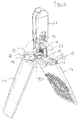
- FIG. 3 To better understand the locking mechanism, we will see below FIG. 3 to go into detail. In this Figurines are not all in anymore FIGS. 1 and 2 used reference numerals in order not to complicate an understanding.
- FIG. 3 will be one opposite the FIG. 2 enlarged partial sectional view of the holder 10 shown in the locked state.
- the lower sides of the folding wings 14 and the middle part 12 substantially form a plane.
- the push button 20 is pushed as far as possible to the outside, ie until the opening of the attachment 21 opposite edges of its holes 37 abuts the axis 32 and thereby prevents further movement of the push button 20.
- the abutment member 16 is located within the passage 19.
- an interaction with the projections 18a of the folding wings 14 is possible.
- the stops 18 of the folding wing 14 and the trapezoidal leg surfaces of the abutment part 16 lie flat against one another, so that a pivoting of the folding wings 14 downwards is prevented.
- the contact part 17 is moved out of the passage 19.
- an engagement of the stops 18 and system part stops 17 is no longer possible. This has the consequence that the lock is released, whereby the folding wings 14 can be pivoted.
- the system part stops 17 of the system part 16 together with the surfaces 18 of the projections 18a form the locking device.
- the surfaces 17 and 18a are, in the locked state, flat against each other. Since the surfaces 17 and, accordingly, the surfaces 18 in the locked state are directed obliquely downwards, the projections 18a can not be pivoted upwards. Furthermore, pivoting of the projections 18a downwards is prevented by a similar arrangement. This has the consequence that in the folding wings 14 of that part which extends from the pivot axes 22 to the outside, can not be moved down in the locked state. In this respect, a pivoting of the folding wings 14 is prevented in this state, the holder is thus, as regards the positioning of the folding wings 14 with respect to the central part 12, locked. Now, as is the case, ensuring that the lower surfaces of the folding wings 14 and the middle part 12 form a plane, the holder can thus be used well for holding mop covers and thus for cleaning surfaces without the holder 10 significantly deformed.
Landscapes
- Cleaning Implements For Floors, Carpets, Furniture, Walls, And The Like (AREA)
Applications Claiming Priority (1)
| Application Number | Priority Date | Filing Date | Title |
|---|---|---|---|
| PCT/EP2012/063887 WO2014012569A1 (de) | 2012-07-16 | 2012-07-16 | Halter für bezüge von wischmops |
Publications (2)
| Publication Number | Publication Date |
|---|---|
| EP2872022A1 EP2872022A1 (de) | 2015-05-20 |
| EP2872022B1 true EP2872022B1 (de) | 2016-08-31 |
Family
ID=46545375
Family Applications (1)
| Application Number | Title | Priority Date | Filing Date |
|---|---|---|---|
| EP12737269.6A Active EP2872022B1 (de) | 2012-07-16 | 2012-07-16 | Halter für bezüge von wischmops |
Country Status (6)
| Country | Link |
|---|---|
| US (1) | US9468354B2 (pl) |
| EP (1) | EP2872022B1 (pl) |
| DK (1) | DK2872022T3 (pl) |
| ES (1) | ES2604199T3 (pl) |
| PL (1) | PL2872022T3 (pl) |
| WO (1) | WO2014012569A1 (pl) |
Families Citing this family (6)
| Publication number | Priority date | Publication date | Assignee | Title |
|---|---|---|---|---|
| DE102014008954B3 (de) * | 2014-06-23 | 2015-09-10 | Carl Freudenberg Kg | Wischbezug und Wischgerät |
| NL2016570B1 (nl) * | 2016-04-08 | 2017-11-02 | Bahri Boudali | Reinigingskop, combinatie van een reinigingskop, een waterdoorlatende zak en schoonmaakmiddelen, en combinatie van een reinigingskop en een emmer met een pomp. |
| US10842343B2 (en) * | 2018-06-08 | 2020-11-24 | Contec Inc. | Cleaning tool with adjustable tensioner and related method |
| TWI657783B (zh) * | 2018-06-25 | 2019-05-01 | 丁明哲 | Folding flat mop |
| CN110623611B (zh) * | 2018-06-25 | 2021-03-12 | 丁明哲 | 折叠式平板拖把 |
| CN115211782A (zh) * | 2022-08-30 | 2022-10-21 | 浙江拓朴清洁科技有限公司 | 一种多功能拖把头 |
Family Cites Families (3)
| Publication number | Priority date | Publication date | Assignee | Title |
|---|---|---|---|---|
| DE4011713A1 (de) * | 1990-04-11 | 1991-10-17 | Ewu Ag | Reinigungsgeraet |
| IT239177Y1 (it) | 1995-01-26 | 2001-02-19 | Cervellin Sergio | Scopa ad umido del tipo a redazza |
| DE102005044507A1 (de) * | 2005-09-16 | 2007-03-22 | Leifheit Ag | Klappbare Wischerplatte |
-
2012
- 2012-07-16 PL PL12737269T patent/PL2872022T3/pl unknown
- 2012-07-16 ES ES12737269.6T patent/ES2604199T3/es active Active
- 2012-07-16 US US14/415,174 patent/US9468354B2/en active Active
- 2012-07-16 DK DK12737269.6T patent/DK2872022T3/da active
- 2012-07-16 WO PCT/EP2012/063887 patent/WO2014012569A1/de not_active Ceased
- 2012-07-16 EP EP12737269.6A patent/EP2872022B1/de active Active
Also Published As
| Publication number | Publication date |
|---|---|
| EP2872022A1 (de) | 2015-05-20 |
| US9468354B2 (en) | 2016-10-18 |
| US20150208894A1 (en) | 2015-07-30 |
| DK2872022T3 (da) | 2017-01-02 |
| PL2872022T3 (pl) | 2017-04-28 |
| ES2604199T3 (es) | 2017-03-03 |
| WO2014012569A1 (de) | 2014-01-23 |
Similar Documents
| Publication | Publication Date | Title |
|---|---|---|
| DE4110830C1 (pl) | ||
| EP2872022B1 (de) | Halter für bezüge von wischmops | |
| DE102006012754A1 (de) | Chirurgisches Instrument | |
| EP0451443A1 (de) | Reinigungsgerät | |
| DE69800777T2 (de) | Rollengepäck mit Schleppelement | |
| DE112017002710B4 (de) | Wischsystem | |
| EP3153115B1 (de) | Knochenstanze mit unverlierbarem stanzschieber | |
| DE3719984C2 (pl) | ||
| DE19653897B4 (de) | Führungsanordnung für ein Türelement | |
| DE10008331C2 (de) | Vorrichtung zum Auspressen von Flüssigkeit absorbierenden Wischkörpern | |
| DE10206854C1 (de) | Ausziehsperre für übereinander angeordnete Schubladen | |
| DE20010771U1 (de) | Adapter für einen Schraubaufsatz | |
| EP3048992B1 (de) | Chirurgischer retraktor mit abnehmbarem betätigungselement | |
| DE102005013901A1 (de) | Baumständer, insbesondere Christbaumständer mit verbesserter Lösefunktion | |
| EP1055487A1 (de) | Zange mit parallelen Backen | |
| DE2461003A1 (de) | Vorrichtung zum spreizen von federn bzw. kolbenringen oder dergleichen | |
| DE102019133319B4 (de) | Unterflurinstallationsbauteil | |
| CH716756B1 (de) | Montageeinrichtung zur lösbaren Montage eines Garniturteils auf einem WC-Körper. | |
| DE19931953A1 (de) | Beschlag zur Lagerung eines Endes einer Latte eines Lattenrahmens | |
| DE3809730C2 (pl) | ||
| DE4303993C2 (de) | Fußbodenwischer | |
| DE9106427U1 (de) | Heftzange | |
| DE69905359T2 (de) | Greifvorrichtung | |
| EP3251576B1 (de) | Wischsystem mit einem wischgerät und einer mobilen aufbewahrungsbox | |
| DE10000100C1 (de) | Vorrichtung zum Auf- und Abhängen von Vorhängen, sowie Vorhanghäkchen für diese Vorrichtung |
Legal Events
| Date | Code | Title | Description |
|---|---|---|---|
| PUAI | Public reference made under article 153(3) epc to a published international application that has entered the european phase |
Free format text: ORIGINAL CODE: 0009012 |
|
| 17P | Request for examination filed |
Effective date: 20150203 |
|
| AK | Designated contracting states |
Kind code of ref document: A1 Designated state(s): AL AT BE BG CH CY CZ DE DK EE ES FI FR GB GR HR HU IE IS IT LI LT LU LV MC MK MT NL NO PL PT RO RS SE SI SK SM TR |
|
| AX | Request for extension of the european patent |
Extension state: BA ME |
|
| DAX | Request for extension of the european patent (deleted) | ||
| GRAP | Despatch of communication of intention to grant a patent |
Free format text: ORIGINAL CODE: EPIDOSNIGR1 |
|
| INTG | Intention to grant announced |
Effective date: 20160329 |
|
| GRAS | Grant fee paid |
Free format text: ORIGINAL CODE: EPIDOSNIGR3 |
|
| GRAA | (expected) grant |
Free format text: ORIGINAL CODE: 0009210 |
|
| AK | Designated contracting states |
Kind code of ref document: B1 Designated state(s): AL AT BE BG CH CY CZ DE DK EE ES FI FR GB GR HR HU IE IS IT LI LT LU LV MC MK MT NL NO PL PT RO RS SE SI SK SM TR |
|
| REG | Reference to a national code |
Ref country code: CH Ref legal event code: EP Ref country code: GB Ref legal event code: FG4D Free format text: NOT ENGLISH |
|
| REG | Reference to a national code |
Ref country code: IE Ref legal event code: FG4D Free format text: LANGUAGE OF EP DOCUMENT: GERMAN |
|
| REG | Reference to a national code |
Ref country code: DE Ref legal event code: R096 Ref document number: 502012008139 Country of ref document: DE |
|
| REG | Reference to a national code |
Ref country code: AT Ref legal event code: REF Ref document number: 824191 Country of ref document: AT Kind code of ref document: T Effective date: 20161015 |
|
| REG | Reference to a national code |
Ref country code: NL Ref legal event code: FP |
|
| REG | Reference to a national code |
Ref country code: SE Ref legal event code: TRGR |
|
| REG | Reference to a national code |
Ref country code: LT Ref legal event code: MG4D |
|
| REG | Reference to a national code |
Ref country code: DK Ref legal event code: T3 Effective date: 20161222 |
|
| PG25 | Lapsed in a contracting state [announced via postgrant information from national office to epo] |
Ref country code: FI Free format text: LAPSE BECAUSE OF FAILURE TO SUBMIT A TRANSLATION OF THE DESCRIPTION OR TO PAY THE FEE WITHIN THE PRESCRIBED TIME-LIMIT Effective date: 20160831 Ref country code: RS Free format text: LAPSE BECAUSE OF FAILURE TO SUBMIT A TRANSLATION OF THE DESCRIPTION OR TO PAY THE FEE WITHIN THE PRESCRIBED TIME-LIMIT Effective date: 20160831 Ref country code: LT Free format text: LAPSE BECAUSE OF FAILURE TO SUBMIT A TRANSLATION OF THE DESCRIPTION OR TO PAY THE FEE WITHIN THE PRESCRIBED TIME-LIMIT Effective date: 20160831 Ref country code: HR Free format text: LAPSE BECAUSE OF FAILURE TO SUBMIT A TRANSLATION OF THE DESCRIPTION OR TO PAY THE FEE WITHIN THE PRESCRIBED TIME-LIMIT Effective date: 20160831 Ref country code: NO Free format text: LAPSE BECAUSE OF FAILURE TO SUBMIT A TRANSLATION OF THE DESCRIPTION OR TO PAY THE FEE WITHIN THE PRESCRIBED TIME-LIMIT Effective date: 20161130 |
|
| PG25 | Lapsed in a contracting state [announced via postgrant information from national office to epo] |
Ref country code: GR Free format text: LAPSE BECAUSE OF FAILURE TO SUBMIT A TRANSLATION OF THE DESCRIPTION OR TO PAY THE FEE WITHIN THE PRESCRIBED TIME-LIMIT Effective date: 20161201 Ref country code: LV Free format text: LAPSE BECAUSE OF FAILURE TO SUBMIT A TRANSLATION OF THE DESCRIPTION OR TO PAY THE FEE WITHIN THE PRESCRIBED TIME-LIMIT Effective date: 20160831 |
|
| REG | Reference to a national code |
Ref country code: ES Ref legal event code: FG2A Ref document number: 2604199 Country of ref document: ES Kind code of ref document: T3 Effective date: 20170303 |
|
| PG25 | Lapsed in a contracting state [announced via postgrant information from national office to epo] |
Ref country code: EE Free format text: LAPSE BECAUSE OF FAILURE TO SUBMIT A TRANSLATION OF THE DESCRIPTION OR TO PAY THE FEE WITHIN THE PRESCRIBED TIME-LIMIT Effective date: 20160831 Ref country code: RO Free format text: LAPSE BECAUSE OF FAILURE TO SUBMIT A TRANSLATION OF THE DESCRIPTION OR TO PAY THE FEE WITHIN THE PRESCRIBED TIME-LIMIT Effective date: 20160831 |
|
| PG25 | Lapsed in a contracting state [announced via postgrant information from national office to epo] |
Ref country code: SM Free format text: LAPSE BECAUSE OF FAILURE TO SUBMIT A TRANSLATION OF THE DESCRIPTION OR TO PAY THE FEE WITHIN THE PRESCRIBED TIME-LIMIT Effective date: 20160831 Ref country code: SK Free format text: LAPSE BECAUSE OF FAILURE TO SUBMIT A TRANSLATION OF THE DESCRIPTION OR TO PAY THE FEE WITHIN THE PRESCRIBED TIME-LIMIT Effective date: 20160831 Ref country code: BG Free format text: LAPSE BECAUSE OF FAILURE TO SUBMIT A TRANSLATION OF THE DESCRIPTION OR TO PAY THE FEE WITHIN THE PRESCRIBED TIME-LIMIT Effective date: 20161130 Ref country code: PT Free format text: LAPSE BECAUSE OF FAILURE TO SUBMIT A TRANSLATION OF THE DESCRIPTION OR TO PAY THE FEE WITHIN THE PRESCRIBED TIME-LIMIT Effective date: 20170102 Ref country code: CZ Free format text: LAPSE BECAUSE OF FAILURE TO SUBMIT A TRANSLATION OF THE DESCRIPTION OR TO PAY THE FEE WITHIN THE PRESCRIBED TIME-LIMIT Effective date: 20160831 |
|
| REG | Reference to a national code |
Ref country code: DE Ref legal event code: R097 Ref document number: 502012008139 Country of ref document: DE |
|
| PLBE | No opposition filed within time limit |
Free format text: ORIGINAL CODE: 0009261 |
|
| STAA | Information on the status of an ep patent application or granted ep patent |
Free format text: STATUS: NO OPPOSITION FILED WITHIN TIME LIMIT |
|
| REG | Reference to a national code |
Ref country code: FR Ref legal event code: PLFP Year of fee payment: 6 |
|
| 26N | No opposition filed |
Effective date: 20170601 |
|
| PG25 | Lapsed in a contracting state [announced via postgrant information from national office to epo] |
Ref country code: SI Free format text: LAPSE BECAUSE OF FAILURE TO SUBMIT A TRANSLATION OF THE DESCRIPTION OR TO PAY THE FEE WITHIN THE PRESCRIBED TIME-LIMIT Effective date: 20160831 |
|
| REG | Reference to a national code |
Ref country code: IE Ref legal event code: MM4A |
|
| PG25 | Lapsed in a contracting state [announced via postgrant information from national office to epo] |
Ref country code: IE Free format text: LAPSE BECAUSE OF NON-PAYMENT OF DUE FEES Effective date: 20170716 |
|
| REG | Reference to a national code |
Ref country code: BE Ref legal event code: MM Effective date: 20170731 |
|
| PG25 | Lapsed in a contracting state [announced via postgrant information from national office to epo] |
Ref country code: LU Free format text: LAPSE BECAUSE OF NON-PAYMENT OF DUE FEES Effective date: 20170716 |
|
| REG | Reference to a national code |
Ref country code: FR Ref legal event code: PLFP Year of fee payment: 7 |
|
| PG25 | Lapsed in a contracting state [announced via postgrant information from national office to epo] |
Ref country code: BE Free format text: LAPSE BECAUSE OF NON-PAYMENT OF DUE FEES Effective date: 20170731 |
|
| PG25 | Lapsed in a contracting state [announced via postgrant information from national office to epo] |
Ref country code: MT Free format text: LAPSE BECAUSE OF FAILURE TO SUBMIT A TRANSLATION OF THE DESCRIPTION OR TO PAY THE FEE WITHIN THE PRESCRIBED TIME-LIMIT Effective date: 20160831 |
|
| PG25 | Lapsed in a contracting state [announced via postgrant information from national office to epo] |
Ref country code: AL Free format text: LAPSE BECAUSE OF FAILURE TO SUBMIT A TRANSLATION OF THE DESCRIPTION OR TO PAY THE FEE WITHIN THE PRESCRIBED TIME-LIMIT Effective date: 20160831 |
|
| PG25 | Lapsed in a contracting state [announced via postgrant information from national office to epo] |
Ref country code: HU Free format text: LAPSE BECAUSE OF FAILURE TO SUBMIT A TRANSLATION OF THE DESCRIPTION OR TO PAY THE FEE WITHIN THE PRESCRIBED TIME-LIMIT; INVALID AB INITIO Effective date: 20120716 Ref country code: MC Free format text: LAPSE BECAUSE OF FAILURE TO SUBMIT A TRANSLATION OF THE DESCRIPTION OR TO PAY THE FEE WITHIN THE PRESCRIBED TIME-LIMIT Effective date: 20160831 |
|
| PG25 | Lapsed in a contracting state [announced via postgrant information from national office to epo] |
Ref country code: CY Free format text: LAPSE BECAUSE OF FAILURE TO SUBMIT A TRANSLATION OF THE DESCRIPTION OR TO PAY THE FEE WITHIN THE PRESCRIBED TIME-LIMIT Effective date: 20160831 |
|
| PG25 | Lapsed in a contracting state [announced via postgrant information from national office to epo] |
Ref country code: MK Free format text: LAPSE BECAUSE OF FAILURE TO SUBMIT A TRANSLATION OF THE DESCRIPTION OR TO PAY THE FEE WITHIN THE PRESCRIBED TIME-LIMIT Effective date: 20160831 |
|
| PG25 | Lapsed in a contracting state [announced via postgrant information from national office to epo] |
Ref country code: TR Free format text: LAPSE BECAUSE OF FAILURE TO SUBMIT A TRANSLATION OF THE DESCRIPTION OR TO PAY THE FEE WITHIN THE PRESCRIBED TIME-LIMIT Effective date: 20160831 |
|
| PG25 | Lapsed in a contracting state [announced via postgrant information from national office to epo] |
Ref country code: IS Free format text: LAPSE BECAUSE OF FAILURE TO SUBMIT A TRANSLATION OF THE DESCRIPTION OR TO PAY THE FEE WITHIN THE PRESCRIBED TIME-LIMIT Effective date: 20161231 |
|
| P01 | Opt-out of the competence of the unified patent court (upc) registered |
Effective date: 20230411 |
|
| PGFP | Annual fee paid to national office [announced via postgrant information from national office to epo] |
Ref country code: GB Payment date: 20250627 Year of fee payment: 14 Ref country code: DK Payment date: 20250627 Year of fee payment: 14 |
|
| PGFP | Annual fee paid to national office [announced via postgrant information from national office to epo] |
Ref country code: NL Payment date: 20250625 Year of fee payment: 14 |
|
| PGFP | Annual fee paid to national office [announced via postgrant information from national office to epo] |
Ref country code: FR Payment date: 20250627 Year of fee payment: 14 |
|
| PGFP | Annual fee paid to national office [announced via postgrant information from national office to epo] |
Ref country code: SE Payment date: 20250630 Year of fee payment: 14 |
|
| PGFP | Annual fee paid to national office [announced via postgrant information from national office to epo] |
Ref country code: ES Payment date: 20250801 Year of fee payment: 14 |
|
| PGFP | Annual fee paid to national office [announced via postgrant information from national office to epo] |
Ref country code: DE Payment date: 20250630 Year of fee payment: 14 |
|
| PGFP | Annual fee paid to national office [announced via postgrant information from national office to epo] |
Ref country code: IT Payment date: 20250626 Year of fee payment: 14 Ref country code: PL Payment date: 20250709 Year of fee payment: 14 |
|
| PGFP | Annual fee paid to national office [announced via postgrant information from national office to epo] |
Ref country code: AT Payment date: 20250627 Year of fee payment: 14 |
|
| PGFP | Annual fee paid to national office [announced via postgrant information from national office to epo] |
Ref country code: CH Payment date: 20250801 Year of fee payment: 14 |