EP2871306A2 - Anordnung eines Riegelstangenbeschlags an einem Rahmenholm - Google Patents
Anordnung eines Riegelstangenbeschlags an einem Rahmenholm Download PDFInfo
- Publication number
- EP2871306A2 EP2871306A2 EP20140191845 EP14191845A EP2871306A2 EP 2871306 A2 EP2871306 A2 EP 2871306A2 EP 20140191845 EP20140191845 EP 20140191845 EP 14191845 A EP14191845 A EP 14191845A EP 2871306 A2 EP2871306 A2 EP 2871306A2
- Authority
- EP
- European Patent Office
- Prior art keywords
- arrangement according
- strip
- locking bar
- screws
- locking
- Prior art date
- Legal status (The legal status is an assumption and is not a legal conclusion. Google has not performed a legal analysis and makes no representation as to the accuracy of the status listed.)
- Granted
Links
Images


Classifications
-
- E—FIXED CONSTRUCTIONS
- E05—LOCKS; KEYS; WINDOW OR DOOR FITTINGS; SAFES
- E05B—LOCKS; ACCESSORIES THEREFOR; HANDCUFFS
- E05B17/00—Accessories in connection with locks
- E05B17/20—Means independent of the locking mechanism for preventing unauthorised opening, e.g. for securing the bolt in the fastening position
- E05B17/2084—Means to prevent forced opening by attack, tampering or jimmying
- E05B17/2088—Means to prevent disengagement of lock and keeper
-
- E—FIXED CONSTRUCTIONS
- E05—LOCKS; KEYS; WINDOW OR DOOR FITTINGS; SAFES
- E05C—BOLTS OR FASTENING DEVICES FOR WINGS, SPECIALLY FOR DOORS OR WINDOWS
- E05C9/00—Arrangements of simultaneously actuated bolts or other securing devices at well-separated positions on the same wing
- E05C9/18—Details of fastening means or of fixed retaining means for the ends of bars
- E05C9/1825—Fastening means
- E05C9/1833—Fastening means performing sliding movements
- E05C9/185—Fastening means performing sliding movements parallel with actuating bar
-
- E—FIXED CONSTRUCTIONS
- E05—LOCKS; KEYS; WINDOW OR DOOR FITTINGS; SAFES
- E05C—BOLTS OR FASTENING DEVICES FOR WINGS, SPECIALLY FOR DOORS OR WINDOWS
- E05C9/00—Arrangements of simultaneously actuated bolts or other securing devices at well-separated positions on the same wing
- E05C9/18—Details of fastening means or of fixed retaining means for the ends of bars
- E05C9/1808—Keepers
Definitions
- the invention relates to an arrangement of a locking bar fitting on a frame rail according to the preamble of claim 1.
- the locking bar is held form-fitting manner on the frame spar of a sash.
- the respective locking bar on a clamping leg, which engages behind an undercut of a groove of the frame spar.
- a closing element for locking the wing with a stationary frame is also held positively on the locking bar.
- this locking bar fitting has proven itself under almost all aspects.
- an improvement is desired with respect to an anti-burglary protection, since the use of a tool, in particular a screwdriver, the positive locking of the locking bar or the closing element can be solved if this tool between the blend and sash is introduced by force and quasi as a lever said Release components from their anchorage.
- the lock i. the engagement of the closing element with the locking piece of the frame frame side frame spar interrupted.
- An anti-burglary arrangement of a locking bar fitting is from the EP 2 423 426 A1 known.
- a special embodiment of the frame spar in the form is required that the closing element and acting as a push rod locking bar are positioned in separate grooves of the frame spar, which extend in a suitable manner to each other.
- the frame spar Since the undercut grooves are arranged side by side, the frame spar must have a corresponding width, resulting in a chunky appearance, which does not meet the optical requirements of a sash.
- the invention has for its object to further develop an arrangement of the generic type so that at least the one or more locking elements are protected against unauthorized access from the outside.
- the invention provides relief with very little effort by the locking bar fitting indirectly fixed to the frame spar is connected, wherein this connection is at least partially by screwing the bar with the frame spar.
- the dimensionally stable according to the invention embodiment of the bar which is preferably made of metal for this purpose, insofar forms a burglar resistance, as a bending of the bar, for example by means of a screwdriver or the like, is practically impossible.
- This strip is designed so that it has longitudinally extending webs through which the area moment of inertia is increased such that a sufficient bending stiffness of the bar is guaranteed.
- a partial overlap of the locking bar fitting or the closing element is sufficient to achieve the said fuse.
- the bar is dimensioned so that it completely covers the closing element.
- the locking bars extending on both sides of the closing elements can also be covered with strips, at least in regions.
- strips are preferably in the form of an extruded profile, in particular of a light metal, wherein the strip covering the closing element has an opening which is penetrated by the locking pin of the closing element and dimensioned such that a displacement of the closing element for locking and unlocking is possible without hindrance.
- FIG. 1 the arrangement of a locking bar fitting 2 is shown on a frame spar 1 of a sash of a window or door, wherein the locking bar fitting 2 in the embodiment has a locking bar 3 held on the frame spar 1 and a closing element 4 fastened thereto with a locking pin 5.
- the closing element 4 which in the FIG. 2 is to be recognized as a detail, is so coupled to the locking bar 3 that during their operation in the sense of Longitudinal displacement of the closing element 4 and the locking pin 5 in a locking position or out of this is movable, wherein in the locking position of the locking pin 5 positively engages in a locking piece 16 which is held in a retaining groove 18 of a frame frame frame side frame 17 by screwing ( FIGS. 4a) and 4b )).
- the closing element 4 is covered by a dimensionally stable bar 7, which also in the FIG. 2 is recognizable as a detail and is firmly connected to the frame spar 1.
- the area in which the holes 11 are introduced formed as a slope 15 which extends approximately at right angles to the axial alignment of the through holes 11. These are otherwise guided by a molded web of the strip 7, which is supported on the frame spar 1.
- the opposite longitudinal side of the strip 7 is designed as a clamping leg 10, which extends opposite to the orientation of the web 9 and engages behind a clamping groove 8 of the frame spar 1.
- the FIG. 2 is an opening provided in the strip 7 breakthrough 13 again, which is designed in the sense of a long hole, and has a widened cutout 14 approximately in the middle region.
- This widened cut-out 14 allows the insertion of the strip 7 with the clamping leg 10 in advance in the clamping groove 9, wherein the cutout 14 is dimensioned in its width so that the locking pin 5 can pass through the cutout 14.
- the opening 13 in its length is the displacement of the locking bar fitting 2, i. the closing element 4 and the locking pin 5 adjusted accordingly.
- the locking bar 3 is otherwise held displaceably in a longitudinal groove 6 of the frame spar 1, wherein this longitudinal groove 6 has undercuts, engage in the legs of the locking bar 3 in a conventional manner.
- the closing element 4 is non-displaceably connected to the locking bar 3 and also secured in a form-fitting manner.
- the locking bar fitting 2 to which besides a closing element 4 also Eckumlenkitch and at least one opening scissor can count, is not to change the burglar resistance in the context of the invention to change, resulting in a very favorable cost situation.
- the strip 7 can of course also be used in such a way that, in addition to the closing element 4 and the locking bars 3, it optionally also covers corner deflections and opening scissors in such a way that forcibly releases them from their anchoring, but at least makes them more difficult.
Landscapes
- Engineering & Computer Science (AREA)
- Mechanical Engineering (AREA)
- Door And Window Frames Mounted To Openings (AREA)
- Joining Of Corner Units Of Frames Or Wings (AREA)
Abstract
Description
- Die Erfindung betrifft eine Anordnung eines Riegelstangenbeschlags an einem Rahmenholm nach dem Oberbegriff des Anspruchs 1.
- In der
EP 1 867 822 A2 ist eine gattungsgemäße Anordnung eines Riegelstangenbeschlags geoffenbart, dessen Riegelstange formschlüssig am Rahmenholm eines Flügelrahmens gehalten ist. Hierzu weist die jeweilige Riegelstange einen Klemmschenkel auf, der eine Hinterschneidung einer Nut des Rahmenholms hintergreift. - Eine vergleichbare Konstruktion ist in der nicht vorveröffentlichten
DE 10 2013 100 310 thematisiert, wobei die Riegelstange des darin beschriebenen Riegelstangenbeschlags zwei parallel und abständig zueinander verlaufende, in die hinterschnittene Nut des Rahmenholms greifende Schenkel besitzt. - Ein Schließelement zur Verriegelung des Flügels mit einem ortsfesten Blendrahmen ist an der Riegelstange ebenfalls formschlüssig gehalten.
- Die Verriegelung des Flügels mit dem Blendrahmen erfolgt mittels eines Verriegelungszapfens, der Bestandteil des Schließelementes ist und der in Verriegelungsstellung in ein korrespondierendes Riegelstück des Blendrahmens eingreift, wobei dieses Riegelstück in einem Rahmenholm des Blendrahmens befestigt ist.
- Prinzipiell hat sich dieser Riegelstangenbeschlag unter nahezu allen Aspekten bewährt. Allerdings wird bezüglich einer Einbruchsicherung eine Verbesserung gewünscht, da durch Einsatz eines Werkzeuges, insbesondere eines Schraubendrehers die formschlüssige Verrastung der Riegelstange bzw. des Schließelementes gelöst werden kann, wenn dieses Werkzeug zwischen dem Blend- und Flügelrahmen unter Gewaltanwendung eingeführt wird und quasi als Hebel die genannten Bauteile aus ihrer Verankerung löst.
- Damit ist auch die Verriegelung, d.h. der Eingriff des Schließelementes mit dem Riegelstück des blendrahmenseitigen Rahmenholms unterbrochen.
- Eine einbruchhemmende Anordnung eines Riegelstangenbeschlags ist aus der
EP 2 423 426 A1 bekannt. Allerdings ist zur Realisierung der Einbruchhemmung eine besondere Ausgestaltung des Rahmenholms in der Form erforderlich, dass das Schließelement und die als Schubstange fungierende Riegelstange in getrennten Nuten des Rahmenholms positioniert sind, die in einer geeigneten Weise zueinander verlaufen. - Hier wird also eine ganz bestimmte Ausgestaltung des Rahmenholms gefordert. Da die hinterschnittenen Nuten nebeneinander liegend angeordnet sind, muss der Rahmenholm eine entsprechende Breite aufweisen, aus der sich ein klobiges Erscheinungsbild ergibt, was den optischen Anforderungen an einen Flügelrahmen nicht entspricht.
- Einen Hinweis darauf, wie eine Einbruchsicherung bei einer gattungsgemäßen Anordnung zu konzipieren wäre, gibt diese Literatur nicht.
- Der Erfindung liegt die Aufgabe zugrunde, eine Anordnung der gattungsgemäßen Art so weiterzuentwickeln, dass zumindest das oder die Schließelemente gegen einen unbefugten Eingriff von außen geschützt sind.
- Diese Aufgabe wird durch eine Anordnung mit den Merkmalen des Anspruchs 1 gelöst.
- Wie erwähnt, besteht bislang die Gefahr, dass die Verriegelung eines Fenster- oder Türflügels durch Aufhebeln der Riegelstangen und/oder der Schließelemente gelöst wird. Hier nun schafft die Erfindung mit sehr geringem Aufwand Abhilfe, indem der Riegelstangenbeschlag indirekt mit dem Rahmenholm fest verbunden wird, wobei diese Verbindung zumindest teilweise durch Verschrauben der Leiste mit dem Rahmenholm erfolgt.
- Die, gemäß der Erfindung formstabile Ausführung der Leiste, die hierzu bevorzugt aus Metall besteht, bildet insoweit eine Einbruchhemmung, als ein Aufbiegen der Leiste, beispielsweise mittels eines Schraubendrehers oder dergleichen, praktisch nicht möglich ist.
- Diese Leiste ist dabei so gestaltet, dass sie sich in Längsrichtung erstreckende Stege aufweist, durch die das Flächenträgheitsmoment derart erhöht wird, dass eine ausreichende Biegesteifigkeit der Leiste insgesamt gewährleistet ist.
- Prinzipiell reicht eine partielle Überdeckung des Riegelstangenbeschlags bzw. des Schließelementes aus, um die genannte Sicherung zu erreichen. Bevorzugt ist die Leiste so bemessen, dass sie das Schließelement vollständig überdeckt. Des Weiteren können die beidseitig der Schließelemente sich erstreckenden Riegelstangen zumindest bereichsweise ebenfalls mit Leisten überdeckt werden.
- Diese Leisten liegen bevorzugt als Strangpressprofil vor, insbesondere aus einem Leichtmetall, wobei die das Schließelement überdeckende Leiste einen Durchbruch aufweist, der von dem Schließzapfen des Schließelementes durchdrungen ist und so bemessen ist, dass eine Verschiebung des Schließelementes zum Ver- und Entriegeln behinderungsfrei möglich ist.
- Nach einem weiteren Gedanken der Erfindung ist vorgesehen, die Leiste an einer Längsseite mit dem Rahmenholm zu verschrauben, wobei hierzu selbstschneidende Schrauben eingesetzt werden können, die durch Durchgangslöcher der Leiste geführt und ohne weitere Bearbeitung in den Rahmenholm eingedreht werden können.
- Gegenüberliegend ist die Leiste in eine hinterschnittene Längsnut des Rahmenholms eingeführt, woraus sich insgesamt eine sehr einfache Montage ergibt.
- Da diese hinterschnittene Längsnut vielfach auch bei bereits eingebauten Rahmenholmen vorhanden ist, ist die erfindungsgemäße Anordnung problemlos nachrüstbar. D.h., bestehende Objekte können mit einer Leiste gemäß der Erfindung ausgerüstet werden. Dabei ist wesentlich, dass dies mit sehr geringem Aufwand möglich ist, so dass kundenseitig eine hohe Akzeptanz dieser Einbruchhemmung zu erwarten ist.
- Weitere vorteilhafte Weiterbildungen der Erfindung sind in den Unteransprüchen gekennzeichnet.
- Ein Ausführungsbeispiel der Erfindung wird nachfolgend anhand der beigefügten Zeichnungen beschrieben.
- Es zeigen:
- Figur 1
- eine erfindungsgemäße Anordnung in montierter Stellung
- Figur 2
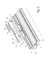
- die Anordnung in einer Explosionsdarstellung
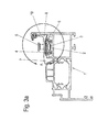
- Figur 3a)
- einen Querschnitt durch die Anordnung nach
Figur 1 - Figur 3b)
- einen vergrößerten Ausschnitt, entsprechend der Kennzeichnung A in
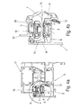
Figur 3a ) - Figur 4a)
- einen Querschnitt durch die Anordnung gemäß der Erfindung bei verriegeltem Flügel
- Figur 4b)
- einen vergrößerten Ausschnitt gemäß der Kennzeichnung A in
Figur 4a ) - Figur 5a)
- den Hinterschnitt nach Figur A in einer Explosionsdarstellung
- Figur 5b)
- den vergrößerten Ausschnitt gemäß der Kennzeichnung B in
Figur 5a ). - In der
Figur 1 ist die Anordnung eines Riegelstangenbeschlags 2 an einem Rahmenholm 1 eines Flügelrahmens eines Fensters oder einer Tür dargestellt, wobei der Riegelstangenbeschlags 2 im Ausführungsbeispiel eine am Rahmenholm 1 gehaltene Riegelstange 3 sowie ein daran befestigtes Schließelement 4 mit einem Schließzapfen 5 aufweist. - Das Schließelement 4, das in der
Figur 2 als Einzelheit zu erkennen ist, ist derart mit der Riegelstange 3 gekoppelt, dass bei deren Betätigung im Sinne einer Längsverschiebung das Schließelement 4 bzw. der Schließzapfen 5 in eine Verriegelungsstellung bzw. aus dieser heraus bewegbar ist, wobei in Verriegelungsstellung der Schließzapfen 5 in ein Riegelstück 16 formschlüssig eingreift, das in einer Haltenut 18 eines blendrahmenseitigen Rahmenholms 17 durch Verschrauben gehalten ist (Figuren 4a) und 4b )). - Gemäß der Erfindung ist das Schließelement 4 von einer formstabilen Leiste 7 überdeckt, die ebenfalls in der
Figur 2 als Einzelheit erkennbar ist und mit dem Rahmenholm 1 fest verbunden ist. - Hierzu sind an einer Längsseite der Leiste 7 Durchgangsbohrungen 11 eingebracht, durch die selbstschneidende Schrauben 12 geführt sind, die, wie besonders deutlich in den
Figuren 4a) und 4b ) zu erkennen ist, schräg in den Rahmenholm 1 eingedreht sind. - Zur vollständigen Anlage der Schrauben 12 in einer Senkung der Durchgangsbohrungen 11 ist der Bereich, in den die Bohrungen 11 eingebracht sind, als Schräge 15 ausgebildet, die etwa im rechten Winkel zur axialen Ausrichtung der Durchgangsbohrungen 11 verläuft. Diese sind im Übrigen durch einen angeformten Steg der Leiste 7 geführt, der sich am Rahmenholm 1 abstützt.
- Die gegenüberliegende Längsseite der Leiste 7 ist als Klemmschenkel 10 ausgebildet, der sich entgegengesetzt zur Ausrichtung des Steges 9 erstreckt und der eine Klemmnut 8 des Rahmenholms 1 hintergreift.
- Zur Montage der Leiste 7 wird diese unter Schrägstellung mit dem Klemmschenkel 10 voran in die Klemmnut 8 eingeführt und anschließend in ihre Endlage verschwenkt, wie sie in vergrößerter Abbildung in der
Figur 3b ) zu erkennen ist. - Die
Figur 2 gibt einen in der Leiste 7 vorgesehenen Durchbruch 13 wieder, der im Sinne eines Langlochs ausgebildet ist, und einen verbreiterten Ausschnitt 14 etwa im Mittenbereich aufweist. - Dieser verbreiterte Ausschnitt 14 ermöglicht das Einsetzen der Leiste 7 mit dem Klemmschenkel 10 voran in die Klemmnut 9, wobei der Ausschnitt 14 in seiner Breite so bemessen ist, dass der Schließzapfen 5 den Ausschnitt 14 durchtreten kann.
- Da der Riegelstangenbeschlag 2 relativ zur Leiste 7 längs verschiebbar ist, ist der Durchbruch 13 in seiner Länge dem Verschiebeweg des Riegelstangenbeschlags 2, d.h. des Schließelementes 4 bzw. des Schließzapfens 5 entsprechend angepasst.
- Die Riegelstange 3 ist im Übrigen in einer Längsnut 6 des Rahmenholms 1 verschieblich gehalten, wobei diese Längsnut 6 Hinterschneidungen aufweist, in die Schenkel der Riegelstange 3 in an sich bekannter Weise eingreifen. Das Schließelement 4 ist verschiebegesichert an der Riegelstange 3 angeschlossen und ebenfalls formschlüssig gesichert.
- Der Riegelstangenbeschlag 2, zu dem neben einem Schließelement 4 auch Eckumlenkungen und mindestens eine Öffnungsschere zählen können, ist zur Realisierung der Einbruchhemmung im Sinne der Erfindung nicht zu verändern, woraus sich eine äußerst günstige Kostensituation ergibt. Dabei kann die Leiste 7 selbstverständlich auch derart eingesetzt werden, dass sie neben dem Schließelement 4 und den Riegelstangen 3 auch gegebenenfalls Eckumlenkungen und Öffnungsscheren derart überdeckt, dass ein gewaltsames Lösen aus ihrer Verankerung verhindert, zumindest jedoch erschwert wird.
-
- 1
- Rahmenholm
- 2
- Riegelstangenbeschlag
- 3
- Riegelstange
- 4
- Schließelement
- 5
- Schließzapfen
- 6
- Längsnut
- 7
- Leiste
- 8
- Klemmnut
- 9
- Steg
- 10
- Klemmschenkel
- 11
- Durchgangsbohrung
- 12
- Schraube
- 13
- Durchbruch
- 14
- Ausschnitt
- 15
- Schräge
- 16
- Riegelstück
- 17
- Rahmenholm
- 18
- Haltenut
Claims (16)
- Anordnung eines Riegelstangenbeschlags (2) an einem Rahmenholm (1) eines Flügelrahmens eines Fensters oder einer Tür, wobei der Riegelstangenbeschlag (2) mindestens eine am Rahmenholm (1) gehaltene Riegelstange (3) sowie wenigstens ein daran befestigtes Schließelement (4) mit einem Schließzapfen (5) aufweist, dadurch gekennzeichnet, dass mit dem Rahmenholm (1) mindestens eine, zumindest einen Teilbereich des Riegelstangenbeschlags (2) wenigstens teilweise überdeckende Leiste (7) fest verbunden ist.
- Anordnung nach Anspruch 1, dadurch gekennzeichnet, dass die Leiste (7) aus einem formstabilen Material besteht.
- Anordnung nach Anspruch 1 oder 2, dadurch gekennzeichnet, dass die Leiste (7) als Abschnitt eines Strangpressprofils, vorzugsweise aus Leichtmetall, ausgebildet ist.
- Anordnung nach einem der vorhergehenden Ansprüche, dadurch gekennzeichnet, dass die Leiste (7) mittels Schrauben (12) am Rahmenholm (1) befestigt ist.
- Anordnung nach einem der vorhergehenden Ansprüche, dadurch gekennzeichnet, dass die Schrauben (12) durch an einer Längsseite der Leiste (7) vorgesehene Durchgangsbohrungen (11) geführt sind.
- Anordnung nach einem der vorhergehenden Ansprüche, dadurch gekennzeichnet, dass die Schrauben (12) schräg in den Rahmenholm (1) eingedreht sind.
- Anordnung nach einem der vorhergehenden Ansprüche, dadurch gekennzeichnet, dass die Leiste (7) auf der den Schrauben (12) gegenüberliegenden Längsseite einen Klemmschenkel (10) aufweist, der in eine hinterschnittene Klemmnut (8) des Rahmenholms (1) eingreift.
- Anordnung nach einem der vorhergehenden Ansprüche, dadurch gekennzeichnet, dass der Klemmschenkel (10) in die der Riegelstange (3) abgewandte Richtung ausgerichtet ist.
- Anordnung nach einem der vorhergehenden Ansprüche, dadurch gekennzeichnet, dass im Querschnitt gesehen entgegengesetzt zur Ausrichtung des Klemmschenkels (10) die Leiste (7) einen angeformten Steg (9) aufweist, durch den die Durchgangsbohrungen (11) geführt sind.
- Anordnung nach einem der vorhergehenden Ansprüche, dadurch gekennzeichnet, dass die Leiste (7) die Riegelstange (3) und/oder das Schließelement (4) und/oder Eckumlenkungen und/oder Öffnungsscheren zumindest teilweise überdeckt.
- Anordnung nach einem der vorhergehenden Ansprüche, dadurch gekennzeichnet, dass die Leiste (7) mit einem Durchbruch (13) versehen ist, der vom Schließzapfen (5) des Schließelementes (4) durchtreten ist.
- Anordnung nach einem der vorhergehenden Ansprüche, dadurch gekennzeichnet, dass der Durchbruch (13) langlochförmig ausgebildet ist, wobei dessen Länge zumindest der Länge eines Verschiebewegs der Riegelstange (3) bzw. des Schließelementes (4) beim Ver- bzw. Entriegeln entspricht.
- Anordnung nach einem der vorhergehenden Ansprüche, dadurch gekennzeichnet, dass der Durchbruch (13) etwa im Mittenbereich einen Ausschnitt (14) aufweist, der breiter ist als die benachbarten Bereiche des Durchbruchs (13).
- Anordnung nach einem der vorhergehenden Ansprüche, dadurch gekennzeichnet, dass die Leiste (7) im Bereich der Durchgangsbohrungen (11) eine sich über die Länge der Leiste (7) erstreckende Schräge (15) aufweist, an der die Schrauben (12) mit ihren Köpfen anliegen.
- Anordnung nach einem der vorhergehenden Ansprüche, dadurch gekennzeichnet, dass die Schräge (15) in ihrer Neigung rechtwinklig zur Ausrichtung der Schrauben (12) verläuft.
- Anordnung nach einem der vorhergehenden Ansprüche, dadurch gekennzeichnet, dass die Schrauben (12) als selbstschneidende Schrauben ausgebildet sind.
Applications Claiming Priority (1)
| Application Number | Priority Date | Filing Date | Title |
|---|---|---|---|
| DE202013104981U DE202013104981U1 (de) | 2013-11-06 | 2013-11-06 | Anordnung eines Riegelstangenbeschlags an einem Rahmenholm |
Publications (3)
| Publication Number | Publication Date |
|---|---|
| EP2871306A2 true EP2871306A2 (de) | 2015-05-13 |
| EP2871306A3 EP2871306A3 (de) | 2016-01-20 |
| EP2871306B1 EP2871306B1 (de) | 2018-08-08 |
Family
ID=49944395
Family Applications (1)
| Application Number | Title | Priority Date | Filing Date |
|---|---|---|---|
| EP14191845.8A Active EP2871306B1 (de) | 2013-11-06 | 2014-11-05 | Anordnung mit einem Riegelstangenbeschlag an einem Rahmenholm |
Country Status (2)
| Country | Link |
|---|---|
| EP (1) | EP2871306B1 (de) |
| DE (1) | DE202013104981U1 (de) |
Cited By (1)
| Publication number | Priority date | Publication date | Assignee | Title |
|---|---|---|---|---|
| EP4517030A1 (de) * | 2023-08-29 | 2025-03-05 | Aug. Winkhaus SE & Co. KG | Verschluss für einen treibstangenbeschlag |
Families Citing this family (2)
| Publication number | Priority date | Publication date | Assignee | Title |
|---|---|---|---|---|
| DE102017100335A1 (de) | 2016-02-29 | 2017-08-31 | SCHÜCO International KG | Tür, Fenster oder Fassadenelement sowie Beschlaganordnung für ein solches Element |
| CN110792361A (zh) * | 2018-08-02 | 2020-02-14 | 深圳市派阁智能五金科技有限公司 | 一种型材与五金配件的安装结构 |
Citations (3)
| Publication number | Priority date | Publication date | Assignee | Title |
|---|---|---|---|---|
| EP1867822A2 (de) | 2006-06-15 | 2007-12-19 | SAVIO S.p.A. | Tür- und Fensterrahmen mit einem hinterschnittenen Eingriffsbereich für eine Getriebeeinheit |
| EP2423426A1 (de) | 2010-08-31 | 2012-02-29 | Sälzer Sicherheitstechnik GmbH | Einbruchhemmender und/oder sprengwirkungshemmender Gebäudeabschluss |
| DE102013100310A1 (de) | 2013-01-11 | 2014-07-17 | SCHÜCO International KG | Riegelstange für einen Riegelstangenbeschlag |
Family Cites Families (2)
| Publication number | Priority date | Publication date | Assignee | Title |
|---|---|---|---|---|
| DE2238862C3 (de) * | 1972-08-07 | 1982-04-08 | Götz Metallbau GmbH, 8360 Deggendorf | Führungsbahn in Flügelrahmen aus Metall mit einem zur Beschlagbetätigung dienenden, flexiblen Metallband |
| BE1012234A3 (nl) * | 1998-10-16 | 2000-07-04 | Parys Remi E Van | Op een schuifpaneelconstructie gemonteerde sluiting en sluitplaat daarvoor. |
-
2013
- 2013-11-06 DE DE202013104981U patent/DE202013104981U1/de not_active Expired - Lifetime
-
2014
- 2014-11-05 EP EP14191845.8A patent/EP2871306B1/de active Active
Patent Citations (3)
| Publication number | Priority date | Publication date | Assignee | Title |
|---|---|---|---|---|
| EP1867822A2 (de) | 2006-06-15 | 2007-12-19 | SAVIO S.p.A. | Tür- und Fensterrahmen mit einem hinterschnittenen Eingriffsbereich für eine Getriebeeinheit |
| EP2423426A1 (de) | 2010-08-31 | 2012-02-29 | Sälzer Sicherheitstechnik GmbH | Einbruchhemmender und/oder sprengwirkungshemmender Gebäudeabschluss |
| DE102013100310A1 (de) | 2013-01-11 | 2014-07-17 | SCHÜCO International KG | Riegelstange für einen Riegelstangenbeschlag |
Cited By (1)
| Publication number | Priority date | Publication date | Assignee | Title |
|---|---|---|---|---|
| EP4517030A1 (de) * | 2023-08-29 | 2025-03-05 | Aug. Winkhaus SE & Co. KG | Verschluss für einen treibstangenbeschlag |
Also Published As
| Publication number | Publication date |
|---|---|
| EP2871306A3 (de) | 2016-01-20 |
| DE202013104981U1 (de) | 2013-12-12 |
| EP2871306B1 (de) | 2018-08-08 |
Similar Documents
| Publication | Publication Date | Title |
|---|---|---|
| DE69612273T2 (de) | Mehrpunkt-Verriegelungsstruktur für einen Verschlussmechanismus mit Gleitschiene | |
| EP1500351B1 (de) | Befestigungsvorrichtung für Schubladenfrontblenden | |
| EP2871306B1 (de) | Anordnung mit einem Riegelstangenbeschlag an einem Rahmenholm | |
| DE102009031035B4 (de) | Einbruchsicherung | |
| EP2754805A2 (de) | Riegelstange für einen Riegelstangenbeschlag | |
| EP3112577B1 (de) | Absenkdichtung | |
| EP3450674B1 (de) | Rollladen | |
| DE8913826U1 (de) | Verriegelungsvorrichtung für ein Fenster, eine Tür o.dgl. | |
| DE19521601C1 (de) | Fenster, Tür oder dergleichen | |
| EP2708693B1 (de) | Schiebeflügelrahmen | |
| EP2589739B1 (de) | Beschlag | |
| EP2385200B1 (de) | Beschlagteil zur Befestigung an einer C-förmigen Beschlagteilnut | |
| EP2754803A2 (de) | Riegelstangenbeschlag für ein Fenster oder eine Tür | |
| EP3516135B1 (de) | Beschlag | |
| DE202015100200U1 (de) | Bandlappenanordnung eines Bandes | |
| DE19752619A1 (de) | Verbindungsbauteil für eine Fassadenkonstruktion und Fassadenkonstruktion | |
| EP1970513B1 (de) | Standflügel und Standflügelverschluss | |
| EP1983138A2 (de) | Gebäudeelement mit einem im Rahmen dichtend gehaltenen Ausfachungselement | |
| EP3121356B1 (de) | Anordnung eines scharniers an einem hohlkammerprofil | |
| CH656915A5 (de) | Vorrichtung zur kupplung senkrecht zueinander verlaufender treibstangen. | |
| EP3816383A1 (de) | Schiebetüranordnung | |
| EP1493889A1 (de) | Schliessplatte | |
| EP2754802A2 (de) | Riegelstangenbeschlag für ein Fenster oder eine Tür | |
| EP2787160B1 (de) | Dichtung für einen Riegel und Dichtungsanordnung mit einer solchen Dichtung | |
| DE3001025A1 (de) | Vorrichtung zur befestigung eines beschlages in einem fluegelprofil fuer fenster oder tueren |
Legal Events
| Date | Code | Title | Description |
|---|---|---|---|
| PUAI | Public reference made under article 153(3) epc to a published international application that has entered the european phase |
Free format text: ORIGINAL CODE: 0009012 |
|
| 17P | Request for examination filed |
Effective date: 20141105 |
|
| AK | Designated contracting states |
Kind code of ref document: A2 Designated state(s): AL AT BE BG CH CY CZ DE DK EE ES FI FR GB GR HR HU IE IS IT LI LT LU LV MC MK MT NL NO PL PT RO RS SE SI SK SM TR |
|
| AX | Request for extension of the european patent |
Extension state: BA ME |
|
| PUAL | Search report despatched |
Free format text: ORIGINAL CODE: 0009013 |
|
| AK | Designated contracting states |
Kind code of ref document: A3 Designated state(s): AL AT BE BG CH CY CZ DE DK EE ES FI FR GB GR HR HU IE IS IT LI LT LU LV MC MK MT NL NO PL PT RO RS SE SI SK SM TR |
|
| AX | Request for extension of the european patent |
Extension state: BA ME |
|
| RIC1 | Information provided on ipc code assigned before grant |
Ipc: E05C 9/18 20060101ALI20151215BHEP Ipc: E05B 17/20 20060101AFI20151215BHEP |
|
| R17P | Request for examination filed (corrected) |
Effective date: 20160713 |
|
| RBV | Designated contracting states (corrected) |
Designated state(s): AL AT BE BG CH CY CZ DE DK EE ES FI FR GB GR HR HU IE IS IT LI LT LU LV MC MK MT NL NO PL PT RO RS SE SI SK SM TR |
|
| 17Q | First examination report despatched |
Effective date: 20170410 |
|
| GRAP | Despatch of communication of intention to grant a patent |
Free format text: ORIGINAL CODE: EPIDOSNIGR1 |
|
| INTG | Intention to grant announced |
Effective date: 20180329 |
|
| GRAS | Grant fee paid |
Free format text: ORIGINAL CODE: EPIDOSNIGR3 |
|
| GRAA | (expected) grant |
Free format text: ORIGINAL CODE: 0009210 |
|
| AK | Designated contracting states |
Kind code of ref document: B1 Designated state(s): AL AT BE BG CH CY CZ DE DK EE ES FI FR GB GR HR HU IE IS IT LI LT LU LV MC MK MT NL NO PL PT RO RS SE SI SK SM TR |
|
| REG | Reference to a national code |
Ref country code: GB Ref legal event code: FG4D Free format text: NOT ENGLISH |
|
| REG | Reference to a national code |
Ref country code: CH Ref legal event code: EP Ref country code: AT Ref legal event code: REF Ref document number: 1027201 Country of ref document: AT Kind code of ref document: T Effective date: 20180815 |
|
| REG | Reference to a national code |
Ref country code: CH Ref legal event code: NV Representative=s name: KATZAROV SA, CH |
|
| REG | Reference to a national code |
Ref country code: IE Ref legal event code: FG4D Free format text: LANGUAGE OF EP DOCUMENT: GERMAN |
|
| REG | Reference to a national code |
Ref country code: DE Ref legal event code: R096 Ref document number: 502014009120 Country of ref document: DE |
|
| REG | Reference to a national code |
Ref country code: NL Ref legal event code: MP Effective date: 20180808 |
|
| REG | Reference to a national code |
Ref country code: LT Ref legal event code: MG4D |
|
| PG25 | Lapsed in a contracting state [announced via postgrant information from national office to epo] |
Ref country code: BG Free format text: LAPSE BECAUSE OF FAILURE TO SUBMIT A TRANSLATION OF THE DESCRIPTION OR TO PAY THE FEE WITHIN THE PRESCRIBED TIME-LIMIT Effective date: 20181108 Ref country code: SE Free format text: LAPSE BECAUSE OF FAILURE TO SUBMIT A TRANSLATION OF THE DESCRIPTION OR TO PAY THE FEE WITHIN THE PRESCRIBED TIME-LIMIT Effective date: 20180808 Ref country code: NL Free format text: LAPSE BECAUSE OF FAILURE TO SUBMIT A TRANSLATION OF THE DESCRIPTION OR TO PAY THE FEE WITHIN THE PRESCRIBED TIME-LIMIT Effective date: 20180808 Ref country code: PL Free format text: LAPSE BECAUSE OF FAILURE TO SUBMIT A TRANSLATION OF THE DESCRIPTION OR TO PAY THE FEE WITHIN THE PRESCRIBED TIME-LIMIT Effective date: 20180808 Ref country code: FI Free format text: LAPSE BECAUSE OF FAILURE TO SUBMIT A TRANSLATION OF THE DESCRIPTION OR TO PAY THE FEE WITHIN THE PRESCRIBED TIME-LIMIT Effective date: 20180808 Ref country code: LT Free format text: LAPSE BECAUSE OF FAILURE TO SUBMIT A TRANSLATION OF THE DESCRIPTION OR TO PAY THE FEE WITHIN THE PRESCRIBED TIME-LIMIT Effective date: 20180808 Ref country code: RS Free format text: LAPSE BECAUSE OF FAILURE TO SUBMIT A TRANSLATION OF THE DESCRIPTION OR TO PAY THE FEE WITHIN THE PRESCRIBED TIME-LIMIT Effective date: 20180808 Ref country code: GR Free format text: LAPSE BECAUSE OF FAILURE TO SUBMIT A TRANSLATION OF THE DESCRIPTION OR TO PAY THE FEE WITHIN THE PRESCRIBED TIME-LIMIT Effective date: 20181109 Ref country code: IS Free format text: LAPSE BECAUSE OF FAILURE TO SUBMIT A TRANSLATION OF THE DESCRIPTION OR TO PAY THE FEE WITHIN THE PRESCRIBED TIME-LIMIT Effective date: 20181208 Ref country code: NO Free format text: LAPSE BECAUSE OF FAILURE TO SUBMIT A TRANSLATION OF THE DESCRIPTION OR TO PAY THE FEE WITHIN THE PRESCRIBED TIME-LIMIT Effective date: 20181108 |
|
| PG25 | Lapsed in a contracting state [announced via postgrant information from national office to epo] |
Ref country code: AL Free format text: LAPSE BECAUSE OF FAILURE TO SUBMIT A TRANSLATION OF THE DESCRIPTION OR TO PAY THE FEE WITHIN THE PRESCRIBED TIME-LIMIT Effective date: 20180808 Ref country code: HR Free format text: LAPSE BECAUSE OF FAILURE TO SUBMIT A TRANSLATION OF THE DESCRIPTION OR TO PAY THE FEE WITHIN THE PRESCRIBED TIME-LIMIT Effective date: 20180808 Ref country code: LV Free format text: LAPSE BECAUSE OF FAILURE TO SUBMIT A TRANSLATION OF THE DESCRIPTION OR TO PAY THE FEE WITHIN THE PRESCRIBED TIME-LIMIT Effective date: 20180808 |
|
| PG25 | Lapsed in a contracting state [announced via postgrant information from national office to epo] |
Ref country code: IT Free format text: LAPSE BECAUSE OF FAILURE TO SUBMIT A TRANSLATION OF THE DESCRIPTION OR TO PAY THE FEE WITHIN THE PRESCRIBED TIME-LIMIT Effective date: 20180808 Ref country code: EE Free format text: LAPSE BECAUSE OF FAILURE TO SUBMIT A TRANSLATION OF THE DESCRIPTION OR TO PAY THE FEE WITHIN THE PRESCRIBED TIME-LIMIT Effective date: 20180808 Ref country code: RO Free format text: LAPSE BECAUSE OF FAILURE TO SUBMIT A TRANSLATION OF THE DESCRIPTION OR TO PAY THE FEE WITHIN THE PRESCRIBED TIME-LIMIT Effective date: 20180808 Ref country code: CZ Free format text: LAPSE BECAUSE OF FAILURE TO SUBMIT A TRANSLATION OF THE DESCRIPTION OR TO PAY THE FEE WITHIN THE PRESCRIBED TIME-LIMIT Effective date: 20180808 Ref country code: ES Free format text: LAPSE BECAUSE OF FAILURE TO SUBMIT A TRANSLATION OF THE DESCRIPTION OR TO PAY THE FEE WITHIN THE PRESCRIBED TIME-LIMIT Effective date: 20180808 |
|
| REG | Reference to a national code |
Ref country code: DE Ref legal event code: R097 Ref document number: 502014009120 Country of ref document: DE |
|
| PG25 | Lapsed in a contracting state [announced via postgrant information from national office to epo] |
Ref country code: SK Free format text: LAPSE BECAUSE OF FAILURE TO SUBMIT A TRANSLATION OF THE DESCRIPTION OR TO PAY THE FEE WITHIN THE PRESCRIBED TIME-LIMIT Effective date: 20180808 Ref country code: DK Free format text: LAPSE BECAUSE OF FAILURE TO SUBMIT A TRANSLATION OF THE DESCRIPTION OR TO PAY THE FEE WITHIN THE PRESCRIBED TIME-LIMIT Effective date: 20180808 Ref country code: SM Free format text: LAPSE BECAUSE OF FAILURE TO SUBMIT A TRANSLATION OF THE DESCRIPTION OR TO PAY THE FEE WITHIN THE PRESCRIBED TIME-LIMIT Effective date: 20180808 |
|
| PLBE | No opposition filed within time limit |
Free format text: ORIGINAL CODE: 0009261 |
|
| STAA | Information on the status of an ep patent application or granted ep patent |
Free format text: STATUS: NO OPPOSITION FILED WITHIN TIME LIMIT |
|
| 26N | No opposition filed |
Effective date: 20190509 |
|
| GBPC | Gb: european patent ceased through non-payment of renewal fee |
Effective date: 20181108 |
|
| PG25 | Lapsed in a contracting state [announced via postgrant information from national office to epo] |
Ref country code: MC Free format text: LAPSE BECAUSE OF FAILURE TO SUBMIT A TRANSLATION OF THE DESCRIPTION OR TO PAY THE FEE WITHIN THE PRESCRIBED TIME-LIMIT Effective date: 20180808 Ref country code: LU Free format text: LAPSE BECAUSE OF NON-PAYMENT OF DUE FEES Effective date: 20181105 |
|
| REG | Reference to a national code |
Ref country code: BE Ref legal event code: MM Effective date: 20181130 |
|
| REG | Reference to a national code |
Ref country code: IE Ref legal event code: MM4A |
|
| PG25 | Lapsed in a contracting state [announced via postgrant information from national office to epo] |
Ref country code: SI Free format text: LAPSE BECAUSE OF FAILURE TO SUBMIT A TRANSLATION OF THE DESCRIPTION OR TO PAY THE FEE WITHIN THE PRESCRIBED TIME-LIMIT Effective date: 20180808 |
|
| PG25 | Lapsed in a contracting state [announced via postgrant information from national office to epo] |
Ref country code: FR Free format text: LAPSE BECAUSE OF NON-PAYMENT OF DUE FEES Effective date: 20181130 Ref country code: IE Free format text: LAPSE BECAUSE OF NON-PAYMENT OF DUE FEES Effective date: 20181105 |
|
| PG25 | Lapsed in a contracting state [announced via postgrant information from national office to epo] |
Ref country code: BE Free format text: LAPSE BECAUSE OF NON-PAYMENT OF DUE FEES Effective date: 20181130 |
|
| PG25 | Lapsed in a contracting state [announced via postgrant information from national office to epo] |
Ref country code: GB Free format text: LAPSE BECAUSE OF NON-PAYMENT OF DUE FEES Effective date: 20181108 |
|
| PG25 | Lapsed in a contracting state [announced via postgrant information from national office to epo] |
Ref country code: MT Free format text: LAPSE BECAUSE OF FAILURE TO SUBMIT A TRANSLATION OF THE DESCRIPTION OR TO PAY THE FEE WITHIN THE PRESCRIBED TIME-LIMIT Effective date: 20180808 |
|
| PG25 | Lapsed in a contracting state [announced via postgrant information from national office to epo] |
Ref country code: TR Free format text: LAPSE BECAUSE OF FAILURE TO SUBMIT A TRANSLATION OF THE DESCRIPTION OR TO PAY THE FEE WITHIN THE PRESCRIBED TIME-LIMIT Effective date: 20180808 |
|
| PG25 | Lapsed in a contracting state [announced via postgrant information from national office to epo] |
Ref country code: PT Free format text: LAPSE BECAUSE OF FAILURE TO SUBMIT A TRANSLATION OF THE DESCRIPTION OR TO PAY THE FEE WITHIN THE PRESCRIBED TIME-LIMIT Effective date: 20180808 |
|
| PG25 | Lapsed in a contracting state [announced via postgrant information from national office to epo] |
Ref country code: CY Free format text: LAPSE BECAUSE OF FAILURE TO SUBMIT A TRANSLATION OF THE DESCRIPTION OR TO PAY THE FEE WITHIN THE PRESCRIBED TIME-LIMIT Effective date: 20180808 Ref country code: HU Free format text: LAPSE BECAUSE OF FAILURE TO SUBMIT A TRANSLATION OF THE DESCRIPTION OR TO PAY THE FEE WITHIN THE PRESCRIBED TIME-LIMIT; INVALID AB INITIO Effective date: 20141105 Ref country code: MK Free format text: LAPSE BECAUSE OF NON-PAYMENT OF DUE FEES Effective date: 20180808 |
|
| P01 | Opt-out of the competence of the unified patent court (upc) registered |
Effective date: 20230814 |
|
| REG | Reference to a national code |
Ref country code: CH Ref legal event code: U11 Free format text: ST27 STATUS EVENT CODE: U-0-0-U10-U11 (AS PROVIDED BY THE NATIONAL OFFICE) Effective date: 20251201 |
|
| PGFP | Annual fee paid to national office [announced via postgrant information from national office to epo] |
Ref country code: DE Payment date: 20251020 Year of fee payment: 12 |
|
| PGFP | Annual fee paid to national office [announced via postgrant information from national office to epo] |
Ref country code: AT Payment date: 20251104 Year of fee payment: 12 |
|
| PGFP | Annual fee paid to national office [announced via postgrant information from national office to epo] |
Ref country code: CH Payment date: 20251201 Year of fee payment: 12 |