EP2868837A1 - Abstandselement - Google Patents
Abstandselement Download PDFInfo
- Publication number
- EP2868837A1 EP2868837A1 EP20140187480 EP14187480A EP2868837A1 EP 2868837 A1 EP2868837 A1 EP 2868837A1 EP 20140187480 EP20140187480 EP 20140187480 EP 14187480 A EP14187480 A EP 14187480A EP 2868837 A1 EP2868837 A1 EP 2868837A1
- Authority
- EP
- European Patent Office
- Prior art keywords
- blocks
- spacer element
- element according
- strands
- spacer
- Prior art date
- Legal status (The legal status is an assumption and is not a legal conclusion. Google has not performed a legal analysis and makes no representation as to the accuracy of the status listed.)
- Granted
Links
Images


Classifications
-
- E—FIXED CONSTRUCTIONS
- E04—BUILDING
- E04F—FINISHING WORK ON BUILDINGS, e.g. STAIRS, FLOORS
- E04F15/00—Flooring
- E04F15/02—Flooring or floor layers composed of a number of similar elements
-
- E—FIXED CONSTRUCTIONS
- E01—CONSTRUCTION OF ROADS, RAILWAYS, OR BRIDGES
- E01C—CONSTRUCTION OF, OR SURFACES FOR, ROADS, SPORTS GROUNDS, OR THE LIKE; MACHINES OR AUXILIARY TOOLS FOR CONSTRUCTION OR REPAIR
- E01C5/00—Pavings made of prefabricated single units
- E01C5/005—Individual couplings or spacer elements for joining the prefabricated units
- E01C5/006—Individual spacer elements
-
- E—FIXED CONSTRUCTIONS
- E04—BUILDING
- E04F—FINISHING WORK ON BUILDINGS, e.g. STAIRS, FLOORS
- E04F15/00—Flooring
- E04F15/02—Flooring or floor layers composed of a number of similar elements
- E04F15/04—Flooring or floor layers composed of a number of similar elements only of wood or with a top layer of wood, e.g. with wooden or metal connecting members
-
- E—FIXED CONSTRUCTIONS
- E04—BUILDING
- E04F—FINISHING WORK ON BUILDINGS, e.g. STAIRS, FLOORS
- E04F2201/00—Joining sheets or plates or panels
- E04F2201/05—Separate connectors or inserts, e.g. pegs, pins, keys or strips
- E04F2201/0511—Strips or bars, e.g. nailing strips
Definitions
- the invention relates to a spacer element for the arrangement between two components which are to be arranged or mounted at a distance.
- spacer strip for terrace construction. It is made of plastic and has a wavy meandering shape.
- the spacer strip has a continuous constant height and is screwed with screws on a bar forming the base.
- the invention is based on the object to provide a spacer which is flexible in use and in particular allows a suitable water drainage and air circulation.
- the invention proposes a spacer element with the features mentioned in claim 1. Further developments of the invention are the subject of dependent claims.
- the spacing element thus contains, to form the distance, the plurality of blocks of the same height, the height of which thus defines the distance.
- Under height is to be understood as the extension between the two support or end faces of the blocks, while the web connects the sides of the blocks together.
- the end faces of the blocks are to be arranged in each case a common plane to all blocks. In other words, therefore, when resting on a flat surface, both the upper end faces of all blocks are aligned with each other and the lower end faces of all blocks should be aligned. Due to the elasticity of the webs, the two bearing or end surfaces but also in each case a surface, for example, a circular cylindrical surface, be arranged, wherein on the surface then all upper or all lower end faces of the blocks are.
- the blocks are arranged in strands at a mutual distance and two successive blocks are each connected by a web.
- the web can serve not only to save material, but also to elastically design each strand laterally without reducing the stability of the strand in the loading direction, which is determined by the stability of the blocks, thereby.
- connection points sections may be formed in particular identical.
- the width of the spacer element is variable perpendicular to the laying direction, for example by deforming the spacer element. This should make it possible to adapt the spacer to different widths substructures. For example, if the substructure is constructed of battens with a mutual distance, it should be possible to arrange the spacer so that it bridges the slats.
- a section has two strands of blocks, wherein the end faces of the blocks of the one strand lie in each case in the same plane as the end faces of the blocks of the other strand.
- both strands of a section may meet at the same junction at the respective ends of the section.
- the two strands of blocks of a section towards each other in the direction of the junction approach if necessary meet there.
- the remaining area ie in the area between the joints of the sections, they have a greater distance. For example, the distance in the middle between two joints may be greatest.
- both strands of the spacer element are rectilinear and run parallel to one another.
- the sections of the spacer element, as far as the strands are concerned can merge directly into one another.
- the two strands can still be connected to each other or connectable to each other.
- the web connecting the blocks serves to save material and to make the respective strand more flexible, and in particular is narrow for this purpose. Its main purpose is to connect the blocks to form a unit that can be handled in a uniform manner.
- the height of the web connecting the blocks is smaller than the height of the blocks.
- the web has a distance from the planes of both end faces of the blocks. It is then no longer possible to enable the water permeability to the orientation of the spacer.
- connection point can be formed in a further embodiment of the invention such that it has a connection node, which is common to both adjacent sections.
- the two strands in particular when they are parallel to each other, are connected by a transverse web, so that the connection point both for connection of the portions of the spacer element as well as for connection the two strands of a section is used.
- This crossbar may in particular be connected in a hinge-like manner with one block of each strand. Then, a change in the distance between the two strands and thus the width of the spacer element can be achieved by pivoting the cross bar. Also possible is the deformation of the crosspiece in itself.
- connection point is smaller than the height of the blocks.
- an end face of the connection point is aligned with the plane of the one end face of the blocks of both adjacent sections.
- connection point has a through hole which runs parallel to the direction of the height of the blocks.
- the joint can therefore be used, for example, to set the spacer to the pad with a nail or a screw.
- the spacer element is modularly constructed from a plurality of sections, it may be necessary to shorten a spacer element.
- the spacer element has weak points at which one can separate the spacer element. It makes sense to have the weak points around the joints, but it is also possible to arrange these alternatively or additionally between adjacent blocks.
- the spacer By using weak points, it is advisable to produce the spacer in relatively long lengths, so that it can also be rolled up and stored as a profile material.
- At least one strand has two rectilinear parts or sections which enclose an angle between them.
- At least one strand is bent.
- the arrangement of the strands is formed symmetrically to a line connecting the connection points of a section.
- the invention proposes to produce the spacer from a biodegradable plastic.
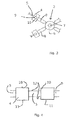
- FIG. 1 shows a spacer element, which is composed of three substantially identical sections 1.
- Each section 1 extends between two connection points 2, wherein the outer sections terminate at a connection point 2.
- a spacer element is made up of a much larger number of sections 1, but for presentation, three sections 1 are sufficient.
- Each section 1 has two strands 3 of spacer blocks 4, which are connected by a continuous web 5 with each other and with the connection points 2.
- each strand 3 of spacer blocks 4 has two rectilinear sections 3a, 3b which enclose an obtuse angle with each other.
- the web 5 is much narrower than the spacer blocks 4. In its respective last section between the last spacer block 4 and the Joint 2, the web 5 is formed wider and has the transition to the actual joint 2 a decreasing width, which ends in a point.
- the spacer element has a longitudinal direction which coincides with a connecting line between the connection points 2 of a section 1. With regard to this longitudinal direction, the two strands 3 are formed and arranged symmetrically. Approximately in the middle between the two connection points 2, the two strands 3 have their greatest mutual distance.
- connection point 2 is designed as an annular connection node 6, which has a central hole 7.
- the end portions 8 of both webs 5 have over the remaining part of the webs 5 a greater width.
- its width decreases almost to a peak.
- a weak point is formed directly on the circumference of the connection node 6, at which it is easy to tear off the webs 5 from the connection point 2.
- Each spacer block 4 has a hole 9, which passes from the one end face 10 of each spacer block 4 to the opposite end face.
- FIG. 2 the spacer element from the lateral direction of the FIG. 1 represents, and the line of sight in Fig. 2 so obliquely meets the webs 5, shows the FIG. 4 on an enlarged scale a side view of two spacer blocks in a direction perpendicular to the course of the web 5.
- Each block 4 has two mutually parallel opposite end faces 10, 11. The distance between the two end faces 10, 11 from each other forms the height of the spacer block 4.
- the in FIG. 4 upper end surfaces 10 of all spacer blocks of both strands 3 of a section lie in one plane, as well as the lower end faces 11 in FIG. 4 of all spacer blocks 4 of both strands 3.
- the web 5 connecting the spacer blocks 4 is not only, as has already been pointed out, narrower than the spacer blocks 4, but also has a smaller height. Both longitudinal edges 12 of the web 5 have a distance from the planes in which the respective end faces 10 and 11 of the spacer blocks 4 are located. As a result, when the spacer blocks are arranged between two elements to be mounted at a distance, the water can flow below and optionally also above the web 5.
- the hole 7 in the connection node 6 can serve to fix the spacer by means of a nail or a screw on the pad.
- the spacer blocks 4 are cuboid with a rectangular plan educated.
- the spacer blocks have other basic shapes, for example a cube shape.
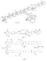
- FIGS. 5 to 7 show a second embodiment of the invention proposed by the spacer element.
- the same reference numerals are used for the same elements of this spacer.
- FIG. 7 corresponding plan view of a portion 1 of the second embodiment of the spacer shows.
- the section 1 in turn consists of two strands 3 of a mutual distance blocks 4 of the same height.
- the blocks 4 are connected to each other by respective sections of a web 5.
- the two strands 3 of blocks 4 each extend in a straight line and parallel to one another. They are connected by the junction 2 forming transverse webs 13 with each other. These transverse webs 13 are in FIG. 7 shown canceled.
- the webs 5 between the blocks 4 have the same width as this.
- the two strands 3 connecting transverse webs 13 is significantly narrower than the strands 3, since it should be deformed. For example, if you have the in FIG. 7 moves lower strand 3 in its own longitudinal direction, approach the two strands 3 due to the parallelogram effect of the transverse webs 13 to each other. This can be done both by the fact that the transverse webs 13 remain in a straight line to pivot at their points of application, as well as by deforming themselves in an S-shape. In this way, the distance between the two strands 3 of spacer blocks 4 can be changed. From the side view of FIG. 6 , from below in FIG.
- the web 5 is formed in the height direction approximately in the middle between the two end faces 10, 11 of the blocks 4, so that both above and below the webs 5 remains a gap through which water can flow.
- the web 5 is offset downwards in the height direction, so that its underside 14 lies here at a height with the underside of the individual blocks 4.
- the web 5 ' is slightly longer than between the other blocks 4.
- the web has at this point an opening 19 for the insertion of a screw or a nail.
- This arrangement has over the arrangement of the hole 9 in the blocks 4 has the advantage that a screw head 4 at this point does not protrude beyond the upper end face 10 of the blocks 4 and therefore does not bother.
- FIG. 5 shows a section of a spacer in a broken representation. It can be seen that the transverse web 13 is also narrower in the height direction than the blocks 4.
- the width of the spacer i. in this case, the distance between the outer side of the strands 3, which faces away from the respective other strand, can be changed.
- the maximum distance is determined by the length of the transverse webs 13. To reduce the distance, the two strands 3 are moved approximately parallel to one another.
- the width of the spacer may be changed by approximating two joints 2, thereby pushing the kinks of the two strands 3 outward.
- the width of the spacer can be changed individually for each section.
- the spacer element of both embodiments is produced in one piece as an injection-molded part, for example in lengths of 0.5 m.
- the number and arrangement of the blocks in each section can be chosen arbitrarily.
Landscapes
- Engineering & Computer Science (AREA)
- Architecture (AREA)
- Civil Engineering (AREA)
- Structural Engineering (AREA)
- Life Sciences & Earth Sciences (AREA)
- Wood Science & Technology (AREA)
- Prostheses (AREA)
- Bridges Or Land Bridges (AREA)
- Fuel Cell (AREA)
Abstract
Description
- Die Erfindung betrifft ein Abstandselement zur Anordnung zwischen zwei Bauteilen, die auf Abstand angeordnet oder montiert werden sollen.
- Es ist bereits eine Distanzleiste für den Terrassenbau bekannt. Sie besteht aus Kunststoff und ist mäanderförmig gewellt. Die Distanzleiste hat eine durchgehende konstante Höhe und wird mit Schrauben an einer die Unterlage bildenden Leiste angeschraubt.
- Der Erfindung liegt die Aufgabe zu Grunde, ein Abstandselement zu schaffen, das flexibel einsetzbar ist und insbesondere einen geeigneten Wasserabfluss und eine Luftzirkulation ermöglicht.
- Zur Lösung dieser Aufgabe schlägt die Erfindung ein Abstandselement mit den im Anspruch 1 genannten Merkmalen vor. Weiterbildungen der Erfindung sind Gegenstand von Unteransprüchen.
- Das Abstandselement enthält also zur Bildung des Abstands die Vielzahl von Blöcken gleicher Höhe, deren Höhe damit den Abstand definiert. Unter Höhe ist dabei die Erstreckung zwischen den beiden Auflage- beziehungsweise Stirnflächen der Blöcke zu verstehen, während der Steg die Seiten der Blöcke miteinander verbindet. Die Stirnflächen der Blöcke, sind in jeweils einer allen Blöcken gemeinsamen Ebene anzuordnen. Mit anderen Worten sollen also bei Auflage auf einer ebenen Fläche sowohl die oberen Stirnflächen aller Blöcke zueinander fluchten und auch die unteren Stirnseiten aller Blöcke sollen zueinander fluchten. Aufgrund der Elastität der Stege können die beiden Auflage- beziehungsweise Stirnflächen aber auch in jeweils einer Fläche, beispielsweise eines Kreiszylinderfläche, angeordnet sein, wobei auf der Fläche dann alle oberen beziehungsweise alle unteren Stirnflächen der Blöcke liegen. Die Blöcke sind in Strängen im gegenseitigen Abstand angeordnet und zwei aufeinander folgende Blöcke sind jeweils durch einen Steg miteinander verbunden.
- Der Steg kann nicht nur dazu dienen, Material zu sparen, sondern auch, jeden Strang in seitlicher Richtung elastisch auszugestalten, ohne dass die Stabilität des Strangs in Belastungsrichtung, die durch die Stabilität der Blöcke bestimmt ist, dadurch verringert wird.
- Die einzelnen an den Verbindungsstellen paarweise miteinander verbundenen Abschnitte können insbesondere identisch ausgebildet sein.
- In Weiterbildung der Erfindung kann vorgesehen sein, dass die Breite des Abstandselements senkrecht zur Verlegerichtung veränderbar ist, beispielsweise durch ein Verformen des Abstandselements. Dadurch soll es ermöglicht werden, das Abstandselement an unterschiedlich breite Unterkonstruktionen anzupassen. Wenn beispielsweise die Unterkonstruktion aus Latten mit einem gegenseitigen Abstand aufgebaut ist, soll es möglich sein, das Abstandselement so anzuordnen, dass es die Latten überbrückt.
- In Weiterbildung der Erfindung kann vorgesehen sein, dass ein Abschnitt zwei Stränge von Blöcken aufweist, wobei die Stirnflächen der Blöcke des einen Strangs in jeweils der gleichen Ebene liegen wie die Stirnflächen der Blöcke des anderen Strangs.
- Beide Stränge eines Abschnitts können sich beispielsweise in der gleichen Verbindungsstelle an den jeweiligen Enden des Abschnitts treffen.
- Es kann in Weiterbildung vorgesehen sein, dass die beiden Stränge von Blöcken eines Abschnitts sich in Richtung auf die Verbindungsstelle einander annähern, gegebenenfalls sich dort auch treffen. Im übrigen Bereich, d. h. im Bereich zwischen den Verbindungsstellen der Abschnitte, weisen sie dagegen einen größeren Abstand auf. Beispielsweise kann der Abstand in der Mitte zwischen zwei Verbindungsstellen am größten sein.
- Es ist ebenfalls möglich und liegt im Rahmen der Erfindung, dass beide Stränge des Abstandselement geradlinig ausgebildet sind und parallel zueinander verlaufen. In diesem Fall können die Abschnitte des Abstandselements, was die Stränge angeht, unmittelbar ineinander übergehen. An der Verbindungsstelle können die beiden Stränge dennoch miteinander verbunden oder miteinander verbindbar sein.
- Es wurde bereits erwähnt, dass der die Blöcke verbindende Steg zur Materialersparnis und zur Flexibilisierung des jeweiligen Strangs dient und zu diesem Zweck insbesondere schmal ist. Er dient in erster Linie dazu, die Blöcke zu einem einheitlich handhabbaren Element zu verbinden.
- In Weiterbildung kann vorgesehen sein, dass auch die Höhe des die Blöcke verbindenden Stegs kleiner ist als die Höhe der Blöcke. Damit wird dann auch die Wasserdurchlässigkeit und die Luftzirkulation verbessert, da das Wasser an dem Steg vorbei fließen kann.
- Insbesondere kann vorgesehen sein, dass der Steg von den Ebenen beider Stirnflächen der Blöcke einen Abstand aufweist. Es kommt dann zur Ermöglichung der Wasserdurchlässigkeit nicht mehr auf die Orientierung des Abstandselements an.
- Die Verbindungsstelle kann in weiterer Ausgestaltung der Erfindung derart ausgebildet sein, dass sie einen Verbindungsknoten aufweist, der beiden benachbarten Abschnitten gemeinsam ist. Die Stränge beider
- Abschnitte treffen sich also in einem gemeinsamen Verbindungsknoten.
- Es ist aber ebenfalls möglich und wird von der Erfindung in weiterer Ausgestaltung vorgeschlagen, dass die beiden Stränge, insbesondere dann, wenn sie parallel zueinander verlaufen, durch einen Quersteg verbunden sind, so dass die Verbindungsstelle sowohl zur Verbindung der Abschnitte des Abstandselements als auch zur Verbindung der beiden Stränge eines Abschnitts dient. Dieser Quersteg kann insbesondere folienscharnierartig mit jeweils einem Block jedes Strangs verbunden sein. Dann kann eine Änderung des Abstands der beiden Stränge und damit der Breite des Abstandselements durch Verschwenken des Quersteg erreicht werden. Ebenfalls möglich ist die Verformung des Querstegs in sich selbst.
- Erfindungsgemäß kann in weiterer Ausgestaltung vorgesehen sein, dass die Höhe der Verbindungsstelle kleiner ist als die Höhe der Blöcke. Insbesondere kann vorgesehen sein, dass eine Stirnfläche der Verbindungsstelle mit der Ebene der einen Stirnfläche der Blöcke beider benachbarte Abschnitte fluchtet.
- In nochmaliger Weiterbildung der Erfindung kann vorgesehen sein, dass die Verbindungsstelle ein durchgehendes Loch aufweist, das parallel zu der Richtung der Höhe der Blöcke verläuft. Die Verbindungsstelle kann daher beispielsweise dazu verwendet werden, das Abstandselement an der Unterlage mit einem Nagel oder einer Schraube festzulegen.
- Da das Abstandselement modulartig aus einer Vielzahl von Abschnitten aufgebaut ist, kann es erforderlich sein, ein Abstandselement zu verkürzen. Hierzu kann in Weiterbildung der Erfindung vorgesehen sein, dass das Abstandselement Schwachstellen aufweist, an denen man das Abstandselement trennen kann. Sinnvollerweise sind die Schwachstellen im Bereich der Verbindungsstellen angeordnet, es ist jedoch auch möglich, diese alternativ oder zusätzlich zwischen benachbarten Blöcken anzuordnen.
- Durch die Verwendung von Schwachstellen bietet es sich an, das Abstandselement in relativ großen Längen zu produzieren, so dass es auch aufgerollt und als Profilmaterial vorgehalten werden kann.
- Es kann nach einem weiteren Merkmal vorgesehen sein, dass mindestens ein Strang zwei geradlinig verlaufende Teile oder Abschnitte aufweist, die zwischen sich einen Winkel einschließen.
- Ebenfalls möglich ist es, dass mindestens ein Strang gebogen verläuft.
- In nochmaliger Weiterbildung der Erfindung kann vorgesehen sein, dass die Anordnung der Stränge symmetrisch zu einer die Verbindungsstellen eines Abschnitts verbindenden Linie ausgebildet ist.
- Insbesondere schlägt die Erfindung vor, das Abstandselement aus einem biologisch abbaubaren Kunststoff herzustellen.
- Weitere Merkmale, Einzelheiten und Vorzüge der Erfindung ergeben sich aus den Ansprüchen und der Zusammenfassung, deren beider Wortlaut durch Bezugnahme zum Inhalt der Beschreibung gemacht wird, der folgenden Beschreibung bevorzugter Ausführungsformen der Erfindung sowie anhand der Zeichnung. Einzelmerkmale der verschiedenen Ausführungsformen und der Zeichnungen lassen sich in beliebiger Weise kombinieren, ohne den Rahmen der Erfindung zu überschreiten. Hierbei zeigen:
- Figur 1
- eine Draufsicht auf ein Abstandselement mit drei Abschnitten;
- Figur 2
- eine Seitenansicht des Abstandselements der
Figur 1 von rechts; - Figur 3
- in vergrößertem Maßstab eine Verbindungsstelle zwischen zwei Abschnitten;
- Figur 4
- ebenfalls in vergrößertem Maßstab eine Seitenansicht der Verbindung zweier Blöcke eines Strangs;
- Figur 5
- in perspektivische Darstellung einen Ausschnitt aus einem Abstandselement einer zweiten Ausführungsform;
- Figur 6
- die Seitenansicht des Abstandselements der
Figur 5 ähnlich wie inFigur 2 ; - Figur 7
- eine Draufsicht auf das Abstandselement der
Figur 5 und 6 in einer derFigur 1 entsprechenden Darstellung. - Die
Figur 1 zeigt ein Abstandselement, das aus drei im Wesentlichen identischen Abschnitten 1 aufgebaut ist. Jeder Abschnitt 1 erstreckt sich zwischen zwei Verbindungsstellen 2, wobei die äußeren Abschnitte an einer Verbindungsstelle 2 enden. Im Normalfall ist ein Abstandselement aus einer viel größeren Zahl von Abschnitten 1 aufgebaut, zur Darstellung reichen aber drei Abschnitte 1 aus. Jeder Abschnitt 1 weist zwei Stränge 3 von Abstandsblöcken 4 auf, die durch einen durchgehenden Steg 5 miteinander und mit den Verbindungsstellen 2 verbunden sind. In dem dargestellten Ausführungsbeispiel weist jeder Strang 3 von Abstandsblöcken 4 zwei geradlinige Abschnitte 3a, 3b auf, die einen stumpfen Winkel miteinander einschließen. - Der Steg 5 ist wesentlich schmaler als die Abstandsblöcke 4. In seinem jeweils letzten Abschnitt zwischen dem letzten Abstandsblock 4 und der Verbindungsstelle 2 ist der Steg 5 breiter ausgebildet und weist beim Übergang zu der eigentlichen Verbindungsstelle 2 eine sich verringernde Breite auf, die in einer Spitze endet.
- Das Abstandselement weist eine Längsrichtung auf, die mit einer Verbindungslinie zwischen den Verbindungsstellen 2 eines Abschnitts 1 zusammenfällt. Bezüglich dieser Längsrichtung sind die beiden Stränge 3 symmetrisch ausgebildet und angeordnet. Etwa in der Mitte zwischen den beiden Verbindungsstellen 2 haben die beiden Stränge 3 ihren größten gegenseitigen Abstand.
- Alle Blöcke 4 haben die gleiche Größe.
- Wie man der
Figur 2 entnehmen kann, haben auch alle Blöcke 4 die gleiche Höhe. Der Steg 5, der inFigur 2 an der Stelle des maximalen Abstands zweier Stränge 3 sichtbar wird, weist eine geringere Höhe als die Blöcke 4 auf. Das gleiche gilt für die Verbindungsstelle 2. - Die
Figur 3 zeigt nun in vergrößertem Maßstab eine Verbindungsstelle 2 zwischen zwei Abschnitten 1 des Abstandselements. Die Verbindungsstelle 2 ist als ein kreisringförmiger Verbindungsknoten 6 ausgebildet, der ein zentrales Loch 7 aufweist. Die Endabschnitte 8 beider Stege 5 weisen gegenüber dem restlichen Teil der Stege 5 eine größere Breite auf. Im Übergang zu dem Verbindungsknoten 6 verringert sich ihre Breite aber fast bis zu einer Spitze. Dadurch wird unmittelbar am Umfang des Verbindungsknotens 6 eine Schwachstelle gebildet, an der man die Stege 5 von der Verbindungsstelle 2 leicht abreißen kann. - Jeder Abstandsblock 4 weist ein Loch 9 auf, das von der einen Stirnfläche 10 jedes Abstandsblocks 4 zu dessen gegenüberliegender Stirnfläche hindurchgeht.
- Während die
Figur 2 das Abstandselement aus der seitlichen Richtung derFigur 1 darstellt, und die Blickrichtung inFig. 2 also schräg auf die Stege 5 trifft, zeigt dieFigur 4 in vergrößertem Maßstab eine Seitenansicht zweier Abstandsblöcke in einer Richtung senkrecht zu dem Verlauf des Stegs 5. Jeder Block 4 weist 2 parallel zueinander verlaufende einander gegenüberliegende Stirnflächen 10, 11 auf. Der Abstand der beiden Stirnflächen 10, 11 voneinander bildet die Höhe des Abstandsblocks 4. Die inFigur 4 oberen Stirnflächen 10 aller Abstandsblöcke beider Stränge 3 eines Abschnitts liegen in einer Ebene, ebenso die in Figur 4 unteren Stirnflächen 11 aller Abstandsblöcke 4 beider Stränge 3. - Der die Abstandsblöcke 4 verbindende Steg 5 ist nicht nur, worauf bereits hingewiesen wurde, schmaler als die Abstandsblöcke 4, sondern weist auch eine geringere Höhe auf. Beide Längskanten 12 des Stegs 5 weisen einen Abstand von den Ebenen auf, in der die jeweiligen Stirnflächen 10 bzw. 11 der Abstandsblöcke 4 liegen. Dadurch kann dann, wenn die Abstandsblöcke zwischen zwei auf Abstand zu montierenden Elementen angeordnet sind, das Wasser unterhalb und gegebenenfalls auch oberhalb des Stegs 5 hindurchfließen.
- Das Loch 7 in den Verbindungsknoten 6 kann dazu dienen, das Abstandselement mithilfe eines Nagels oder einer Schraube an der Unterlage festzulegen.
- Aufgrund der aufgespreizten Form der beiden Stränge 3 jedes Abschnitts 1 und der Elastizität des Stegs 5 lassen sich bei der Montage die Verbindungsstellen auch einander annähern oder in gewissem Ausmaß auch voneinander entfernen, sofern dies aus den Gegebenheiten bei der Befestigung erforderlich sein sollte.
- Bei der dargestellten und insoweit auch beschriebenen Ausführungsform sind die Abstandsblöcke 4 als Quader mit einem rechteckigen Grundriss ausgebildet. Es ist aber natürlich auch möglich und liegt im Rahmen der Erfindung, dass die Abstandsblöcke andere Grundformen aufweisen, beispielsweise eine Würfelform.
- Die
Figuren 5 bis 7 zeigen eine zweite Ausführungsform des von der Erfindung vorgeschlagenen Abstandselements. Für die gleichen Elemente dieses Abstandselements werden die gleichen Bezugszeichen verwendet. - Zunächst zu der
Figur 7 , die eine derFigur 1 entsprechende Draufsicht auf einen Abschnitt 1 der zweiten Ausführungsform des Abstandselements zeigt. Der Abschnitt 1 besteht wiederum aus zwei Strängen 3 von einen gegenseitigen Abstand aufweisenden Blöcken 4 gleicher Höhe. Die Blöcke 4 sind durch jeweils einzelne Abschnitte eines Stegs 5 miteinander verbunden. Im Unterschied zu der Ausführungsform der vorhergehendenFiguren 1 bis 4 verlaufen die beiden Stränge 3 von Blöcken 4 jeweils geradlinig und parallel zueinander. Sie sind durch die Verbindungsstelle 2 bildende Querstege 13 miteinander verbunden. Diese Querstege 13 sind inFigur 7 abgebrochen dargestellt. - Wie man der Draufsicht der
Figur 7 entnehmen kann, weisen die Stege 5 zwischen den Blöcken 4 die gleiche Breite auf wie diese. Der die beiden Stränge 3 verbindende Querstege 13 ist deutlich schmaler als die Stränge 3, da er sich verformen lassen soll. Wenn man beispielsweise den inFigur 7 unteren Strang 3 in seiner eigenen Längsrichtung verschiebt, nähern sich die beiden Stränge 3 aufgrund der Parallelogrammwirkung der Querstege 13 einander an. Dies kann sowohl dadurch geschehen, dass die Querstege 13 geradlinig bleibend sich an ihren Anformungsstellen verschwenken, als auch dadurch, dass sie sich S- förmig in sich selbst verformen. Auf diese Weise lässt sich der Abstand zwischen beiden Strängen 3 von Abstandsblöcken 4 verändern. Aus der Seitenansicht derFigur 6 , von unten inFigur 7 , kann man sehen, dass der Steg 5 in Höhenrichtung etwa in der Mitte zwischen den beiden Stirnflächen 10, 11 der Blöcke 4 angeformt ist, so dass sowohl oberhalb als auch unterhalb der Stege 5 eine Lücke bleibt, durch die Wasser hindurchfließen kann. Zwischen zwei speziell ausgebildeten Blöcken 4' ist der Steg 5 in Höhenrichtung nach unten versetzt, so dass seine Unterseite 14 hier in einer Höhe mit der Unterseite der einzelnen Blöcke 4 liegt. An dieser Stelle ist der Steg 5' etwas länger als zwischen den anderen Blöcken 4. Der Steg weist an dieser Stelle eine Öffnung 19 zum Durchstecken einer Schraube oder eines Nagels auf. Diese Anordnung hat gegenüber der Anordnung des Lochs 9 in den Blöcken 4 den Vorteil, dass ein Schraubenkopf 4 an dieser Stelle nicht über die obere Stirnfläche 10 der Blöcke 4 hinaus ragt und daher nicht stört. - Die
Figur 5 zeigt einen Ausschnitt aus einem Abstandselement in abgebrochener Darstellung. Es ist zu sehen, dass der Quersteg 13 auch in Höhenrichtung schmaler ausgebildet ist als die Blöcke 4. - Ebenso wie bei der vorhergehenden Ausführungsform ist die Breite des Abstandselements, d.h. in diesem Fall der Abstand zwischen den dem jeweils anderen Strang abgewandten Außenseiten der Stränge 3, veränderbar. Der Maximalabstand wird durch die Länge der Querstege 13 bestimmt. Zum Verringern des Abstands werden die beiden Stränge 3 angenähert parallel zueinander verschoben.
- Bei der vorhergehenden Ausführungsform kann die Breite des Abstandselements dadurch verändert werden, dass zwei Verbindungsstellen 2 einander angenähert werden, wodurch die Knickstellen der beiden Stränge 3 nach außen geschoben werden. Bei der Ausführungsform der
Figur 1 bis Figur 4 kann die Breite des Abstandselements für jeden Abschnitt individuell geändert werden. - Das Abstandselement beider Ausführungsformen wird einstückig als Spritzgussteil hergestellt, beispielsweise in Längen von 0,5 m. Die Zahl und Anordnung der Blöcke in jedem Abschnitt kann beliebig gewählt werden.
Claims (16)
- Abstandselement, mit- einer Vielzahl modulartig mindestens hintereinander angeordneter eine Reihe bildender Abschnitte (1),- von denen jeweils zwei benachbarte Abschnitte (1) an einer Verbindungsstelle (2) miteinander verbunden sind und- von denen jeder Abschnitt (1) mindestens einen sich zwischen seinen beiden Verbindungsstellen (2) erstreckenden Strang (3) von einen gegenseitigen Abstand aufweisenden Blöcken (4) gleicher Höhe aufweist, die- jeweils durch einen Steg (5) miteinander verbunden sind und- deren beide Stirnflächen (10, 11) in jeweils einer allen Blöcken (4) gemeinsamen Fläche, die insbesondere eben ist, angeordnet sind.
- Abstandselement nach Anspruch 1, bei dem die Breite des Abstandselements veränderbar ist.
- Abstandselement nach Anspruch 1 oder 2, bei dem mindestens ein Abschnitt (1) mindestens zwei Stränge (3) von Blöcken (4) aufweist, wobei die Stirnflächen (10, 11) der Blöcke (4) beider Stränge (3) in jeweils einer den Blöcken (4) beider Stränge (3) gemeinsamen Ebene angeordnet sind.
- Abstandselement nach Anspruch 3, bei dem die beiden Stränge (3) sich in Richtung auf die Verbindungsstelle (2) einander annähern und in einem Bereich, der mittig zwischen den Verbindungsstellen (2) liegt, einen größeren Abstand aufweisen.
- Abstandselement nach Anspruch 3, bei dem die Stränge (3) von Blöcken (4) parallel zueinander verlaufen.
- Abstandselement nach einem der vorhergehenden Ansprüche, bei dem die Höhe des die Blöcke (4) verbindenden Stegs (5) kleiner ist als die Höhe der Blöcke (4).
- Abstandselement nach Anspruch 6, bei dem der Steg (5) von den Ebenen beider Stirnflächen (10, 11) der Blöcke (4) einen Abstand in Höhenrichtung aufweist.
- Abstandselement nach einem der vorhergehenden Ansprüche, bei dem mindestens eine Verbindungsstelle (2) durch einen beiden benachbarten Abschnitten (1) gemeinsamen Verbindungsknoten (6) gebildet ist.
- Abstandselement nach einem der Ansprüche 1 bis 7, bei der die Verbindungsstelle (2) durch einen Quersteg (13) gebildet ist, der an jedem seiner Enden mit jeweils einem Block (4) je eines Strangs (3) von Blöcken (4) verbunden ist.
- Abstandselement nach einem der vorhergehenden Ansprüche, bei dem die Höhe der Verbindungsstelle (2) kleiner ist als die Höhe der Blöcke (4).
- Abstandselement nach einem der vorhergehenden Ansprüche, bei dem eine Stirnfläche der Verbindungsstelle (2) mit der Ebene der einen Stirnfläche (10, 11) der Blöcke (4) fluchtet.
- Abstandselement nach einem der vorhergehenden Ansprüche, bei der die Verbindungsstelle (2) ein parallel zu der Richtung der Höhe der Blöcke (4) verlaufendes Loch (7) aufweist.
- Abstandselement nach einem der vorhergehenden Ansprüche, bei der im Bereich der Verbindungsstelle (2) eine Schwachstelle zum Trennen benachbarter Abschnitte (1) ausgebildet ist.
- Abstandselement nach einem der vorhergehenden Ansprüche, bei dem mindestens ein Strang (3) zwei geradlinig verlaufende Teile (3a, 3b) aufweist, die zwischen sich einen Winkel einschließen.
- Abstandselement nach einem der vorhergehenden Ansprüche, bei dem mindestens ein Strang (3) gebogen verläuft.
- Abstandselement nach einem der Ansprüche 3 bis 15, bei dem die Anordnung der Stränge (3) symmetrisch zu einer die Verbindungsstellen (2) verbindenden Längsachse ausgebildet ist.
Applications Claiming Priority (1)
| Application Number | Priority Date | Filing Date | Title |
|---|---|---|---|
| DE201310222450 DE102013222450A1 (de) | 2013-11-05 | 2013-11-05 | Abstandselement |
Publications (2)
| Publication Number | Publication Date |
|---|---|
| EP2868837A1 true EP2868837A1 (de) | 2015-05-06 |
| EP2868837B1 EP2868837B1 (de) | 2017-04-19 |
Family
ID=51661923
Family Applications (1)
| Application Number | Title | Priority Date | Filing Date |
|---|---|---|---|
| EP14187480.0A Active EP2868837B1 (de) | 2013-11-05 | 2014-10-02 | Abstandselement |
Country Status (3)
| Country | Link |
|---|---|
| EP (1) | EP2868837B1 (de) |
| DE (1) | DE102013222450A1 (de) |
| ES (1) | ES2633266T3 (de) |
Citations (4)
| Publication number | Priority date | Publication date | Assignee | Title |
|---|---|---|---|---|
| DE638942C (de) * | 1934-08-22 | 1936-11-25 | Paul Schumacher Dipl Ing | Strassenpflaster aus Steinen oder Platten |
| GB861014A (en) * | 1959-04-20 | 1961-02-15 | Raymend Cedric Voi Bellringer | Improvements relating to parquet flooring |
| DE102006035805B3 (de) * | 2006-08-01 | 2007-11-08 | Markus Rensburg | Bohlenverbindungselement |
| WO2010142581A1 (de) * | 2009-06-10 | 2010-12-16 | Wolfcraft Gmbh | Distanzelement zur befestigung von bodenbrettern eines fussbodens auf einem tragbalken |
Family Cites Families (4)
| Publication number | Priority date | Publication date | Assignee | Title |
|---|---|---|---|---|
| DE2612737A1 (de) * | 1976-03-25 | 1977-09-29 | Konrad Deuerlein | Wabenplatte und daraus gebildete leichtbau-konstruktionselemente |
| DE8910652U1 (de) * | 1989-09-07 | 1989-10-19 | Permesang, Claus, 5503 Konz | Unterlage-Element für eine Mörtelschicht |
| DE10230557C1 (de) * | 2002-07-05 | 2003-05-15 | Stephan Wedi | Unterbau für eine Duschtasse |
| DE202005013553U1 (de) * | 2005-07-29 | 2006-09-07 | Fickler, Verena | Unterlage für ein Fußbodenelement |
-
2013
- 2013-11-05 DE DE201310222450 patent/DE102013222450A1/de not_active Withdrawn
-
2014
- 2014-10-02 EP EP14187480.0A patent/EP2868837B1/de active Active
- 2014-10-02 ES ES14187480.0T patent/ES2633266T3/es active Active
Patent Citations (4)
| Publication number | Priority date | Publication date | Assignee | Title |
|---|---|---|---|---|
| DE638942C (de) * | 1934-08-22 | 1936-11-25 | Paul Schumacher Dipl Ing | Strassenpflaster aus Steinen oder Platten |
| GB861014A (en) * | 1959-04-20 | 1961-02-15 | Raymend Cedric Voi Bellringer | Improvements relating to parquet flooring |
| DE102006035805B3 (de) * | 2006-08-01 | 2007-11-08 | Markus Rensburg | Bohlenverbindungselement |
| WO2010142581A1 (de) * | 2009-06-10 | 2010-12-16 | Wolfcraft Gmbh | Distanzelement zur befestigung von bodenbrettern eines fussbodens auf einem tragbalken |
Also Published As
| Publication number | Publication date |
|---|---|
| DE102013222450A1 (de) | 2015-05-07 |
| EP2868837B1 (de) | 2017-04-19 |
| ES2633266T3 (es) | 2017-09-20 |
Similar Documents
| Publication | Publication Date | Title |
|---|---|---|
| DE3303225C2 (de) | Betonpflastersteinverband sowie Betonpflasterstein für den Verband | |
| DE102009043993A1 (de) | Distanzelement zur Bodenbretter eines Fußbodens tragenden Befestigung auf einem Tragbalken | |
| DE1601131A1 (de) | Kuehlraster als Rieseleinbau insbesondere fuer Kuehltuerme | |
| DE8626887U1 (de) | Rahmenelement | |
| DE2727575A1 (de) | Metallgitterrost sowie verfahren und vorrichtung zu seiner herstellung | |
| DE102005051882B4 (de) | Einbauelement für einen Wärmetauscher oder zum Einbau im Erdreich zu Drainagezwecken | |
| CH616973A5 (en) | Interlocking-stone set for forming a floor covering | |
| EP2868837B1 (de) | Abstandselement | |
| DE202017101192U1 (de) | Begrenzung für ein Hochbeet | |
| DE202006014679U1 (de) | Vorrichtung zur Bildung von Stabfachwerken | |
| DE202020102526U1 (de) | Mehrprofilpaneel | |
| DE10300651B3 (de) | Sturmklammer | |
| EP4523325B1 (de) | Modulträger für photovoltaikmodule und verfahren zum aufbauen des modulträgers | |
| DE3426098A1 (de) | Bodenbelagelement | |
| DE102010042976A1 (de) | Knotenbauteil für ein Gestell für einen Tisch, Gestell für einen Tisch sowie Tisch | |
| EP0595171A1 (de) | Armierungsgewebe für Putze, Dämmsysteme, Estriche oder dgl. | |
| EP3816366B1 (de) | Stützkonstruktion mit mehreren länglichen profilelementen | |
| DE20200945U1 (de) | Blindenleitplatte | |
| DE102006038354A1 (de) | Anschlusselement | |
| DE3525733A1 (de) | Dachziegel | |
| DE202006017973U1 (de) | Befestigungselement für Bohlen und Terrassenboden bestehend aus mit solchen Befestigungselementen auf einer Unterkonstruktion befestigten Bohlen | |
| AT407174B (de) | Randstreifen an dachtraufen | |
| DE202024100164U1 (de) | Steinverbund | |
| DE19903370A1 (de) | Markierungen an insbesondere Mineralwollprodukten | |
| DE202013009843U1 (de) | Befestigungsteil zur Fixierung von benachbarten Abdeckelementen an einer Unterkonstruktion, insbesondere einer Balkon- oder Terrassenabdeckung |
Legal Events
| Date | Code | Title | Description |
|---|---|---|---|
| PUAI | Public reference made under article 153(3) epc to a published international application that has entered the european phase |
Free format text: ORIGINAL CODE: 0009012 |
|
| 17P | Request for examination filed |
Effective date: 20141002 |
|
| AK | Designated contracting states |
Kind code of ref document: A1 Designated state(s): AL AT BE BG CH CY CZ DE DK EE ES FI FR GB GR HR HU IE IS IT LI LT LU LV MC MK MT NL NO PL PT RO RS SE SI SK SM TR |
|
| AX | Request for extension of the european patent |
Extension state: BA ME |
|
| R17P | Request for examination filed (corrected) |
Effective date: 20150520 |
|
| RBV | Designated contracting states (corrected) |
Designated state(s): AL AT BE BG CH CY CZ DE DK EE ES FI FR GB GR HR HU IE IS IT LI LT LU LV MC MK MT NL NO PL PT RO RS SE SI SK SM TR |
|
| 17Q | First examination report despatched |
Effective date: 20160504 |
|
| GRAP | Despatch of communication of intention to grant a patent |
Free format text: ORIGINAL CODE: EPIDOSNIGR1 |
|
| INTG | Intention to grant announced |
Effective date: 20161110 |
|
| GRAS | Grant fee paid |
Free format text: ORIGINAL CODE: EPIDOSNIGR3 |
|
| RAP1 | Party data changed (applicant data changed or rights of an application transferred) |
Owner name: WUERTH INTERNATIONAL AG Owner name: ADOLF WUERTH GMBH & CO. KG |
|
| GRAA | (expected) grant |
Free format text: ORIGINAL CODE: 0009210 |
|
| AK | Designated contracting states |
Kind code of ref document: B1 Designated state(s): AL AT BE BG CH CY CZ DE DK EE ES FI FR GB GR HR HU IE IS IT LI LT LU LV MC MK MT NL NO PL PT RO RS SE SI SK SM TR |
|
| REG | Reference to a national code |
Ref country code: GB Ref legal event code: FG4D Free format text: NOT ENGLISH |
|
| REG | Reference to a national code |
Ref country code: CH Ref legal event code: EP |
|
| REG | Reference to a national code |
Ref country code: AT Ref legal event code: REF Ref document number: 886120 Country of ref document: AT Kind code of ref document: T Effective date: 20170515 |
|
| REG | Reference to a national code |
Ref country code: IE Ref legal event code: FG4D Free format text: LANGUAGE OF EP DOCUMENT: GERMAN |
|
| REG | Reference to a national code |
Ref country code: DE Ref legal event code: R096 Ref document number: 502014003465 Country of ref document: DE |
|
| REG | Reference to a national code |
Ref country code: NL Ref legal event code: MP Effective date: 20170419 |
|
| REG | Reference to a national code |
Ref country code: LT Ref legal event code: MG4D |
|
| REG | Reference to a national code |
Ref country code: ES Ref legal event code: FG2A Ref document number: 2633266 Country of ref document: ES Kind code of ref document: T3 Effective date: 20170920 |
|
| PG25 | Lapsed in a contracting state [announced via postgrant information from national office to epo] |
Ref country code: NL Free format text: LAPSE BECAUSE OF FAILURE TO SUBMIT A TRANSLATION OF THE DESCRIPTION OR TO PAY THE FEE WITHIN THE PRESCRIBED TIME-LIMIT Effective date: 20170419 |
|
| REG | Reference to a national code |
Ref country code: FR Ref legal event code: PLFP Year of fee payment: 4 |
|
| PG25 | Lapsed in a contracting state [announced via postgrant information from national office to epo] |
Ref country code: NO Free format text: LAPSE BECAUSE OF FAILURE TO SUBMIT A TRANSLATION OF THE DESCRIPTION OR TO PAY THE FEE WITHIN THE PRESCRIBED TIME-LIMIT Effective date: 20170719 Ref country code: LT Free format text: LAPSE BECAUSE OF FAILURE TO SUBMIT A TRANSLATION OF THE DESCRIPTION OR TO PAY THE FEE WITHIN THE PRESCRIBED TIME-LIMIT Effective date: 20170419 Ref country code: HR Free format text: LAPSE BECAUSE OF FAILURE TO SUBMIT A TRANSLATION OF THE DESCRIPTION OR TO PAY THE FEE WITHIN THE PRESCRIBED TIME-LIMIT Effective date: 20170419 Ref country code: GR Free format text: LAPSE BECAUSE OF FAILURE TO SUBMIT A TRANSLATION OF THE DESCRIPTION OR TO PAY THE FEE WITHIN THE PRESCRIBED TIME-LIMIT Effective date: 20170720 |
|
| PG25 | Lapsed in a contracting state [announced via postgrant information from national office to epo] |
Ref country code: PL Free format text: LAPSE BECAUSE OF FAILURE TO SUBMIT A TRANSLATION OF THE DESCRIPTION OR TO PAY THE FEE WITHIN THE PRESCRIBED TIME-LIMIT Effective date: 20170419 Ref country code: IS Free format text: LAPSE BECAUSE OF FAILURE TO SUBMIT A TRANSLATION OF THE DESCRIPTION OR TO PAY THE FEE WITHIN THE PRESCRIBED TIME-LIMIT Effective date: 20170819 Ref country code: SE Free format text: LAPSE BECAUSE OF FAILURE TO SUBMIT A TRANSLATION OF THE DESCRIPTION OR TO PAY THE FEE WITHIN THE PRESCRIBED TIME-LIMIT Effective date: 20170419 Ref country code: RS Free format text: LAPSE BECAUSE OF FAILURE TO SUBMIT A TRANSLATION OF THE DESCRIPTION OR TO PAY THE FEE WITHIN THE PRESCRIBED TIME-LIMIT Effective date: 20170419 Ref country code: BG Free format text: LAPSE BECAUSE OF FAILURE TO SUBMIT A TRANSLATION OF THE DESCRIPTION OR TO PAY THE FEE WITHIN THE PRESCRIBED TIME-LIMIT Effective date: 20170719 Ref country code: LV Free format text: LAPSE BECAUSE OF FAILURE TO SUBMIT A TRANSLATION OF THE DESCRIPTION OR TO PAY THE FEE WITHIN THE PRESCRIBED TIME-LIMIT Effective date: 20170419 |
|
| REG | Reference to a national code |
Ref country code: DE Ref legal event code: R097 Ref document number: 502014003465 Country of ref document: DE |
|
| PG25 | Lapsed in a contracting state [announced via postgrant information from national office to epo] |
Ref country code: CZ Free format text: LAPSE BECAUSE OF FAILURE TO SUBMIT A TRANSLATION OF THE DESCRIPTION OR TO PAY THE FEE WITHIN THE PRESCRIBED TIME-LIMIT Effective date: 20170419 Ref country code: EE Free format text: LAPSE BECAUSE OF FAILURE TO SUBMIT A TRANSLATION OF THE DESCRIPTION OR TO PAY THE FEE WITHIN THE PRESCRIBED TIME-LIMIT Effective date: 20170419 Ref country code: DK Free format text: LAPSE BECAUSE OF FAILURE TO SUBMIT A TRANSLATION OF THE DESCRIPTION OR TO PAY THE FEE WITHIN THE PRESCRIBED TIME-LIMIT Effective date: 20170419 Ref country code: RO Free format text: LAPSE BECAUSE OF FAILURE TO SUBMIT A TRANSLATION OF THE DESCRIPTION OR TO PAY THE FEE WITHIN THE PRESCRIBED TIME-LIMIT Effective date: 20170419 Ref country code: SK Free format text: LAPSE BECAUSE OF FAILURE TO SUBMIT A TRANSLATION OF THE DESCRIPTION OR TO PAY THE FEE WITHIN THE PRESCRIBED TIME-LIMIT Effective date: 20170419 |
|
| PLBE | No opposition filed within time limit |
Free format text: ORIGINAL CODE: 0009261 |
|
| STAA | Information on the status of an ep patent application or granted ep patent |
Free format text: STATUS: NO OPPOSITION FILED WITHIN TIME LIMIT |
|
| PG25 | Lapsed in a contracting state [announced via postgrant information from national office to epo] |
Ref country code: SM Free format text: LAPSE BECAUSE OF FAILURE TO SUBMIT A TRANSLATION OF THE DESCRIPTION OR TO PAY THE FEE WITHIN THE PRESCRIBED TIME-LIMIT Effective date: 20170419 |
|
| 26N | No opposition filed |
Effective date: 20180122 |
|
| PG25 | Lapsed in a contracting state [announced via postgrant information from national office to epo] |
Ref country code: MC Free format text: LAPSE BECAUSE OF FAILURE TO SUBMIT A TRANSLATION OF THE DESCRIPTION OR TO PAY THE FEE WITHIN THE PRESCRIBED TIME-LIMIT Effective date: 20170419 Ref country code: SI Free format text: LAPSE BECAUSE OF FAILURE TO SUBMIT A TRANSLATION OF THE DESCRIPTION OR TO PAY THE FEE WITHIN THE PRESCRIBED TIME-LIMIT Effective date: 20170419 |
|
| REG | Reference to a national code |
Ref country code: CH Ref legal event code: PL |
|
| REG | Reference to a national code |
Ref country code: IE Ref legal event code: MM4A |
|
| PG25 | Lapsed in a contracting state [announced via postgrant information from national office to epo] |
Ref country code: LI Free format text: LAPSE BECAUSE OF NON-PAYMENT OF DUE FEES Effective date: 20171031 Ref country code: LU Free format text: LAPSE BECAUSE OF NON-PAYMENT OF DUE FEES Effective date: 20171002 Ref country code: CH Free format text: LAPSE BECAUSE OF NON-PAYMENT OF DUE FEES Effective date: 20171031 |
|
| REG | Reference to a national code |
Ref country code: BE Ref legal event code: MM Effective date: 20171031 |
|
| PG25 | Lapsed in a contracting state [announced via postgrant information from national office to epo] |
Ref country code: BE Free format text: LAPSE BECAUSE OF NON-PAYMENT OF DUE FEES Effective date: 20171031 |
|
| PG25 | Lapsed in a contracting state [announced via postgrant information from national office to epo] |
Ref country code: MT Free format text: LAPSE BECAUSE OF FAILURE TO SUBMIT A TRANSLATION OF THE DESCRIPTION OR TO PAY THE FEE WITHIN THE PRESCRIBED TIME-LIMIT Effective date: 20170419 |
|
| REG | Reference to a national code |
Ref country code: FR Ref legal event code: PLFP Year of fee payment: 5 |
|
| PG25 | Lapsed in a contracting state [announced via postgrant information from national office to epo] |
Ref country code: IE Free format text: LAPSE BECAUSE OF NON-PAYMENT OF DUE FEES Effective date: 20171002 |
|
| GBPC | Gb: european patent ceased through non-payment of renewal fee |
Effective date: 20181002 |
|
| PG25 | Lapsed in a contracting state [announced via postgrant information from national office to epo] |
Ref country code: HU Free format text: LAPSE BECAUSE OF FAILURE TO SUBMIT A TRANSLATION OF THE DESCRIPTION OR TO PAY THE FEE WITHIN THE PRESCRIBED TIME-LIMIT; INVALID AB INITIO Effective date: 20141002 |
|
| PG25 | Lapsed in a contracting state [announced via postgrant information from national office to epo] |
Ref country code: GB Free format text: LAPSE BECAUSE OF NON-PAYMENT OF DUE FEES Effective date: 20181002 Ref country code: CY Free format text: LAPSE BECAUSE OF FAILURE TO SUBMIT A TRANSLATION OF THE DESCRIPTION OR TO PAY THE FEE WITHIN THE PRESCRIBED TIME-LIMIT Effective date: 20170419 |
|
| PG25 | Lapsed in a contracting state [announced via postgrant information from national office to epo] |
Ref country code: MK Free format text: LAPSE BECAUSE OF FAILURE TO SUBMIT A TRANSLATION OF THE DESCRIPTION OR TO PAY THE FEE WITHIN THE PRESCRIBED TIME-LIMIT Effective date: 20170419 |
|
| PGFP | Annual fee paid to national office [announced via postgrant information from national office to epo] |
Ref country code: FI Payment date: 20191022 Year of fee payment: 6 |
|
| PGFP | Annual fee paid to national office [announced via postgrant information from national office to epo] |
Ref country code: ES Payment date: 20191126 Year of fee payment: 6 |
|
| PG25 | Lapsed in a contracting state [announced via postgrant information from national office to epo] |
Ref country code: TR Free format text: LAPSE BECAUSE OF FAILURE TO SUBMIT A TRANSLATION OF THE DESCRIPTION OR TO PAY THE FEE WITHIN THE PRESCRIBED TIME-LIMIT Effective date: 20170419 |
|
| PG25 | Lapsed in a contracting state [announced via postgrant information from national office to epo] |
Ref country code: PT Free format text: LAPSE BECAUSE OF FAILURE TO SUBMIT A TRANSLATION OF THE DESCRIPTION OR TO PAY THE FEE WITHIN THE PRESCRIBED TIME-LIMIT Effective date: 20170419 |
|
| PG25 | Lapsed in a contracting state [announced via postgrant information from national office to epo] |
Ref country code: AL Free format text: LAPSE BECAUSE OF FAILURE TO SUBMIT A TRANSLATION OF THE DESCRIPTION OR TO PAY THE FEE WITHIN THE PRESCRIBED TIME-LIMIT Effective date: 20170419 |
|
| REG | Reference to a national code |
Ref country code: FI Ref legal event code: MAE |
|
| PG25 | Lapsed in a contracting state [announced via postgrant information from national office to epo] |
Ref country code: FI Free format text: LAPSE BECAUSE OF NON-PAYMENT OF DUE FEES Effective date: 20201002 |
|
| REG | Reference to a national code |
Ref country code: ES Ref legal event code: FD2A Effective date: 20220119 |
|
| PG25 | Lapsed in a contracting state [announced via postgrant information from national office to epo] |
Ref country code: ES Free format text: LAPSE BECAUSE OF NON-PAYMENT OF DUE FEES Effective date: 20201003 |
|
| P01 | Opt-out of the competence of the unified patent court (upc) registered |
Effective date: 20230609 |
|
| PGFP | Annual fee paid to national office [announced via postgrant information from national office to epo] |
Ref country code: DE Payment date: 20251021 Year of fee payment: 12 |
|
| PGFP | Annual fee paid to national office [announced via postgrant information from national office to epo] |
Ref country code: AT Payment date: 20251022 Year of fee payment: 12 |
|
| PGFP | Annual fee paid to national office [announced via postgrant information from national office to epo] |
Ref country code: IT Payment date: 20251024 Year of fee payment: 12 |
|
| PGFP | Annual fee paid to national office [announced via postgrant information from national office to epo] |
Ref country code: FR Payment date: 20251030 Year of fee payment: 12 |