EP2867066B1 - Fahrzeug mit teleskopierbarer einstiegsleiter - Google Patents
Fahrzeug mit teleskopierbarer einstiegsleiter Download PDFInfo
- Publication number
- EP2867066B1 EP2867066B1 EP13745003.7A EP13745003A EP2867066B1 EP 2867066 B1 EP2867066 B1 EP 2867066B1 EP 13745003 A EP13745003 A EP 13745003A EP 2867066 B1 EP2867066 B1 EP 2867066B1
- Authority
- EP
- European Patent Office
- Prior art keywords
- ladder
- entry
- drive
- rail vehicle
- vehicle
- Prior art date
- Legal status (The legal status is an assumption and is not a legal conclusion. Google has not performed a legal analysis and makes no representation as to the accuracy of the status listed.)
- Active
Links
- 230000003137 locomotive effect Effects 0.000 claims description 7
- 239000004020 conductor Substances 0.000 description 6
- 238000010276 construction Methods 0.000 description 1
- 238000009434 installation Methods 0.000 description 1
- 230000002427 irreversible effect Effects 0.000 description 1
- XLYOFNOQVPJJNP-UHFFFAOYSA-N water Substances O XLYOFNOQVPJJNP-UHFFFAOYSA-N 0.000 description 1
Images


Classifications
-
- B—PERFORMING OPERATIONS; TRANSPORTING
- B60—VEHICLES IN GENERAL
- B60R—VEHICLES, VEHICLE FITTINGS, OR VEHICLE PARTS, NOT OTHERWISE PROVIDED FOR
- B60R3/00—Arrangements of steps or ladders facilitating access to or on the vehicle, e.g. running-boards
- B60R3/02—Retractable steps or ladders, e.g. movable under shock
-
- B—PERFORMING OPERATIONS; TRANSPORTING
- B61—RAILWAYS
- B61D—BODY DETAILS OR KINDS OF RAILWAY VEHICLES
- B61D23/00—Construction of steps for railway vehicles
-
- E—FIXED CONSTRUCTIONS
- E06—DOORS, WINDOWS, SHUTTERS, OR ROLLER BLINDS IN GENERAL; LADDERS
- E06C—LADDERS
- E06C1/00—Ladders in general
- E06C1/02—Ladders in general with rigid longitudinal member or members
- E06C1/04—Ladders for resting against objects, e.g. walls poles, trees
- E06C1/08—Ladders for resting against objects, e.g. walls poles, trees multi-part
- E06C1/12—Ladders for resting against objects, e.g. walls poles, trees multi-part extensible, e.g. telescopic
- E06C1/125—Ladders for resting against objects, e.g. walls poles, trees multi-part extensible, e.g. telescopic with tubular longitudinal members nested within each other
-
- E—FIXED CONSTRUCTIONS
- E06—DOORS, WINDOWS, SHUTTERS, OR ROLLER BLINDS IN GENERAL; LADDERS
- E06C—LADDERS
- E06C5/00—Ladders characterised by being mounted on undercarriages or vehicles Securing ladders on vehicles
- E06C5/02—Ladders characterised by being mounted on undercarriages or vehicles Securing ladders on vehicles with rigid longitudinal members
- E06C5/04—Ladders characterised by being mounted on undercarriages or vehicles Securing ladders on vehicles with rigid longitudinal members capable of being elevated or extended ; Fastening means during transport, e.g. mechanical, hydraulic
- E06C5/06—Ladders characterised by being mounted on undercarriages or vehicles Securing ladders on vehicles with rigid longitudinal members capable of being elevated or extended ; Fastening means during transport, e.g. mechanical, hydraulic by piston and cylinder, or equivalent means, operated by a pressure medium
Definitions
- the invention relates to a vehicle according to the preamble of claim 1.
- Vehicles with extendible ladders are already known from the prior art.
- firefighting fire trucks usually have an extendable ladder equipped with a drive to extend the ladder to a maximum length.
- a tractor for, for example, a scraper.
- An access ladder is transferable from an extended position where access to the tractor is possible and a stowed position.
- the access ladder comprises an elongated first member having a first step extending laterally therefrom.
- An elongated second member is connected to the first member and slidable relative thereto. From this extends a second step across.
- the first element is rotatably articulated to the tractor and pivotable from a lowered first position to the stowed position.
- the second element is connected via a handlebar to the tractor such that the second element is extended in the access position and retracted in the stowed position with respect to the first element.
- a ladder is known for large construction machinery, such as dump trucks or similar vehicles, which have an operator station a considerable distance from the ground.
- the extendable ladder has a fixed ladder section fixed to the vehicle.
- a retractable conductor element is slidably disposed with respect to a frame member of the ladder. The retractable ladder element is lowered and raised by an electric winch from the operating station of the vehicle.
- the US 3,774,720 discloses a boat ladder for recreational boats to allow a user to easily get out of the boat into the water and vice versa.
- the ladder comprises a movable section and a fixed section with respect to which the movable section is manually displaceable.
- the AU2008202858A1 discloses a rail vehicle according to the preamble of claim 1. A arranged below an access door on the vehicle boarding ladder is extendable on its side facing away from the entrance door side.
- the object of the invention is to provide a vehicle of the type mentioned, which is easily accessible, the risk of accidents is minimized.
- a vehicle with the features of claim 1 is proposed. Accordingly, a drive is provided which transfers the entry ladder from a retracted position to an extended position. Further, spring means are provided for holding the manhole ladder in its retracted position, wherein the drive extends the ladder against the spring force of the spring means and wherein the spring means transfer the ladder in the absence of drive in its retracted position, wherein the spring means comprise at least one gas spring.
- the boarding ladder no longer needs to be manually moved between the various positions. Rather, it is within the scope of the invention possible to use a drive for this, the drive can be set, for example via a suitable remote control in motion.
- a user can thus cause an extension of the manhole even in rough terrain or in large height differences between the terrain floor and the lowest rung of the manhole.
- the invention has proved to be advantageous in the field of rail transport.
- the background to this is that a so-called boundary profile is defined for rail vehicles.
- the rail vehicle must not have any components that protrude beyond the boundary profile, otherwise accidents would inevitably occur.
- According to the entry ladder is arranged in the retracted position within the boundary profile. In the extended position, however, the boarding ladder towers above the boundary profile.
- spring means are provided according to the invention, which are fastened in or on the boarding ladder and / or the rail vehicle, that the boarding ladder transferred in the absence of drive in its retracted position and / or held in this.
- the drive allows an extension of the entry ladder down.
- the drive must generate a driving force which overcomes the opposite acting spring forces.
- the spring means are in this case dimensioned so that the manhole between the retracted and the maximum extended position can be moved by the drive without damage to the spring means occur, such as irreversible deformations or the like.
- the spring means comprise at least one gas spring.
- two gas springs are provided, which are arranged for example within hollow side rails of the entry ladder.
- the drive is basically arbitrary within the scope of the invention.
- the drive is an electric drive.
- the drive is a hydraulic and preferably a pneumatic drive.
- a pneumatic drive is particularly advantageous in connection with vehicles that require no additional motors or the like due to the already existing compressed air supply to brake the vehicle.
- the invention is thus particularly cost-effective if the vehicle is a rail vehicle or a truck.
- the entry ladder is a telescopic ladder.
- a telescopic ladder is particularly space-saving. This, too, has proved to be advantageous, especially in the field of rail transport, since the installation space, for example of locomotives, is very limited.
- the boarding ladder has two adjacent hollow spars and spars extending between the spars, wherein at least one conductor section is provided which has two adjacent hollow sections which are U-shaped connected to each other via a rung, wherein the free ends the hollow sections each extend into the associated spar or in the associated hollow profile. To fall out of the bars or the other ladder sections to avoid appropriate stop shoulders and abutment are formed in the bars and / or the hollow sections.
- FIG. 1 shows a partial view of an embodiment of the vehicle 1 according to the invention, which is a rail vehicle.
- the rail vehicle 1 has a car body, of which only part of its side wall 2 can be seen.
- an entrance door 3 can be seen, which leads to an interior, here a cab of a locomotive.
- an entry ladder 4 is arranged, which allows the driver to easily get into the cab even on track-free terrain.
- the boarding ladder 4 is extendable and has two adjacent spars 5, with which the boarding ladder 4 is attached to the side wall 2.
- Sprouts 6 extend between the uprights 5, essentially at right angles thereto.
- a telescoping ladder section 7 can be seen, which is two adjacent ones Hollow sections 8 has.
- the hollow sections 8 are connected by a rung 9 with each other.
- the hollow sections 8 extend with their free, that is remote from the rung 9 end in each case in one of the hollow spars 5 inside.
- the conductor section 7 is thus U-shaped. Figured not shown stop shoulders and abutment prevent falling out of the two hollow sections 8 from the bars. 5
- FIG. 2 shows the entry ladder 4 in a cut front view.
- the entry ladder 4 is located in FIG. 2 in its retracted position, in which the hollow sections 8 are arranged almost completely within the hollow home 5.
- the entry ladder 4 is equipped with spring means 10 and with a drive 11.
- the spring means 10 comprise two gas springs 10, which are each partially arranged in a pneumatic cylinder 11 of the drive.
- the gas spring 10 in the in FIG. 2 shown upper end fixedly connected to the respective associated spar 5, wherein the other end of the gas spring 10 is fixedly connected to the also permanently associated hollow section 8 of the conductor section 4.
- the pneumatic cylinder 11 is connected to a main air tank of the locomotive, not shown figuratively via a controllable drive valve.
- FIG. 3 the boarding ladder 4 is shown in its extended position.
- the pneumatic cylinder 11 was filled with compressed air from the main air tank, whereby the gas spring 10 is expanded against its spring force.
- a pneumatic drive for transferring the manhole 4 is provided from the retracted to its extended position. If the pneumatic cylinder 11 is vented by means of the drive valve, not shown, the gas spring 10 provides a restoring force, by which the conductor section 7 in the in FIG. 2 shown retracted position is transferred.
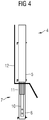
- FIG. 4 is indicated by the bold line a boundary profile 12 of the rail vehicle 1. It can be seen that the conductor section 7 in the extended position projects beyond the boundary profile 12.
- FIG. 4 shows the boarding ladder 4 according to FIG. 3 in a side view. Again, the boundary profile 12 is illustrated by a bold line. According to the invention it is ensured that in the absence of drive the boundary profile 12 is not exceeded by the extended boarding ladder. Thus, accidents are avoided in the invention.
Landscapes
- Engineering & Computer Science (AREA)
- Mechanical Engineering (AREA)
- Vehicle Step Arrangements And Article Storage (AREA)
- Ladders (AREA)
Description
- Die Erfindung betrifft ein Fahrzeug nach dem Oberbegriff des Patentanspruches 1.
- Fahrzeuge mit verlängerbaren Leitern sind aus dem Stand der Technik bereits bekannt. So weisen beispielsweise Löschfahrzeuge der Feuerwehr in der Regel eine verlängerbare Leiter auf, die mit einem Antrieb ausgerüstet ist, um die Leiter bis zu einer maximalen Länge auszufahren.
- Aus der
US 2012/0181109 A1 ist eine Zugmaschine für beispielsweise einen Schürfzug bekannt. Eine Zugangsleiter ist von einer ausgefahrenen Position, in der Zugang zur Zugmaschine möglich ist, und einer verstauten Position überführbar. Die Zugangsleiter umfasst ein längliches erstes Element mit einem ersten Tritt, der sich seitlich von diesem erstreckt. Ein längliches zweites Element ist mit dem ersten Element verbunden und relativ zu diesem verschiebbar. Von jenem erstreckt sich quer ein zweiter Tritt. Das erste Element ist an der Zugmaschine drehbar angelenkt und von einer abgesenkten ersten Position in die Stauposition schwenkbar. Dabei ist das zweite Element über eine Lenkstange mit der Zugmaschine derart verbunden, dass das zweite Element in der Zugangsposition ausgefahren und in der Stauposition bezüglich des ersten Elements eingefahren ist. - Aus der
US 5,064,022 ist eine Leiter für große Baumaschinen, wie beispielsweise Muldenkipper oder ähnliche Fahrzeuge, bekannt, die eine Bedienstation in einem beträchtlichen Abstand vom Boden aufweisen. Die ausfahrbare Leiter hat einen festen Leiterteil, der fest am Fahrzeug angebracht ist. Ein einziehbares Leiterelement ist bezüglich eines Rahmenelements der Leiter verschiebbar angeordnet. Das einziehbare Leiterelement wird durch eine elektrische Seilwinde von der Bedienstation des Fahrzeugs aus gesenkt und angehoben. - Die
US 3,774,720 offenbart eine Bootsleiter für Freizeitboote, um es einem Benutzer zu ermöglichen, einfach aus dem Boot ins Wasser und umgekehrt zu gelangen. Die Leiter umfasst einen bewegbaren Abschnitt und einen festen Abschnitt, bezüglich dessen der bewegbare Abschnitt von Hand verschiebbar ist. - In der Eisenbahntechnik werden üblicherweise Lokomotiven mit Einstiegsleitern ausgerüstet, die nicht verlängerbar sind und fest an der Seitenwand der Lokomotive befestigt sind. Die Einstiegsleiter ermöglicht dem Zugführer auch dann in den Führerraum zu gelangen, wenn die Lokomotive im freien Gelände und nicht an einem Bahnsteig abgestellt ist. Bei verlängerbaren Einstiegsleitern hat sich als nachteilig erwiesen, dass diese von Hand nur aufwändig verlängert und anschließend wieder in ihre ursprüngliche Stellung überführt werden können. Die
AU2008202858A1 - Aufgabe der Erfindung ist es, ein Fahrzeug der eingangs genannten Art bereitzustellen, das bequem zugänglich ist, wobei die Unfallgefahr minimiert ist.
- Erfindungsgemäß wird daher ein Fahrzeug mit den Merkmalen des Patentanspruches 1 vorgeschlagen. Demnach ist ein Antrieb vorgesehen, der die Einstiegsleiter von einer eingefahrenen Stellung zu einer ausgefahrenen Stellung hin überführt. Ferner sind Federmittel zum Halten der Einstiegsleiter in ihrer eingefahrenen Stellung vorgesehen, wobei der Antrieb die Einstiegsleiter entgegen der Federkraft der Federmittel verlängert und wobei die Federmittel die Einstiegsleiter bei fehlendem Antrieb in ihre eingefahrene Stellung überführen, wobei die Federmittel wenigstens eine Gasfeder aufweisen. Im Rahmen der Erfindung muss die Einstiegsleiter nicht mehr von Hand zwischen den verschiedenen Stellungen hin und her bewegt werden. Vielmehr ist es im Rahmen der Erfindung möglich, hierfür einen Antrieb einzusetzen, wobei der Antrieb beispielsweise über eine geeignete Fernsteuerung in Gang gesetzt werden kann. Ein Nutzer kann somit auch in unwegsamem Gelände oder bei großen Höhenunterschieden zwischen dem Geländeboden und der untersten Sprosse der Einstiegsleiter eine Verlängerung der Einstiegsleiter bewirken. Die Erfindung hat sich im Bereich des Schienenverkehrs als vorteilhaft erwiesen. Hintergrund ist, dass für Schienenfahrzeuge ein so genanntes Umgrenzungsprofil definiert ist. Das Schienenfahrzeug darf keine Komponenten aufweisen, welche über das Umgrenzungsprofil hinausragen, da es ansonsten zwangsläufig zu Unfällen kommen würde. Erfindungsgemäß ist die Einstiegsleiter in der eingefahrenen Stellung innerhalb des Umgrenzungsprofils angeordnet. In der ausgefahrenen Stellung überragt die Einstiegsleiter jedoch das Umgrenzungsprofil. Um Unfälle zu vermeiden, sind erfindungsgemäß Federmittel vorgesehen, die so in oder an der Einstiegsleiter und/oder dem Schienenfahrzeug befestig sind, dass die Einstiegsleiter bei fehlendem Antrieb in ihre eingefahrene Stellung überführt und/oder in dieser gehalten wird. Der Antrieb ermöglicht zwar eine Verlängerung der Einstiegsleiter nach unten. Dabei muss der Antrieb jedoch eine Antriebskraft erzeugen, welche die entgegengesetzt wirkenden Federkräfte überwindet. Die Federmittel sind hierbei so bemessen, dass die Einstiegsleiter zwischen der eingefahrenen und der maximal ausgefahrenen Stellung durch den Antrieb verschoben werden kann, ohne dass Beschädigungen an den Federmitteln auftreten, wie beispielsweise irreversible Verformungen oder dergleichen. Erfindungsgemäß umfassen die Federmittel wenigstens eine Gasfeder. Vorzugsweise sind zwei Gasfedern vorgesehen, die beispielsweise innerhalb hohler Seitenholme der Einstiegleiter angeordnet sind.
- Auch der Antrieb ist im Rahmen der Erfindung grundsätzlich beliebig. So ist der Antrieb beispielsweise ein elektrischer Antrieb.
- Vorzugsweise ist der Antrieb jedoch ein hydraulischer und bevorzugt ein pneumatischer Antrieb. Ein pneumatischer Antrieb ist insbesondere im Zusammenhang mit Fahrzeugen vorteilhaft, die aufgrund der ohnehin vorhandenen Druckluftversorgung zum Bremsen des Fahrzeugs keine zusätzlichen Motoren oder dergleichen benötigen. Die Erfindung ist somit besonders kostengünstig, wenn das Fahrzeug ein Schienenfahrzeug oder ein Lastkraftwagen ist.
- Vorteilhafterweise ist die Einstiegsleiter eine teleskopierbare Einstiegsleiter. Eine teleskopierbaren Einstiegsleiter ist besonders platzsparend. Auch dies hat sich besonders im Bereich des Schienenverkehrs als vorteilhaft erwiesen, da der Bauraum, beispielsweise von Lokomotiven, stark begrenzt ist. Gemäß einer diesbezüglichen Weiterentwicklung weist die Einstiegsleiter zwei nebeneinander liegende hohle Holme und zwischen den Holmen verlaufende Sprossen auf, wobei wenigstens ein Leiterabschnitt vorgesehen ist, der zwei nebeneinander liegende Hohlprofile aufweist, die über eine Sprosse miteinander U-förmig verbunden sind, wobei sich die freien Enden der Hohlprofile jeweils in den zugeordneten Holm oder in das zugeordnete Hohlprofil hinein erstrecken. Um ein Herausfallen aus den Holmen beziehungsweise den anderen Leiterabschnitten zu vermeiden, sind in den Holmen und/oder den Hohlprofilen zweckmäßige Anschlagschultern und Widerlager ausgebildet.
- Weitere zweckmäßige Ausgestaltungen und Vorteile der Erfindung sind Gegenstand der nachfolgenden Beschreibung von Ausführungsbeispielen der Erfindung unter Bezug auf die Figuren der Zeichnung, wobei gleiche Bezugszeichen auf gleich wirkende Bauteile verweisen und wobei
- Figur 1
- eine Teilansicht eines Ausführungsbeispiels des erfindungsgemäßen Schienenfahrzeugs,
- Figur 2
- den Einstieg des Schienenfahrzeugs gemäß
Figur 1 in einer eingefahrenen Stellung, - Figur 3
- die Einstiegsleiter gemäß
Figur 2 in einer ausgefahrenen Stellung mit eingezeichnetem Umgrenzungsprofil und - Figur 4
- die Leiter gemäß
Figur 3 in einer ausgefahrenen Stellung mit eingezeichnetem Umgrenzungsprofil zeigen. -
Figur 1 zeigt eine Teilansicht eines Ausführungsbeispiels des erfindungsgemäßen Fahrzeugs 1, bei dem es sich um ein Schienenfahrzeug handelt. Das Schienenfahrzeug 1 weist einen Wagenkasten auf, von dem lediglich ein Teil seiner Seitenwand 2 erkennbar ist. In der Seitenwand 2 ist eine Einstiegstür 3 erkennbar, die zu einem Innenraum, hier einem Führerstand einer Lokomotive, führt. Unterhalb der Fahrzeugtür 3 ist eine Einstiegsleiter 4 angeordnet, welche es dem Fahrzeugführer ermöglicht, auch auf bahnsteigfreiem Gelände bequem in den Führerstand zu gelangen. Die Einstiegsleiter 4 ist verlängerbar und weist zwei nebeneinander liegende Holme 5 auf, mit denen die Einstiegsleiter 4 an der Seitenwand 2 befestigt ist. Zwischen den Holmen 5 erstrecken sich, im Wesentlichen rechtwinklig dazu, Sprossen 6. Ferner ist ein teleskopierbarer Leiterabschnitt 7 erkennbar, der zwei nebeneinander liegende Hohlprofile 8 aufweist. Auch die Hohlprofile 8 sind durch eine Sprosse 9 miteinander verbunden. Die Hohlprofile 8 erstrecken sich mit ihrem freien, also von der Sprosse 9 abgewandten Ende jeweils in einen der hohlen Holme 5 hinein. Der Leiterabschnitt 7 ist somit U-förmig ausgebildet. Figürlich nicht dargestellte Anschlagschultern und Widerlager verhindern ein Herausfallen der beiden Hohlprofile 8 aus den Holmen 5. -
Figur 2 zeigt die Einstiegsleiter 4 in einer geschnitten Vorderansicht. Die Einstiegsleiter 4 befindet sich inFigur 2 in ihrer eingefahrenen Stellung, in der die Hohlprofile 8 nahezu vollständig innerhalb der hohlen Home 5 angeordnet sind. Ferner ist erkennbar, dass die Einstiegsleiter 4 mit Federmitteln 10 sowie mit einem Antrieb 11 ausgerüstet ist. Die Federmittel 10 umfassen zwei Gasfedern 10, die jeweils teilweise in einem pneumatischen Zylinder 11 des Antriebs angeordnet sind. Dabei ist die Gasfeder 10 in dem inFigur 2 gezeigten oberen Ende fest mit dem jeweils zugeordneten Holm 5 verbunden, wobei das andere Ende der Gasfeder 10 fest mit dem ebenfalls fest zugeordneten Hohlprofil 8 des Leiterabschnitts 4 verbunden ist. Der pneumatische Zylinder 11 ist mit einem figürlich nicht dargestellten Hauptluftbehälter der Lokomotive über ein ansteuerbares Antriebsventil verbunden. - In
Figur 3 ist die Einstiegsleiter 4 in ihrer ausgefahrenen Stellung gezeigt. Hierzu wurde der pneumatische Zylinder 11 mit Druckluft aus dem Hauptluftbehälter befüllt, wodurch die Gasfeder 10 entgegen ihrer Federkraft ausgedehnt wird. Somit ist ein pneumatischer Antrieb zum Überführen der Einstiegsleiter 4 von der eingefahrenen in ihre ausgefahrene Stellung bereitgestellt. Wird der pneumatische Zylinder 11 mittels des nicht gezeigten Antriebsventils entlüftet, stellt die Gasfeder 10 eine Rückstellkraft bereit, durch welche der Leiterabschnitt 7 in die inFigur 2 gezeigte eingefahrene Stellung überführt wird. - In
Figur 4 ist durch die fette Linie ein Umgrenzungsprofil 12 des Schienenfahrzeugs 1 angedeutet. Es ist erkennbar, dass der Leiterabschnitt 7 in der ausgefahrenen Stellung das Umgrenzungsprofil 12 überragt. - Die
Figur 4 zeigt die Einstiegsleiter 4 gemäßFigur 3 in einer Seitenansicht. Auch hier ist das Umgrenzungsprofil 12 durch eine fette Linie verdeutlicht. Erfindungsgemäß ist sichergestellt, dass bei fehlendem Antrieb das Umgrenzungsprofil 12 durch die ausgefahrene Einstiegsleiter nicht überschritten wird. Somit sind Unfälle im Rahmen der Erfindung vermieden.
Claims (5)
- Schienenfahrzeug (1), insbesondere Lokomotive, mit einer Einstiegstür (3), einer unterhalb der Einstiegstür (3) am Schienenfahrzeug (1) angeordneten Einstiegsleiter (4), die an ihrer von der Einstiegstür (4) abgewandten Seite verlängerbar ist, dadurch gekennzeichnet, dass das Schienenfahrzeug (1) einen Antrieb (11), der die Einstiegsleiter (4) von einer eingefahrenen Stellung zu einer ausgefahrenen Stellung hin überführt, und Federmittel (10) zum Halten der Einstiegsleiter (4) in ihrer eingefahrenen Stellung aufweist, wobei der Antrieb (11) die Einstiegsleiter (4) entgegen der Federkraft der Federmittel (10) verlängert, wobei die Federmittel (10) die Einstiegsleiter (4) bei fehlendem Antrieb in ihre eingefahrene Stellung überführen und wobei die Federmittel wenigstens eine Gasfeder (10) aufweisen.
- Schienenfahrzeug (1) nach Anspruch 1,
dadurch gekennzeichnet, dass der Antrieb ein hydraulischer oder ein pneumatischer Antrieb (11) ist. - Schienenfahrzeug (1) nach einem der vorhergehenden Ansprüche,
dadurch gekennzeichnet, dass die Einstiegsleiter eine teleskopierbare Einstiegsleiter (4) ist. - Schienenfahrzeug (1) nach Anspruch 3,
dadurch gekennzeichnet, dass die Einstiegsleiter (4) zwei nebeneinander liegende hohle Holme (5) und zwischen den Holmen verlaufende Sprossen (6) aufweist, wobei wenigstens ein Leiterabschnitt (7) vorgesehen ist, der zwei nebeneinander liegende Hohlprofile (8) aufweist, die über eine Sprosse (9) miteinander U-förmig verbunden sind, wobei die Hohlprofile (8) mit ihrem freien Ende in den Holmen (5) oder in den Hohlprofilen (8) eines anderen Leiterabschnitts (7) angeordnet sind. - Schienenfahrzeug (1) nach Anspruch 4,
dadurch gekennzeichnet, dass sich in jedem Holm (5) und in jedem Hohlprofil (8) eine Gasfeder (10) erstreckt, die einerseits an einem zugeordneten Holm (5) und andererseits an dem innersten Hohlprofil (8) abgestützt ist.
Priority Applications (1)
| Application Number | Priority Date | Filing Date | Title |
|---|---|---|---|
| PL13745003T PL2867066T3 (pl) | 2012-08-08 | 2013-07-22 | Pojazd z teleskopową drabinką wejściową |
Applications Claiming Priority (2)
| Application Number | Priority Date | Filing Date | Title |
|---|---|---|---|
| DE102012214089.1A DE102012214089A1 (de) | 2012-08-08 | 2012-08-08 | Fahrzeug mit teleskopierbarer Einstiegsleiter |
| PCT/EP2013/065445 WO2014023566A1 (de) | 2012-08-08 | 2013-07-22 | Fahrzeug mit teleskopierbarer einstiegsleiter |
Publications (2)
| Publication Number | Publication Date |
|---|---|
| EP2867066A1 EP2867066A1 (de) | 2015-05-06 |
| EP2867066B1 true EP2867066B1 (de) | 2017-11-01 |
Family
ID=48916003
Family Applications (1)
| Application Number | Title | Priority Date | Filing Date |
|---|---|---|---|
| EP13745003.7A Active EP2867066B1 (de) | 2012-08-08 | 2013-07-22 | Fahrzeug mit teleskopierbarer einstiegsleiter |
Country Status (11)
| Country | Link |
|---|---|
| US (1) | US20150197198A1 (de) |
| EP (1) | EP2867066B1 (de) |
| DE (1) | DE102012214089A1 (de) |
| DK (1) | DK2867066T3 (de) |
| ES (1) | ES2657280T3 (de) |
| HU (1) | HUE035372T2 (de) |
| NO (1) | NO2906531T3 (de) |
| PL (1) | PL2867066T3 (de) |
| PT (1) | PT2867066T (de) |
| RU (1) | RU2633446C2 (de) |
| WO (1) | WO2014023566A1 (de) |
Families Citing this family (14)
| Publication number | Priority date | Publication date | Assignee | Title |
|---|---|---|---|---|
| DE102014113423A1 (de) * | 2014-09-17 | 2016-03-17 | Bombardier Transportation Gmbh | Antriebseinheit für eine Trittstufe eines Schienenfahrzeugs, Trittstufeneinheit, sowie Schienenfahrzeug mit einer Trittstufeneinheit |
| US20170274828A1 (en) * | 2016-03-23 | 2017-09-28 | Ford Global Technologies, Llc | Running board assembly having multiple step pads |
| DE102016114269B4 (de) | 2016-06-06 | 2018-05-30 | Schaltbau Refurbishment Gmbh | Schwenktritt insbesondere für Schienenfahrzeuge sowie Fahrzeug mit einem solchen Schwenktritt |
| DE102016225256A1 (de) * | 2016-12-16 | 2018-06-21 | Volkswagen Aktiengesellschaft | Tritt zum Überwinden eines Höhenunterschieds durch eine Person für ein Kraftfahrzeug und/oder für einen Anhänger |
| DE102017109089A1 (de) | 2017-04-27 | 2018-10-31 | Bombardier Transportation Gmbh | Schienenfahrzeug |
| US10689012B2 (en) * | 2017-05-11 | 2020-06-23 | National Steel Car Limited | Railroad freight car access fittings |
| CN107135744B (zh) * | 2017-05-23 | 2019-10-29 | 江苏锡沂高新区科技发展有限公司 | 一种扶梯高度可调节的农业机械 |
| CN107352465A (zh) * | 2017-07-26 | 2017-11-17 | 象州县科学技术情报研究所 | 多级伸缩式液压升降台 |
| CN109955861B (zh) * | 2017-12-25 | 2020-10-23 | 比亚迪股份有限公司 | 逃生装置和具有其的轨道车辆、轨道交通系统 |
| CN111845572B (zh) * | 2019-04-28 | 2022-10-11 | 丹阳市车船装饰件有限公司 | 一种带有快速逃生装置的客车安全顶窗 |
| IT201900013872A1 (it) * | 2019-08-02 | 2021-02-02 | Hitachi Rail S P A | Sistema a scalino retraibile per la salita e la discesa in un veicolo, e gruppo porta di veicolo provvisto di tale sistema |
| CN112537255B (zh) * | 2019-09-20 | 2023-05-09 | 比亚迪股份有限公司 | 踏板组件和具有其的车辆 |
| DE102022200380A1 (de) | 2022-01-14 | 2023-07-20 | Siemens Mobility GmbH | Trittstufenanordnung und Verfahren zum Betrieb der Trittstufenanordnung |
| DE102022114028A1 (de) | 2022-06-02 | 2023-12-07 | Bode - Die Tür Gmbh | Zustiegsbaugruppe für ein Fahrzeug |
Citations (6)
| Publication number | Priority date | Publication date | Assignee | Title |
|---|---|---|---|---|
| GB326028A (en) * | 1929-03-14 | 1930-03-06 | Peters G D & Co Ltd | Improvements in movable steps for vehicles |
| DE3229533A1 (de) * | 1982-08-07 | 1984-02-09 | Rudat GmbH, 5620 Velbert | Leiter zur unterbringung in der fahrerkabine bei einer einschienenhaengebahn im bergbau |
| DE10253542A1 (de) * | 2002-11-18 | 2004-05-27 | Martin Baier | Zustiegs- und Wartungsstegsystem für grosse schienen- oder strassengebundene Arbeitsmaschinen |
| US20090008895A1 (en) * | 2007-07-04 | 2009-01-08 | Cnh America Llc | Vehicle having an Elevated Cab and Access Steps |
| AU2008202858A1 (en) * | 2007-06-29 | 2009-01-15 | Justoy Pty Ltd | Access device |
| US7905324B2 (en) * | 2004-07-15 | 2011-03-15 | Caterpillar Inc. | Access system for a moveable vehicle |
Family Cites Families (20)
| Publication number | Priority date | Publication date | Assignee | Title |
|---|---|---|---|---|
| US3033309A (en) * | 1959-11-06 | 1962-05-08 | Fugere Dale | Retractible stepladder for vehicles |
| DE6933420U (de) * | 1969-08-25 | 1970-01-29 | Karl Heinz Dipl Ing Schmidt | An fahrzeugen oder dergl. befestigbare haenge-einstiegleiter |
| US3774720A (en) * | 1971-09-09 | 1973-11-27 | C Hovey | Power-operated retractable ladder for pleasure boats |
| US3862670A (en) * | 1971-09-09 | 1975-01-28 | Cecil C Hovey | Retractable ladder for pleasure boats |
| US3951431A (en) * | 1974-12-09 | 1976-04-20 | Caterpillar Tractor Co. | Self-storing vehicle step assembly |
| SU523821A1 (ru) * | 1975-03-14 | 1976-08-05 | Центральное Конструкторское Бюро Главстроймеханизации | Складывающа с лестница |
| US4071260A (en) * | 1976-10-05 | 1978-01-31 | Marshall Sr James A | Easy cab entry and exit |
| US4200303A (en) * | 1978-06-12 | 1980-04-29 | Kelly Patrick N | Door-operated boarding step for trucks |
| US5064022A (en) * | 1989-05-30 | 1991-11-12 | Marrowbone Development Company | Ladder apparatus and method for large mobile equipment |
| DE4016620A1 (de) * | 1990-05-23 | 1991-11-28 | Man Ghh Schienenverkehr | Mehrstufiger klapptritt fuer spurgebundene fahrzeuge |
| US5427049A (en) * | 1994-06-17 | 1995-06-27 | Mardikian 1991 Irrevocable Trust | Self-retracting step assembly for personal watercraft |
| US6345691B1 (en) * | 2000-10-05 | 2002-02-12 | Windline Inc. | Ladder latch system |
| US6904863B2 (en) * | 2003-07-23 | 2005-06-14 | The Mardikian Family Trust | Self-retracting lockable step-assembly for boats |
| US9863187B2 (en) * | 2006-07-27 | 2018-01-09 | Werner Co. | Tubular access ladder and method |
| US7699328B2 (en) * | 2007-07-16 | 2010-04-20 | Timberpro Inc. | Retractable step for cab of mobile machine |
| DE202008007972U1 (de) * | 2008-06-13 | 2009-10-29 | Liebherr-Werk Ehingen Gmbh | Verfahrbares Arbeitsgerät mit einer Leiter |
| US20100012433A1 (en) * | 2008-07-18 | 2010-01-21 | Challenger Hardware Company | Self-locking extendable ladder for use with a boat |
| US8919497B2 (en) * | 2008-11-07 | 2014-12-30 | Caterpillar Inc. | Powered operator access system |
| BR112012024140A2 (pt) * | 2010-03-22 | 2016-06-28 | Barjoh Pty Ltd | sistema e dispositivo de acesso para veículos de terraplanagem, e modos de emprego dos mesmos |
| DE102012213181A1 (de) * | 2012-07-26 | 2014-02-13 | GSI Manufaktur GmbH | Ausfahrbare Leiter und Fahrzeug mit einer ausfahrbaren Leiter |
-
2012
- 2012-08-08 DE DE102012214089.1A patent/DE102012214089A1/de not_active Withdrawn
-
2013
- 2013-07-22 US US14/420,147 patent/US20150197198A1/en not_active Abandoned
- 2013-07-22 EP EP13745003.7A patent/EP2867066B1/de active Active
- 2013-07-22 PT PT137450037T patent/PT2867066T/pt unknown
- 2013-07-22 HU HUE13745003A patent/HUE035372T2/en unknown
- 2013-07-22 RU RU2015108040A patent/RU2633446C2/ru active
- 2013-07-22 PL PL13745003T patent/PL2867066T3/pl unknown
- 2013-07-22 ES ES13745003.7T patent/ES2657280T3/es active Active
- 2013-07-22 DK DK13745003.7T patent/DK2867066T3/en active
- 2013-07-22 WO PCT/EP2013/065445 patent/WO2014023566A1/de active Application Filing
- 2013-10-09 NO NO13846466A patent/NO2906531T3/no unknown
Patent Citations (6)
| Publication number | Priority date | Publication date | Assignee | Title |
|---|---|---|---|---|
| GB326028A (en) * | 1929-03-14 | 1930-03-06 | Peters G D & Co Ltd | Improvements in movable steps for vehicles |
| DE3229533A1 (de) * | 1982-08-07 | 1984-02-09 | Rudat GmbH, 5620 Velbert | Leiter zur unterbringung in der fahrerkabine bei einer einschienenhaengebahn im bergbau |
| DE10253542A1 (de) * | 2002-11-18 | 2004-05-27 | Martin Baier | Zustiegs- und Wartungsstegsystem für grosse schienen- oder strassengebundene Arbeitsmaschinen |
| US7905324B2 (en) * | 2004-07-15 | 2011-03-15 | Caterpillar Inc. | Access system for a moveable vehicle |
| AU2008202858A1 (en) * | 2007-06-29 | 2009-01-15 | Justoy Pty Ltd | Access device |
| US20090008895A1 (en) * | 2007-07-04 | 2009-01-08 | Cnh America Llc | Vehicle having an Elevated Cab and Access Steps |
Also Published As
| Publication number | Publication date |
|---|---|
| US20150197198A1 (en) | 2015-07-16 |
| NO2906531T3 (de) | 2018-06-16 |
| PL2867066T3 (pl) | 2018-04-30 |
| DE102012214089A1 (de) | 2014-02-13 |
| RU2015108040A (ru) | 2016-09-27 |
| PT2867066T (pt) | 2017-12-14 |
| ES2657280T3 (es) | 2018-03-02 |
| EP2867066A1 (de) | 2015-05-06 |
| DK2867066T3 (en) | 2018-01-15 |
| HUE035372T2 (en) | 2018-05-02 |
| RU2633446C2 (ru) | 2017-10-12 |
| WO2014023566A1 (de) | 2014-02-13 |
Similar Documents
| Publication | Publication Date | Title |
|---|---|---|
| EP2867066B1 (de) | Fahrzeug mit teleskopierbarer einstiegsleiter | |
| EP2436641B1 (de) | Teleskophubarbeitsbühne | |
| DE102006039472A1 (de) | Hubvorrichtung, insbesondere für Kraftfahrzeuge | |
| WO2013156219A1 (de) | Ausziehbarer klappaufstieg | |
| DE202017107778U1 (de) | Leitungsfahrwagen | |
| EP1842721A2 (de) | Hochbettleiter für Fahrzeuge | |
| DE102012104056A1 (de) | Ladelift für eine Ladeplattform | |
| AT513612B1 (de) | Leitersatz, insbesondere Feuerwehrleiter, sowie damit ausgestattetes Fahrzeug | |
| DE102016225256A1 (de) | Tritt zum Überwinden eines Höhenunterschieds durch eine Person für ein Kraftfahrzeug und/oder für einen Anhänger | |
| AT513614B1 (de) | Leitersatz, insbesondere Feuerwehrleiter, sowie damit ausgestattetes Fahrzeug | |
| DE102012213181A1 (de) | Ausfahrbare Leiter und Fahrzeug mit einer ausfahrbaren Leiter | |
| DE202015101409U1 (de) | Ein- und Ausfahrrampe für ein Fahrzeug | |
| DE102008007059B4 (de) | Wagenkasten eines Schienenfahrzeugs mit Notfall-Ausstiegstür | |
| DE102012104987B4 (de) | Außentritt für den Führerstand von Schienenfahrzeugen | |
| EP3549825B1 (de) | Trittstufensystem für ein fahrzeug | |
| DE102014001106B3 (de) | In eine Transportkarre umwandelbare Klappleiter | |
| DE102013014435B4 (de) | Selbsttätig verriegelndes Schwenkgelenk für eine leiterähnliche Vorrichtung und leiterähnliche Vorrichtung | |
| EP3554916B1 (de) | Schienenfahrzeug | |
| WO2018010737A2 (de) | Einsatzrampe | |
| CH703285B1 (de) | Einsatzfahrzeug mit einem Trittbrett als Einstieghilfe. | |
| DE6933420U (de) | An fahrzeugen oder dergl. befestigbare haenge-einstiegleiter | |
| EP3045330B1 (de) | Zwischen zwei gelenkig miteinander verbundenen Fahrzeugteilen angeordnete balgartige Seitenschutzwand, wobei die Seitenschutzwand an den gelenkig miteinander verbundenen Fahrzeugteilen anordbar ist | |
| EP0465985B1 (de) | Rettungskorb insbesondere eines Brandschutzfahrzeuges | |
| DE102022105087A1 (de) | Hubeinheit mit einem teleskopierbar ausgebildeten Auslegerarm und einer Spannvorrichtung | |
| DE202013007711U1 (de) | In einer Gebrauchslage selbsttätig verriegelnde Klappleiter |
Legal Events
| Date | Code | Title | Description |
|---|---|---|---|
| PUAI | Public reference made under article 153(3) epc to a published international application that has entered the european phase |
Free format text: ORIGINAL CODE: 0009012 |
|
| 17P | Request for examination filed |
Effective date: 20150202 |
|
| AK | Designated contracting states |
Kind code of ref document: A1 Designated state(s): AL AT BE BG CH CY CZ DE DK EE ES FI FR GB GR HR HU IE IS IT LI LT LU LV MC MK MT NL NO PL PT RO RS SE SI SK SM TR |
|
| AX | Request for extension of the european patent |
Extension state: BA ME |
|
| DAX | Request for extension of the european patent (deleted) | ||
| 17Q | First examination report despatched |
Effective date: 20160203 |
|
| REG | Reference to a national code |
Ref country code: DE Ref legal event code: R079 Ref document number: 502013008726 Country of ref document: DE Free format text: PREVIOUS MAIN CLASS: B60R0003020000 Ipc: E06C0001120000 |
|
| GRAP | Despatch of communication of intention to grant a patent |
Free format text: ORIGINAL CODE: EPIDOSNIGR1 |
|
| RIC1 | Information provided on ipc code assigned before grant |
Ipc: E06C 1/12 20060101AFI20170505BHEP Ipc: E06C 5/04 20060101ALI20170505BHEP Ipc: B60R 3/02 20060101ALI20170505BHEP Ipc: B61D 23/02 20060101ALI20170505BHEP |
|
| INTG | Intention to grant announced |
Effective date: 20170524 |
|
| RAP1 | Party data changed (applicant data changed or rights of an application transferred) |
Owner name: SIEMENS AKTIENGESELLSCHAFT |
|
| GRAS | Grant fee paid |
Free format text: ORIGINAL CODE: EPIDOSNIGR3 |
|
| GRAA | (expected) grant |
Free format text: ORIGINAL CODE: 0009210 |
|
| AK | Designated contracting states |
Kind code of ref document: B1 Designated state(s): AL AT BE BG CH CY CZ DE DK EE ES FI FR GB GR HR HU IE IS IT LI LT LU LV MC MK MT NL NO PL PT RO RS SE SI SK SM TR |
|
| REG | Reference to a national code |
Ref country code: GB Ref legal event code: FG4D Free format text: NOT ENGLISH |
|
| REG | Reference to a national code |
Ref country code: CH Ref legal event code: EP Ref country code: CH Ref legal event code: NV Representative=s name: SIEMENS SCHWEIZ AG, CH Ref country code: AT Ref legal event code: REF Ref document number: 942210 Country of ref document: AT Kind code of ref document: T Effective date: 20171115 |
|
| REG | Reference to a national code |
Ref country code: IE Ref legal event code: FG4D Free format text: LANGUAGE OF EP DOCUMENT: GERMAN |
|
| REG | Reference to a national code |
Ref country code: DE Ref legal event code: R096 Ref document number: 502013008726 Country of ref document: DE Ref country code: PT Ref legal event code: SC4A Ref document number: 2867066 Country of ref document: PT Date of ref document: 20171214 Kind code of ref document: T Free format text: AVAILABILITY OF NATIONAL TRANSLATION Effective date: 20171206 |
|
| REG | Reference to a national code |
Ref country code: DK Ref legal event code: T3 Effective date: 20180112 |
|
| REG | Reference to a national code |
Ref country code: RO Ref legal event code: EPE |
|
| REG | Reference to a national code |
Ref country code: SE Ref legal event code: TRGR |
|
| REG | Reference to a national code |
Ref country code: NL Ref legal event code: FP |
|
| REG | Reference to a national code |
Ref country code: ES Ref legal event code: FG2A Ref document number: 2657280 Country of ref document: ES Kind code of ref document: T3 Effective date: 20180302 |
|
| REG | Reference to a national code |
Ref country code: NO Ref legal event code: T2 Effective date: 20171101 |
|
| REG | Reference to a national code |
Ref country code: LT Ref legal event code: MG4D |
|
| REG | Reference to a national code |
Ref country code: SK Ref legal event code: T3 Ref document number: E 26204 Country of ref document: SK |
|
| PG25 | Lapsed in a contracting state [announced via postgrant information from national office to epo] |
Ref country code: LT Free format text: LAPSE BECAUSE OF FAILURE TO SUBMIT A TRANSLATION OF THE DESCRIPTION OR TO PAY THE FEE WITHIN THE PRESCRIBED TIME-LIMIT Effective date: 20171101 |
|
| REG | Reference to a national code |
Ref country code: HU Ref legal event code: AG4A Ref document number: E035372 Country of ref document: HU |
|
| PG25 | Lapsed in a contracting state [announced via postgrant information from national office to epo] |
Ref country code: IS Free format text: LAPSE BECAUSE OF FAILURE TO SUBMIT A TRANSLATION OF THE DESCRIPTION OR TO PAY THE FEE WITHIN THE PRESCRIBED TIME-LIMIT Effective date: 20180301 Ref country code: BG Free format text: LAPSE BECAUSE OF FAILURE TO SUBMIT A TRANSLATION OF THE DESCRIPTION OR TO PAY THE FEE WITHIN THE PRESCRIBED TIME-LIMIT Effective date: 20180201 Ref country code: HR Free format text: LAPSE BECAUSE OF FAILURE TO SUBMIT A TRANSLATION OF THE DESCRIPTION OR TO PAY THE FEE WITHIN THE PRESCRIBED TIME-LIMIT Effective date: 20171101 Ref country code: GR Free format text: LAPSE BECAUSE OF FAILURE TO SUBMIT A TRANSLATION OF THE DESCRIPTION OR TO PAY THE FEE WITHIN THE PRESCRIBED TIME-LIMIT Effective date: 20180202 Ref country code: RS Free format text: LAPSE BECAUSE OF FAILURE TO SUBMIT A TRANSLATION OF THE DESCRIPTION OR TO PAY THE FEE WITHIN THE PRESCRIBED TIME-LIMIT Effective date: 20171101 Ref country code: LV Free format text: LAPSE BECAUSE OF FAILURE TO SUBMIT A TRANSLATION OF THE DESCRIPTION OR TO PAY THE FEE WITHIN THE PRESCRIBED TIME-LIMIT Effective date: 20171101 |
|
| REG | Reference to a national code |
Ref country code: FR Ref legal event code: PLFP Year of fee payment: 6 |
|
| PG25 | Lapsed in a contracting state [announced via postgrant information from national office to epo] |
Ref country code: CY Free format text: LAPSE BECAUSE OF FAILURE TO SUBMIT A TRANSLATION OF THE DESCRIPTION OR TO PAY THE FEE WITHIN THE PRESCRIBED TIME-LIMIT Effective date: 20171101 Ref country code: EE Free format text: LAPSE BECAUSE OF FAILURE TO SUBMIT A TRANSLATION OF THE DESCRIPTION OR TO PAY THE FEE WITHIN THE PRESCRIBED TIME-LIMIT Effective date: 20171101 |
|
| PGFP | Annual fee paid to national office [announced via postgrant information from national office to epo] |
Ref country code: SK Payment date: 20180622 Year of fee payment: 6 |
|
| REG | Reference to a national code |
Ref country code: DE Ref legal event code: R097 Ref document number: 502013008726 Country of ref document: DE |
|
| PG25 | Lapsed in a contracting state [announced via postgrant information from national office to epo] |
Ref country code: SM Free format text: LAPSE BECAUSE OF FAILURE TO SUBMIT A TRANSLATION OF THE DESCRIPTION OR TO PAY THE FEE WITHIN THE PRESCRIBED TIME-LIMIT Effective date: 20171101 |
|
| PLBE | No opposition filed within time limit |
Free format text: ORIGINAL CODE: 0009261 |
|
| STAA | Information on the status of an ep patent application or granted ep patent |
Free format text: STATUS: NO OPPOSITION FILED WITHIN TIME LIMIT |
|
| PG25 | Lapsed in a contracting state [announced via postgrant information from national office to epo] |
Ref country code: MT Free format text: LAPSE BECAUSE OF FAILURE TO SUBMIT A TRANSLATION OF THE DESCRIPTION OR TO PAY THE FEE WITHIN THE PRESCRIBED TIME-LIMIT Effective date: 20171101 |
|
| 26N | No opposition filed |
Effective date: 20180802 |
|
| PG25 | Lapsed in a contracting state [announced via postgrant information from national office to epo] |
Ref country code: SI Free format text: LAPSE BECAUSE OF FAILURE TO SUBMIT A TRANSLATION OF THE DESCRIPTION OR TO PAY THE FEE WITHIN THE PRESCRIBED TIME-LIMIT Effective date: 20171101 |
|
| PGFP | Annual fee paid to national office [announced via postgrant information from national office to epo] |
Ref country code: HU Payment date: 20180914 Year of fee payment: 6 |
|
| REG | Reference to a national code |
Ref country code: DE Ref legal event code: R081 Ref document number: 502013008726 Country of ref document: DE Owner name: SIEMENS MOBILITY GMBH, DE Free format text: FORMER OWNER: SIEMENS AKTIENGESELLSCHAFT, 80333 MUENCHEN, DE |
|
| REG | Reference to a national code |
Ref country code: CH Ref legal event code: PUE Owner name: SIEMENS MOBILITY GMBH, DE Free format text: FORMER OWNER: SIEMENS AKTIENGESELLSCHAFT, DE |
|
| GBPC | Gb: european patent ceased through non-payment of renewal fee |
Effective date: 20180722 |
|
| PG25 | Lapsed in a contracting state [announced via postgrant information from national office to epo] |
Ref country code: MC Free format text: LAPSE BECAUSE OF FAILURE TO SUBMIT A TRANSLATION OF THE DESCRIPTION OR TO PAY THE FEE WITHIN THE PRESCRIBED TIME-LIMIT Effective date: 20171101 Ref country code: LU Free format text: LAPSE BECAUSE OF NON-PAYMENT OF DUE FEES Effective date: 20180722 |
|
| REG | Reference to a national code |
Ref country code: IE Ref legal event code: MM4A |
|
| PG25 | Lapsed in a contracting state [announced via postgrant information from national office to epo] |
Ref country code: GB Free format text: LAPSE BECAUSE OF NON-PAYMENT OF DUE FEES Effective date: 20180722 Ref country code: IE Free format text: LAPSE BECAUSE OF NON-PAYMENT OF DUE FEES Effective date: 20180722 |
|
| REG | Reference to a national code |
Ref country code: AT Ref legal event code: PC Ref document number: 942210 Country of ref document: AT Kind code of ref document: T Owner name: SIEMENS MOBILITY GMBH, DE Effective date: 20190506 |
|
| REG | Reference to a national code |
Ref country code: NO Ref legal event code: CHAD Owner name: SIEMENS MOBILITY GMBH, DE |
|
| REG | Reference to a national code |
Ref country code: NL Ref legal event code: PD Owner name: SIEMENS MOBILITY GMBH; DE Free format text: DETAILS ASSIGNMENT: CHANGE OF OWNER(S), ASSIGNMENT; FORMER OWNER NAME: SIEMENS AKTIENGESELLSCHAFT Effective date: 20190829 |
|
| PGFP | Annual fee paid to national office [announced via postgrant information from national office to epo] |
Ref country code: NO Payment date: 20190722 Year of fee payment: 7 Ref country code: DK Payment date: 20190723 Year of fee payment: 7 |
|
| REG | Reference to a national code |
Ref country code: BE Ref legal event code: PD Owner name: SIEMENS MOBILITY GMBH; DE Free format text: DETAILS ASSIGNMENT: CHANGE OF OWNER(S), CESSION; FORMER OWNER NAME: SIEMENS AKTIENGESELLSCHAFT Effective date: 20190911 |
|
| PG25 | Lapsed in a contracting state [announced via postgrant information from national office to epo] |
Ref country code: TR Free format text: LAPSE BECAUSE OF FAILURE TO SUBMIT A TRANSLATION OF THE DESCRIPTION OR TO PAY THE FEE WITHIN THE PRESCRIBED TIME-LIMIT Effective date: 20171101 |
|
| REG | Reference to a national code |
Ref country code: SK Ref legal event code: MM4A Ref document number: E 26204 Country of ref document: SK Effective date: 20190722 |
|
| PG25 | Lapsed in a contracting state [announced via postgrant information from national office to epo] |
Ref country code: HU Free format text: LAPSE BECAUSE OF NON-PAYMENT OF DUE FEES Effective date: 20190723 |
|
| PG25 | Lapsed in a contracting state [announced via postgrant information from national office to epo] |
Ref country code: SK Free format text: LAPSE BECAUSE OF NON-PAYMENT OF DUE FEES Effective date: 20190722 |
|
| PG25 | Lapsed in a contracting state [announced via postgrant information from national office to epo] |
Ref country code: MK Free format text: LAPSE BECAUSE OF NON-PAYMENT OF DUE FEES Effective date: 20171101 |
|
| PG25 | Lapsed in a contracting state [announced via postgrant information from national office to epo] |
Ref country code: AL Free format text: LAPSE BECAUSE OF FAILURE TO SUBMIT A TRANSLATION OF THE DESCRIPTION OR TO PAY THE FEE WITHIN THE PRESCRIBED TIME-LIMIT Effective date: 20171101 |
|
| REG | Reference to a national code |
Ref country code: ES Ref legal event code: PC2A Owner name: SIEMENS MOBILITY GMBH Effective date: 20200805 |
|
| PGFP | Annual fee paid to national office [announced via postgrant information from national office to epo] |
Ref country code: RO Payment date: 20200714 Year of fee payment: 8 |
|
| REG | Reference to a national code |
Ref country code: DK Ref legal event code: EBP Effective date: 20200731 Ref country code: NO Ref legal event code: MMEP |
|
| PG25 | Lapsed in a contracting state [announced via postgrant information from national office to epo] |
Ref country code: NO Free format text: LAPSE BECAUSE OF NON-PAYMENT OF DUE FEES Effective date: 20200731 |
|
| PG25 | Lapsed in a contracting state [announced via postgrant information from national office to epo] |
Ref country code: DK Free format text: LAPSE BECAUSE OF NON-PAYMENT OF DUE FEES Effective date: 20200731 |
|
| PG25 | Lapsed in a contracting state [announced via postgrant information from national office to epo] |
Ref country code: RO Free format text: LAPSE BECAUSE OF NON-PAYMENT OF DUE FEES Effective date: 20210722 |
|
| PGFP | Annual fee paid to national office [announced via postgrant information from national office to epo] |
Ref country code: PT Payment date: 20230620 Year of fee payment: 11 |
|
| PGFP | Annual fee paid to national office [announced via postgrant information from national office to epo] |
Ref country code: NL Payment date: 20230710 Year of fee payment: 11 |
|
| PGFP | Annual fee paid to national office [announced via postgrant information from national office to epo] |
Ref country code: IT Payment date: 20230725 Year of fee payment: 11 Ref country code: FI Payment date: 20230719 Year of fee payment: 11 Ref country code: CZ Payment date: 20230717 Year of fee payment: 11 Ref country code: AT Payment date: 20230609 Year of fee payment: 11 |
|
| PGFP | Annual fee paid to national office [announced via postgrant information from national office to epo] |
Ref country code: SE Payment date: 20230720 Year of fee payment: 11 Ref country code: PL Payment date: 20230714 Year of fee payment: 11 Ref country code: FR Payment date: 20230720 Year of fee payment: 11 Ref country code: DE Payment date: 20230918 Year of fee payment: 11 Ref country code: BE Payment date: 20230719 Year of fee payment: 11 |
|
| PGFP | Annual fee paid to national office [announced via postgrant information from national office to epo] |
Ref country code: ES Payment date: 20231023 Year of fee payment: 11 |
|
| PGFP | Annual fee paid to national office [announced via postgrant information from national office to epo] |
Ref country code: CH Payment date: 20231024 Year of fee payment: 11 |