EP2865817A1 - Garniture d'écoulement pour une chasse d'eau - Google Patents
Garniture d'écoulement pour une chasse d'eau Download PDFInfo
- Publication number
- EP2865817A1 EP2865817A1 EP20130190455 EP13190455A EP2865817A1 EP 2865817 A1 EP2865817 A1 EP 2865817A1 EP 20130190455 EP20130190455 EP 20130190455 EP 13190455 A EP13190455 A EP 13190455A EP 2865817 A1 EP2865817 A1 EP 2865817A1
- Authority
- EP
- European Patent Office
- Prior art keywords
- control unit
- full
- valve body
- quantity control
- subset
- Prior art date
- Legal status (The legal status is an assumption and is not a legal conclusion. Google has not performed a legal analysis and makes no representation as to the accuracy of the status listed.)
- Granted
Links
- XLYOFNOQVPJJNP-UHFFFAOYSA-N water Substances O XLYOFNOQVPJJNP-UHFFFAOYSA-N 0.000 claims abstract description 54
- 230000036961 partial effect Effects 0.000 claims abstract description 48
- 238000005192 partition Methods 0.000 claims abstract description 34
- 230000033001 locomotion Effects 0.000 claims abstract description 19
- 238000007789 sealing Methods 0.000 claims abstract description 12
- 238000010926 purge Methods 0.000 claims abstract description 11
- 238000011010 flushing procedure Methods 0.000 claims description 21
- 239000002699 waste material Substances 0.000 claims description 9
- 238000009434 installation Methods 0.000 claims description 5
- 238000004891 communication Methods 0.000 description 3
- 238000000034 method Methods 0.000 description 3
- 230000002829 reductive effect Effects 0.000 description 3
- 230000002000 scavenging effect Effects 0.000 description 3
- 230000003213 activating effect Effects 0.000 description 1
- 230000005540 biological transmission Effects 0.000 description 1
- 230000001419 dependent effect Effects 0.000 description 1
- 230000000670 limiting effect Effects 0.000 description 1
- 230000014759 maintenance of location Effects 0.000 description 1
- 230000000284 resting effect Effects 0.000 description 1
- 230000002441 reversible effect Effects 0.000 description 1
- 239000008237 rinsing water Substances 0.000 description 1
- 230000000630 rising effect Effects 0.000 description 1
Images


Classifications
-
- E—FIXED CONSTRUCTIONS
- E03—WATER SUPPLY; SEWERAGE
- E03D—WATER-CLOSETS OR URINALS WITH FLUSHING DEVICES; FLUSHING VALVES THEREFOR
- E03D3/00—Flushing devices operated by pressure of the water supply system flushing valves not connected to the water-supply main, also if air is blown in the water seal for a quick flushing
- E03D3/12—Flushing devices discharging variable quantities of water
-
- E—FIXED CONSTRUCTIONS
- E03—WATER SUPPLY; SEWERAGE
- E03D—WATER-CLOSETS OR URINALS WITH FLUSHING DEVICES; FLUSHING VALVES THEREFOR
- E03D1/00—Water flushing devices with cisterns ; Setting up a range of flushing devices or water-closets; Combinations of several flushing devices
- E03D1/02—High-level flushing systems
- E03D1/14—Cisterns discharging variable quantities of water also cisterns with bell siphons in combination with flushing valves
- E03D1/142—Cisterns discharging variable quantities of water also cisterns with bell siphons in combination with flushing valves in cisterns with flushing valves
- E03D1/144—Cisterns discharging variable quantities of water also cisterns with bell siphons in combination with flushing valves in cisterns with flushing valves having a single flush outlet and an additional float for delaying the valve closure
-
- E—FIXED CONSTRUCTIONS
- E03—WATER SUPPLY; SEWERAGE
- E03D—WATER-CLOSETS OR URINALS WITH FLUSHING DEVICES; FLUSHING VALVES THEREFOR
- E03D1/00—Water flushing devices with cisterns ; Setting up a range of flushing devices or water-closets; Combinations of several flushing devices
- E03D1/30—Valves for high or low level cisterns; Their arrangement ; Flushing mechanisms in the cistern, optionally with provisions for a pre-or a post- flushing and for cutting off the flushing mechanism in case of leakage
- E03D1/34—Flushing valves for outlets; Arrangement of outlet valves
- E03D1/35—Flushing valves having buoyancy
-
- E—FIXED CONSTRUCTIONS
- E03—WATER SUPPLY; SEWERAGE
- E03D—WATER-CLOSETS OR URINALS WITH FLUSHING DEVICES; FLUSHING VALVES THEREFOR
- E03D1/00—Water flushing devices with cisterns ; Setting up a range of flushing devices or water-closets; Combinations of several flushing devices
- E03D1/30—Valves for high or low level cisterns; Their arrangement ; Flushing mechanisms in the cistern, optionally with provisions for a pre-or a post- flushing and for cutting off the flushing mechanism in case of leakage
- E03D1/34—Flushing valves for outlets; Arrangement of outlet valves
-
- E—FIXED CONSTRUCTIONS
- E03—WATER SUPPLY; SEWERAGE
- E03D—WATER-CLOSETS OR URINALS WITH FLUSHING DEVICES; FLUSHING VALVES THEREFOR
- E03D1/00—Water flushing devices with cisterns ; Setting up a range of flushing devices or water-closets; Combinations of several flushing devices
- E03D1/02—High-level flushing systems
- E03D1/14—Cisterns discharging variable quantities of water also cisterns with bell siphons in combination with flushing valves
- E03D2001/147—Cisterns discharging variable quantities of water also cisterns with bell siphons in combination with flushing valves having provisions for active interruption of flushing
Definitions
- the present invention relates to a drain fitting or a drain valve for a cistern according to the preamble of claim 1.
- a weight body is arranged, which can optionally be switched on the valve body.
- the flushing device of the EP 0 722 020 is designed with respect to reliability and longevity extraordinarily good and very satisfactory, the control unit or the flush volume is very limited adjustable.
- the invention has for its object to provide a waste set, which overcomes the disadvantages of the prior art.
- a waste set should be specified, with which a more flexible adjustment of the full flush and the partial flush can be achieved.
- a larger adjustment range for the two flushing quantities should be achieved.
- an expiration set comprises a valve body with a valve seat cooperating with a sealing member and a float, wherein the valve body with the sealing element from the valve seat along a movement axis of a rest position in the scavenge and movable from the scavenge to the rest position , a full-quantity control unit for controlling a full-flush, wherein the full-amount control provides a closing force to the valve body when a full-level water level is reached, and a partial quantity control unit for controlling a partial-quantity purge, wherein the partial quantity controller achieves a closing force upon reaching a partial water level on the valve body provides.
- the drain fitting comprises a partition with a float chamber below it, wherein the valve body extends through an opening through the partition wall, wherein the float is movable within the float chamber along the actuating axis and cooperates with this hydraulically.
- the partition wall has a full-quantity control opening and a partial quantity control opening through which air and / or water can pass from below the upper side of the partition so that the pressure ratios between the float chamber and the areas outside the float chamber can be compensated. The hydraulic balance within the float chamber is thus disturbed.
- the state of the full-quantity control opening and the partial-quantity control opening is controllable by the full-quantity control unit and the subset control unit.
- the arrangement of the control openings in the partition wall, the area above the partition remains substantially free. This area can then be used for the design of the subset control unit and the full amount control unit. Consequently, the arrangement of the control openings in the partition a greater freedom of design for the design of the control units are created.
- the closing force is a mechanical closing force acting on the float in the direction of the axis of movement.
- the closing force is provided by mechanical contact between parts of the full-quantity control unit and the partial quantity control unit.
- the control openings are controlled in accordance with the intended flushing. Consequently, therefore, act on the valve body in the process of closing a mechanical force component, which is acted upon by the closing force on the valve body, and a hydraulic component, which is provided by the control of the control opening. Due to the hydraulic influence via the active control of the control openings, the mechanical closing force can be reduced.
- the float chamber is bounded at the top by the partition wall and downwardly extends a side wall, which adjoins the partition wall.
- the side wall has an edge region, which is spaced from the valve seat, so that between the edge and the valve seat, the rinse water can flow to the drain of the cistern.
- the closing force of the respective control unit is applied directly to the valve body or via a switching element of the respective control unit on the valve body.
- each of the control unit comprises a closure member which cooperates with the respective control opening, wherein the closure member is movable relative to the corresponding control opening.
- the closure member which is part of the full-quantity control unit or the partial quantity control unit, therefore, the full-quantity control opening and the partial quantity control opening can be activated actively become.
- the full-quantity control unit has an operating rod which projects through the full-quantity control opening and acts directly on the float.
- said closing force can be applied to the valve body on the float.
- the actuating rod is movable relative to the fixed partition wall.
- the actuating rod protrudes into the float chamber so far that during the movement of the float from the rest position into the flushing position, the actuating rod and further parts of the full-quantity control unit are raised.
- the closure member is arranged.
- the closure member cooperates with the control port.
- the closure member is located within the float chamber such that the full-quantity control opening is closable when the valve body is in the rest position.
- the control port remains closed until the water level has dropped to the full level, and then the control port is opened by the full amount control unit.
- the full-quantity control unit comprises an actuating element with a water chamber, wherein the actuating element is in communication with the actuating rod.
- the actuating element can be moved and locked relative to the actuating rod, so that its height is adjustable in the cistern.
- the actuating rod preferably on locking elements.
- the water chamber fills with increasing rinse water in a cistern with the rinse water.
- the rinsing water in the water chamber becomes effective as a weight force and provides said closing force on the valve body.
- the shutter member of the full-quantity control unit is moved away from the full-quantity control port and the float chamber becomes open.
- air and / or water can enter the float chamber through the full flow control orifice, thereby disturbing the hydraulic balance within the float chamber.
- the valve body is moved from the scavenge to its rest position.
- the subset control unit remains occluded.
- the subset control unit remains at the Vollmengen Introduceung substantially in its rest position and is not operated.
- the actuating rod of the full amount control unit is mounted in a flushing position on a retaining element.
- the retention element provides a stop against movement beyond the scavenge position.
- actuating rod is preferably mounted movably in a longitudinal guide.
- the longitudinal guide extends in the direction of actuation.
- the actuating element has an air chamber which lies below the said water chamber, so that the actuating element and thus also the actuating rod and the closure member undergo buoyancy and the closure member closes the full-quantity control opening when the cistern is filled.
- the subset control unit comprises a switching element which automatically engages with the valve body when the subset control unit is raised.
- the mechanical closing force can be transferred from the subset control unit to the valve body.
- the subset control unit comprises a rod, wherein at a front end portion, a closure member is arranged.
- the closure member cooperates with the partial quantity control opening.
- the closure member is raised by the subset control opening upon actuation of the subset control unit.
- the closing member of the subset control unit preferably opens the subset control opening only when the subset control unit is operated. This means that otherwise, ie when the subset control unit is not actuated, the subset control opening remains closed.
- the partial flow control opening is open, water can flow into the float chamber, in which case the hydraulic equilibrium is correspondingly influenced.
- the state of the full-quantity control opening is closed at the subset control.
- the closing member of the full-quantity control unit closes the full-quantity control opening, so that the float chamber is closed at the top.
- the closure is achieved in particular by the buoyancy of the actuating element with the air chamber.
- the closure member of the Operamengenpültician is outside the float chamber.
- the subset control unit comprises an actuating element with a water chamber, wherein the actuating element via the switching member to the valve body is switchable and wherein the actuating element with the rod, in particular adjustable, is in communication.
- the water chamber provides a weight with empty cistern, which then acts as a closing force. The closing force is transferred as mentioned via the switching element on the valve body.
- the actuating element of the full-quantity control unit lies in the installed position below the actuating element of the partial quantity control unit. Both actuators can be adjusted in height in the cistern preferably.
- the drain fitting further comprises an actuating device.
- the actuator acts on the full body flushing directly on the valve body.
- the valve body is raised accordingly.
- the full-quantity control unit acts on the valve body for the movement from the scavenge to the rest position. In the partial flush, the actuator over the subset control unit on the valve body, wherein the subset control unit is raised in the actuation and at the same time lifts the valve body, wherein the subset control unit with the valve body, in particular via the switching member, is temporarily connectable.
- the subset control unit comprises a sleeve-related sleeve which at least partially surrounds the valve body, the valve body having a stopper against which the sleeve abuts in the partial quantity purge such that the valve body can be raised.
- the valve body has a receiving opening engaged with the operating device
- the partial quantity control unit has a receiving opening which engages with the operating device.
- the elements are moved from the rest position to the rinse.
- the actuating rods of the full amount control unit and the rod of the subset control unit are movable along a longitudinal direction parallel to the movement of the valve body.
- the full-quantity control opening and the partial quantity control opening are arranged in a section of the partition wall lying in the installation position in the horizontal.
- the full-quantity control opening and the partial quantity control opening are in the installation position with respect to the horizontal on the same plane.
- the drain fitting further comprises a housing which is firmly connected to the cistern, wherein the valve body is movably mounted in the housing.
- the housing moreover preferably comprises the float chamber and the partition wall.
- closure members of the two control units can be interleaved with each other.
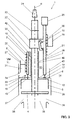
- FIG. 1 a waste set 1 for a cistern in the rest position is shown.
- the cistern is not shown here.
- the waste set 1 is connected in a known manner with the cistern and is used to control a Generalmengen facedung or a full flush. When flushing a certain amount of water to a sanitary device, such as a toilet or a urinal is supplied.
- the drain fitting 1 comprises a valve body 2 with a sealing element 4 and a float 5, a full amount control unit 6 and a partial quantity control unit 7. Further, the drain set comprises a partition 8 with a below this float chamber 9, in which the float 5 is arranged to be movable.
- valve body 2 is connected to the sealing element 4 by a valve seat 3 along a movement axis B from a rest position to a scavenge position and from the scavenge position into the Resting position movable.
- FIG. 1 is the valve body 2 in the rest position, in which case the sealing element 4 rests against the valve seat 3, so that no water can the drain 35, which adjoins the valve seat 3, can be fed.
- Valve seat 3 and drain 35 may be parts of the drain fitting 1 or the cistern.
- the full-quantity control unit 6 is for controlling a full-quantity purging.
- the full-quantity control unit 6 provides a closing force F on the valve body 2 when a water level intended for the full amount is reached, denoted by VM in the figures.
- the full-quantity control unit 6 thus causes a mechanical closing force F on the valve body 2, so that it is moved back from the scavenging position to the rest position.
- the subset control unit 7 is for controlling a subset purge.
- the subset control unit 7 upon reaching a water level intended for the subset, denoted by TM in the figures, provides a closing force F on the valve body 2. Again, a mechanical force is provided on the valve body 2, so that it is moved back from the spill position to the rest position.
- the drain fitting 1 comprises a partition wall 8 with a float chamber 9 located below this partition 8.
- the float chamber 9 is bounded at the top by the partition 8.
- a side wall 36 extends away from the partition wall 8 and limits the float chamber 9 laterally.
- the side wall 36 adjoins the partition 8 and surrounds this circumferentially.
- the side wall 36 Towards the bottom, ie against the valve seat 3, the side wall 36 has an edge region 37. This edge region 37 is spaced from the valve seat 3, so that between the valve seat 3 and the edge portion 37, a gap 38 is provided, through which the rinse water 35 can be supplied.
- the partition wall 8 has an opening 10 through which the valve body 2 extends.
- the valve body 2 is mounted movably in the opening 10 along the actuation axis B.
- the float 5 is located here within the float chamber 9 and is movable along the actuating axis B.
- the float 5 works hydraulically with the float chamber 9 together. Due to the conclusion after At the top through the partition wall 8 is formed with raised float 9, when the valve body 2 is in the scavenge, a hydraulic balance within the float chamber 9, wherein the float 5 is held in the scavenge position due to this balance. In other words, a negative pressure is provided in the float chamber 9, which keeps the float 5 and thus also the valve body 2 in the flushing position.
- the opening 10 is supplemented with a circumferential wall 39 upwards.
- the wall 39 provides an opening 40 which correspondingly guides the valve body 2 and seals against entry of air.
- the wall 39 extends completely around the opening 10, in which case the wall 39 provides the cylindrical uninterrupted opening 40.
- two control openings 11, 12 are arranged in the partition 8.
- these control openings 11, 12, which can be opened or closed the hydraulic balance within the float chamber 9 can be controlled. If one of these control openings 11, 12 is opened when the float 5 is in the flushing position, the hydraulic equilibrium in the float chamber 9 is released and the float 5 moves along the actuation axis B in the direction of the valve seat 3.
- a full-quantity control port 11 and a sub-quantity control port 12 are arranged. Through these control openings 11, 12, air and / or water from the top 13 of the partition 8 below this, so in the float chamber 9, reach. Thus, the pressure conditions between the float chamber 9 and the areas 14 outside the float chamber 9 can be compensated.
- the areas 14 are provided by the cistern.
- the state of the full-quantity control port 11 and the state of the sub-quantity control port 12 are controlled by the full-quantity control unit 6 and the subset control unit 7. In the full-flush, the full-quantity control port 11 is opened and the partial-quantity control port 12 remains in the closed state.
- the subset control unit 7 is operated the operation of the control openings 11, 12 exactly the reverse, there, the partial flow control opening 12 is opened and the full-quantity control opening 11 remains closed.
- a mechanical closing force F is provided on the valve body 2, and on the other hand, a hydraulic component acts through the opening of the control openings 11, 12. Due to the hydraulic control by the control openings 11, 12, the closing force F, which by the full amount control unit 6 and by the Subset control unit 7 is to be provided reduced. As a result, the mass of the partial quantity control unit 7 or of the full quantity control unit 6 can be reduced accordingly.
- the waste set is displayed during full flush.
- the sealing element 4 is here spaced from the valve seat 3.
- the entire valve body 2 is raised.
- the rinse water can pass through the gap 38 to the drain 35.
- the water level in the cistern drops accordingly.
- the weight force of the full-quantity control unit 6 starts to act and the full-quantity control unit 6 provides a closing force F on the valve body 2, here on the float 5.
- This closing force F pushes the valve body 2 along the movement axis B toward the valve seat 3.
- the full-quantity control opening 11 is opened by the full-quantity control unit 6 and the hydraulic balance in the float chamber 9 is disturbed.
- a hydraulic component is also provided on the valve body 2, which allows the valve body 2 to move in the direction of the valve seat 3.
- the subset control opening 12 remains closed because the subset control unit 7 not operated.
- the subset control unit 7 is pressed against the subset control opening 12 due to its weight.
- the subset control unit 7 is correspondingly operated and raises the valve body 2.
- a Heidelbergorgang 15 is provided in the embodiment shown.
- the subset control opening 12 is already opened.
- the weight force of the subset control unit 7 begins to act and provides a closing force F on the valve body 2 via the switching element 15.
- the hydraulic balance within the float chamber 9 is disturbed by the already opened subset control opening 12. It can reach water via the partial quantity control opening 12 in the float chamber 9.
- mechanical and hydraulic force components also act on the valve body 2, so that it can be closed accordingly.
- the full-quantity control port 11 remains closed.
- Each of the control units 6, 7 comprises a closure member 16, 17, which cooperates with the respective control opening 11, 12.
- the closure member 16, 17 is movable by the control unit 6, 7 relative to the corresponding control opening 11, 12.
- the closure member 16, 17 may be formed in various ways. In the present embodiment, each of the closure members 16 or 17 on a valve plate, which is larger than corresponding control opening 11, 12 and so closes them.
- the full-quantity control unit 6 has an actuating rod 18.
- the operating rod 18 protrudes through the full-quantity control opening 11 in the present embodiment and acts directly on the float 5.
- This actuating rod 18 is the closing force F applied to the float 5.
- the actuating rod 18 is here with an actuating element 27 in connection.
- the actuating element 27 has, in the present embodiment, a water chamber 28 and an air chamber 31 located below the water chamber 28.
- the water chamber 28 fills with rising water level in the cistern with rinse water.
- the air chamber 31 provides a corresponding lift, so that the closure member 16 rests against the full-quantity control opening 11 in the rest position.
- the actuator 27 is slidable and adjustable relative to the actuating rod 18.
- This height adjustment controls the level of full-volume control and thus also the volume removal from the cistern during full-volume control.
- FIG. 1 can be well recognized that the actuating rod 18 protrudes into the float chamber 9 so far that during the movement of the float from the rest position into the flushing position, the actuating rod 18 and other parts of the full amount control unit 6 is raised.
- the closure member 16 is arranged on the actuating rod 18.
- the closure member 16 is located within the float chamber 5.
- the closure member 16 is located in the float chamber 9 such that in the raised state, the full-quantity control opening 11 can be closed. The closure is ensured by the buoyancy of the actuating element 27.
- the actuating rod 18 of the full-quantity control unit 6 can be suspended in a rinsing position on a retaining element 20.
- the retaining element 20 provides a stop for the actuating rod 18 with respect to a movement in the direction of the float chamber 9 ready.
- the function of this stop is in the FIG. 1 shown accordingly.
- the actuating rod 18 is guided in the region of the stop with a longitudinal guide on the drain fitting. In the FIG. 5 an exemplary longitudinal guide 41 is shown.
- the subset control unit 12 comprises a switching element 15.
- the switching element 15, which here has the shape of a shift lever, is automatically connected to the valve body 2 when the subset control unit 12 is raised.
- the switching element 15 is present at a stop element 42 on the valve body 2.
- the closing force F is transferred from the subset control unit 12 to the valve body 2 accordingly.
- the switching member 15 pivots back automatically, so that the connection between the subset control unit 7 and valve body 2 is released.
- the partial quantity control unit 12 comprises a rod 21, the closure member 17 being arranged at a front end region 19.
- the closure member 17 is raised accordingly by the subset control opening 12 and releases it.
- the closure member 17 is arranged outside the float chamber 9. The shutter 17 is moved toward the sub-quantity control opening via the weight force of the sub-quantity control unit 7.
- the subset control unit 7 also has an actuator.
- the actuating element of the partial quantity control unit 7 bears the reference numeral 29.
- the actuating element 29 in this case comprises a water chamber and communicates with the rod 21 in connection.
- the actuator 29 can be relatively move along the rod 21 and set.
- the actuating element 29 can be connected via the switching element 15 to the valve body 2.
- the water in the water chamber 30 acts as a weight and acts via the switching element 15 on the valve body 2, so that it can be moved from the scavenging position to the rest position.
- the mechanical closing force F is provided.
- the drain fitting 1 on an actuating device acts directly on the valve body 2.
- the valve body 2 has a at its upper end Receiving opening 24, in which the actuating device can engage accordingly.
- the actuating device acts on the valve body 2 during the partial quantity flushing via the partial quantity control unit 7.
- the partial quantity control unit 7 is raised accordingly and at the same time raises the valve body 2.
- the subset control unit 7 is temporarily connected to the valve body 2 via the switching member 15, so that the closing force F can be transmitted from the subset control unit 7 to the valve body 2.
- the partial quantity control unit 7 has a sleeve 22 connected to the rod 21 for the transmission of motion to the valve body 2.
- the sleeve 22 surrounds the valve body 2 at least partially.
- the valve body 2 has a stop 23, on which the collar 22 is present in the partial flushing in such a way that the valve body 2 can be raised accordingly.
- the stop 23 thus lies above the sleeve 22.
- the partial quantity control unit 7 has a receiving opening 25.
- the receiving opening 25 is here in the region of the rod 21 with the subset control unit 7 in connection.
- the receiving opening 25 is for engagement with the actuating device. About this receiving opening the subset control unit 7 is raised accordingly.
- the partial quantity control unit 7 and also the full-quantity control unit 6 move substantially parallel to the movement of the valve body.
- the full-quantity control port 11 and the sub-quantity control port 12 are in an installation position in the horizontal portion 26 of the partition wall 8. More preferably, the full-quantity control port 11 and the sub-quantity control port 12 are substantially on the same plane. This in turn in relation to the horizontal. Alternatively, the two control openings 11, 12 in height also be offset from one another.
- the actuator 27 of the full-quantity control unit 6 is in a container 32nd movable.
- the container 32 adjoins the partition wall 8. Above the dividing wall 8, in the region of the container bottom 32, the container has an outlet opening 34.
- the container has the function of slightly slowing down the movement of the full-quantity control unit 6 by slowly pushing the water in the container 32 outward via the outlet opening 34.
- a corresponding container 43 is provided in the area of the subset control unit 7.
- This container 43 essentially ensures that the hydraulic balance within the float chamber is not canceled too soon when a partial flush is initiated.
- the container 43 is arranged in the region of the partial quantity control opening and extends away from the dividing wall 9.
- FIG. 5 a perspective view of a preferred embodiment of the drain fitting 1 is shown.
- the drain fitting 1 here further comprises a housing 44 which is firmly connected to the cistern.
- the valve body 2 and the other movable elements are in communication with the housing 44 accordingly.
- the actuators 27, 29 along the corresponding rods 18, 21 are formed adjustable in height.
Landscapes
- Health & Medical Sciences (AREA)
- Life Sciences & Earth Sciences (AREA)
- Engineering & Computer Science (AREA)
- Hydrology & Water Resources (AREA)
- Public Health (AREA)
- Water Supply & Treatment (AREA)
- Float Valves (AREA)
- Sanitary Device For Flush Toilet (AREA)
Priority Applications (5)
| Application Number | Priority Date | Filing Date | Title |
|---|---|---|---|
| EP13190455.9A EP2865817B1 (fr) | 2013-10-28 | 2013-10-28 | Garniture d'écoulement pour une chasse d'eau |
| ES13190455T ES2570974T3 (es) | 2013-10-28 | 2013-10-28 | Adaptador de desagüe para una cisterna de lavado |
| AU2014250737A AU2014250737A1 (en) | 2013-10-28 | 2014-10-20 | Drainage fitting for a cistern |
| US14/524,050 US9695582B2 (en) | 2013-10-28 | 2014-10-27 | Drainage fitting for a cistern |
| CN201410581771.4A CN104563240B (zh) | 2013-10-28 | 2014-10-27 | 用于水箱的排水配件 |
Applications Claiming Priority (1)
| Application Number | Priority Date | Filing Date | Title |
|---|---|---|---|
| EP13190455.9A EP2865817B1 (fr) | 2013-10-28 | 2013-10-28 | Garniture d'écoulement pour une chasse d'eau |
Publications (2)
| Publication Number | Publication Date |
|---|---|
| EP2865817A1 true EP2865817A1 (fr) | 2015-04-29 |
| EP2865817B1 EP2865817B1 (fr) | 2016-03-02 |
Family
ID=49488482
Family Applications (1)
| Application Number | Title | Priority Date | Filing Date |
|---|---|---|---|
| EP13190455.9A Active EP2865817B1 (fr) | 2013-10-28 | 2013-10-28 | Garniture d'écoulement pour une chasse d'eau |
Country Status (5)
| Country | Link |
|---|---|
| US (1) | US9695582B2 (fr) |
| EP (1) | EP2865817B1 (fr) |
| CN (1) | CN104563240B (fr) |
| AU (1) | AU2014250737A1 (fr) |
| ES (1) | ES2570974T3 (fr) |
Cited By (2)
| Publication number | Priority date | Publication date | Assignee | Title |
|---|---|---|---|---|
| EP3467215A1 (fr) * | 2017-10-05 | 2019-04-10 | Geberit International AG | Raccord fileté d'évacuation |
| EP4112830A4 (fr) * | 2020-02-28 | 2023-08-02 | Toto Ltd. | Dispositif de réservoir d'eau de rinçage et dispositif de rinçage de toilettes le comportant |
Families Citing this family (8)
| Publication number | Priority date | Publication date | Assignee | Title |
|---|---|---|---|---|
| JP6766324B2 (ja) * | 2015-06-15 | 2020-10-14 | Toto株式会社 | 排水弁装置、洗浄水タンク装置および水洗大便器 |
| DE102015016737A1 (de) * | 2015-12-22 | 2017-06-22 | GROHEDAL Sanitärsysteme GmbH | Ablaufgarnitur für einen Spülkasten |
| PL3538716T3 (pl) * | 2016-11-09 | 2021-07-19 | Geberit International Ag | Armatura spustowa |
| AU2018346310A1 (en) * | 2017-10-03 | 2020-04-23 | Fluidmaster, Inc. | Discharge valve system and method |
| WO2021171966A1 (fr) * | 2020-02-28 | 2021-09-02 | Toto株式会社 | Dispositif de réservoir d'eau de lavage et dispositif de rinçage de toilettes le comportant |
| CN113597493B (zh) * | 2020-02-28 | 2023-09-08 | Toto株式会社 | 清洗水箱装置以及具备该清洗水箱装置的水洗便器装置 |
| CN113574230B (zh) * | 2020-02-28 | 2023-09-15 | Toto株式会社 | 清洗水水箱装置以及具备其的冲水便器装置 |
| JP7546847B2 (ja) | 2023-11-14 | 2024-09-09 | 繁太郎 藤川 | 便器洗浄タンク装置 |
Citations (3)
| Publication number | Priority date | Publication date | Assignee | Title |
|---|---|---|---|---|
| DE9215972U1 (de) * | 1992-11-24 | 1994-04-14 | Rost GmbH & Co KG, 32457 Porta Westfalica | Spülkasten-Ablaufventil |
| EP0722020A1 (fr) | 1995-01-16 | 1996-07-17 | Geberit Technik Ag | Dispositif de chasse dans un réservoir de chasse d'eau |
| WO2002001010A1 (fr) * | 2000-06-27 | 2002-01-03 | Blackborow, John | Soupape de decharge double |
Family Cites Families (22)
| Publication number | Priority date | Publication date | Assignee | Title |
|---|---|---|---|---|
| US2077832A (en) * | 1935-04-10 | 1937-04-20 | Gebert Albert | Flushing cistern |
| US3705428A (en) * | 1971-05-24 | 1972-12-12 | James W Braswell | Flushing apparatus |
| US4176821A (en) * | 1976-03-05 | 1979-12-04 | Georg Rost & Sohne | Pilot-operated valve assembly |
| EP0103045B1 (fr) * | 1982-09-15 | 1985-12-27 | Georg Rost & Söhne Armaturenfabrik GmbH & CO. KG | Soupape d'évacuation d'un réservoir de chasse d'eau |
| CH670850A5 (fr) * | 1985-07-02 | 1989-07-14 | Geberit Ag | |
| US4651359A (en) * | 1986-04-21 | 1987-03-24 | Battle John R | Dual mode flush valve assembly |
| DE3786751T2 (de) * | 1986-10-20 | 1993-10-28 | Caroma Ind Ltd | Zweimengen-Spülkastenmechanismus. |
| US5023960A (en) * | 1989-10-23 | 1991-06-18 | Srinkarn Ratanagsu | Toilet flapper valve control apparatus |
| FR2662194B1 (fr) * | 1990-05-17 | 1992-08-07 | Spmp Sa | Mecanisme de chasse interrompable, a ecoulement minimal assure. |
| FR2680192B1 (fr) * | 1991-08-09 | 1993-10-15 | Matieres Plastiques Ste Phoceenn | Mecanisme de chasse a double commande, permettant d'operer, selectivement, la vidange complete ou partielle du reservoir. |
| US5392470A (en) * | 1994-04-07 | 1995-02-28 | Johnson; Dwight N. | Toilet flush control assembly and methods |
| DE29503497U1 (de) * | 1994-05-16 | 1995-04-20 | Geberit Technik AG, Jona, St.Gallen | Spülvorrichtung für ein Wasserklosett |
| PL179725B1 (pl) * | 1994-11-04 | 2000-10-31 | Frost Douglas R D | Zawór wyplywowy PL PL PL PL PL PL |
| DE29518586U1 (de) * | 1995-02-13 | 1996-01-18 | Geberit Technik AG, Jona, St.Gallen | Ablaufventil für einen Spülkasten |
| DE19748621A1 (de) * | 1997-11-04 | 1999-05-06 | Dal Georg Rost & Soehne Sanita | Ablaufventil für Spülkästen |
| DE19748622A1 (de) * | 1997-11-04 | 1999-05-06 | Dal Georg Rost & Soehne Sanita | Spülkastenablaufgarnitur |
| SE515154C2 (sv) * | 1998-08-26 | 2001-06-18 | Ninotech Hb | Sätt och anordning för tidsstyrd spolning vid spoltoaletter |
| US6081938A (en) * | 1998-09-14 | 2000-07-04 | Fluidmaster, Inc. | Dual-flush valve |
| EP1719844B1 (fr) * | 2005-05-06 | 2016-04-27 | Geberit International AG | Clapet d'écoulement d'un réservoir de chasse d'eau |
| EP2006458B1 (fr) * | 2007-06-19 | 2015-07-22 | Geberit International AG | Clapet de sortie pour une chasse d'eau |
| US8185976B2 (en) * | 2007-07-18 | 2012-05-29 | Fluidmaster, Inc. | Flush valve mechanism |
| CN202265883U (zh) * | 2011-09-22 | 2012-06-06 | 中山市美图塑料工业有限公司 | 一种水箱排水阀 |
-
2013
- 2013-10-28 ES ES13190455T patent/ES2570974T3/es active Active
- 2013-10-28 EP EP13190455.9A patent/EP2865817B1/fr active Active
-
2014
- 2014-10-20 AU AU2014250737A patent/AU2014250737A1/en not_active Abandoned
- 2014-10-27 US US14/524,050 patent/US9695582B2/en not_active Expired - Fee Related
- 2014-10-27 CN CN201410581771.4A patent/CN104563240B/zh not_active Expired - Fee Related
Patent Citations (3)
| Publication number | Priority date | Publication date | Assignee | Title |
|---|---|---|---|---|
| DE9215972U1 (de) * | 1992-11-24 | 1994-04-14 | Rost GmbH & Co KG, 32457 Porta Westfalica | Spülkasten-Ablaufventil |
| EP0722020A1 (fr) | 1995-01-16 | 1996-07-17 | Geberit Technik Ag | Dispositif de chasse dans un réservoir de chasse d'eau |
| WO2002001010A1 (fr) * | 2000-06-27 | 2002-01-03 | Blackborow, John | Soupape de decharge double |
Cited By (3)
| Publication number | Priority date | Publication date | Assignee | Title |
|---|---|---|---|---|
| EP3467215A1 (fr) * | 2017-10-05 | 2019-04-10 | Geberit International AG | Raccord fileté d'évacuation |
| AU2018236847B2 (en) * | 2017-10-05 | 2023-11-16 | Geberit International Ag | Drain fitting |
| EP4112830A4 (fr) * | 2020-02-28 | 2023-08-02 | Toto Ltd. | Dispositif de réservoir d'eau de rinçage et dispositif de rinçage de toilettes le comportant |
Also Published As
| Publication number | Publication date |
|---|---|
| US20150113720A1 (en) | 2015-04-30 |
| US9695582B2 (en) | 2017-07-04 |
| AU2014250737A1 (en) | 2015-05-14 |
| EP2865817B1 (fr) | 2016-03-02 |
| CN104563240B (zh) | 2018-01-05 |
| ES2570974T3 (es) | 2016-05-23 |
| CN104563240A (zh) | 2015-04-29 |
Similar Documents
| Publication | Publication Date | Title |
|---|---|---|
| EP2865817B1 (fr) | Garniture d'écoulement pour une chasse d'eau | |
| DE2608166A1 (de) | Fluidsteuersystem | |
| DE102007001718A1 (de) | Ablaufventil mit einstellbarer Vollspülmenge | |
| DE3729569A1 (de) | Spuelkasten | |
| EP2092128B1 (fr) | Soupape d'évacuation à deux débits | |
| EP2767639B1 (fr) | Garniture d'écoulement pour une chasse d'eau | |
| DE9215972U1 (de) | Spülkasten-Ablaufventil | |
| EP1580338B1 (fr) | Clapet de vidange pour un réservoir de chasse d'eau | |
| EP3538716B1 (fr) | Raccord fileté d'évacuation | |
| DE102004029186B4 (de) | Vorrichtung zum kontrollierten Öffnen und Schließen eines mit einem Toilettenbecken im Bereich einer Lagerung gelenkig verbundenen Toilettendeckels | |
| EP3467215B1 (fr) | Raccord fileté d'évacuation | |
| EP3321431B1 (fr) | Raccord fileté d'évacuation | |
| EP3219864B1 (fr) | Récipient de liquide comprenant une soupape die vidange et utilisation correspondante pour produire une vague de rinçage | |
| EP2865818B1 (fr) | Garniture d'écoulement hydraulique | |
| DE10132598A1 (de) | Vorrichtung zum Steuern des Auslassventils eines Toilettenspültanks | |
| EP1270831B1 (fr) | Soupape de vidange pour réservoir de chasse | |
| EP0898025B1 (fr) | Appareil pour activer le mécanisme d'un dispositif de chasse d'eau | |
| EP4095327B1 (fr) | Vanne de chasse d'eau | |
| EP4095324A1 (fr) | Système de rinçage | |
| DE69105268T2 (de) | Druckknopfspülmechanismus mit eintauchbarem Körper. | |
| EP3321434B1 (fr) | Raccord fileté d'évacuation | |
| WO1997022761A1 (fr) | Dispositif pour un reservoir de chasse d'eau | |
| EP3321432B1 (fr) | Raccord fileté d'évacuation | |
| EP1640515A1 (fr) | Réservoir de chasse d'eau avec injecteur d'air, et utilisation d'un tel réservoir | |
| EP2660399B1 (fr) | Dispositif d'actionnement pour un robinet à clé d'un dispositif de rinçage |
Legal Events
| Date | Code | Title | Description |
|---|---|---|---|
| PUAI | Public reference made under article 153(3) epc to a published international application that has entered the european phase |
Free format text: ORIGINAL CODE: 0009012 |
|
| 17P | Request for examination filed |
Effective date: 20131028 |
|
| AK | Designated contracting states |
Kind code of ref document: A1 Designated state(s): AL AT BE BG CH CY CZ DE DK EE ES FI FR GB GR HR HU IE IS IT LI LT LU LV MC MK MT NL NO PL PT RO RS SE SI SK SM TR |
|
| AX | Request for extension of the european patent |
Extension state: BA ME |
|
| R17P | Request for examination filed (corrected) |
Effective date: 20150602 |
|
| RBV | Designated contracting states (corrected) |
Designated state(s): AL AT BE BG CH CY CZ DE DK EE ES FI FR GB GR HR HU IE IS IT LI LT LU LV MC MK MT NL NO PL PT RO RS SE SI SK SM TR |
|
| GRAP | Despatch of communication of intention to grant a patent |
Free format text: ORIGINAL CODE: EPIDOSNIGR1 |
|
| RIC1 | Information provided on ipc code assigned before grant |
Ipc: E03D 1/34 20060101ALI20150619BHEP Ipc: E03D 1/14 20060101AFI20150619BHEP Ipc: E03D 1/35 20060101ALI20150619BHEP Ipc: E03D 3/12 20060101ALI20150619BHEP |
|
| INTG | Intention to grant announced |
Effective date: 20150728 |
|
| GRAS | Grant fee paid |
Free format text: ORIGINAL CODE: EPIDOSNIGR3 |
|
| INTG | Intention to grant announced |
Effective date: 20151222 |
|
| GRAA | (expected) grant |
Free format text: ORIGINAL CODE: 0009210 |
|
| AK | Designated contracting states |
Kind code of ref document: B1 Designated state(s): AL AT BE BG CH CY CZ DE DK EE ES FI FR GB GR HR HU IE IS IT LI LT LU LV MC MK MT NL NO PL PT RO RS SE SI SK SM TR |
|
| REG | Reference to a national code |
Ref country code: GB Ref legal event code: FG4D Free format text: NOT ENGLISH |
|
| REG | Reference to a national code |
Ref country code: AT Ref legal event code: REF Ref document number: 778171 Country of ref document: AT Kind code of ref document: T Effective date: 20160315 Ref country code: CH Ref legal event code: EP |
|
| REG | Reference to a national code |
Ref country code: IE Ref legal event code: FG4D Free format text: LANGUAGE OF EP DOCUMENT: GERMAN |
|
| REG | Reference to a national code |
Ref country code: DE Ref legal event code: R096 Ref document number: 502013002044 Country of ref document: DE |
|
| REG | Reference to a national code |
Ref country code: CH Ref legal event code: NV Representative=s name: ISLER AND PEDRAZZINI AG, CH |
|
| REG | Reference to a national code |
Ref country code: ES Ref legal event code: FG2A Ref document number: 2570974 Country of ref document: ES Kind code of ref document: T3 Effective date: 20160523 |
|
| REG | Reference to a national code |
Ref country code: PT Ref legal event code: SC4A Free format text: AVAILABILITY OF NATIONAL TRANSLATION Effective date: 20160523 |
|
| REG | Reference to a national code |
Ref country code: NL Ref legal event code: MP Effective date: 20160302 |
|
| REG | Reference to a national code |
Ref country code: LT Ref legal event code: MG4D |
|
| PG25 | Lapsed in a contracting state [announced via postgrant information from national office to epo] |
Ref country code: NO Free format text: LAPSE BECAUSE OF FAILURE TO SUBMIT A TRANSLATION OF THE DESCRIPTION OR TO PAY THE FEE WITHIN THE PRESCRIBED TIME-LIMIT Effective date: 20160602 Ref country code: GR Free format text: LAPSE BECAUSE OF FAILURE TO SUBMIT A TRANSLATION OF THE DESCRIPTION OR TO PAY THE FEE WITHIN THE PRESCRIBED TIME-LIMIT Effective date: 20160603 Ref country code: FI Free format text: LAPSE BECAUSE OF FAILURE TO SUBMIT A TRANSLATION OF THE DESCRIPTION OR TO PAY THE FEE WITHIN THE PRESCRIBED TIME-LIMIT Effective date: 20160302 Ref country code: HR Free format text: LAPSE BECAUSE OF FAILURE TO SUBMIT A TRANSLATION OF THE DESCRIPTION OR TO PAY THE FEE WITHIN THE PRESCRIBED TIME-LIMIT Effective date: 20160302 |
|
| PG25 | Lapsed in a contracting state [announced via postgrant information from national office to epo] |
Ref country code: NL Free format text: LAPSE BECAUSE OF FAILURE TO SUBMIT A TRANSLATION OF THE DESCRIPTION OR TO PAY THE FEE WITHIN THE PRESCRIBED TIME-LIMIT Effective date: 20160302 Ref country code: PL Free format text: LAPSE BECAUSE OF FAILURE TO SUBMIT A TRANSLATION OF THE DESCRIPTION OR TO PAY THE FEE WITHIN THE PRESCRIBED TIME-LIMIT Effective date: 20160302 Ref country code: RS Free format text: LAPSE BECAUSE OF FAILURE TO SUBMIT A TRANSLATION OF THE DESCRIPTION OR TO PAY THE FEE WITHIN THE PRESCRIBED TIME-LIMIT Effective date: 20160302 Ref country code: LT Free format text: LAPSE BECAUSE OF FAILURE TO SUBMIT A TRANSLATION OF THE DESCRIPTION OR TO PAY THE FEE WITHIN THE PRESCRIBED TIME-LIMIT Effective date: 20160302 Ref country code: SE Free format text: LAPSE BECAUSE OF FAILURE TO SUBMIT A TRANSLATION OF THE DESCRIPTION OR TO PAY THE FEE WITHIN THE PRESCRIBED TIME-LIMIT Effective date: 20160302 Ref country code: LV Free format text: LAPSE BECAUSE OF FAILURE TO SUBMIT A TRANSLATION OF THE DESCRIPTION OR TO PAY THE FEE WITHIN THE PRESCRIBED TIME-LIMIT Effective date: 20160302 |
|
| REG | Reference to a national code |
Ref country code: FR Ref legal event code: PLFP Year of fee payment: 4 |
|
| PG25 | Lapsed in a contracting state [announced via postgrant information from national office to epo] |
Ref country code: EE Free format text: LAPSE BECAUSE OF FAILURE TO SUBMIT A TRANSLATION OF THE DESCRIPTION OR TO PAY THE FEE WITHIN THE PRESCRIBED TIME-LIMIT Effective date: 20160302 Ref country code: IS Free format text: LAPSE BECAUSE OF FAILURE TO SUBMIT A TRANSLATION OF THE DESCRIPTION OR TO PAY THE FEE WITHIN THE PRESCRIBED TIME-LIMIT Effective date: 20160702 |
|
| PG25 | Lapsed in a contracting state [announced via postgrant information from national office to epo] |
Ref country code: RO Free format text: LAPSE BECAUSE OF FAILURE TO SUBMIT A TRANSLATION OF THE DESCRIPTION OR TO PAY THE FEE WITHIN THE PRESCRIBED TIME-LIMIT Effective date: 20160302 Ref country code: CZ Free format text: LAPSE BECAUSE OF FAILURE TO SUBMIT A TRANSLATION OF THE DESCRIPTION OR TO PAY THE FEE WITHIN THE PRESCRIBED TIME-LIMIT Effective date: 20160302 Ref country code: SK Free format text: LAPSE BECAUSE OF FAILURE TO SUBMIT A TRANSLATION OF THE DESCRIPTION OR TO PAY THE FEE WITHIN THE PRESCRIBED TIME-LIMIT Effective date: 20160302 Ref country code: SM Free format text: LAPSE BECAUSE OF FAILURE TO SUBMIT A TRANSLATION OF THE DESCRIPTION OR TO PAY THE FEE WITHIN THE PRESCRIBED TIME-LIMIT Effective date: 20160302 |
|
| REG | Reference to a national code |
Ref country code: DE Ref legal event code: R097 Ref document number: 502013002044 Country of ref document: DE |
|
| PG25 | Lapsed in a contracting state [announced via postgrant information from national office to epo] |
Ref country code: IT Free format text: LAPSE BECAUSE OF FAILURE TO SUBMIT A TRANSLATION OF THE DESCRIPTION OR TO PAY THE FEE WITHIN THE PRESCRIBED TIME-LIMIT Effective date: 20160302 |
|
| PLBE | No opposition filed within time limit |
Free format text: ORIGINAL CODE: 0009261 |
|
| STAA | Information on the status of an ep patent application or granted ep patent |
Free format text: STATUS: NO OPPOSITION FILED WITHIN TIME LIMIT |
|
| PG25 | Lapsed in a contracting state [announced via postgrant information from national office to epo] |
Ref country code: DK Free format text: LAPSE BECAUSE OF FAILURE TO SUBMIT A TRANSLATION OF THE DESCRIPTION OR TO PAY THE FEE WITHIN THE PRESCRIBED TIME-LIMIT Effective date: 20160302 |
|
| 26N | No opposition filed |
Effective date: 20161205 |
|
| PG25 | Lapsed in a contracting state [announced via postgrant information from national office to epo] |
Ref country code: BG Free format text: LAPSE BECAUSE OF FAILURE TO SUBMIT A TRANSLATION OF THE DESCRIPTION OR TO PAY THE FEE WITHIN THE PRESCRIBED TIME-LIMIT Effective date: 20160602 Ref country code: SI Free format text: LAPSE BECAUSE OF FAILURE TO SUBMIT A TRANSLATION OF THE DESCRIPTION OR TO PAY THE FEE WITHIN THE PRESCRIBED TIME-LIMIT Effective date: 20160302 Ref country code: BE Free format text: LAPSE BECAUSE OF NON-PAYMENT OF DUE FEES Effective date: 20161031 |
|
| REG | Reference to a national code |
Ref country code: IE Ref legal event code: MM4A |
|
| PG25 | Lapsed in a contracting state [announced via postgrant information from national office to epo] |
Ref country code: LU Free format text: LAPSE BECAUSE OF NON-PAYMENT OF DUE FEES Effective date: 20161028 |
|
| REG | Reference to a national code |
Ref country code: FR Ref legal event code: PLFP Year of fee payment: 5 |
|
| PG25 | Lapsed in a contracting state [announced via postgrant information from national office to epo] |
Ref country code: IE Free format text: LAPSE BECAUSE OF NON-PAYMENT OF DUE FEES Effective date: 20161028 |
|
| REG | Reference to a national code |
Ref country code: BE Ref legal event code: MM Effective date: 20161031 |
|
| PG25 | Lapsed in a contracting state [announced via postgrant information from national office to epo] |
Ref country code: HU Free format text: LAPSE BECAUSE OF FAILURE TO SUBMIT A TRANSLATION OF THE DESCRIPTION OR TO PAY THE FEE WITHIN THE PRESCRIBED TIME-LIMIT; INVALID AB INITIO Effective date: 20131028 |
|
| GBPC | Gb: european patent ceased through non-payment of renewal fee |
Effective date: 20171028 |
|
| PG25 | Lapsed in a contracting state [announced via postgrant information from national office to epo] |
Ref country code: MT Free format text: LAPSE BECAUSE OF FAILURE TO SUBMIT A TRANSLATION OF THE DESCRIPTION OR TO PAY THE FEE WITHIN THE PRESCRIBED TIME-LIMIT Effective date: 20160302 Ref country code: MC Free format text: LAPSE BECAUSE OF FAILURE TO SUBMIT A TRANSLATION OF THE DESCRIPTION OR TO PAY THE FEE WITHIN THE PRESCRIBED TIME-LIMIT Effective date: 20160302 Ref country code: CY Free format text: LAPSE BECAUSE OF FAILURE TO SUBMIT A TRANSLATION OF THE DESCRIPTION OR TO PAY THE FEE WITHIN THE PRESCRIBED TIME-LIMIT Effective date: 20160302 Ref country code: MK Free format text: LAPSE BECAUSE OF FAILURE TO SUBMIT A TRANSLATION OF THE DESCRIPTION OR TO PAY THE FEE WITHIN THE PRESCRIBED TIME-LIMIT Effective date: 20160302 |
|
| PG25 | Lapsed in a contracting state [announced via postgrant information from national office to epo] |
Ref country code: GB Free format text: LAPSE BECAUSE OF NON-PAYMENT OF DUE FEES Effective date: 20171028 |
|
| REG | Reference to a national code |
Ref country code: FR Ref legal event code: PLFP Year of fee payment: 6 |
|
| PG25 | Lapsed in a contracting state [announced via postgrant information from national office to epo] |
Ref country code: TR Free format text: LAPSE BECAUSE OF FAILURE TO SUBMIT A TRANSLATION OF THE DESCRIPTION OR TO PAY THE FEE WITHIN THE PRESCRIBED TIME-LIMIT Effective date: 20160302 Ref country code: AL Free format text: LAPSE BECAUSE OF FAILURE TO SUBMIT A TRANSLATION OF THE DESCRIPTION OR TO PAY THE FEE WITHIN THE PRESCRIBED TIME-LIMIT Effective date: 20160302 |
|
| REG | Reference to a national code |
Ref country code: AT Ref legal event code: MM01 Ref document number: 778171 Country of ref document: AT Kind code of ref document: T Effective date: 20181028 |
|
| PG25 | Lapsed in a contracting state [announced via postgrant information from national office to epo] |
Ref country code: AT Free format text: LAPSE BECAUSE OF NON-PAYMENT OF DUE FEES Effective date: 20181028 |
|
| P01 | Opt-out of the competence of the unified patent court (upc) registered |
Effective date: 20230516 |
|
| PGFP | Annual fee paid to national office [announced via postgrant information from national office to epo] |
Ref country code: ES Payment date: 20231227 Year of fee payment: 11 |
|
| PGFP | Annual fee paid to national office [announced via postgrant information from national office to epo] |
Ref country code: PT Payment date: 20231019 Year of fee payment: 11 Ref country code: FR Payment date: 20231025 Year of fee payment: 11 Ref country code: DE Payment date: 20231020 Year of fee payment: 11 Ref country code: CH Payment date: 20231102 Year of fee payment: 11 |