EP3219864B1 - Récipient de liquide comprenant une soupape die vidange et utilisation correspondante pour produire une vague de rinçage - Google Patents
Récipient de liquide comprenant une soupape die vidange et utilisation correspondante pour produire une vague de rinçage Download PDFInfo
- Publication number
- EP3219864B1 EP3219864B1 EP17156476.8A EP17156476A EP3219864B1 EP 3219864 B1 EP3219864 B1 EP 3219864B1 EP 17156476 A EP17156476 A EP 17156476A EP 3219864 B1 EP3219864 B1 EP 3219864B1
- Authority
- EP
- European Patent Office
- Prior art keywords
- float
- riser pipe
- liquid
- valve
- shut
- Prior art date
- Legal status (The legal status is an assumption and is not a legal conclusion. Google has not performed a legal analysis and makes no representation as to the accuracy of the status listed.)
- Active
Links
- 239000007788 liquid Substances 0.000 title claims description 148
- 238000000034 method Methods 0.000 title claims description 13
- 238000011010 flushing procedure Methods 0.000 claims description 47
- 238000007789 sealing Methods 0.000 claims description 16
- 238000007667 floating Methods 0.000 claims description 10
- 230000001960 triggered effect Effects 0.000 claims description 8
- 238000004519 manufacturing process Methods 0.000 claims description 4
- 230000001419 dependent effect Effects 0.000 claims description 2
- 206010016825 Flushing Diseases 0.000 claims 1
- 238000009423 ventilation Methods 0.000 description 27
- 239000003570 air Substances 0.000 description 16
- 238000013022 venting Methods 0.000 description 12
- 238000003860 storage Methods 0.000 description 11
- XLYOFNOQVPJJNP-UHFFFAOYSA-N water Substances O XLYOFNOQVPJJNP-UHFFFAOYSA-N 0.000 description 11
- 230000000630 rising effect Effects 0.000 description 7
- 230000002706 hydrostatic effect Effects 0.000 description 6
- 238000009434 installation Methods 0.000 description 5
- 239000002351 wastewater Substances 0.000 description 5
- 238000004140 cleaning Methods 0.000 description 4
- 239000000463 material Substances 0.000 description 4
- 239000010865 sewage Substances 0.000 description 4
- 230000000694 effects Effects 0.000 description 3
- 238000004891 communication Methods 0.000 description 2
- 230000007423 decrease Effects 0.000 description 2
- 238000013461 design Methods 0.000 description 2
- 230000005484 gravity Effects 0.000 description 2
- 238000005192 partition Methods 0.000 description 2
- 239000013049 sediment Substances 0.000 description 2
- 239000007787 solid Substances 0.000 description 2
- 239000002352 surface water Substances 0.000 description 2
- 238000011144 upstream manufacturing Methods 0.000 description 2
- 238000006424 Flood reaction Methods 0.000 description 1
- 238000009825 accumulation Methods 0.000 description 1
- 239000012080 ambient air Substances 0.000 description 1
- 238000013459 approach Methods 0.000 description 1
- 230000000903 blocking effect Effects 0.000 description 1
- 238000010276 construction Methods 0.000 description 1
- 238000006073 displacement reaction Methods 0.000 description 1
- 238000005516 engineering process Methods 0.000 description 1
- 239000012530 fluid Substances 0.000 description 1
- 230000003993 interaction Effects 0.000 description 1
- 238000012423 maintenance Methods 0.000 description 1
- 238000005259 measurement Methods 0.000 description 1
- 239000000203 mixture Substances 0.000 description 1
- 230000036316 preload Effects 0.000 description 1
- 239000000523 sample Substances 0.000 description 1
- 239000000126 substance Substances 0.000 description 1
- 238000012546 transfer Methods 0.000 description 1
- 238000002604 ultrasonography Methods 0.000 description 1
- 239000011345 viscous material Substances 0.000 description 1
Images


Classifications
-
- E—FIXED CONSTRUCTIONS
- E03—WATER SUPPLY; SEWERAGE
- E03F—SEWERS; CESSPOOLS
- E03F5/00—Sewerage structures
- E03F5/10—Collecting-tanks; Equalising-tanks for regulating the run-off; Laying-up basins
- E03F5/105—Accessories, e.g. flow regulators or cleaning devices
- E03F5/108—Cleaning devices providing a flushing surge
-
- E—FIXED CONSTRUCTIONS
- E03—WATER SUPPLY; SEWERAGE
- E03F—SEWERS; CESSPOOLS
- E03F9/00—Arrangements or fixed installations methods or devices for cleaning or clearing sewer pipes, e.g. by flushing
- E03F9/007—Devices providing a flushing surge
-
- E—FIXED CONSTRUCTIONS
- E03—WATER SUPPLY; SEWERAGE
- E03F—SEWERS; CESSPOOLS
- E03F2201/00—Details, devices or methods not otherwise provided for
- E03F2201/30—Devices providing a sequential discharge in sewer systems
Definitions
- the present invention relates to a liquid container for generating a flushing surge according to claim 1 and a method for generating a flushing surge according to claim 7 each for a sewer system.
- a method for flushing a mixed water channel and a device therefor are known, in which at least two successive, mutually lockable sections are provided in an underground sewer. First, the upstream section is partitioned off from the downstream section, and then, after reaching a predetermined dam level in the upstream section of the mixed water channel, the partition is abruptly released.
- motor-driven partition flaps are provided, which are actuated by a control and energy supply unit provided above ground. Furthermore, the level measurement for determining the accumulation height is carried out using ultrasound probes. This is how it works in the DE 100 10 836 A1 described concept technically very complex.
- a surge flushing device for cleaning sewers, also provided underground, within the sewer is from the EP 1 669 500 A1 known that is operated purely mechanically.
- a flushing plate operated by two lever arms of a parallel lever temporarily blocks the wastewater flow. In a lower shut-off position of the flushing plate, it is held in place by a closure so that the incoming wastewater can accumulate in front of the flushing plate.
- the flushing plate When a defined pent-up level is reached, the flushing plate is released via a control mechanism actuated by a headwater level in order to release the flushing surge.
- the control mechanism has a lock which is actuated by a lever provided with a float.
- a float is arranged in front of the flushing plate, which floats in the accumulated wastewater and thus actuates the parallel lever to transfer the flushing plate into an open position.
- the two devices described above have the disadvantage that they have to be arranged within the underground sewer, which makes maintenance and installation work very difficult.
- the damming height within the sewer is limited, so that the strength of the flushing surge is also subject to narrow limits and, depending on the length of the dammed-up channel section, a large amount of water may also be required to carry out the flushing surge.
- sewer flushing devices already exist in the prior art, which can be arranged above or outside the actual sewer. They are even operated above ground, preferably with surface water. Surface waters usually contain less solids and highly viscous components than the wastewater mixtures carried in the sewer itself.
- a channel washer which has a collecting tube for rinsing liquid and has a rinsing opening to the channel to be rinsed.
- a flood space is connected to the collecting space via a flood space opening, and a closure body closes the flushing opening and the flood space opening in its closed position. When the hallway floods, the closure body floats and releases it both openings free.
- the channel washer is characterized by the fact that the flood space is forcibly and abruptly filled with rinsing liquid and thus triggers the rinsing process even with a relatively low inflow.
- the aforementioned closure body is designed as a rubber or plastic ball, which must fit tightly into a seat formed by the flushing opening and the flood opening. Furthermore, the entire device has a total of three different floats and the structure is so complex that the manufacture of the sewer washer is relatively complex and cost-intensive.
- a device operating on a similar principle for flushing connecting ducts and base and collecting lines with a suction lifter or a drain valve is from the DE 202 07 805 U1 known.
- a sewer washer for cleaning a drainage channel for rain or mixed water in a flushing well known in which two separate floats are provided on a central support tube, and two separate shut-off devices for closing the drain opening, which are described in the form of a closure plate and a sealing element.
- An overflow pipe is also provided, through which water runs into a sealable filling zone when a certain flushing shaft level is exceeded, which gradually fills up.
- One of the two floats opens both shut-off devices at the same time when the water level in the filling zone rises.
- the sealing element is closed again by lowering the first float.
- the locking plate is closed again by the second float when the level in the flushing shaft rises, the second floating element being connected to the locking plate by a lever linkage.
- This device also incurs high investment costs, since the configuration with the lever linkage is relatively complex to manufacture.
- a device with a storage space for intermittent emptying of a liquid storage space in a sewer network is known.
- the storage space is through a Feed pipe fed with water, which emerges from the storage space through a drain pipe.
- a valve is located at the lower end of a piston rod which is axially aligned with the drain line and leads to a control cylinder.
- a control piston is arranged, which is movable in the control cylinder.
- the position of the main float in relation to the water level is such that the buoyancy force acting on it acts against the pressure of the hydraulic medium in the control cylinder like a kind of preload by a spring.
- the result of this is that when the valve opens, the control piston is suddenly pushed upwards.
- the hydraulic medium located in the upper chamber of the control cylinder can escape into the lower chamber via the control line. Due to the movement of the control piston together with the piston rod, the drain opening is suddenly opened so that the storage space empties like a surge.
- the valve When the water level drops, the valve is closed again by the control float via the linkage.
- the sinking of the main float following the sinking of the water level now causes via the control piston that the hydraulic medium contained in the lower chamber of the control cylinder flows back into the upper chamber.
- the adjustable closing valve allows this backflow and thus the sinking of the main float with the valve piston rod to be slowed down so that a certain amount of liquid can flow out or the storage space can be completely emptied before the drain opening is closed again by the valve.
- the desired maximum water level can be adjusted by adjusting the height of the main float and the control float.
- the DE 39 15 076 A1 relates to a device on a liquid storage space for automatic flushing of the empty storage space. As the liquid level rises, a rinsing chamber fills with storage liquid which can gush out through a rinsing opening.
- the invention is based on the object of specifying a further simplified and less expensive surge flushing device.
- the object is achieved by a liquid container according to claim 1 for generating surge flushes.
- the liquid container is designed as a flushing shaft for a sewer system, in particular for a sewer system.
- the drain valve has a riser pipe in which liquid can rise in order to shut off an outlet opening of the liquid container.
- a valve member designed as a float is accommodated in the riser pipe, which floats when liquid enters the riser pipe and rises from its closed position closing the drain opening into an open position.
- a ventilation device is provided, which either blocks or releases a ventilation opening of the riser pipe, so that an air cushion, which forms in a space adjacent to the ventilation opening within the riser pipe, is released from the riser pipe and liquid can suddenly enter the riser pipe.
- the valve member is at least partially arranged in the riser pipe.
- a venting device is provided in the riser pipe, which optionally blocks and releases a vent hole of the riser pipe, so that an air cushion, which forms in a space adjacent to the vent hole when the float floats, is released from the riser pipe and liquid can enter the riser pipe ,
- the float located therein floats and takes the valve member guided in the riser into the open position.
- the invention is based on the technical principle that the air cushion enclosed in the riser pipe is at least slightly overpressure in relation to the surroundings, so that when the ventilation device is opened, the air cushion can quickly escape from the riser pipe and the liquid level rising in the riser pipe together with the float located in the riser moves suddenly into the open position.
- valve member is actuated on the one hand by the liquid level as soon as only the ventilation opening of the riser pipe is released. This allows an extremely simple and robust construction of the drain valve.
- the float projects into the room in the closed position. This allows the float to be guided easily and safely in its actuation path.
- the venting device opens the venting opening as a function of a liquid level surrounding the riser pipe.
- the drain valve is arranged within the liquid container, which can be a flushing shaft, as a result of which the required installation space is significantly reduced.
- the riser pipe is not only in fluid communication with the liquid level in the liquid container. Rather, the liquid level rising in the liquid container can be used to actuate the ventilation device. In this way, the drain valve works automatically and reliably.
- the ventilation device is float-controlled. This is a very simple way to use the rising liquid level to operate the venting device. Compared to other forms of actuation, such as electrical or pneumatic actuation, such a design has significant cost advantages and works with greater reliability. According to a further embodiment of the invention it can be provided that the ventilation device has a shut-off element which closes the ventilation opening in the locked position. In this way, the ventilation device can be implemented with particularly simple means and works extremely reliably.
- the shut-off element has a sealing section with which the vent opening can be closed. This can improve the sealing function of the shut-off element for closing the ventilation opening, since the specially designed sealing section is adapted to the ventilation opening in order to close it in a targeted and reliable manner.
- a guide for the shut-off element is provided in the riser pipe.
- Such a guide has the purpose of guiding the shut-off element along its actuation path between the locked position and the release position, so that a more reliable function can be guaranteed.
- the valve body designed as a float is designed as a hollow body.
- the use of a hollow body has proven to be particularly advantageous. It can be provided here that the hollow body can be filled with ballast to adjust the density of the float, as a result of which the opening and closing behavior of the valve body designed as a float can be specifically adjusted.
- a method according to claim 7 for generating a flushing surge in a sewer system wherein a liquid level in a liquid container is raised by supplying a liquid and a drain valve of the liquid container is opened when a trigger level is reached and a float provided in the riser pipe when liquid enters and rises in the riser to open the drain valve.
- the method is characterized in that the entry of the liquid into the riser pipe is prevented by an air cushion enclosed therein by the liquid until a venting device triggers when the trigger level is reached in order to release the air cushion from the riser pipe.
- the venting device is triggered by the liquid rising in the liquid container by floating a shut-off element.
- the liquid level in the liquid container is used not only to generate the flushing surge, but also to control the surge flushing device.
- the float designed as a valve member floats up after the venting device has been triggered and abruptly rises from its closed position to its open position. In this way, not only is the actuation of the valve member triggered, but also the force required to move the valve member is provided by the floating of the float in the liquid level. This makes the proposed method primarily dependent on the liquid level in the liquid container and rising therein.
- a liquid inlet with a constant volume flow is provided in the liquid container and the method is carried out as described above. In this way, a periodically running gush flush can be achieved in order to ensure regular and reliable cleaning of the Ensure sewage system.
- the flushing quantity and / or the flushing interval can be set by adjusting the ventilation device.
- the flushing quantity and / or the flushing interval can be set here by changing the physical and / or geometric properties of the shut-off element.
- the Figures 1 to 5 show a liquid container not included in the invention.
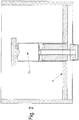
- FIG. 1 shows a liquid container 1, for example a flushing shaft for a sewer system, into which liquid flows through an inlet, not shown.
- the liquid is indicated with the liquid level 28.
- the liquid can drain through an outlet opening 2 on the underside of the liquid container 1 into a wastewater channel (not shown) behind it.
- the liquid level 28 In order to effect a flushing surge for flushing the sewage channel located behind the drain opening, the liquid level 28 must first be raised to a higher level, the so-called trigger level 29, so that a predetermined hydrostatic pressure is built up at the bottom of the liquid container 1. The drain opening is blocked until the trigger level 29 is reached and then released as suddenly as possible.
- the hydrostatic pressure is present at the drain opening, which corresponds to the trigger level 29 and thus determines as an initial condition how strong the rinsing surge produced is.
- the amount of liquid available for the flushing surge is influenced by the other two spatial dimensions of the liquid container 1.
- the drain opening 2 is optionally blocked and released by a drain valve 23, the drain valve member 23 having a valve member 15 which closes the drain opening 2 with a valve body 16.
- the drain opening 2 of the liquid container 1 serves as a valve seat 26 for the valve body 16.
- the valve member 15 itself is guided within a riser pipe 3 of the drain valve 23 along the pipe extension.
- the riser pipe 3 is arranged approximately perpendicular to the bottom 1 of the liquid container and is fixed against tilting by holding rods, not shown.
- the valve member 15 is in its initial position in its closed position. It is a matter of a low liquid level 28, as in FIG Figure 1 shown under the influence of gravity in the valve seat 26 formed by the drain opening 2 and thus seals the drain opening 2.
- the valve member 15 is made of a material which has a higher density than the liquid present in the liquid container 1, so that the valve member 15 itself cannot float in the liquid.
- valve member 15 with its valve body 16 is additionally pressed into the closed position by the hydrostatic pressure present in the liquid container 1 in the region of the outlet opening 2.
- the valve member 15 is float-controlled by means of a float 11, the shimmer 11 being able to float in the liquid present in the liquid container 1.
- the float 11 is arranged on a valve stem 17 of the valve member 15, at least partially surrounding the valve stem 17.
- the float 11 has a longitudinal bore 12, in which the valve stem 17 is accommodated so that it can move relative to the float 11.
- Both the valve member 15 and the float 11 are approximately rotationally symmetrical components, so that the arrangement of the float 11 on the valve member 15 can be described as coaxial.
- the float 11 is arranged on the valve member 15 so as to be longitudinally displaceable between the shut-off element 16 and a driver stop 19 for the float.
- valve member 15 and the float 11 already protrude into the riser pipe 3 in the closed position of the valve member 15, the float 11 with its outer surface 14 being supported on the inside of the riser pipe 3 and thus for guiding both the float 11 and the coaxially arranged valve member 15 provides.
- the riser pipe 3 has a pipe section 5 which has an inlet opening 4 on the underside.
- the inlet opening 4 can be designed as an open end face of the pipe section 5 which is executed for the outlet opening 2.
- the inside of the riser pipe 3 is in liquid communication with the liquid container 1 via the inlet opening 4.
- a vent opening 6 is provided, which is closed in the locked position by a shut-off element 8 designed as a cover.
- the shut-off element is guided by a guide 7 in such a way that it lies in the locked position under the influence of gravity on the upper side of the raw section 5 and thereby closes the vent opening 6 with a dome-shaped sealing section 10.
- the shut-off element 8 has a float section 9 which is wider than the sealing section 10. Furthermore, the shut-off element 8 is made of a material which is floatable in the liquid. That is, the material of the float section 9 has a lower density than the liquid in the liquid container 1. In any case, the shut-off element 8 is designed as a float or float. Therefore, variants are also conceivable in which the shut-off element 8 is made of a material with a higher density than the liquid in the liquid container 1, but the design of the shut-off element 8 as a floating body ensures floating in the liquid. Cup-shaped configurations or hollow configurations are conceivable here, in which the recesses do not come into contact with the liquid level rising in the liquid container 1 during normal operation.
- the shut-off element 8 in interaction with the ventilation opening 6, in particular with the guide 7 and the dome-shaped sealing section 10, forms a ventilation device 24 for the riser pipe 3.
- a ventilation device 24 for the riser pipe 3.
- differently designed ventilation devices 24 are also conceivable.
- an air cushion 27 adjoins the ventilation opening 6, which is enclosed within the riser pipe 3 when the liquid level 28 rises in the liquid container 1. Liquid then lies on the underside of the pipe section 5 at the inlet opening 4 and can enter the riser pipe 3 until a pressure equilibrium is established between the internal pressure of the air cushion and the hydrostatic pressure present in the region of the inlet opening 4.
- a space 31 adjoins the ventilation opening 6 and is limited by the shut-off element 8, the pipe section 5 and the liquid level 28 present at the inlet opening 4. That is, for example, in the Figure 2 shown.
- the liquid level rising in the riser pipe 3 until the pressure equilibrium is reached can already ensure that the float 11 partially floats and rises within the riser pipe, but without attacking the driver stop 19 of the valve member 15 and thus already opening the valve member 15.
- the liquid level 28 can then continue to rise until it reaches the trigger level 29, which in the Figure 3 is drawn.
- shut-off element 8 floats in the liquid and thus opens the ventilation opening 6, which suddenly releases the enclosed and underpressure air cushion 27 from the riser pipe.
- this drain opening 2 is suddenly released by the valve member 15, so that, as in FIG Figure 5 shown, the liquid 34 can escape in the form of a flushing surge through the outlet opening 2 from the liquid container 1.
- the liquid level 28 then drops again in the liquid container 1 and releases the shut-off element 8, so that it falls back into the blocking position due to the guide 7, in which the ventilation opening 6 of the riser pipe 3 is blocked. Due to the liquid column in the riser pipe 3, the float 11 remains in the open position within the riser pipe 3 until enough liquid has drained from the liquid container 1 that the liquid level 28 releases the inlet opening 4 of the riser pipe again, so that ambient air enters the riser pipe 3 can occur and thus the liquid level within the riser 3 drops again. As soon as the liquid can drain down from the riser pipe 3, the float 11 also falls together with the valve member 15 into the lower closed position in order to close the drain opening 2 of the liquid container 1.
- a pressure compensation device 25 is provided on the drain valve, the purpose of which is to produce a pressure balance between the upper side of the valve member 15 facing the vent opening 6 and the underside of the valve member 15 facing the drain opening 2.
- a pressure compensation channel 18 is formed in the valve member 15 in the form of a longitudinal bore, which extends from the underside of the valve body 16 to the top of the driver stop 19.
- the pressure compensation duct 18 is basically closed by a check valve 33, which is guided by a seal 20 lying in the longitudinal bore of the pressure compensation duct 18 and a seal 20 on the inside of the pipe section 5 Disk section 21 is formed.
- the seal 20 has a sealing cap 22 which lies in the longitudinal bore of the pressure compensation channel and closes it in a sealing manner.
- the passage direction 30 of the check valve 33 is directed from the drain opening 2 to the vent opening 6. This has the effect that the air cushion 27 enclosed in the riser pipe 3 cannot escape through the pressure equalization channel 18, since otherwise liquid could enter the riser pipe 3 through the inlet opening 4 before the shut-off element 8 opens the vent opening 6.
- a bridging section 32 is attached to the float 11, which bridges opposite the upper end of the float 11 and which can receive the driver stop 19 of the valve member 15.
- the bridging section 32 connects to a longitudinal bore 12 which is arranged centrally in the float 11 and which receives the valve stem 17 of the valve member 15.
- the bridging section 32 is formed so far back that when the driver stop 19 is received in the bridging section 32, the upper end of the float 11 can engage the disk section 21 of the seal 20, which protrudes radially with respect to the driver stop 19. It should be noted here that neither the driver stop 19 nor the disk section 21 lie sealingly on the inside of the pipe section 5, so that both the valve member 15 and the float 11 can move freely towards the ventilation opening 6.
- the check valve 33 can also open automatically before the bridging section 32 can engage the disk section 21. This is the case when there is a pressure drop in the forward direction 30 at the check valve 33 is applied, so that it is briefly raised from its closed position into an open position under the influence of the pressure drop and falls back into the closed position after the pressure has been equalized.
- FIGS. 6 and 7 show an embodiment of the invention, which differs from that in the Figures 1 - 5
- Liquid container shown essentially differs in that the float 11 and the valve member 15 are formed as a one-piece valve member 37.
- the valve member 37 protrudes in the in Figure 6 Shown closed position shown in the riser pipe 3 and simultaneously closes the drain opening 2 of the liquid container 1 with its valve body 16.
- the liquid level 28 reaches the trigger level 29, as in FIG Figure 7 shown - liquid 34 enter through overflow openings 42 provided on the riser pipe 3 in an upper section 47 of the riser pipe 3, so that a float 38 located therein can float.
- the float 38 is designed as a floating body in the form of a cup which is open in the direction of the ventilation opening 6 and in which an air cushion 27 is enclosed in the upper section 47 when liquid 34 enters.
- the float 38 is connected to the shut-off element 8 by means of the guide 7, so that the floating float 38 simultaneously raises the shut-off element 8 and thus actuates the ventilation device 24 and opens the ventilation opening 6.
- the air 35 enclosed in the space 31 of the riser pipe 3 can then escape through the ventilation opening 6, so that the internal level 40 present in the riser pipe 3 rises abruptly and the valve member 37 into the Open position.
- the liquid 34 enters the riser pipe 3 through the inlet opening 4.
- a locking bar 41 is additionally provided on the guide 7, which is arranged within the space 31 of the riser pipe 3 and prevents the guide 7 from disengaging from the riser pipe 3 by positive locking ,
- the density is so great that there is a sufficient sealing effect between the valve body 16 and the valve seat 26 in the closed position due to the weight of the valve member 37.
- the density of the valve member 37 is small enough that the valve member 37 is reliably transferred to the open position when the internal level 40 is increased.
- the drain valve 36 with the riser pipe 3 can also be inserted as a retrofit part in an already existing liquid container 1.
- the emptying valve 36 can be inserted into the liquid container 1 during a standing installation and supported on the liquid container 1 with feet 45, for example three feet 45 evenly distributed over the circumference of the riser pipe 3.
- the riser pipe 3 is supported with its feet 45 on a shoulder 48 which is present in the liquid container 1 and which, for example, could be part of the valve seat 26 of a previously installed emptying valve.
- Centering bevels 46 can be provided on one or more of the feet 45 for an exact assembly of the riser pipe 3 with respect to the outlet opening 2, that is to say for a precisely fitting seat of the valve body 16 in the valve seat 26 of the liquid container 1. These centering bevels 46 cooperate with the shoulder 48 of the liquid container 1 in such a way that the riser pipe 3 automatically slides into the required installation position. The riser pipe 3 can then be secured against slipping out of the installation position by means of additional fastening means.
Claims (9)
- Récipient de liquide (1) servant à produire des curages à vague à l'aide d'une vanne de vidange (36) servant à bloquer une ouverture d'évacuation (2) du récipient de liquide (1) réalisé en tant que conduit de curage pour un système de canaux d'eaux usées et doté d'un tuyau montant (3) dans lequel un liquide peut monter, et d'un organe de vanne (37) réalisé en tant que flotteur (11), lequel organe de vanne flotte en cas d'entrée de liquide dans le tuyau montant (3) et monte de sa position de fermeture fermant l'ouverture d'évacuation (2) à une position d'ouverture, dans lequel un dispositif de ventilation (24) est prévu, lequel bloque et libère sélectivement une ouverture de ventilation (6) du tuyau montant (3), de sorte qu'un coussin d'air (27), qui se forme dans un espace (31) adjacent à l'ouverture de ventilation (6) à l'intérieur du tuyau montant (3), sorte du tuyau montant (3) et que du liquide puisse entrer dans le tuyau montant (3), dans lequel l'organe de vanne (37) est disposé au moins partiellement dans le tuyau montant (3), dans lequel le flotteur (11) est réalisé en tant que corps creux doté d'un espace intérieur de flotteur (44) qui est rempli au moins partiellement de lest (43) pour le réglage de la densité du flotteur (11), dans lequel ce remplissage partiel avec du lest (43) sert à adapter la densité du flotteur (11) de telle sorte que la densité soit d'une part suffisamment élevée pour qu'un effet d'étanchéité suffisant entre un corps de vanne (16) de l'organe de vanne (37) et un siège de vanne (26) formé par l'ouverture d'évacuation (2) dans la position de fermeture soit présent en raison de la force de gravité de l'organe de vanne (37), et que d'autre part la densité de l'organe de vanne (37) soit suffisamment faible pour que l'organe de vanne (37) soit transféré de manière fiable à la position d'ouverture en cas d'élévation du niveau interne (40), le dispositif de ventilation (24) comprenant un élément d'arrêt (8) qui ferme l'ouverture de ventilation (6) dans la position de blocage et est relié à un autre flotteur (38) disposé dans une partie supérieure (47) du tuyau montant (3) dotée d'ouvertures de trop-plein (42), de sorte que du liquide (34) puisse entrer dans la partie supérieure (47) du tuyau montant (3) et permettre à l'autre flotteur (38) de flotter, dans lequel le flotteur (38) est réalisé en tant que corps flottant sous forme de cuvette ouverte en direction de l'ouverture de ventilation (6), cuvette dans laquelle un coussin d'air (27) peut être contenu en cas d'entrée de liquide (34) dans la partie supérieure (47) du tuyau montant (3), dans lequel le flotteur (38) est relié à l'élément d'arrêt (8) au moyen d'un guide (7), de sorte que le flotteur (38) flottant soulève simultanément l'élément d'arrêt (8) et actionne par conséquent le dispositif de ventilation (24) et libère l'ouverture de ventilation (6).
- Récipient de liquide (1) selon la revendication 1, caractérisé en ce que le flotteur (11) pénètre, dans la position de fermeture, dans l'espace (31) à l'intérieur du tuyau montant (3) .
- Récipient de liquide (1) selon l'une des revendications précédentes, caractérisé en ce que le dispositif de ventilation (24) libère l'ouverture de ventilation (6) en fonction d'un niveau de liquide (28) entourant le tuyau montant (3) .
- Récipient de liquide (1) selon l'une des revendications précédentes, caractérisé en ce que le dispositif de ventilation (24) est commandé par flotteur.
- Récipient de liquide (1) selon l'une des revendications précédentes, caractérisé en ce que l'élément d'arrêt (8) comprend une partie d'étanchéité (10) à l'aide de laquelle l'ouverture de ventilation (6) peut être fermée.
- Récipient de liquide (1) selon l'une des revendications précédentes, caractérisé en ce que le guide (7) est prévu au niveau du tuyau montant (3) ou de l'élément d'arrêt (8).
- Procédé de production d'une vague de curage pour un système de canaux d'eaux usées, dans lequel un niveau de liquide (28) dans un récipient de liquide (1) réalisé en tant que conduit de curage pour le système de canaux d'eaux usées est élevé par admission d'un liquide (34) et une vanne de vidange (23, 36) du récipient de liquide (1) est ouverte lorsqu'un niveau de déclenchement (29) est atteint et un flotteur (11) prévu dans un tuyau montant (3) flotte lors de l'entrée de liquide (34) dans le tuyau montant (3) et s'y élève, afin d'ouvrir la vanne de vidange, dans lequel le flotteur (11) est réalisé en tant que corps creux doté d'un espace intérieur de flotteur (44) qui est rempli au moins partiellement de lest (43) pour le réglage de la densité du flotteur (11), dans lequel ce remplissage partiel avec du lest (43) sert à adapter la densité du flotteur (11) de telle sorte que la densité soit d'une part suffisamment élevée pour qu'un effet d'étanchéité suffisant entre un corps de vanne (16) de l'organe de vanne (37) et un siège de vanne (26) formé par l'ouverture d'évacuation (2) dans la position de fermeture soit présent en raison de la force de gravité de l'organe de vanne (37), et que d'autre part la densité de l'organe de vanne (37) soit suffisamment faible pour que l'organe de vanne (37) soit transféré de manière fiable à la position d'ouverture en cas d'élévation du niveau interne (40), dans lequel l'entrée du liquide dans le tuyau montant (3) est empêchée par un coussin d'air (27) entouré par le liquide dans celui-ci jusqu'à ce qu'un dispositif de ventilation (24) se déclenche lorsque le niveau de déclenchement (29) est atteint, afin de faire sortir le coussin d'air (27) du tuyau montant (3), dans lequel le dispositif de ventilation (24) est déclenché par flottaison d'un élément d'arrêt (8) et l'élément d'arrêt (8) est relié à un autre flotteur (38) disposé dans une partie supérieure (47) du tuyau montant (3) dotée d'ouvertures de trop-plein (42), de sorte que du liquide (34) puisse entrer dans la partie supérieure (47) du tuyau montant (3) et permettre à l'autre flotteur (38) de flotter, dans lequel l'autre flotteur (38) est réalisé en tant que corps flottant sous forme de cuvette ouverte en direction de l'ouverture de ventilation (6), cuvette dans laquelle un coussin d'air (27) peut être contenu en cas d'entrée de liquide (34) dans la partie supérieure (47) du tuyau montant (3), dans lequel l'autre flotteur (38) est relié à l'élément d'arrêt (8) au moyen d'un guide (7), de sorte que l'autre flotteur (38) flottant soulève simultanément l'élément d'arrêt (8) et actionne par conséquent le dispositif de ventilation (24) et libère l'ouverture de ventilation (6).
- Procédé selon la revendication 7, caractérisé en ce qu'après le déclenchement du dispositif de ventilation (24), le flotteur (11) flotte dans le tuyau montant (3) et s'élève jusqu'à ce qu'il vienne en prise avec un organe de vanne (15) de la vanne de vidange et le soulève de la position de fermeture à la position d'ouverture, ou en ce que le flotteur (11) réalisé en tant qu'organe de vanne (37) flotte après le déclenchement du dispositif de ventilation (24) et monte en l'occurrence de la position de fermeture à la position d'ouverture.
- Procédé selon l'une des revendications précédentes 7 et 8, caractérisé en ce qu'un débit de curage et/ou l'intervalle de curage sont réglés par réglage du dispositif de vidange (24), en particulier par modification des propriétés physiques et/ou géométriques de l'élément d'arrêt (8) .
Priority Applications (1)
| Application Number | Priority Date | Filing Date | Title |
|---|---|---|---|
| PL17156476T PL3219864T3 (pl) | 2016-03-17 | 2017-02-16 | Zbiornik na ciecz z zaworem opróżniającym oraz odpowiedni sposób generowania fali spiętrzenia przepłukującego |
Applications Claiming Priority (1)
| Application Number | Priority Date | Filing Date | Title |
|---|---|---|---|
| DE102016104936.0A DE102016104936A1 (de) | 2016-03-17 | 2016-03-17 | Entleerungsventil für einen Flüssigkeitsbehälter, Flüssigkeitsbehälter zum Erzeugen eines Spülschwalls und Verfahren zum Erzeugen eines Spülschwalls |
Publications (2)
| Publication Number | Publication Date |
|---|---|
| EP3219864A1 EP3219864A1 (fr) | 2017-09-20 |
| EP3219864B1 true EP3219864B1 (fr) | 2020-02-26 |
Family
ID=58098475
Family Applications (1)
| Application Number | Title | Priority Date | Filing Date |
|---|---|---|---|
| EP17156476.8A Active EP3219864B1 (fr) | 2016-03-17 | 2017-02-16 | Récipient de liquide comprenant une soupape die vidange et utilisation correspondante pour produire une vague de rinçage |
Country Status (3)
| Country | Link |
|---|---|
| EP (1) | EP3219864B1 (fr) |
| DE (1) | DE102016104936A1 (fr) |
| PL (1) | PL3219864T3 (fr) |
Citations (1)
| Publication number | Priority date | Publication date | Assignee | Title |
|---|---|---|---|---|
| DE2154934A1 (de) * | 1970-11-26 | 1972-06-15 | Aktiebolaget Electrolux, Stockholm | Ventilanordnung an der Auslaßöffnung eines Flüssigkeitsbehälters |
Family Cites Families (8)
| Publication number | Priority date | Publication date | Assignee | Title |
|---|---|---|---|---|
| US3987501A (en) * | 1974-06-17 | 1976-10-26 | Producers Specialty & Mfg. Co., Inc. | Toilet flush assembly |
| DE3915076A1 (de) * | 1989-05-09 | 1990-11-15 | Alloy Tech Ag | Vorrichtung an einem fluessigkeitsspeicherraum zum selbsttaetigen spuelen des leergelaufenen speicherraumes |
| DE29604004U1 (de) * | 1996-03-05 | 1997-07-10 | Bionik Gmbh Innovative Technik | Vorrichtung zum stoßweisen Entleeren eines Flüssigkeitsstauraumes, insbesondere in einem Kanalisationsnetz |
| DE19930346C2 (de) | 1999-07-02 | 2002-11-14 | Klaus Ulrich Giehl | Kanalspüler |
| DE10010836C5 (de) | 2000-03-09 | 2014-06-12 | Lothar Liebau | Verfahren zur Schwallspülung eines Mischwasserkanals sowie Vorrichtung hierzu |
| DE20207805U1 (de) * | 2002-04-27 | 2002-09-05 | Preiss Peter | Einrichtung zur Spülung von Anschlusskanälen, Grund- und Sammelleitungen |
| DK1669500T3 (da) | 2004-12-08 | 2011-01-24 | Steinhardt Gmbh | Skvulpe-skylleindretning til rensning af kanaler, hvilken skvulpe-skylleindretning har en tætning |
| DE202012006401U1 (de) | 2012-07-04 | 2012-10-08 | Biogest Ag | Kanalspüler zur Reinigung eines Ablaufkanals für Regen- oder Mischwasser in einem Spülschacht |
-
2016
- 2016-03-17 DE DE102016104936.0A patent/DE102016104936A1/de not_active Withdrawn
-
2017
- 2017-02-16 EP EP17156476.8A patent/EP3219864B1/fr active Active
- 2017-02-16 PL PL17156476T patent/PL3219864T3/pl unknown
Patent Citations (1)
| Publication number | Priority date | Publication date | Assignee | Title |
|---|---|---|---|---|
| DE2154934A1 (de) * | 1970-11-26 | 1972-06-15 | Aktiebolaget Electrolux, Stockholm | Ventilanordnung an der Auslaßöffnung eines Flüssigkeitsbehälters |
Also Published As
| Publication number | Publication date |
|---|---|
| DE102016104936A1 (de) | 2017-09-21 |
| EP3219864A1 (fr) | 2017-09-20 |
| PL3219864T3 (pl) | 2020-09-07 |
Similar Documents
| Publication | Publication Date | Title |
|---|---|---|
| CH663045A5 (de) | Ablaufgarnitur fuer einen spuelkasten. | |
| EP0010310A2 (fr) | Soupape d'obturation pour le contrôle du niveau d'un liquide | |
| EP2865817A1 (fr) | Garniture d'écoulement pour une chasse d'eau | |
| DE3915076C2 (fr) | ||
| DE2520760A1 (de) | Ablaufventil fuer spuelkasten | |
| EP3263781B1 (fr) | Garniture d'entrée | |
| EP0083358A1 (fr) | Installation de remplissage automatique de cellules de batterie. | |
| EP3219864B1 (fr) | Récipient de liquide comprenant une soupape die vidange et utilisation correspondante pour produire une vague de rinçage | |
| DE2800556C3 (de) | Ventil zur Entlüftung und Belüftung insbesondere einer Abwasserleitung | |
| DE202012006401U1 (de) | Kanalspüler zur Reinigung eines Ablaufkanals für Regen- oder Mischwasser in einem Spülschacht | |
| DE3822555C2 (fr) | ||
| CH680741A5 (fr) | ||
| EP1475484B1 (fr) | Dispositif pour la chasse des égouts | |
| EP2505727B1 (fr) | Clapet de sortie pour une chasse d'eau | |
| DE2337853C2 (de) | Rückstau- und Geruchsverschluß für Flüssigkelten, Insbesondere Abwässer | |
| DE2612884B2 (de) | Absperrventil | |
| DE2601282A1 (de) | Vorrichtung zum entleeren und selbsttaetigen fuellen eines wasserspeichers, insbesondere toilettenspuelkasten | |
| DE60302619T2 (de) | Automatische Absperrvorrichtung eines Durchflusskanals | |
| DE4425244C1 (de) | Ventil zur Ent- und Belüftung insbesondere einer Abwasserleitung | |
| DE4137768C1 (en) | Automatic hoist with downwards open bell - has outlet tube, whose top end retains movably top-open float pot | |
| DE2154934A1 (de) | Ventilanordnung an der Auslaßöffnung eines Flüssigkeitsbehälters | |
| EP0619131B1 (fr) | Séparateur de liquide léger avec fermeture automatique | |
| EP4095324A1 (fr) | Système de rinçage | |
| DE2521928C2 (de) | Hilfsgesteuertes Schwimmerventil | |
| DE102010011366A1 (de) | Vorrichtung zur Befüllung von Speicherbehältern mit mehreren Schwimmerventilen |
Legal Events
| Date | Code | Title | Description |
|---|---|---|---|
| PUAI | Public reference made under article 153(3) epc to a published international application that has entered the european phase |
Free format text: ORIGINAL CODE: 0009012 |
|
| STAA | Information on the status of an ep patent application or granted ep patent |
Free format text: STATUS: THE APPLICATION HAS BEEN PUBLISHED |
|
| AK | Designated contracting states |
Kind code of ref document: A1 Designated state(s): AL AT BE BG CH CY CZ DE DK EE ES FI FR GB GR HR HU IE IS IT LI LT LU LV MC MK MT NL NO PL PT RO RS SE SI SK SM TR |
|
| AX | Request for extension of the european patent |
Extension state: BA ME |
|
| STAA | Information on the status of an ep patent application or granted ep patent |
Free format text: STATUS: REQUEST FOR EXAMINATION WAS MADE |
|
| 17P | Request for examination filed |
Effective date: 20171110 |
|
| RBV | Designated contracting states (corrected) |
Designated state(s): AL AT BE BG CH CY CZ DE DK EE ES FI FR GB GR HR HU IE IS IT LI LT LU LV MC MK MT NL NO PL PT RO RS SE SI SK SM TR |
|
| STAA | Information on the status of an ep patent application or granted ep patent |
Free format text: STATUS: EXAMINATION IS IN PROGRESS |
|
| 17Q | First examination report despatched |
Effective date: 20180522 |
|
| GRAP | Despatch of communication of intention to grant a patent |
Free format text: ORIGINAL CODE: EPIDOSNIGR1 |
|
| STAA | Information on the status of an ep patent application or granted ep patent |
Free format text: STATUS: GRANT OF PATENT IS INTENDED |
|
| INTG | Intention to grant announced |
Effective date: 20191018 |
|
| GRAS | Grant fee paid |
Free format text: ORIGINAL CODE: EPIDOSNIGR3 |
|
| GRAA | (expected) grant |
Free format text: ORIGINAL CODE: 0009210 |
|
| STAA | Information on the status of an ep patent application or granted ep patent |
Free format text: STATUS: THE PATENT HAS BEEN GRANTED |
|
| AK | Designated contracting states |
Kind code of ref document: B1 Designated state(s): AL AT BE BG CH CY CZ DE DK EE ES FI FR GB GR HR HU IE IS IT LI LT LU LV MC MK MT NL NO PL PT RO RS SE SI SK SM TR |
|
| REG | Reference to a national code |
Ref country code: GB Ref legal event code: FG4D Free format text: NOT ENGLISH |
|
| REG | Reference to a national code |
Ref country code: CH Ref legal event code: EP |
|
| REG | Reference to a national code |
Ref country code: AT Ref legal event code: REF Ref document number: 1237774 Country of ref document: AT Kind code of ref document: T Effective date: 20200315 |
|
| REG | Reference to a national code |
Ref country code: IE Ref legal event code: FG4D Free format text: LANGUAGE OF EP DOCUMENT: GERMAN |
|
| REG | Reference to a national code |
Ref country code: DE Ref legal event code: R096 Ref document number: 502017003925 Country of ref document: DE |
|
| REG | Reference to a national code |
Ref country code: NL Ref legal event code: FP |
|
| PG25 | Lapsed in a contracting state [announced via postgrant information from national office to epo] |
Ref country code: FI Free format text: LAPSE BECAUSE OF FAILURE TO SUBMIT A TRANSLATION OF THE DESCRIPTION OR TO PAY THE FEE WITHIN THE PRESCRIBED TIME-LIMIT Effective date: 20200226 Ref country code: RS Free format text: LAPSE BECAUSE OF FAILURE TO SUBMIT A TRANSLATION OF THE DESCRIPTION OR TO PAY THE FEE WITHIN THE PRESCRIBED TIME-LIMIT Effective date: 20200226 Ref country code: NO Free format text: LAPSE BECAUSE OF FAILURE TO SUBMIT A TRANSLATION OF THE DESCRIPTION OR TO PAY THE FEE WITHIN THE PRESCRIBED TIME-LIMIT Effective date: 20200526 |
|
| REG | Reference to a national code |
Ref country code: LT Ref legal event code: MG4D |
|
| PG25 | Lapsed in a contracting state [announced via postgrant information from national office to epo] |
Ref country code: BG Free format text: LAPSE BECAUSE OF FAILURE TO SUBMIT A TRANSLATION OF THE DESCRIPTION OR TO PAY THE FEE WITHIN THE PRESCRIBED TIME-LIMIT Effective date: 20200526 Ref country code: IS Free format text: LAPSE BECAUSE OF FAILURE TO SUBMIT A TRANSLATION OF THE DESCRIPTION OR TO PAY THE FEE WITHIN THE PRESCRIBED TIME-LIMIT Effective date: 20200626 Ref country code: LV Free format text: LAPSE BECAUSE OF FAILURE TO SUBMIT A TRANSLATION OF THE DESCRIPTION OR TO PAY THE FEE WITHIN THE PRESCRIBED TIME-LIMIT Effective date: 20200226 Ref country code: SE Free format text: LAPSE BECAUSE OF FAILURE TO SUBMIT A TRANSLATION OF THE DESCRIPTION OR TO PAY THE FEE WITHIN THE PRESCRIBED TIME-LIMIT Effective date: 20200226 Ref country code: HR Free format text: LAPSE BECAUSE OF FAILURE TO SUBMIT A TRANSLATION OF THE DESCRIPTION OR TO PAY THE FEE WITHIN THE PRESCRIBED TIME-LIMIT Effective date: 20200226 Ref country code: GR Free format text: LAPSE BECAUSE OF FAILURE TO SUBMIT A TRANSLATION OF THE DESCRIPTION OR TO PAY THE FEE WITHIN THE PRESCRIBED TIME-LIMIT Effective date: 20200527 |
|
| PG25 | Lapsed in a contracting state [announced via postgrant information from national office to epo] |
Ref country code: SK Free format text: LAPSE BECAUSE OF FAILURE TO SUBMIT A TRANSLATION OF THE DESCRIPTION OR TO PAY THE FEE WITHIN THE PRESCRIBED TIME-LIMIT Effective date: 20200226 Ref country code: PT Free format text: LAPSE BECAUSE OF FAILURE TO SUBMIT A TRANSLATION OF THE DESCRIPTION OR TO PAY THE FEE WITHIN THE PRESCRIBED TIME-LIMIT Effective date: 20200719 Ref country code: DK Free format text: LAPSE BECAUSE OF FAILURE TO SUBMIT A TRANSLATION OF THE DESCRIPTION OR TO PAY THE FEE WITHIN THE PRESCRIBED TIME-LIMIT Effective date: 20200226 Ref country code: SM Free format text: LAPSE BECAUSE OF FAILURE TO SUBMIT A TRANSLATION OF THE DESCRIPTION OR TO PAY THE FEE WITHIN THE PRESCRIBED TIME-LIMIT Effective date: 20200226 Ref country code: EE Free format text: LAPSE BECAUSE OF FAILURE TO SUBMIT A TRANSLATION OF THE DESCRIPTION OR TO PAY THE FEE WITHIN THE PRESCRIBED TIME-LIMIT Effective date: 20200226 Ref country code: LT Free format text: LAPSE BECAUSE OF FAILURE TO SUBMIT A TRANSLATION OF THE DESCRIPTION OR TO PAY THE FEE WITHIN THE PRESCRIBED TIME-LIMIT Effective date: 20200226 Ref country code: RO Free format text: LAPSE BECAUSE OF FAILURE TO SUBMIT A TRANSLATION OF THE DESCRIPTION OR TO PAY THE FEE WITHIN THE PRESCRIBED TIME-LIMIT Effective date: 20200226 Ref country code: ES Free format text: LAPSE BECAUSE OF FAILURE TO SUBMIT A TRANSLATION OF THE DESCRIPTION OR TO PAY THE FEE WITHIN THE PRESCRIBED TIME-LIMIT Effective date: 20200226 Ref country code: CZ Free format text: LAPSE BECAUSE OF FAILURE TO SUBMIT A TRANSLATION OF THE DESCRIPTION OR TO PAY THE FEE WITHIN THE PRESCRIBED TIME-LIMIT Effective date: 20200226 |
|
| REG | Reference to a national code |
Ref country code: DE Ref legal event code: R097 Ref document number: 502017003925 Country of ref document: DE |
|
| PLBE | No opposition filed within time limit |
Free format text: ORIGINAL CODE: 0009261 |
|
| STAA | Information on the status of an ep patent application or granted ep patent |
Free format text: STATUS: NO OPPOSITION FILED WITHIN TIME LIMIT |
|
| PG25 | Lapsed in a contracting state [announced via postgrant information from national office to epo] |
Ref country code: IT Free format text: LAPSE BECAUSE OF FAILURE TO SUBMIT A TRANSLATION OF THE DESCRIPTION OR TO PAY THE FEE WITHIN THE PRESCRIBED TIME-LIMIT Effective date: 20200226 |
|
| 26N | No opposition filed |
Effective date: 20201127 |
|
| PG25 | Lapsed in a contracting state [announced via postgrant information from national office to epo] |
Ref country code: SI Free format text: LAPSE BECAUSE OF FAILURE TO SUBMIT A TRANSLATION OF THE DESCRIPTION OR TO PAY THE FEE WITHIN THE PRESCRIBED TIME-LIMIT Effective date: 20200226 |
|
| PG25 | Lapsed in a contracting state [announced via postgrant information from national office to epo] |
Ref country code: MC Free format text: LAPSE BECAUSE OF FAILURE TO SUBMIT A TRANSLATION OF THE DESCRIPTION OR TO PAY THE FEE WITHIN THE PRESCRIBED TIME-LIMIT Effective date: 20200226 |
|
| GBPC | Gb: european patent ceased through non-payment of renewal fee |
Effective date: 20210216 |
|
| PG25 | Lapsed in a contracting state [announced via postgrant information from national office to epo] |
Ref country code: CH Free format text: LAPSE BECAUSE OF NON-PAYMENT OF DUE FEES Effective date: 20210228 Ref country code: LI Free format text: LAPSE BECAUSE OF NON-PAYMENT OF DUE FEES Effective date: 20210228 Ref country code: LU Free format text: LAPSE BECAUSE OF NON-PAYMENT OF DUE FEES Effective date: 20210216 |
|
| PG25 | Lapsed in a contracting state [announced via postgrant information from national office to epo] |
Ref country code: GB Free format text: LAPSE BECAUSE OF NON-PAYMENT OF DUE FEES Effective date: 20210216 Ref country code: IE Free format text: LAPSE BECAUSE OF NON-PAYMENT OF DUE FEES Effective date: 20210216 |
|
| REG | Reference to a national code |
Ref country code: DE Ref legal event code: R081 Ref document number: 502017003925 Country of ref document: DE Owner name: P.V. BETONFERTIGTEILWERKE GMBH, DE Free format text: FORMER OWNER: GEBR. FASEL BETONWERK GMBH, 56472 NISTERAU, DE |
|
| PGFP | Annual fee paid to national office [announced via postgrant information from national office to epo] |
Ref country code: NL Payment date: 20220216 Year of fee payment: 6 Ref country code: FR Payment date: 20220216 Year of fee payment: 6 Ref country code: BE Payment date: 20220216 Year of fee payment: 6 |
|
| PGFP | Annual fee paid to national office [announced via postgrant information from national office to epo] |
Ref country code: AT Payment date: 20230217 Year of fee payment: 7 |
|
| PG25 | Lapsed in a contracting state [announced via postgrant information from national office to epo] |
Ref country code: HU Free format text: LAPSE BECAUSE OF FAILURE TO SUBMIT A TRANSLATION OF THE DESCRIPTION OR TO PAY THE FEE WITHIN THE PRESCRIBED TIME-LIMIT; INVALID AB INITIO Effective date: 20170216 |
|
| PGFP | Annual fee paid to national office [announced via postgrant information from national office to epo] |
Ref country code: PL Payment date: 20230202 Year of fee payment: 7 Ref country code: DE Payment date: 20230228 Year of fee payment: 7 |
|
| PG25 | Lapsed in a contracting state [announced via postgrant information from national office to epo] |
Ref country code: CY Free format text: LAPSE BECAUSE OF FAILURE TO SUBMIT A TRANSLATION OF THE DESCRIPTION OR TO PAY THE FEE WITHIN THE PRESCRIBED TIME-LIMIT Effective date: 20200226 |
|
| P01 | Opt-out of the competence of the unified patent court (upc) registered |
Effective date: 20230530 |
|
| REG | Reference to a national code |
Ref country code: NL Ref legal event code: MM Effective date: 20230301 |
|
| REG | Reference to a national code |
Ref country code: BE Ref legal event code: MM Effective date: 20230228 |
|
| PG25 | Lapsed in a contracting state [announced via postgrant information from national office to epo] |
Ref country code: NL Free format text: LAPSE BECAUSE OF NON-PAYMENT OF DUE FEES Effective date: 20230301 |
|
| PG25 | Lapsed in a contracting state [announced via postgrant information from national office to epo] |
Ref country code: FR Free format text: LAPSE BECAUSE OF NON-PAYMENT OF DUE FEES Effective date: 20230228 |
|
| PG25 | Lapsed in a contracting state [announced via postgrant information from national office to epo] |
Ref country code: BE Free format text: LAPSE BECAUSE OF NON-PAYMENT OF DUE FEES Effective date: 20230228 |
|
| REG | Reference to a national code |
Ref country code: AT Ref legal event code: PC Ref document number: 1237774 Country of ref document: AT Kind code of ref document: T Owner name: P.V. BETONFERTIGTEILWERKE GMBH, DE Effective date: 20240212 |
|
| PGFP | Annual fee paid to national office [announced via postgrant information from national office to epo] |
Ref country code: AT Payment date: 20240220 Year of fee payment: 8 |