EP3219864B1 - Liquid recipient with valve and corresponding method of use producing a rinsing surge - Google Patents
Liquid recipient with valve and corresponding method of use producing a rinsing surge Download PDFInfo
- Publication number
- EP3219864B1 EP3219864B1 EP17156476.8A EP17156476A EP3219864B1 EP 3219864 B1 EP3219864 B1 EP 3219864B1 EP 17156476 A EP17156476 A EP 17156476A EP 3219864 B1 EP3219864 B1 EP 3219864B1
- Authority
- EP
- European Patent Office
- Prior art keywords
- float
- riser pipe
- liquid
- valve
- shut
- Prior art date
- Legal status (The legal status is an assumption and is not a legal conclusion. Google has not performed a legal analysis and makes no representation as to the accuracy of the status listed.)
- Active
Links
- 239000007788 liquid Substances 0.000 title claims description 148
- 238000000034 method Methods 0.000 title claims description 13
- 238000011010 flushing procedure Methods 0.000 claims description 47
- 238000007789 sealing Methods 0.000 claims description 16
- 238000007667 floating Methods 0.000 claims description 10
- 230000001960 triggered effect Effects 0.000 claims description 8
- 238000004519 manufacturing process Methods 0.000 claims description 4
- 230000001419 dependent effect Effects 0.000 claims description 2
- 206010016825 Flushing Diseases 0.000 claims 1
- 238000009423 ventilation Methods 0.000 description 27
- 239000003570 air Substances 0.000 description 16
- 238000013022 venting Methods 0.000 description 12
- 238000003860 storage Methods 0.000 description 11
- XLYOFNOQVPJJNP-UHFFFAOYSA-N water Substances O XLYOFNOQVPJJNP-UHFFFAOYSA-N 0.000 description 11
- 230000000630 rising effect Effects 0.000 description 7
- 230000002706 hydrostatic effect Effects 0.000 description 6
- 238000009434 installation Methods 0.000 description 5
- 239000002351 wastewater Substances 0.000 description 5
- 238000004140 cleaning Methods 0.000 description 4
- 239000000463 material Substances 0.000 description 4
- 239000010865 sewage Substances 0.000 description 4
- 230000000694 effects Effects 0.000 description 3
- 238000004891 communication Methods 0.000 description 2
- 230000007423 decrease Effects 0.000 description 2
- 238000013461 design Methods 0.000 description 2
- 230000005484 gravity Effects 0.000 description 2
- 238000005192 partition Methods 0.000 description 2
- 239000013049 sediment Substances 0.000 description 2
- 239000007787 solid Substances 0.000 description 2
- 239000002352 surface water Substances 0.000 description 2
- 238000011144 upstream manufacturing Methods 0.000 description 2
- 238000006424 Flood reaction Methods 0.000 description 1
- 238000009825 accumulation Methods 0.000 description 1
- 239000012080 ambient air Substances 0.000 description 1
- 238000013459 approach Methods 0.000 description 1
- 230000000903 blocking effect Effects 0.000 description 1
- 238000010276 construction Methods 0.000 description 1
- 238000006073 displacement reaction Methods 0.000 description 1
- 238000005516 engineering process Methods 0.000 description 1
- 239000012530 fluid Substances 0.000 description 1
- 230000003993 interaction Effects 0.000 description 1
- 238000012423 maintenance Methods 0.000 description 1
- 238000005259 measurement Methods 0.000 description 1
- 239000000203 mixture Substances 0.000 description 1
- 230000036316 preload Effects 0.000 description 1
- 239000000523 sample Substances 0.000 description 1
- 239000000126 substance Substances 0.000 description 1
- 238000012546 transfer Methods 0.000 description 1
- 238000002604 ultrasonography Methods 0.000 description 1
- 239000011345 viscous material Substances 0.000 description 1
Images


Classifications
-
- E—FIXED CONSTRUCTIONS
- E03—WATER SUPPLY; SEWERAGE
- E03F—SEWERS; CESSPOOLS
- E03F5/00—Sewerage structures
- E03F5/10—Collecting-tanks; Equalising-tanks for regulating the run-off; Laying-up basins
- E03F5/105—Accessories, e.g. flow regulators or cleaning devices
- E03F5/108—Cleaning devices providing a flushing surge
-
- E—FIXED CONSTRUCTIONS
- E03—WATER SUPPLY; SEWERAGE
- E03F—SEWERS; CESSPOOLS
- E03F9/00—Arrangements or fixed installations methods or devices for cleaning or clearing sewer pipes, e.g. by flushing
- E03F9/007—Devices providing a flushing surge
-
- E—FIXED CONSTRUCTIONS
- E03—WATER SUPPLY; SEWERAGE
- E03F—SEWERS; CESSPOOLS
- E03F2201/00—Details, devices or methods not otherwise provided for
- E03F2201/30—Devices providing a sequential discharge in sewer systems
Definitions
- the present invention relates to a liquid container for generating a flushing surge according to claim 1 and a method for generating a flushing surge according to claim 7 each for a sewer system.
- a method for flushing a mixed water channel and a device therefor are known, in which at least two successive, mutually lockable sections are provided in an underground sewer. First, the upstream section is partitioned off from the downstream section, and then, after reaching a predetermined dam level in the upstream section of the mixed water channel, the partition is abruptly released.
- motor-driven partition flaps are provided, which are actuated by a control and energy supply unit provided above ground. Furthermore, the level measurement for determining the accumulation height is carried out using ultrasound probes. This is how it works in the DE 100 10 836 A1 described concept technically very complex.
- a surge flushing device for cleaning sewers, also provided underground, within the sewer is from the EP 1 669 500 A1 known that is operated purely mechanically.
- a flushing plate operated by two lever arms of a parallel lever temporarily blocks the wastewater flow. In a lower shut-off position of the flushing plate, it is held in place by a closure so that the incoming wastewater can accumulate in front of the flushing plate.
- the flushing plate When a defined pent-up level is reached, the flushing plate is released via a control mechanism actuated by a headwater level in order to release the flushing surge.
- the control mechanism has a lock which is actuated by a lever provided with a float.
- a float is arranged in front of the flushing plate, which floats in the accumulated wastewater and thus actuates the parallel lever to transfer the flushing plate into an open position.
- the two devices described above have the disadvantage that they have to be arranged within the underground sewer, which makes maintenance and installation work very difficult.
- the damming height within the sewer is limited, so that the strength of the flushing surge is also subject to narrow limits and, depending on the length of the dammed-up channel section, a large amount of water may also be required to carry out the flushing surge.
- sewer flushing devices already exist in the prior art, which can be arranged above or outside the actual sewer. They are even operated above ground, preferably with surface water. Surface waters usually contain less solids and highly viscous components than the wastewater mixtures carried in the sewer itself.
- a channel washer which has a collecting tube for rinsing liquid and has a rinsing opening to the channel to be rinsed.
- a flood space is connected to the collecting space via a flood space opening, and a closure body closes the flushing opening and the flood space opening in its closed position. When the hallway floods, the closure body floats and releases it both openings free.
- the channel washer is characterized by the fact that the flood space is forcibly and abruptly filled with rinsing liquid and thus triggers the rinsing process even with a relatively low inflow.
- the aforementioned closure body is designed as a rubber or plastic ball, which must fit tightly into a seat formed by the flushing opening and the flood opening. Furthermore, the entire device has a total of three different floats and the structure is so complex that the manufacture of the sewer washer is relatively complex and cost-intensive.
- a device operating on a similar principle for flushing connecting ducts and base and collecting lines with a suction lifter or a drain valve is from the DE 202 07 805 U1 known.
- a sewer washer for cleaning a drainage channel for rain or mixed water in a flushing well known in which two separate floats are provided on a central support tube, and two separate shut-off devices for closing the drain opening, which are described in the form of a closure plate and a sealing element.
- An overflow pipe is also provided, through which water runs into a sealable filling zone when a certain flushing shaft level is exceeded, which gradually fills up.
- One of the two floats opens both shut-off devices at the same time when the water level in the filling zone rises.
- the sealing element is closed again by lowering the first float.
- the locking plate is closed again by the second float when the level in the flushing shaft rises, the second floating element being connected to the locking plate by a lever linkage.
- This device also incurs high investment costs, since the configuration with the lever linkage is relatively complex to manufacture.
- a device with a storage space for intermittent emptying of a liquid storage space in a sewer network is known.
- the storage space is through a Feed pipe fed with water, which emerges from the storage space through a drain pipe.
- a valve is located at the lower end of a piston rod which is axially aligned with the drain line and leads to a control cylinder.
- a control piston is arranged, which is movable in the control cylinder.
- the position of the main float in relation to the water level is such that the buoyancy force acting on it acts against the pressure of the hydraulic medium in the control cylinder like a kind of preload by a spring.
- the result of this is that when the valve opens, the control piston is suddenly pushed upwards.
- the hydraulic medium located in the upper chamber of the control cylinder can escape into the lower chamber via the control line. Due to the movement of the control piston together with the piston rod, the drain opening is suddenly opened so that the storage space empties like a surge.
- the valve When the water level drops, the valve is closed again by the control float via the linkage.
- the sinking of the main float following the sinking of the water level now causes via the control piston that the hydraulic medium contained in the lower chamber of the control cylinder flows back into the upper chamber.
- the adjustable closing valve allows this backflow and thus the sinking of the main float with the valve piston rod to be slowed down so that a certain amount of liquid can flow out or the storage space can be completely emptied before the drain opening is closed again by the valve.
- the desired maximum water level can be adjusted by adjusting the height of the main float and the control float.
- the DE 39 15 076 A1 relates to a device on a liquid storage space for automatic flushing of the empty storage space. As the liquid level rises, a rinsing chamber fills with storage liquid which can gush out through a rinsing opening.
- the invention is based on the object of specifying a further simplified and less expensive surge flushing device.
- the object is achieved by a liquid container according to claim 1 for generating surge flushes.
- the liquid container is designed as a flushing shaft for a sewer system, in particular for a sewer system.
- the drain valve has a riser pipe in which liquid can rise in order to shut off an outlet opening of the liquid container.
- a valve member designed as a float is accommodated in the riser pipe, which floats when liquid enters the riser pipe and rises from its closed position closing the drain opening into an open position.
- a ventilation device is provided, which either blocks or releases a ventilation opening of the riser pipe, so that an air cushion, which forms in a space adjacent to the ventilation opening within the riser pipe, is released from the riser pipe and liquid can suddenly enter the riser pipe.
- the valve member is at least partially arranged in the riser pipe.
- a venting device is provided in the riser pipe, which optionally blocks and releases a vent hole of the riser pipe, so that an air cushion, which forms in a space adjacent to the vent hole when the float floats, is released from the riser pipe and liquid can enter the riser pipe ,
- the float located therein floats and takes the valve member guided in the riser into the open position.
- the invention is based on the technical principle that the air cushion enclosed in the riser pipe is at least slightly overpressure in relation to the surroundings, so that when the ventilation device is opened, the air cushion can quickly escape from the riser pipe and the liquid level rising in the riser pipe together with the float located in the riser moves suddenly into the open position.
- valve member is actuated on the one hand by the liquid level as soon as only the ventilation opening of the riser pipe is released. This allows an extremely simple and robust construction of the drain valve.
- the float projects into the room in the closed position. This allows the float to be guided easily and safely in its actuation path.
- the venting device opens the venting opening as a function of a liquid level surrounding the riser pipe.
- the drain valve is arranged within the liquid container, which can be a flushing shaft, as a result of which the required installation space is significantly reduced.
- the riser pipe is not only in fluid communication with the liquid level in the liquid container. Rather, the liquid level rising in the liquid container can be used to actuate the ventilation device. In this way, the drain valve works automatically and reliably.
- the ventilation device is float-controlled. This is a very simple way to use the rising liquid level to operate the venting device. Compared to other forms of actuation, such as electrical or pneumatic actuation, such a design has significant cost advantages and works with greater reliability. According to a further embodiment of the invention it can be provided that the ventilation device has a shut-off element which closes the ventilation opening in the locked position. In this way, the ventilation device can be implemented with particularly simple means and works extremely reliably.
- the shut-off element has a sealing section with which the vent opening can be closed. This can improve the sealing function of the shut-off element for closing the ventilation opening, since the specially designed sealing section is adapted to the ventilation opening in order to close it in a targeted and reliable manner.
- a guide for the shut-off element is provided in the riser pipe.
- Such a guide has the purpose of guiding the shut-off element along its actuation path between the locked position and the release position, so that a more reliable function can be guaranteed.
- the valve body designed as a float is designed as a hollow body.
- the use of a hollow body has proven to be particularly advantageous. It can be provided here that the hollow body can be filled with ballast to adjust the density of the float, as a result of which the opening and closing behavior of the valve body designed as a float can be specifically adjusted.
- a method according to claim 7 for generating a flushing surge in a sewer system wherein a liquid level in a liquid container is raised by supplying a liquid and a drain valve of the liquid container is opened when a trigger level is reached and a float provided in the riser pipe when liquid enters and rises in the riser to open the drain valve.
- the method is characterized in that the entry of the liquid into the riser pipe is prevented by an air cushion enclosed therein by the liquid until a venting device triggers when the trigger level is reached in order to release the air cushion from the riser pipe.
- the venting device is triggered by the liquid rising in the liquid container by floating a shut-off element.
- the liquid level in the liquid container is used not only to generate the flushing surge, but also to control the surge flushing device.
- the float designed as a valve member floats up after the venting device has been triggered and abruptly rises from its closed position to its open position. In this way, not only is the actuation of the valve member triggered, but also the force required to move the valve member is provided by the floating of the float in the liquid level. This makes the proposed method primarily dependent on the liquid level in the liquid container and rising therein.
- a liquid inlet with a constant volume flow is provided in the liquid container and the method is carried out as described above. In this way, a periodically running gush flush can be achieved in order to ensure regular and reliable cleaning of the Ensure sewage system.
- the flushing quantity and / or the flushing interval can be set by adjusting the ventilation device.
- the flushing quantity and / or the flushing interval can be set here by changing the physical and / or geometric properties of the shut-off element.
- the Figures 1 to 5 show a liquid container not included in the invention.
- FIG. 1 shows a liquid container 1, for example a flushing shaft for a sewer system, into which liquid flows through an inlet, not shown.
- the liquid is indicated with the liquid level 28.
- the liquid can drain through an outlet opening 2 on the underside of the liquid container 1 into a wastewater channel (not shown) behind it.
- the liquid level 28 In order to effect a flushing surge for flushing the sewage channel located behind the drain opening, the liquid level 28 must first be raised to a higher level, the so-called trigger level 29, so that a predetermined hydrostatic pressure is built up at the bottom of the liquid container 1. The drain opening is blocked until the trigger level 29 is reached and then released as suddenly as possible.
- the hydrostatic pressure is present at the drain opening, which corresponds to the trigger level 29 and thus determines as an initial condition how strong the rinsing surge produced is.
- the amount of liquid available for the flushing surge is influenced by the other two spatial dimensions of the liquid container 1.
- the drain opening 2 is optionally blocked and released by a drain valve 23, the drain valve member 23 having a valve member 15 which closes the drain opening 2 with a valve body 16.
- the drain opening 2 of the liquid container 1 serves as a valve seat 26 for the valve body 16.
- the valve member 15 itself is guided within a riser pipe 3 of the drain valve 23 along the pipe extension.
- the riser pipe 3 is arranged approximately perpendicular to the bottom 1 of the liquid container and is fixed against tilting by holding rods, not shown.
- the valve member 15 is in its initial position in its closed position. It is a matter of a low liquid level 28, as in FIG Figure 1 shown under the influence of gravity in the valve seat 26 formed by the drain opening 2 and thus seals the drain opening 2.
- the valve member 15 is made of a material which has a higher density than the liquid present in the liquid container 1, so that the valve member 15 itself cannot float in the liquid.
- valve member 15 with its valve body 16 is additionally pressed into the closed position by the hydrostatic pressure present in the liquid container 1 in the region of the outlet opening 2.
- the valve member 15 is float-controlled by means of a float 11, the shimmer 11 being able to float in the liquid present in the liquid container 1.
- the float 11 is arranged on a valve stem 17 of the valve member 15, at least partially surrounding the valve stem 17.
- the float 11 has a longitudinal bore 12, in which the valve stem 17 is accommodated so that it can move relative to the float 11.
- Both the valve member 15 and the float 11 are approximately rotationally symmetrical components, so that the arrangement of the float 11 on the valve member 15 can be described as coaxial.
- the float 11 is arranged on the valve member 15 so as to be longitudinally displaceable between the shut-off element 16 and a driver stop 19 for the float.
- valve member 15 and the float 11 already protrude into the riser pipe 3 in the closed position of the valve member 15, the float 11 with its outer surface 14 being supported on the inside of the riser pipe 3 and thus for guiding both the float 11 and the coaxially arranged valve member 15 provides.
- the riser pipe 3 has a pipe section 5 which has an inlet opening 4 on the underside.
- the inlet opening 4 can be designed as an open end face of the pipe section 5 which is executed for the outlet opening 2.
- the inside of the riser pipe 3 is in liquid communication with the liquid container 1 via the inlet opening 4.
- a vent opening 6 is provided, which is closed in the locked position by a shut-off element 8 designed as a cover.
- the shut-off element is guided by a guide 7 in such a way that it lies in the locked position under the influence of gravity on the upper side of the raw section 5 and thereby closes the vent opening 6 with a dome-shaped sealing section 10.
- the shut-off element 8 has a float section 9 which is wider than the sealing section 10. Furthermore, the shut-off element 8 is made of a material which is floatable in the liquid. That is, the material of the float section 9 has a lower density than the liquid in the liquid container 1. In any case, the shut-off element 8 is designed as a float or float. Therefore, variants are also conceivable in which the shut-off element 8 is made of a material with a higher density than the liquid in the liquid container 1, but the design of the shut-off element 8 as a floating body ensures floating in the liquid. Cup-shaped configurations or hollow configurations are conceivable here, in which the recesses do not come into contact with the liquid level rising in the liquid container 1 during normal operation.
- the shut-off element 8 in interaction with the ventilation opening 6, in particular with the guide 7 and the dome-shaped sealing section 10, forms a ventilation device 24 for the riser pipe 3.
- a ventilation device 24 for the riser pipe 3.
- differently designed ventilation devices 24 are also conceivable.
- an air cushion 27 adjoins the ventilation opening 6, which is enclosed within the riser pipe 3 when the liquid level 28 rises in the liquid container 1. Liquid then lies on the underside of the pipe section 5 at the inlet opening 4 and can enter the riser pipe 3 until a pressure equilibrium is established between the internal pressure of the air cushion and the hydrostatic pressure present in the region of the inlet opening 4.
- a space 31 adjoins the ventilation opening 6 and is limited by the shut-off element 8, the pipe section 5 and the liquid level 28 present at the inlet opening 4. That is, for example, in the Figure 2 shown.
- the liquid level rising in the riser pipe 3 until the pressure equilibrium is reached can already ensure that the float 11 partially floats and rises within the riser pipe, but without attacking the driver stop 19 of the valve member 15 and thus already opening the valve member 15.
- the liquid level 28 can then continue to rise until it reaches the trigger level 29, which in the Figure 3 is drawn.
- shut-off element 8 floats in the liquid and thus opens the ventilation opening 6, which suddenly releases the enclosed and underpressure air cushion 27 from the riser pipe.
- this drain opening 2 is suddenly released by the valve member 15, so that, as in FIG Figure 5 shown, the liquid 34 can escape in the form of a flushing surge through the outlet opening 2 from the liquid container 1.
- the liquid level 28 then drops again in the liquid container 1 and releases the shut-off element 8, so that it falls back into the blocking position due to the guide 7, in which the ventilation opening 6 of the riser pipe 3 is blocked. Due to the liquid column in the riser pipe 3, the float 11 remains in the open position within the riser pipe 3 until enough liquid has drained from the liquid container 1 that the liquid level 28 releases the inlet opening 4 of the riser pipe again, so that ambient air enters the riser pipe 3 can occur and thus the liquid level within the riser 3 drops again. As soon as the liquid can drain down from the riser pipe 3, the float 11 also falls together with the valve member 15 into the lower closed position in order to close the drain opening 2 of the liquid container 1.
- a pressure compensation device 25 is provided on the drain valve, the purpose of which is to produce a pressure balance between the upper side of the valve member 15 facing the vent opening 6 and the underside of the valve member 15 facing the drain opening 2.
- a pressure compensation channel 18 is formed in the valve member 15 in the form of a longitudinal bore, which extends from the underside of the valve body 16 to the top of the driver stop 19.
- the pressure compensation duct 18 is basically closed by a check valve 33, which is guided by a seal 20 lying in the longitudinal bore of the pressure compensation duct 18 and a seal 20 on the inside of the pipe section 5 Disk section 21 is formed.
- the seal 20 has a sealing cap 22 which lies in the longitudinal bore of the pressure compensation channel and closes it in a sealing manner.
- the passage direction 30 of the check valve 33 is directed from the drain opening 2 to the vent opening 6. This has the effect that the air cushion 27 enclosed in the riser pipe 3 cannot escape through the pressure equalization channel 18, since otherwise liquid could enter the riser pipe 3 through the inlet opening 4 before the shut-off element 8 opens the vent opening 6.
- a bridging section 32 is attached to the float 11, which bridges opposite the upper end of the float 11 and which can receive the driver stop 19 of the valve member 15.
- the bridging section 32 connects to a longitudinal bore 12 which is arranged centrally in the float 11 and which receives the valve stem 17 of the valve member 15.
- the bridging section 32 is formed so far back that when the driver stop 19 is received in the bridging section 32, the upper end of the float 11 can engage the disk section 21 of the seal 20, which protrudes radially with respect to the driver stop 19. It should be noted here that neither the driver stop 19 nor the disk section 21 lie sealingly on the inside of the pipe section 5, so that both the valve member 15 and the float 11 can move freely towards the ventilation opening 6.
- the check valve 33 can also open automatically before the bridging section 32 can engage the disk section 21. This is the case when there is a pressure drop in the forward direction 30 at the check valve 33 is applied, so that it is briefly raised from its closed position into an open position under the influence of the pressure drop and falls back into the closed position after the pressure has been equalized.
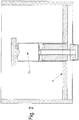
- FIGS. 6 and 7 show an embodiment of the invention, which differs from that in the Figures 1 - 5
- Liquid container shown essentially differs in that the float 11 and the valve member 15 are formed as a one-piece valve member 37.
- the valve member 37 protrudes in the in Figure 6 Shown closed position shown in the riser pipe 3 and simultaneously closes the drain opening 2 of the liquid container 1 with its valve body 16.
- the liquid level 28 reaches the trigger level 29, as in FIG Figure 7 shown - liquid 34 enter through overflow openings 42 provided on the riser pipe 3 in an upper section 47 of the riser pipe 3, so that a float 38 located therein can float.
- the float 38 is designed as a floating body in the form of a cup which is open in the direction of the ventilation opening 6 and in which an air cushion 27 is enclosed in the upper section 47 when liquid 34 enters.
- the float 38 is connected to the shut-off element 8 by means of the guide 7, so that the floating float 38 simultaneously raises the shut-off element 8 and thus actuates the ventilation device 24 and opens the ventilation opening 6.
- the air 35 enclosed in the space 31 of the riser pipe 3 can then escape through the ventilation opening 6, so that the internal level 40 present in the riser pipe 3 rises abruptly and the valve member 37 into the Open position.
- the liquid 34 enters the riser pipe 3 through the inlet opening 4.
- a locking bar 41 is additionally provided on the guide 7, which is arranged within the space 31 of the riser pipe 3 and prevents the guide 7 from disengaging from the riser pipe 3 by positive locking ,
- the density is so great that there is a sufficient sealing effect between the valve body 16 and the valve seat 26 in the closed position due to the weight of the valve member 37.
- the density of the valve member 37 is small enough that the valve member 37 is reliably transferred to the open position when the internal level 40 is increased.
- the drain valve 36 with the riser pipe 3 can also be inserted as a retrofit part in an already existing liquid container 1.
- the emptying valve 36 can be inserted into the liquid container 1 during a standing installation and supported on the liquid container 1 with feet 45, for example three feet 45 evenly distributed over the circumference of the riser pipe 3.
- the riser pipe 3 is supported with its feet 45 on a shoulder 48 which is present in the liquid container 1 and which, for example, could be part of the valve seat 26 of a previously installed emptying valve.
- Centering bevels 46 can be provided on one or more of the feet 45 for an exact assembly of the riser pipe 3 with respect to the outlet opening 2, that is to say for a precisely fitting seat of the valve body 16 in the valve seat 26 of the liquid container 1. These centering bevels 46 cooperate with the shoulder 48 of the liquid container 1 in such a way that the riser pipe 3 automatically slides into the required installation position. The riser pipe 3 can then be secured against slipping out of the installation position by means of additional fastening means.
Description
Die vorliegende Erfindung betrifft einen Flüssigkeitsbehälter zum Erzeugen eines Spülschwalls gemäß Anspruch 1 sowie ein Verfahren zum Erzeugen eines Spülschwalls gemäß Anspruch 7 jeweils für ein Abwasserkanalsystem.The present invention relates to a liquid container for generating a flushing surge according to
In Abwasserkanälen ist es häufig erforderlich, Reinigungsspülungen durchzuführen, da das von dem Abwasserkanal geführte Abwasser in der Regel nicht nur flüssige Stoffe enthält, sondern auch viskose Stoffe oder sogar Festkörper. Diese lagern sich insbesondere bei langsamen Fließgeschwindigkeiten am Boden des Abwasserkanals ab. Die so erzeugten Sedimente verringern mit der Zeit den effektiven Durchflussquerschnitt des Abwasserkanals, so dass der erreichbare Durchsatz an Abwasser verringert wird.In sewers, it is often necessary to carry out cleaning rinses, since the sewage led from the sewer generally contains not only liquid substances, but also viscous substances or even solids. These are deposited at the bottom of the sewer, particularly at slow flow speeds. The sediments produced in this way reduce the effective flow cross-section of the sewer over time, so that the achievable throughput of sewage is reduced.
Zur Beseitigung oder Verminderung dieses Problems gibt es verschiedene Ansätze in dem betreffenden technischen Gebiet, um Abwasserkanäle dauerhaft frei von größeren Sedimentablagerungen zu halten.There are various approaches in the technical field concerned to eliminate or reduce this problem in order to keep sewers permanently free of larger sediment deposits.
Neben manuell durchgeführte Spülungen, die nur mit großem Aufwand und damit verbundenen Kosten durchgeführt werden können, gibt es unterschiedliche technische Lösungen, mit deren Hilfe sich die ansonsten manuell durchzuführenden Tätigkeiten automatisieren lassen.In addition to manual flushing, which can only be carried out with great effort and the associated costs, there are various technical solutions that can be used to automate the otherwise manual tasks.
Aus der
Eine ebenfalls unterirdisch, innerhalb des Abwasserkanals vorgesehene Schwallspülvorrichtung zum Reinigen von Kanälen ist aus der
Bei Erreichen einer definiert aufgestauten Stauhöhe wird der Spülschild zur Freigabe des Spülschwalls über einen von einem Oberwasserstand betätigten Steuermechanismus entriegelt. Der Steuermechanismus weist eine Verriegelung auf, die von einem mit einem Schwimmer versehenen Hebel betätigt. Vor dem Spülschild ist ein Auftriebskörper angeordnet, welcher in dem aufgestauten Abwasser aufschwimmt und damit den Parallelhebel zum Überführen des Spülschildes in eine Öffnungsposition betätigt. Bei der vorstehend beschriebenen Schwallspülvorrichtung kann auf elektrische Komponenten verzichtet werden, und die Schwallspülvorrichtung kann als Ganzes innerhalb des Kanals unterirdisch angeordnet werden, so dass insgesamt der Aufbau gegenüber der zuerst beschriebenen Vorrichtung deutlich vereinfacht ist.When a defined pent-up level is reached, the flushing plate is released via a control mechanism actuated by a headwater level in order to release the flushing surge. The control mechanism has a lock which is actuated by a lever provided with a float. A float is arranged in front of the flushing plate, which floats in the accumulated wastewater and thus actuates the parallel lever to transfer the flushing plate into an open position. In the surge flushing device described above, electrical components can be dispensed with, and the surge flushing device as a whole can be arranged underground within the channel, so that overall the structure is significantly simplified compared to the device described first.
Die beiden zuvor beschriebenen Vorrichtungen haben dennoch den Nachteil, dass sie innerhalb des unterirdisch verlegten Abwasserkanals angeordnet werden müssen, was Wartungs- und Installationsarbeiten sehr erschwert. Außerdem ist die Stauhöhe innerhalb des Abwasserkanals begrenzt, so dass die Stärke des Spülschwalls ebenfalls engen Grenzen unterliegt und abhängig von der Länge des aufgestauten Kanalabschnitts auch eine große Wassermenge zur Durchführung des Spülschwalls erforderlich sein kann.However, the two devices described above have the disadvantage that they have to be arranged within the underground sewer, which makes maintenance and installation work very difficult. In addition, the damming height within the sewer is limited, so that the strength of the flushing surge is also subject to narrow limits and, depending on the length of the dammed-up channel section, a large amount of water may also be required to carry out the flushing surge.
Daher gibt es im Stand der Technik bereits Kanalspülvorrichtungen, die oberhalb beziehungsweise außerhalb des eigentlichen Abwasserkanals angeordnet seien können. Dabei werden diese sogar oberirdisch vorzugsweise mit Oberflächenwässern betätigt. Oberflächenwässer enthalten gewöhnlich weniger Feststoffe und hoch viskose Anteile in sich als die in dem Abwasserkanal selbst beförderten Abwassergemische.Therefore, sewer flushing devices already exist in the prior art, which can be arranged above or outside the actual sewer. They are even operated above ground, preferably with surface water. Surface waters usually contain less solids and highly viscous components than the wastewater mixtures carried in the sewer itself.
Hierzu ist aus der
Der vorgenannte Verschlusskörper ist dabei als Gummi- oder Kunststoffball ausgebildet, der genau in einen durch die Spülöffnung und die Flutöffnung gebildeten Sitz dichtend passen muss. Ferner weist die gesamte Vorrichtung insgesamt drei unterschiedliche Schwimmer auf und gestaltet sich vom Aufbau her derart komplex, dass die Herstellung des Kanalspülers relativ aufwendig und kostenintensiv ist.The aforementioned closure body is designed as a rubber or plastic ball, which must fit tightly into a seat formed by the flushing opening and the flood opening. Furthermore, the entire device has a total of three different floats and the structure is so complex that the manufacture of the sewer washer is relatively complex and cost-intensive.
Eine nach einem ähnlichen Prinzip arbeitende Einrichtung zur Spülung von Anschlusskanälen sowie Grund- und Sammelleitungen mit einem Saugheber oder einem Ablaufventil ist aus der
Alternativ dazu ist aus der
Auch bei dieser Vorrichtung fallen hohe Investitionskosten an, da die Ausgestaltung mit dem Hebelgestänge relativ aufwendig herzustellen ist.This device also incurs high investment costs, since the configuration with the lever linkage is relatively complex to manufacture.
Aus der
Der Hauptschwimmer ist in seiner Lage zu dem Wasserspiegel derart eingestellt, dass die auf ihn wirkende Auftriebskraft gegen den Druck des hydraulischen Mediums im Steuerzylinder wie eine Art Vorspannung durch eine Feder wirkt. Dies hat zur Folge, dass bei Öffnung des Ventils der Steuerkolben plötzlich nach oben gedrückt wird. Dabei kann das in der oberen Kammer des Steuerzylinders befindliche hydraulische Medium über die Steuerleitung in die untere Kammer ausweichen. Durch die Bewegung des Steuerkolbens samt Kolbenstange wird die Ablauföffnung plötzlich geöffnet, so dass der Stauraum sich schwallartig entleert.The position of the main float in relation to the water level is such that the buoyancy force acting on it acts against the pressure of the hydraulic medium in the control cylinder like a kind of preload by a spring. The result of this is that when the valve opens, the control piston is suddenly pushed upwards. The hydraulic medium located in the upper chamber of the control cylinder can escape into the lower chamber via the control line. Due to the movement of the control piston together with the piston rod, the drain opening is suddenly opened so that the storage space empties like a surge.
Beim Absinken des Wasserspiegels wird durch den Steuerschwimmer über das Gestänge das Ventil wieder geschlossen. Das dem Sinken des Wasserspiegels folgende Absinken des Hauptschwimmers bewirkt nun über den Steuerkolben, dass das in der unteren Kammer des Steuerzylinders enthaltene hydraulische Medium wieder in die obere Kammer strömt. Durch das einstellbare Schließventil kann dieses Zurückströmen und damit das Absinken des Hauptschwimmers mit der Ventilkolbenstange so verlangsamt werden, dass eine bestimmte Flüssigkeitsmenge ausfließen bzw. der Stauraum sich vollständig entleeren kann, bevor die Ablauföffnung durch das Ventil wieder geschlossen wird. Der gewünschte maximale Wasserspiegel kann durch Höhenverstellung des Hauptschwimmers sowie des Steuerschwimmers eingestellt werden.When the water level drops, the valve is closed again by the control float via the linkage. The sinking of the main float following the sinking of the water level now causes via the control piston that the hydraulic medium contained in the lower chamber of the control cylinder flows back into the upper chamber. The adjustable closing valve allows this backflow and thus the sinking of the main float with the valve piston rod to be slowed down so that a certain amount of liquid can flow out or the storage space can be completely emptied before the drain opening is closed again by the valve. The desired maximum water level can be adjusted by adjusting the height of the main float and the control float.
Die
Ausgehend von den zuvor beschriebenen Nachteilen liegt der Erfindung die Aufgabe zugrunde, eine weiter vereinfachte und kostengünstigere Schwallspülvorrichtung anzugeben.Starting from the disadvantages described above, the invention is based on the object of specifying a further simplified and less expensive surge flushing device.
Die Aufgabe wird gelöst durch einen Flüssigkeitsbehälter nach Anspruch 1 zur Erzeugung von Schwallspülungen.The object is achieved by a liquid container according to
Der Flüssigkeitsbehälter ist dabei als ein Spülschacht für ein Kanalsystem, insbesondere für ein Abwasserkanalsystem ausgebildet.The liquid container is designed as a flushing shaft for a sewer system, in particular for a sewer system.
Das Entleerungsventil weist zum Absperren einer Ablauföffnung des Flüssigkeitsbehälters ein Steigrohr auf, in welchem Flüssigkeit aufsteigen kann. In dem Steigrohr ist ein als Schwimmer ausgebildetes Ventilglied aufgenommen, welches bei Eintritt von Flüssigkeit in das Steigrohr aufschwimmt und aus seiner die Ablauföffnung verschließenden Schließstellung in eine Öffnungsstellung aufsteigt. Dabei ist eine Entlüftungsvorrichtung vorgesehen, welche eine Entlüftungsöffnung des Steigrohres wahlweise sperrt oder freigibt, so dass ein Luftpolster, welches sich in einem an die Entlüftungsöffnung angrenzendem Raum innerhalb des Steigrohres bildet, aus dem Steigrohr entlassen wird und Flüssigkeit schlagartig in das Steigrohr eintreten kann. Dabei ist das Ventilglied wenigstens teilweise in dem Steigrohr angeordnet.The drain valve has a riser pipe in which liquid can rise in order to shut off an outlet opening of the liquid container. A valve member designed as a float is accommodated in the riser pipe, which floats when liquid enters the riser pipe and rises from its closed position closing the drain opening into an open position. In this case, a ventilation device is provided, which either blocks or releases a ventilation opening of the riser pipe, so that an air cushion, which forms in a space adjacent to the ventilation opening within the riser pipe, is released from the riser pipe and liquid can suddenly enter the riser pipe. The valve member is at least partially arranged in the riser pipe.
Dabei ist im Steigrohr eine Entlüftungseinrichtung vorgesehen, welche eine Entlüftungsöffnung des Steigrohres wahlweise sperrt und freigibt, so dass ein Luftpolster, welches sich in einem an die Entlüftungsöffnung angrenzenden Raum bei Aufschwimmen des Schwimmers bildet, aus dem Steigrohr entlassen wird und Flüssigkeit in das Steigrohr eintreten kann.In this case, a venting device is provided in the riser pipe, which optionally blocks and releases a vent hole of the riser pipe, so that an air cushion, which forms in a space adjacent to the vent hole when the float floats, is released from the riser pipe and liquid can enter the riser pipe ,
Sobald die Flüssigkeit in das Steigrohr eintreten kann, schwimmt der darin befindliche Schwimmer auf und nimmt das in dem Steigrohr geführte Ventilglied mit in die Öffnungsstellung. Dabei liegt der Erfindung das technische Prinzip zu Grunde, dass das in dem Steigrohr eingeschlossene Luftpolster unter einem zumindest leichten Überdruck gegenüber der Umgebung steht, so dass beim Öffnen der Entlüftungseinrichtung das Luftpolster aus dem Steigrohr schnell entweichen kann und der in dem Steigrohr ansteigende Flüssigkeitsspiegel zusammen mit dem in dem Steigrohr befindlichen Schwimmer sich schlagartig in die Öffnungsstellung bewegt.As soon as the liquid can enter the riser, the float located therein floats and takes the valve member guided in the riser into the open position. The invention is based on the technical principle that the air cushion enclosed in the riser pipe is at least slightly overpressure in relation to the surroundings, so that when the ventilation device is opened, the air cushion can quickly escape from the riser pipe and the liquid level rising in the riser pipe together with the float located in the riser moves suddenly into the open position.
Vorteil dieser Vorrichtung ist insbesondere, dass das Ventilglied einerseits durch den Flüssigkeitspegel betätigt wird, sobald nur die Entlüftungsöffnung des Steigrohres freigegeben wird. Dies erlaubt einen äußerst einfachen und robusten Aufbau des Entleerungsventils.The advantage of this device is in particular that the valve member is actuated on the one hand by the liquid level as soon as only the ventilation opening of the riser pipe is released. This allows an extremely simple and robust construction of the drain valve.
In einer bevorzugten Ausführungsform kann vorgesehen sein, dass der Schwimmer in Schließstellung in den Raum hineinragt. Dies erlaubt eine einfache und sichere Führung des Schwimmers in dessen Betätigungsweg.In a preferred embodiment it can be provided that the float projects into the room in the closed position. This allows the float to be guided easily and safely in its actuation path.
Ferner kann vorgesehen sein, dass die Entlüftungseinrichtung in Abhängigkeit von einem das Steigrohr umgebenden Flüssigkeitspegel die Entlüftungsöffnung freigibt. Hierbei kann insbesondere vorgesehen sein, dass das Entleerungsventil innerhalb des Flüssigkeitsbehälters, der ein Spülschacht sein kann, angeordnet wird, wodurch der erforderliche Bauraum deutlich verringert wird. Hierbei steht das Steigrohr nicht nur in Fluidverbindung mit dem Flüssigkeitspegel in dem Flüssigkeitsbehälter. Vielmehr kann der in dem Flüssigkeitsbehälter ansteigende Flüssigkeitspegel dazu verwendet werden, die Entlüftungseinrichtung zu betätigen. Auf diese Weise funktioniert das Entleerungsventil selbsttätig und zuverlässig.It can further be provided that the venting device opens the venting opening as a function of a liquid level surrounding the riser pipe. In this case, it can be provided in particular that the drain valve is arranged within the liquid container, which can be a flushing shaft, as a result of which the required installation space is significantly reduced. Here, the riser pipe is not only in fluid communication with the liquid level in the liquid container. Rather, the liquid level rising in the liquid container can be used to actuate the ventilation device. In this way, the drain valve works automatically and reliably.
Erfindungsgemäss ist die Entlüftungseinrichtung schwimmergesteuert. Dies ist eine sehr einfache Möglichkeit, den ansteigenden Flüssigkeitspegel dazu zu nutzen, die Entlüftungseinrichtung zu betätigen. Gegenüber anderen Betätigungsformen, wie etwa eine elektrische oder pneumatische Betätigung, weist eine solche Gestaltung deutliche Kostenvorteile auf und funktioniert mit einer höheren Zuverlässigkeit. Gemäß einer weiteren Ausgestaltung der Erfindung kann vorgesehen sein, dass die Entlüftungseinrichtung ein Absperrelement aufweist, das in Sperrstellung die Entlüftungsöffnung verschließt. Auf diese Weise ist die Entlüftungseinrichtung mit besonders einfachen Mitteln umzusetzen und funktioniert äußerst zuverlässig.According to the invention, the ventilation device is float-controlled. This is a very simple way to use the rising liquid level to operate the venting device. Compared to other forms of actuation, such as electrical or pneumatic actuation, such a design has significant cost advantages and works with greater reliability. According to a further embodiment of the invention it can be provided that the ventilation device has a shut-off element which closes the ventilation opening in the locked position. In this way, the ventilation device can be implemented with particularly simple means and works extremely reliably.
Es kann ferner vorgesehen sein, dass das Absperrelement einen Dichtabschnitt aufweist, mit welchem die Entlüftungsöffnung verschließbar ist. Dies kann die Dichtfunktion des Absperrelementes zum Verschließen der Entlüftungsöffnung verbessern, da der speziell ausgebildete Dichtabschnitt auf die Entlüftungsöffnung angepasst ist, um diese gezielt und zuverlässig zu verschließen.It can further be provided that the shut-off element has a sealing section with which the vent opening can be closed. This can improve the sealing function of the shut-off element for closing the ventilation opening, since the specially designed sealing section is adapted to the ventilation opening in order to close it in a targeted and reliable manner.
Erfindungsgemäss ist im Steigrohr eine Führung für das Absperrelement vorgesehen. Eine solche Führung hat den Zweck, das Absperrelement entlang seines Betätigungsweges zwischen der Sperrstellung und der Freigabestellung zu führen, so dass eine zuverlässigere Funktion gewährleistet werden kann.According to the invention, a guide for the shut-off element is provided in the riser pipe. Such a guide has the purpose of guiding the shut-off element along its actuation path between the locked position and the release position, so that a more reliable function can be guaranteed.
Erfindungsgemäss ist der als Schwimmer ausgebildete Ventilkörper als Hohlkörper ausgebildet. Herstellungstechnisch hat sich die Verwendung eines Hohlkörpers als besonders vorteilhaft herausgestellt. So kann hierbei vorgesehen sein, dass der Hohlkörper zur Einstellung der Dichte des Schwimmers mit Ballast befüllbar ist, wodurch sich das Öffnungs- und Schließverhalten des als Schwimmer ausgebildeten Ventilkörpers gezielt einstellen lässt.According to the invention, the valve body designed as a float is designed as a hollow body. In terms of production technology, the use of a hollow body has proven to be particularly advantageous. It can be provided here that the hollow body can be filled with ballast to adjust the density of the float, as a result of which the opening and closing behavior of the valve body designed as a float can be specifically adjusted.
Die oben stehende Aufgabe wird ferner durch ein Verfahren nach Anspruch 7 zum Erzeugen eines Spülschwalls in einem Abwasserkanalsystem gelöst, wobei ein Flüssigkeitsspiegel in einem Flüssigkeitsbehälter durch Zulauf einer Flüssigkeit angehoben und ein Entleerungsventil des Flüssigkeitsbehälters bei Erreichen eines Auslösepegels geöffnet wird und ein in dem Steigrohr vorgesehener Schwimmer bei Eintritt von Flüssigkeit in dem Steigrohr aufschwimmt und darin aufsteigt, um das Entleerungsventil zu öffnen.The above object is further achieved by a method according to claim 7 for generating a flushing surge in a sewer system, wherein a liquid level in a liquid container is raised by supplying a liquid and a drain valve of the liquid container is opened when a trigger level is reached and a float provided in the riser pipe when liquid enters and rises in the riser to open the drain valve.
Erfindungsgemäß zeichnet sich das Verfahren dadurch aus, dass der Eintritt der Flüssigkeit in das Steigrohr durch ein darin von der Flüssigkeit eingeschlossenes Luftpolster so lange verhindert wird, bis eine Entlüftungseinrichtung bei Erreichen des Auslösepegels auslöst, um das Luftpolster aus dem Steigrohr zu entlassen.According to the invention, the method is characterized in that the entry of the liquid into the riser pipe is prevented by an air cushion enclosed therein by the liquid until a venting device triggers when the trigger level is reached in order to release the air cushion from the riser pipe.
Im Vergleich zu den aus dem Stand der Technik bekannten Vorrichtungen und Verfahren zum Erzeugen eines Spülschwalls hat sich dieses Verfahren als besonders einfach und dabei zuverlässig herausgestellt.In comparison to the devices and methods for generating a flushing surge known from the prior art, this method has proven to be particularly simple and reliable.
Erfindungsgemäß ist vorgesehen, dass die Entlüftungseinrichtung durch die in dem Flüssigkeitsbehälter aufsteigende Flüssigkeit durch Aufschwimmen eines Absperrelements ausgelöst wird. Hierdurch wird der in dem Flüssigkeitsbehälter befindliche Flüssigkeitspegel nicht nur zur Erzeugung des Spülschwalls verwendet, sondern auch zur Steuerung der Schwallspülvorrichtung.According to the invention, the venting device is triggered by the liquid rising in the liquid container by floating a shut-off element. As a result, the liquid level in the liquid container is used not only to generate the flushing surge, but also to control the surge flushing device.
Ferner ist erfindungsgemäss vorgesehen, dass der als Ventilglied ausgebildete Schwimmer nach dem Auslösen der Entlüftungseinrichtung aufschwimmt und dabei abrupt aus seiner Schließstellung in seine Öffnungsstellung aufsteigt. Auf diese Weise wird nicht nur die Betätigung des Ventilglieds ausgelöst, sondern auch die zum Bewegen des Ventilglieds erforderliche Kraft durch das Aufschwimmen des Schwimmers in dem Flüssigkeitspegel bereitgestellt. Dies macht das vorgeschlagene Verfahren hauptsächlich abhängig von dem in dem Flüssigkeitsbehälter befindlichen und darin ansteigenden Flüssigkeitspegel.Furthermore, it is provided according to the invention that the float designed as a valve member floats up after the venting device has been triggered and abruptly rises from its closed position to its open position. In this way, not only is the actuation of the valve member triggered, but also the force required to move the valve member is provided by the floating of the float in the liquid level. This makes the proposed method primarily dependent on the liquid level in the liquid container and rising therein.
Es kann ferner vorgesehen sein, dass ein Flüssigkeitszulauf mit einem konstanten Volumenstrom in dem Flüssigkeitsbehälter bereitgestellt wird und das Verfahren wie oberhalb beschrieben durchgeführt wird. Auf diese Weise lässt sich eine zeitlich periodisch ablaufende Schwallspülung erzielen, um so eine regelmäßige und zuverlässige Reinigung des Abwassersystems zu gewährleisten.It can further be provided that a liquid inlet with a constant volume flow is provided in the liquid container and the method is carried out as described above. In this way, a periodically running gush flush can be achieved in order to ensure regular and reliable cleaning of the Ensure sewage system.
Außerdem kann vorgesehen sein, dass die Spülmenge und/oder das Spülintervall durch Verstellung der Entlüftungseinrichtung eingestellt werden. Insbesondere kann hier durch Veränderung der physikalischen und/oder geometrischen Eigenschaften des Absperrelementes die Spülmenge und/oder das Spülintervall eingestellt werden.In addition, it can be provided that the flushing quantity and / or the flushing interval can be set by adjusting the ventilation device. In particular, the flushing quantity and / or the flushing interval can be set here by changing the physical and / or geometric properties of the shut-off element.
Weitere Ziele, Vorteile, Merkmale und Anwendungsmöglichkeiten der vorliegenden Erfindung ergeben sich aus der nachfolgenden Beschreibung eines Ausführungsbeispieles anhand der Zeichnung.Further objectives, advantages, features and possible uses of the present invention result from the following description of an exemplary embodiment with reference to the drawing.
Dabei zeigen:
Figur 1- eine schematische Seitenansicht eines Flüssigkeitsbehälters mit Entleerungsventil in Schließstellung, das jedoch nicht die Erfindung zeigt, sondern nur als Hintergrundinformation angegeben wird,
Figur 2- eine schematische Seitenansicht des Flüssigkeitsbehälters der
Figur 1 mit dem Entleerungsventil in Schließstellung mit bereits angestiegenem Flüssigkeitspegel, Figur 3- eine schematische Seitenansicht des Flüssigkeitsbehälters der
Figur 1 mit dem Entleerungsventil im Moment der Betätigung der Entlüftungseinrichtung, Figur 4- eine schematische Seitenansicht des Flüssigkeitsbehälters der
Figur 1 mit dem Entleerungsventil während der Mitnahmebewegung des Schwimmers und - Figur 5
- eine schematische Seitenansicht des Flüssigkeitsbehälters der
Figur 1 mit dem Entleerungsventil mit dem Ventilglied und der Entlüftungseinrichtung in Öffnungsstellung, Figur 6- eine schematische Seitenansicht der Erfindung gemäß einem Ausführungsbeispiel in Schließstellung,
- Figur 7
- eine schematische Seitenansicht der Erfindung gemäß dem Ausführungsbeispiel mit dem Ventilglied und der Entlüftungseinrichtung in Öffnungsstellung.
- Figure 1
- 2 shows a schematic side view of a liquid container with an emptying valve in the closed position, which, however, does not show the invention but is only given as background information,
- Figure 2
- is a schematic side view of the liquid container of
Figure 1 with the drain valve in the closed position with an already increased liquid level, - Figure 3
- is a schematic side view of the liquid container of
Figure 1 with the drain valve when the venting device is actuated, - Figure 4
- is a schematic side view of the liquid container of
Figure 1 with the drain valve while the float is moving and - Figure 5
- is a schematic side view of the liquid container of
Figure 1 with the drain valve with the valve member and the venting device in the open position, - Figure 6
- 2 shows a schematic side view of the invention according to an exemplary embodiment in the closed position,
- Figure 7
- is a schematic side view of the invention according to the embodiment with the valve member and the venting device in the open position.
Gleiche oder gleichwirkende Bauteile werden in den nachfolgend dargestellten Figuren der Zeichnung anhand einer Ausführungsform mit gleichen Bezugszeichen versehen, um die Lesbarkeit zu verbessern.Identical or equivalent components are given the same reference numerals in the figures of the drawing shown below using an embodiment in order to improve legibility.
Die
Die für den Spülschwall zur Verfügung stehende Flüssigkeitsmenge wird durch die übrigen beiden räumlichen Dimensionen des Flüssigkeitsbehälters 1 beeinflusst. Je größer das Fassungsvermögen des Flüssigkeitsbehälter 1 ist, beispielsweise durch seine Länge und/oder Breite, umso mehr Flüssigkeit steht für den Spülschwall zur Verfügung, so dass bei der schlagartigen Freigabe der Ablauföffnung 2 der hydrostatische Druck innerhalb des Flüssigkeitsbehälters auf Höhe der Ablauföffnung 2 langsamer abnimmt, da der Flüssigkeitspegel 28 langsamer abnimmt als bei einem kleineren Fassungsvermögen und gleichem Durchfluss an der Ablauföffnung.The amount of liquid available for the flushing surge is influenced by the other two spatial dimensions of the
Die Ablauföffnung 2 wird wahlweise durch ein Entleerungsventil 23 gesperrt und freigegeben, wobei das Entleerungsventilglied 23 ein Ventilglied 15 aufweist, welches mit einem Ventilkörper 16 die Ablauföffnung 2 verschließt. Die Ablauföffnung 2 des Flüssigkeitsbehälters 1 dient dabei als Ventilsitz 26 für den Ventilkörper 16. Das Ventilglied 15 selbst ist innerhalb eines Steigrohrs 3 des Entleerungsventils 23 längs der Rohrerstreckung geführt.The
Dabei ist das Steigrohr 3 etwa senkrecht zum Boden 1 des Flüssigkeitsbehälters angeordnet und durch nichtgezeigte Haltestangen gegen ein Verkippen fixiert.Here, the
Das Ventilglied 15 liegt im Ausgangszustand in dessen Schließstellung. Dabei liegt es bei Anliegen eines niedrigen Flüssigkeitspegels 28, wie in
Bei Ansteigen des Flüssigkeitspegels 28 wird das Ventilglied 15 mit seinem Ventilkörper 16 zusätzlich durch den im Flüssigkeitsbehälter 1 im Bereich der Ablauföffnung 2 anliegenden hydrostatischen Druck in die Schließstellung gedrückt.When the
Das Ventilglied 15 ist mittels eines Schwimmers 11 schwimmergesteuert, wobei der Schimmer 11 in der in dem Flüssigkeitsbehälter 1 vorhandenen Flüssigkeit aufschwimmen kann. Der Schwimmer 11 ist an einem Ventilschaft 17 des Ventilglieds 15 angeordnet, wobei er den Ventilschaft 17 wenigstens teilweise umgibt. Dazu weist der Schwimmer 11 eine Längsbohrung 12 auf, in welche der Ventilschaft 17 relativ zu dem Schwimmer 11 beweglich aufgenommen ist. Sowohl das Ventilglied 15 als auch der Schwimmer 11 sind etwa rotationssymmetrische Bauteile, so dass die Anordnung des Schwimmers 11 auf dem Ventilglied 15 als koaxial bezeichnet werden kann. Der Schwimmer 11 ist dabei an dem Ventilglied 15 längsverschieblich zwischen dem Absperrelement 16 und einem Mitnehmeranschlag 19 für den Schwimmer angeordnet.The
Sowohl das Ventilglied 15 als auch der Schwimmer 11 ragen in Schließstellung des Ventilgliedes 15 bereits in das Steigrohr 3 hinein, wobei der Schwimmer 11 mit seiner Mantelfläche 14 sich an der Innenseite des Steigrohrs 3 abstützt uns somit für eine Führung sowohl des Schwimmers 11 als auch des koaxial angeordneten Ventilglieds 15 sorgt.Both the
Das Steigrohr 3 weist einen Rohrabschnitt 5 auf, der an der Unterseite eine Einlauföffnung 4 hat. Die Einlauföffnung 4 kann in der einfachsten Ausführungsform als zur Ablauföffnung 2 hingerichtete offen Stirnfläche des Rohrabschnitts 5 ausgebildet sein. Über die Einlauföffnung 4 steht die Innenseite des Steigrohrs 3 in Flüssigkeitskommunikation mit dem Flüssigkeitsbehälter 1.The
An der Oberseite des Rohrabschnitts 5 ist eine Entlüftungsöffnung 6 vorgesehen, die in Sperrstellung von einem als Deckel ausgebildeten Absperrelement 8 verschlossen ist. Das Absperrelement ist durch eine Führung 7 so geführt, dass es in Sperrstellung unter dem Einfluss der Schwerkraft auf der Oberseite des Rohabschnitts 5 aufliegt und dabei mit einem kalottenförmig ausgebildeten Dichtabschnitt 10 die Entlüftungsöffnung 6 sperrt.At the top of the tube section 5, a
Das Absperrelement 8 weist einen Schwimmerabschnitt 9 auf, der breiter ausgebildet ist als der Dichtabschnitt 10. Ferner ist das Absperrelement 8 aus einem in der Flüssigkeit schwimmfähigen Material ausgebildet. D.h., dass das Material des Schwimmerabschnittes 9 eine kleinere Dichte aufweist als die in dem Flüssigkeitsbehälter 1 befindliche Flüssigkeit. Jedenfalls ist das Absperrelement 8 als Schwimmer bzw. Schwimmkörper ausgebildet. Daher sind auch Varianten denkbar, in denen das Absperrelement 8 zwar aus einem Material mit höherer Dichte als die in dem Flüssigkeitsbehälter 1 befindliche Flüssigkeit besteht, jedoch die Ausbildung des Absperrelementes 8 als Schwimmkörper für ein Aufschwimmen in der Flüssigkeit sorgt. Denkbar sind hier becherförmige Ausgestaltungen oder hohle Ausgestaltungen, bei denen die Ausnehmungen bei bestimmungsgemäßen Betrieb nicht in Berührung mit dem in dem Flüssigkeitsbehälter 1 ansteigenden Flüssigkeitspegel kommen.The shut-off
Das Absperrelement 8 bildet im Zusammenspiel mit der Entlüftungsöffnung 6, insbesondere mit der Führung 7 und dem kalottenförmigen Dichtabschnitt 10 eine Entlüftungseinrichtung 24 für das Steigrohr 3. Alternativ sind auch anders gestaltete Entlüftungseinrichtungen 24 denkbar.The shut-off
In dem Steigrohr 3 grenzt ein Luftpolster 27 an die Entlüftungsöffnung 6 an, welches bei ansteigenden Flüssigkeitspegel 28 in dem Flüssigkeitsbehälter 1 innerhalb des Steigrohrs 3 eingeschlossen wird. Auf der Unterseite des Rohrabschnitts 5 liegt dann Flüssigkeit an der Einlauföffnung 4 an, die so weit in das Steigrohr 3 eintreten kann, bis sich ein Druckgleichgewicht zwischen dem Innendruck des Luftpolsters und dem im Bereich der Einlauföffnung 4 anliegenden hydrostatischen Druckes einstellt.In the
Soweit dieser Zustand vorliegt, entsteht ein an die Entlüftungsöffnung 6 angrenzender Raum 31, der durch das Absperrelement 8, den Rohrabschnitt 5 sowie den an der Einlauföffnung 4 anstehenden Flüssigkeitspegel 28 begrenzt ist. Das ist beispielsweise in der
Der Flüssigkeitspegel 28 kann dann weiter ansteigen, bis dieser den Auslösepegel 29 erreicht, welcher in der
Beim Erreichen des Auslösepegels 29, schwimmt das Absperrelement 8 in der Flüssigkeit auf und öffnet damit die Entlüftungsöffnung 6, welche das eingeschlossene und unter Überdruck stehende Luftpolster 27 aus dem Steigrohr schlagartig entlässt.When the
In
Auf diese Weise wird diese Ablauföffnung 2 durch das Ventilglied 15 schlagartig freigegeben, so dass, wie in
Der Flüssigkeitspegel 28 sinkt daraufhin in dem Flüssigkeitsbehälter 1 wieder ab und gibt das Absperrelement 8 frei, so dass es wieder aufgrund der Führung 7 in die Sperrstellung zurückfällt, in der die Entlüftungsöffnung 6 des Steigrohres 3 gesperrt ist. Aufgrund der in dem Steigrohr 3 befindlichen Flüssigkeitssäule verharrt der Schwimmer 11 so lange in Öffnungsstellung innerhalb des Steigrohres 3, bis genug Flüssigkeit aus dem Flüssigkeitsbehälter 1 abgelaufen ist, dass der Flüssigkeitspegel 28 die Einlauföffnung 4 des Steigrohres wieder freigibt, so dass Umgebungsluft in das Steigrohr 3 eintreten kann und somit der Flüssigkeitspegel innerhalb des Steigrohres 3 wieder absinkt. Sobald die Flüssigkeit aus dem Steigrohr 3 nach unten ablaufen kann, fällt auch der Schwimmer 11 zusammen mit dem Ventilglied 15 in die untere Schließstellung, um die Ablauföffnung 2 des Flüssigkeitsbehälters 1 zu verschließen.The
Es hat sich gezeigt, dass unter bestimmten Bedingungen beim Auslösen der Entlüftungseinrichtung 24 eine kurzzeitige Freigabe der Ablauföffnung 2 durch das Ventilglied 15 stattfindet, jedoch aufgrund bestimmter strömungsbedingter und druckbedingter Gegebenheiten das Ventilglied 15 in den Ventilsitz 26 zurückfällt, ohne dass es zur Schwallspülung kommt. Um die Zuverlässigkeit des Entleerungsventils unter allen Bedingungen zu gewährleisten, ist an dem Entleerungsventil eine Druckausgleichseinrichtung 25 vorgesehen, deren Zweck es ist, einen Druckausgleich zwischen der der Entlüftungsöffnung 6 zugewandten Oberseite des Ventilglieds 15 und der der Ablauföffnung 2 zugewandten Unterseite des Ventilglieds 15 herzustellen. Dazu ist in dem Ventilglied 15 ein Druckausgleichskanal 18 in Form einer Längsbohrung ausgebildet, die sich von der Unterseite des Ventilkörpers 16 bis zur Oberseite des Mitnehmeranschlags 19 erstreckt.It has been shown that, under certain conditions, when the
Der Druckausgleichskanal 18 ist grundsätzlich durch ein Rückschlagventil 33 verschlossen, welches durch eine in der Längsbohrung des Druckausgleichskanals 18 einliegende Dichtung 20 und einen an der Innenseite des Rohrabschnitts 5 geführten Scheibenabschnitt 21 gebildet ist. Die Dichtung 20 weist dabei eine Dichtungskalotte 22 auf, die in der Längsbohrung des Druckausgleichskanals einliegt und diesen dichtend verschließt.The
Dabei ist die Durchlassrichtung 30 des Rückschlagventils 33 von der Ablauföffnung 2 zu der Entlüftungsöffnung 6 gerichtet. Dies bewirkt, dass das in dem Steigrohr 3 eingeschlossene Luftpolster 27 nicht durch den Druckausgleichskanal 18 entweichen kann, da ansonsten Flüssigkeit durch die Einlauföffnung 4 in das Steigrohr 3 eintreten könnte, bevor das Absperrelement 8 die Entlüftungsöffnung 6 freigibt.The
An dem Schwimmer 11 ist ein Überbrückungsabschnitt 32 angebracht, welcher gegenüber dem oberen Ende des Schwimmers 11 zurücksteht und welcher den Mitnehmeranschlag 19 des Ventilglieds 15 aufnehmen kann. Dazu schließt sich der Überbrückungsabschnitt 32 an eine zentral in dem Schwimmer 11 angeordnete Längsbohrung 12 an, welche den Ventilschaft 17 des Ventilglieds 15 aufnimmt.A
Der Überbrückungsabschnitt 32 ist dabei so weit zurückstehend ausgebildet, dass bei Aufnahme des Mitnehmeranschlags 19 in dem Überbrückungsabschnitt 32 das obere Ende des Schwimmers 11 an dem Scheibenabschnitt 21 der Dichtung 20 angreifen kann, welcher radial gegenüber dem Mitnehmeranschlag 19 hervorsteht. Dabei ist zu beachten, dass weder der Mitnehmeranschlag 19 noch der Scheibenabschnitt 21 dichtend an der Innenseite des Rohrabschnittes 5 anliegen, damit sich sowohl das Ventilglied 15 als auch der Schwimmer 11 frei zur Entlüftungsöffnung 6 hin bewegen können.The
Sobald der Mitnehmeranschlag 19 in dem Überbrückungsabschnitt 32 des Schwimmers 11 aufgenommen ist, wird, wie in der
Auf diese Weise kann ein Druckausgleich zwischen dem Raum 31 und dem unterhalb des Ventilkörpers 16 liegenden Bereich stattfinden, so dass das Entleerungsventil zuverlässig öffnet.In this way, pressure equalization can take place between the
Wie in
Die
In der
Erreicht jedoch der Flüssigkeitspegel 28 den Auslösepegel 29, kann - wie in der
Wie in der
Zur Begrenzung der Bewegung des Absperrelementes 8 von der Entlüftungsöffnung 6 weg, ist an der Führung 7 zusätzlich ein Sperrbalken 41 vorgesehen, der innerhalb des Raums 31 des Steigrohres 3 angeordnet ist und durch Formschluss verhindert, dass die Führung 7 außer Eingriff mit dem Steigrohr 3 gerät.To limit the movement of the shut-off
Das als Schwimmer 11 ausgebildete Ventilglied 37, welches vorliegend als Hohlkörper ausgebildet ist, weist einen Schwimmerinnenraum 44 auf, der zumindest teilweise mit Ballast 43 gefüllt ist, wodurch die Dichte des Schwimmers 11 gezielt angepasst wird. Die Dichte ist so groß, dass eine ausreichende Dichtwirkung zwischen Ventilkörper 16 und Ventilsitz 26 in Schließstellung aufgrund der Gewichtskraft des Ventilglieds 37 vorliegt. Gleichzeitig ist die Dichte des Ventilglieds 37 klein genug, dass das Ventilglied 37 bei Erhöhung des Innenpegels 40 zuverlässig in die Öffnungsstellung überführt wird.The valve member 37 designed as a
Das Entleerungsventil 36 mit dem Steigrohr 3 kann auch als Nachrüstteil in einen bereits bestehenden Flüssigkeitsbehälter 1 eingefügt werden. Beispielsweise kann das Entleerungsventil 36 bei einer stehenden Montage in den Flüssigkeitsbehälter 1 eingesetzt werden und sich mit Standfüßen 45, beispielsweise drei über den Umfang des Steigrohres 3 gleichmäßig verteilte Standfüße 45, an dem Flüssigkeitsbehälter 1 abstützen. Insbesondere kann hier vorgesehen sein, dass sich das Steigrohr 3 mit seinen Standfüßen 45 an einem in dem Flüssigkeitsbehälter 1 vorhandenen Absatz 48 abstützt, der zum Beispiel Teil des Ventilsitzes 26 eines vorher verbauten Entleerungsventils sein könnte. Für eine genaue Montage des Steigrohres 3 bezogen auf die Ablauföffnung 2, das heißt für einen passgenauen Sitz des Ventilkörpers 16 im Ventilsitz 26 des Flüssigkeitsbehälters 1 können an einem oder mehreren der Standfüße 45 Zentrierschrägen 46 vorgesehen sein. Diese Zentrierschrägen 46 wirken mit dem Absatz 48 des Flüssigkeitsbehälters 1 in der Weise zusammen, dass das Steigrohr 3 selbsttätig in die erforderliche Einbaustellung gleitet. Das Steigrohr 3 kann dann mittels zusätzlicher Befestigungsmittel gegen ein Verrutschen aus der Einbaustellung gesichert werden.The
- 11
- Flüssigkeitsbehälterliquid container
- 22
- Ablauföffnungdrain hole
- 33
- Steigrohrriser
- 44
- Einlauföffnunginlet opening
- 55
- Rohrabschnittpipe section
- 66
- Entlüftungsöffnungvent
- 77
- Führungguide
- 88th
- Absperrelementshut-off
- 99
- Schwimmerabschnittfloat portion
- 1010
- Dichtabschnittsealing portion
- 1111
- Schwimmerswimmer
- 1212
- Längsbohrunglongitudinal bore
- 1313
- Mitnehmerabschnittdriver portion
- 1414
- Mantelflächelateral surface
- 1515
- Ventilgliedvalve member
- 1616
- Ventilkörpervalve body
- 1717
- Ventilschaftvalve stem
- 1818
- DruckausgleichskanalPressure compensation channel
- 1919
- Mitnehmeranschlagdriver stop
- 2020
- Dichtungpoetry
- 2121
- Scheibenabschnittdisk portion
- 2222
- DichtungskalotteDichtungskalotte
- 2323
- Entleerungsventildrain valve
- 2424
- Entlüftungseinrichtungvent
- 2525
- DruckausgleichseinrichtungPressure compensator
- 2626
- Ventilsitzvalve seat
- 2727
- Luftpolsterbubble
- 2828
- Flüssigkeitspegelliquid level
- 2929
- Auslösepegeltrigger level
- 3030
- DurchlassrichtungForward direction
- 3131
- Raumroom
- 3232
- Überbrückungsabschnittbridging portion
- 3333
- Rückschlagventilcheck valve
- 3434
- Flüssigkeitliquid
- 3535
- Luftair
- 3636
- Entleerungsventildrain valve
- 3737
- Ventilgliedvalve member
- 3838
- Schwimmerswimmer
- 3939
- Schwimmerswimmer
- 4040
- Innenpegelinternal level
- 4141
- SperrbalkenLoad bar
- 4242
- ÜberlauföffnungOverflow opening
- 4343
- Ballastballast
- 4444
- SchwimmerinnenraumSwimmers interior
- 4545
- Standfußstand
- 4646
- Zentrierschrägecentering slope
- 4747
- OberabschnittOberabschnitt
- 4848
- Absatzparagraph
Claims (9)
- Liquid container (1) for producing surge flushings with an evacuation valve (36) which serves for shutting off a drain opening (2) of the liquid container (1), designed as a flushing chute for a sewer system, and which has a riser pipe (3), in which liquid can rise, and has a valve element (37), which is designed as a float (11) and which, when liquid enters the riser pipe (3), floats upwards and rises from its closed position, which closes off the drain opening (2), into an open position, wherein provision is made of a deaeration device (24) which selectively shuts off and opens up a deaeration opening (6) of the riser pipe (3) such that an air cushion (27) which is formed in a space (31), adjacent to the deaeration opening (6), within the riser pipe (3) is released from the riser pipe (3) and liquid can enter the riser pipe (3), wherein the valve element (37) is arranged at least partially in the riser pipe (3), wherein the float (11) is designed as a hollow body with a float interior space (44) which, for setting the density of the float (11), is filled at least partially with ballast (43), wherein this partial filling with ballast (43) serves for adapting the density of the float (11) such that, on the one hand, the density is so high that, owing to the weight force of the valve element (37), there is sufficient sealing action between a valve body (16) of the valve element (37) and a valve seat (26), formed by the drain opening (2), in the closed position, and on the other hand, the density of the valve element (37) is low enough that the valve element (37) is reliably transferred into the open position when the inner level (40) is raised, wherein the deaeration device (24) has a shut-off element (8) which, in the shut-off position, closes off the deaeration opening (6) and which is connected to a further float (38) arranged in a top section (47), having overflow openings (42), of the riser pipe (3), such that liquid (34) can enter the top section (47) of the riser pipe (3) and allow the further float (38) to float upwards, wherein the float (38) is designed as a float body in the shape of a cup which is open in the direction of the deaeration opening (6) and in which an air cushion (27) is able to be enclosed when liquid (34) enters the top section (47) of the riser pipe (3), wherein the float (38) is connected to the shut-off element (8) by means of a guide (7), such that the upwardly floating float (38) simultaneously lifts the shut-off element (8) and thereby actuates the deaeration device (24) and opens up the deaeration opening (6).
- Liquid container (1) according to Claim 1, characterized in that, in the closed position, the float (11) projects into the space (31) within the riser pipe (3).
- Liquid container (1) according to either of the preceding claims, characterized in that the deaeration device (24) opens up the deaeration opening (6) in a manner dependent on a liquid level (28) surrounding the riser pipe (3).
- Liquid container (1) according to one of the preceding claims, characterized in that the deaeration device (24) is float-controlled.
- Liquid container (1) according to one of the preceding claims, characterized in that the shut-off element (8) has a sealing section (10), by which the deaeration opening (6) is able to be closed off.
- Liquid container (1) according to one of the preceding claims, characterized in that the guide (7) is provided at the riser pipe (3) or the shut-off element (8).
- Method for producing a flushing surge for a sewer system, wherein a liquid level (28) in a liquid container (1), designed as a flushing chute for the sewer system, is raised by inflow of a liquid (34), and, when a trigger level (29) is reached, an evacuation valve (23, 36) of the liquid container (1) is opened, and a float (11) provided in a riser pipe (3), when liquid (34) enters the riser pipe (3), floats upwards and rises therein so as to open the evacuation valve, wherein the float (11) is designed as a hollow body with a float interior space (44) which, for setting the density of the float (11), is filled at least partially with ballast (43), wherein this partial filling with ballast (43) serves for adapting the density of the float (11) such that, on the one hand, the density is so high that, owing to the weight force of the valve element (37), there is sufficient sealing action between a valve body (16) of the valve element (37) and a valve seat (26), formed by the drain opening (2), in the closed position, and on the other hand, the density of the valve element (37) is low enough that the valve element(37) is reliably transferred into the open position when the inner level (40) is raised, wherein the entry of the liquid into the riser pipe (3) is prevented by an air cushion (27) enclosed therein by the liquid until, when a trigger level (29) is reached, a deaeration device (24) is triggered so as to release the air cushion (27) from the riser pipe (3), wherein the deaeration device (24) is triggered by upward floating of a shut-off element (8), and the shut-off element (8) is connected to a further float (38) arranged in a top section (47), having overflow openings (42), of the riser pipe (3), such that liquid (34) can enter the top section (47) of the riser pipe (3) and allow the further float (38) to float upwards, wherein the further float (38) is designed as a float body in the shape of a cup which is open in the direction of the deaeration opening (6) and in which an air cushion (27) is able to be enclosed when liquid (34) enters the top section (47) of the riser pipe (3), wherein the further float (38) is connected to the shut-off element (8) by means of a guide (7), such that the upwardly floating further float (38) simultaneously lifts up the shut-off element (8) and thereby actuates the deaeration device (24) and opens up the deaeration opening (6).
- Method according to Claim 7, characterized in that, after the deaeration device (24) is triggered, the float (11) floats upwards in the riser pipe (3) and rises until it engages on a valve element (15) of the evacuation valve and lifts it from the closed position into the open position, or in that the float (11), designed as a valve element (37), after the deaeration device (24) is triggered, floats upwards and in the process rises from the closed position into the open position.
- Method according to either of the preceding Claims 7 and 8, characterized in that a flushing quantity and/or the flushing interval is set by adjustment of the deaeration device (24), in particular by variation of the physical and/or geometrical properties of the shut-off element (8) .
Priority Applications (1)
| Application Number | Priority Date | Filing Date | Title |
|---|---|---|---|
| PL17156476T PL3219864T3 (en) | 2016-03-17 | 2017-02-16 | Liquid recipient with valve and corresponding method of use producing a rinsing surge |
Applications Claiming Priority (1)
| Application Number | Priority Date | Filing Date | Title |
|---|---|---|---|
| DE102016104936.0A DE102016104936A1 (en) | 2016-03-17 | 2016-03-17 | A liquid container drain valve, a liquid surge surge generator, and a rinse surge generation method |
Publications (2)
| Publication Number | Publication Date |
|---|---|
| EP3219864A1 EP3219864A1 (en) | 2017-09-20 |
| EP3219864B1 true EP3219864B1 (en) | 2020-02-26 |
Family
ID=58098475
Family Applications (1)
| Application Number | Title | Priority Date | Filing Date |
|---|---|---|---|
| EP17156476.8A Active EP3219864B1 (en) | 2016-03-17 | 2017-02-16 | Liquid recipient with valve and corresponding method of use producing a rinsing surge |
Country Status (3)
| Country | Link |
|---|---|
| EP (1) | EP3219864B1 (en) |
| DE (1) | DE102016104936A1 (en) |
| PL (1) | PL3219864T3 (en) |
Citations (1)
| Publication number | Priority date | Publication date | Assignee | Title |
|---|---|---|---|---|
| DE2154934A1 (en) * | 1970-11-26 | 1972-06-15 | Aktiebolaget Electrolux, Stockholm | Valve arrangement at the outlet opening of a liquid container |
Family Cites Families (8)
| Publication number | Priority date | Publication date | Assignee | Title |
|---|---|---|---|---|
| US3987501A (en) * | 1974-06-17 | 1976-10-26 | Producers Specialty & Mfg. Co., Inc. | Toilet flush assembly |
| DE3915076A1 (en) * | 1989-05-09 | 1990-11-15 | Alloy Tech Ag | Rain-butt automatic flushing equipment - has valve releasing trapped air from vessel closed apart from flushing port |
| DE29604004U1 (en) * | 1996-03-05 | 1997-07-10 | Bionik Gmbh Innovative Technik | Device for intermittent emptying of a liquid storage space, in particular in a sewer network |
| DE19930346C2 (en) | 1999-07-02 | 2002-11-14 | Klaus Ulrich Giehl | Sewer flusher |
| DE10010836C5 (en) | 2000-03-09 | 2014-06-12 | Lothar Liebau | Method for flushing a mixed water channel and device for this purpose |
| DE20207805U1 (en) * | 2002-04-27 | 2002-09-05 | Preiss Peter | Device for flushing connecting channels, main and collecting pipes |
| DK1669500T3 (en) | 2004-12-08 | 2011-01-24 | Steinhardt Gmbh | Flushing flushing device for cleaning channels, which flushing flushing device has a seal |
| DE202012006401U1 (en) | 2012-07-04 | 2012-10-08 | Biogest Ag | Duct flusher for cleaning a drainage channel for rain or mixed water in a flushing shaft |
-
2016
- 2016-03-17 DE DE102016104936.0A patent/DE102016104936A1/en not_active Withdrawn
-
2017
- 2017-02-16 EP EP17156476.8A patent/EP3219864B1/en active Active
- 2017-02-16 PL PL17156476T patent/PL3219864T3/en unknown
Patent Citations (1)
| Publication number | Priority date | Publication date | Assignee | Title |
|---|---|---|---|---|
| DE2154934A1 (en) * | 1970-11-26 | 1972-06-15 | Aktiebolaget Electrolux, Stockholm | Valve arrangement at the outlet opening of a liquid container |
Also Published As
| Publication number | Publication date |
|---|---|
| EP3219864A1 (en) | 2017-09-20 |
| PL3219864T3 (en) | 2020-09-07 |
| DE102016104936A1 (en) | 2017-09-21 |
Similar Documents
| Publication | Publication Date | Title |
|---|---|---|
| CH663045A5 (en) | DRAIN SET FOR A CLEANER. | |
| EP0010310A2 (en) | Liquid level control blocking valve | |
| EP2865817A1 (en) | Outlet fitting for a toilet cistern | |
| DE3915076C2 (en) | ||
| DE2520760A1 (en) | DRAIN VALVE FOR CLEANER | |
| EP3263781B1 (en) | Inlet fitting | |
| EP0083358A1 (en) | Installation for automatically filling battery cells. | |
| EP3219864B1 (en) | Liquid recipient with valve and corresponding method of use producing a rinsing surge | |
| DE2800556C3 (en) | Valve for venting and ventilating, in particular, a sewer pipe | |
| DE202012006401U1 (en) | Duct flusher for cleaning a drainage channel for rain or mixed water in a flushing shaft | |
| DE3822555C2 (en) | ||
| CH680741A5 (en) | ||
| EP1475484B1 (en) | Device for the surge flushing of sewers | |
| EP2505727B1 (en) | Drain valve for a cistern | |
| DE2337853C2 (en) | Backflow and odor trap for liquids, especially waste water | |
| DE2612884B2 (en) | Shut-off valve | |
| DE2601282A1 (en) | Automatic water outlet for toilet cisterns - has central outlet control for selective part or complete emptying | |
| DE60302619T2 (en) | Automatic shut-off device of a flow channel | |
| DE4425244C1 (en) | Air bleeding and ventilation valve | |
| DE4137768C1 (en) | Automatic hoist with downwards open bell - has outlet tube, whose top end retains movably top-open float pot | |
| DE2154934A1 (en) | Valve arrangement at the outlet opening of a liquid container | |
| EP0619131B1 (en) | Light liquid separator with automatic shut-off | |
| EP4095324A1 (en) | Flushing system | |
| DE2521928C2 (en) | Pilot operated float valve | |
| DE102010011366A1 (en) | Device for filling storage containers, has intermediate container, floating valves, float-controlled outlet regulator and connecting tube, where device is placed as unit in or outside of storage container to be filled |
Legal Events
| Date | Code | Title | Description |
|---|---|---|---|
| PUAI | Public reference made under article 153(3) epc to a published international application that has entered the european phase |
Free format text: ORIGINAL CODE: 0009012 |
|
| STAA | Information on the status of an ep patent application or granted ep patent |
Free format text: STATUS: THE APPLICATION HAS BEEN PUBLISHED |
|
| AK | Designated contracting states |
Kind code of ref document: A1 Designated state(s): AL AT BE BG CH CY CZ DE DK EE ES FI FR GB GR HR HU IE IS IT LI LT LU LV MC MK MT NL NO PL PT RO RS SE SI SK SM TR |
|
| AX | Request for extension of the european patent |
Extension state: BA ME |
|
| STAA | Information on the status of an ep patent application or granted ep patent |
Free format text: STATUS: REQUEST FOR EXAMINATION WAS MADE |
|
| 17P | Request for examination filed |
Effective date: 20171110 |
|
| RBV | Designated contracting states (corrected) |
Designated state(s): AL AT BE BG CH CY CZ DE DK EE ES FI FR GB GR HR HU IE IS IT LI LT LU LV MC MK MT NL NO PL PT RO RS SE SI SK SM TR |
|
| STAA | Information on the status of an ep patent application or granted ep patent |
Free format text: STATUS: EXAMINATION IS IN PROGRESS |
|
| 17Q | First examination report despatched |
Effective date: 20180522 |
|
| GRAP | Despatch of communication of intention to grant a patent |
Free format text: ORIGINAL CODE: EPIDOSNIGR1 |
|
| STAA | Information on the status of an ep patent application or granted ep patent |
Free format text: STATUS: GRANT OF PATENT IS INTENDED |
|
| INTG | Intention to grant announced |
Effective date: 20191018 |
|
| GRAS | Grant fee paid |
Free format text: ORIGINAL CODE: EPIDOSNIGR3 |
|
| GRAA | (expected) grant |
Free format text: ORIGINAL CODE: 0009210 |
|
| STAA | Information on the status of an ep patent application or granted ep patent |
Free format text: STATUS: THE PATENT HAS BEEN GRANTED |
|
| AK | Designated contracting states |
Kind code of ref document: B1 Designated state(s): AL AT BE BG CH CY CZ DE DK EE ES FI FR GB GR HR HU IE IS IT LI LT LU LV MC MK MT NL NO PL PT RO RS SE SI SK SM TR |
|
| REG | Reference to a national code |
Ref country code: GB Ref legal event code: FG4D Free format text: NOT ENGLISH |
|
| REG | Reference to a national code |
Ref country code: CH Ref legal event code: EP |
|
| REG | Reference to a national code |
Ref country code: AT Ref legal event code: REF Ref document number: 1237774 Country of ref document: AT Kind code of ref document: T Effective date: 20200315 |
|
| REG | Reference to a national code |
Ref country code: IE Ref legal event code: FG4D Free format text: LANGUAGE OF EP DOCUMENT: GERMAN |
|
| REG | Reference to a national code |
Ref country code: DE Ref legal event code: R096 Ref document number: 502017003925 Country of ref document: DE |
|
| REG | Reference to a national code |
Ref country code: NL Ref legal event code: FP |
|
| PG25 | Lapsed in a contracting state [announced via postgrant information from national office to epo] |
Ref country code: FI Free format text: LAPSE BECAUSE OF FAILURE TO SUBMIT A TRANSLATION OF THE DESCRIPTION OR TO PAY THE FEE WITHIN THE PRESCRIBED TIME-LIMIT Effective date: 20200226 Ref country code: RS Free format text: LAPSE BECAUSE OF FAILURE TO SUBMIT A TRANSLATION OF THE DESCRIPTION OR TO PAY THE FEE WITHIN THE PRESCRIBED TIME-LIMIT Effective date: 20200226 Ref country code: NO Free format text: LAPSE BECAUSE OF FAILURE TO SUBMIT A TRANSLATION OF THE DESCRIPTION OR TO PAY THE FEE WITHIN THE PRESCRIBED TIME-LIMIT Effective date: 20200526 |
|
| REG | Reference to a national code |
Ref country code: LT Ref legal event code: MG4D |
|
| PG25 | Lapsed in a contracting state [announced via postgrant information from national office to epo] |
Ref country code: BG Free format text: LAPSE BECAUSE OF FAILURE TO SUBMIT A TRANSLATION OF THE DESCRIPTION OR TO PAY THE FEE WITHIN THE PRESCRIBED TIME-LIMIT Effective date: 20200526 Ref country code: IS Free format text: LAPSE BECAUSE OF FAILURE TO SUBMIT A TRANSLATION OF THE DESCRIPTION OR TO PAY THE FEE WITHIN THE PRESCRIBED TIME-LIMIT Effective date: 20200626 Ref country code: LV Free format text: LAPSE BECAUSE OF FAILURE TO SUBMIT A TRANSLATION OF THE DESCRIPTION OR TO PAY THE FEE WITHIN THE PRESCRIBED TIME-LIMIT Effective date: 20200226 Ref country code: SE Free format text: LAPSE BECAUSE OF FAILURE TO SUBMIT A TRANSLATION OF THE DESCRIPTION OR TO PAY THE FEE WITHIN THE PRESCRIBED TIME-LIMIT Effective date: 20200226 Ref country code: HR Free format text: LAPSE BECAUSE OF FAILURE TO SUBMIT A TRANSLATION OF THE DESCRIPTION OR TO PAY THE FEE WITHIN THE PRESCRIBED TIME-LIMIT Effective date: 20200226 Ref country code: GR Free format text: LAPSE BECAUSE OF FAILURE TO SUBMIT A TRANSLATION OF THE DESCRIPTION OR TO PAY THE FEE WITHIN THE PRESCRIBED TIME-LIMIT Effective date: 20200527 |
|
| PG25 | Lapsed in a contracting state [announced via postgrant information from national office to epo] |
Ref country code: SK Free format text: LAPSE BECAUSE OF FAILURE TO SUBMIT A TRANSLATION OF THE DESCRIPTION OR TO PAY THE FEE WITHIN THE PRESCRIBED TIME-LIMIT Effective date: 20200226 Ref country code: PT Free format text: LAPSE BECAUSE OF FAILURE TO SUBMIT A TRANSLATION OF THE DESCRIPTION OR TO PAY THE FEE WITHIN THE PRESCRIBED TIME-LIMIT Effective date: 20200719 Ref country code: DK Free format text: LAPSE BECAUSE OF FAILURE TO SUBMIT A TRANSLATION OF THE DESCRIPTION OR TO PAY THE FEE WITHIN THE PRESCRIBED TIME-LIMIT Effective date: 20200226 Ref country code: SM Free format text: LAPSE BECAUSE OF FAILURE TO SUBMIT A TRANSLATION OF THE DESCRIPTION OR TO PAY THE FEE WITHIN THE PRESCRIBED TIME-LIMIT Effective date: 20200226 Ref country code: EE Free format text: LAPSE BECAUSE OF FAILURE TO SUBMIT A TRANSLATION OF THE DESCRIPTION OR TO PAY THE FEE WITHIN THE PRESCRIBED TIME-LIMIT Effective date: 20200226 Ref country code: LT Free format text: LAPSE BECAUSE OF FAILURE TO SUBMIT A TRANSLATION OF THE DESCRIPTION OR TO PAY THE FEE WITHIN THE PRESCRIBED TIME-LIMIT Effective date: 20200226 Ref country code: RO Free format text: LAPSE BECAUSE OF FAILURE TO SUBMIT A TRANSLATION OF THE DESCRIPTION OR TO PAY THE FEE WITHIN THE PRESCRIBED TIME-LIMIT Effective date: 20200226 Ref country code: ES Free format text: LAPSE BECAUSE OF FAILURE TO SUBMIT A TRANSLATION OF THE DESCRIPTION OR TO PAY THE FEE WITHIN THE PRESCRIBED TIME-LIMIT Effective date: 20200226 Ref country code: CZ Free format text: LAPSE BECAUSE OF FAILURE TO SUBMIT A TRANSLATION OF THE DESCRIPTION OR TO PAY THE FEE WITHIN THE PRESCRIBED TIME-LIMIT Effective date: 20200226 |
|
| REG | Reference to a national code |
Ref country code: DE Ref legal event code: R097 Ref document number: 502017003925 Country of ref document: DE |
|
| PLBE | No opposition filed within time limit |
Free format text: ORIGINAL CODE: 0009261 |
|
| STAA | Information on the status of an ep patent application or granted ep patent |
Free format text: STATUS: NO OPPOSITION FILED WITHIN TIME LIMIT |
|
| PG25 | Lapsed in a contracting state [announced via postgrant information from national office to epo] |
Ref country code: IT Free format text: LAPSE BECAUSE OF FAILURE TO SUBMIT A TRANSLATION OF THE DESCRIPTION OR TO PAY THE FEE WITHIN THE PRESCRIBED TIME-LIMIT Effective date: 20200226 |
|
| 26N | No opposition filed |
Effective date: 20201127 |
|
| PG25 | Lapsed in a contracting state [announced via postgrant information from national office to epo] |
Ref country code: SI Free format text: LAPSE BECAUSE OF FAILURE TO SUBMIT A TRANSLATION OF THE DESCRIPTION OR TO PAY THE FEE WITHIN THE PRESCRIBED TIME-LIMIT Effective date: 20200226 |
|
| PG25 | Lapsed in a contracting state [announced via postgrant information from national office to epo] |
Ref country code: MC Free format text: LAPSE BECAUSE OF FAILURE TO SUBMIT A TRANSLATION OF THE DESCRIPTION OR TO PAY THE FEE WITHIN THE PRESCRIBED TIME-LIMIT Effective date: 20200226 |
|
| GBPC | Gb: european patent ceased through non-payment of renewal fee |
Effective date: 20210216 |
|
| PG25 | Lapsed in a contracting state [announced via postgrant information from national office to epo] |
Ref country code: CH Free format text: LAPSE BECAUSE OF NON-PAYMENT OF DUE FEES Effective date: 20210228 Ref country code: LI Free format text: LAPSE BECAUSE OF NON-PAYMENT OF DUE FEES Effective date: 20210228 Ref country code: LU Free format text: LAPSE BECAUSE OF NON-PAYMENT OF DUE FEES Effective date: 20210216 |
|
| PG25 | Lapsed in a contracting state [announced via postgrant information from national office to epo] |
Ref country code: GB Free format text: LAPSE BECAUSE OF NON-PAYMENT OF DUE FEES Effective date: 20210216 Ref country code: IE Free format text: LAPSE BECAUSE OF NON-PAYMENT OF DUE FEES Effective date: 20210216 |
|
| REG | Reference to a national code |
Ref country code: DE Ref legal event code: R081 Ref document number: 502017003925 Country of ref document: DE Owner name: P.V. BETONFERTIGTEILWERKE GMBH, DE Free format text: FORMER OWNER: GEBR. FASEL BETONWERK GMBH, 56472 NISTERAU, DE |
|
| PGFP | Annual fee paid to national office [announced via postgrant information from national office to epo] |
Ref country code: NL Payment date: 20220216 Year of fee payment: 6 Ref country code: FR Payment date: 20220216 Year of fee payment: 6 Ref country code: BE Payment date: 20220216 Year of fee payment: 6 |
|
| PGFP | Annual fee paid to national office [announced via postgrant information from national office to epo] |
Ref country code: AT Payment date: 20230217 Year of fee payment: 7 |
|
| PG25 | Lapsed in a contracting state [announced via postgrant information from national office to epo] |
Ref country code: HU Free format text: LAPSE BECAUSE OF FAILURE TO SUBMIT A TRANSLATION OF THE DESCRIPTION OR TO PAY THE FEE WITHIN THE PRESCRIBED TIME-LIMIT; INVALID AB INITIO Effective date: 20170216 |
|
| PGFP | Annual fee paid to national office [announced via postgrant information from national office to epo] |
Ref country code: PL Payment date: 20230202 Year of fee payment: 7 Ref country code: DE Payment date: 20230228 Year of fee payment: 7 |
|
| PG25 | Lapsed in a contracting state [announced via postgrant information from national office to epo] |
Ref country code: CY Free format text: LAPSE BECAUSE OF FAILURE TO SUBMIT A TRANSLATION OF THE DESCRIPTION OR TO PAY THE FEE WITHIN THE PRESCRIBED TIME-LIMIT Effective date: 20200226 |
|
| P01 | Opt-out of the competence of the unified patent court (upc) registered |
Effective date: 20230530 |
|
| REG | Reference to a national code |
Ref country code: NL Ref legal event code: MM Effective date: 20230301 |
|
| REG | Reference to a national code |
Ref country code: BE Ref legal event code: MM Effective date: 20230228 |
|
| PG25 | Lapsed in a contracting state [announced via postgrant information from national office to epo] |
Ref country code: NL Free format text: LAPSE BECAUSE OF NON-PAYMENT OF DUE FEES Effective date: 20230301 |
|
| PG25 | Lapsed in a contracting state [announced via postgrant information from national office to epo] |
Ref country code: FR Free format text: LAPSE BECAUSE OF NON-PAYMENT OF DUE FEES Effective date: 20230228 |
|
| PG25 | Lapsed in a contracting state [announced via postgrant information from national office to epo] |
Ref country code: BE Free format text: LAPSE BECAUSE OF NON-PAYMENT OF DUE FEES Effective date: 20230228 |
|
| REG | Reference to a national code |
Ref country code: AT Ref legal event code: PC Ref document number: 1237774 Country of ref document: AT Kind code of ref document: T Owner name: P.V. BETONFERTIGTEILWERKE GMBH, DE Effective date: 20240212 |