EP0619131B1 - Light liquid separator with automatic shut-off - Google Patents
Light liquid separator with automatic shut-off Download PDFInfo
- Publication number
- EP0619131B1 EP0619131B1 EP94105282A EP94105282A EP0619131B1 EP 0619131 B1 EP0619131 B1 EP 0619131B1 EP 94105282 A EP94105282 A EP 94105282A EP 94105282 A EP94105282 A EP 94105282A EP 0619131 B1 EP0619131 B1 EP 0619131B1
- Authority
- EP
- European Patent Office
- Prior art keywords
- light liquid
- liquid separator
- separator according
- linkage
- light
- Prior art date
- Legal status (The legal status is an assumption and is not a legal conclusion. Google has not performed a legal analysis and makes no representation as to the accuracy of the status listed.)
- Expired - Lifetime
Links
Images


Classifications
-
- E—FIXED CONSTRUCTIONS
- E03—WATER SUPPLY; SEWERAGE
- E03F—SEWERS; CESSPOOLS
- E03F5/00—Sewerage structures
- E03F5/14—Devices for separating liquid or solid substances from sewage, e.g. sand or sludge traps, rakes or grates
- E03F5/16—Devices for separating oil, water or grease from sewage in drains leading to the main sewer
-
- B—PERFORMING OPERATIONS; TRANSPORTING
- B01—PHYSICAL OR CHEMICAL PROCESSES OR APPARATUS IN GENERAL
- B01D—SEPARATION
- B01D17/00—Separation of liquids, not provided for elsewhere, e.g. by thermal diffusion
- B01D17/02—Separation of non-miscible liquids
- B01D17/0208—Separation of non-miscible liquids by sedimentation
- B01D17/0214—Separation of non-miscible liquids by sedimentation with removal of one of the phases
Abstract
Description
Leichtflüssigkeitsabscheider werden überall dort eingesetzt, wo Leichtflüssigkeiten, insbesondere Öl, Benzin oder dergleichen nicht in das öffentliche Kanalnetz eingeleitet werden dürfen. Sie besitzen eine Abscheidekammer, in der die Leichtflüssigkeit von der Schwerflüssigkeit, in der Regel Wasser, getrennt wird, so daß die gereinigte Schwerflüssigkeit über den Auslauf des Abscheiders in das Kanalnetz oder ein offenes Gewässer abgeleitet werden kann. Zur Förderung des Abscheidens können in der Abscheidekammer Koaleszenzelemente vorgesehen sein, in denen die in der Schwerflüssigkeit dispergierte Leichtflüssigkeit Gelegenheit zur Koaleszenz erhält.Light liquid separators are used wherever light liquids, especially oil, petrol or the like, must not be discharged into the public sewer system. They have a separation chamber in which the light liquid is separated from the heavy liquid, usually water, so that the cleaned heavy liquid can be discharged into the sewer network or an open body of water via the outlet of the separator. To promote the separation, coalescence elements can be provided in the separation chamber, in which the light liquid dispersed in the heavy liquid is given the opportunity to coalesce.
Leichtflüssigkeitsabscheider dieser Art besitzen üblicherweise keinen eigenen Ablauf für die Leichtflüssigkeit; die von der Schwerflüssigkeit getrennte Leichtflüssigkeit sammelt sich vielmehr in der Abscheidekammer oberhalb der Schwerflüssigkeit an und wird periodisch oder bei Bedarf von dort abgesaugt bzw. abgepumpt. Damit hierbei die Leichtflüssigkeit, deren Schichtdicke in der Abscheidekammer mit zunehmendem Zufluß immer größer wird, nicht in den zum Kanalnetz führenden Auslauf für die Schwerflüssigkeit gelangen kann, sind derartige Abscheider mit einem selbsttätigen Abschluß versehen. Dieser Abschluß schließt entweder den Zulauf oder den Ablauf, wenn der Spiegel der Schwerflüssigkeit in der Abscheidekammer ein bestimmtes Niveau unterschreitet bzw. die Dicke der Leichtflüssigkeitsschicht eine bestimmte Höhe überschreitet.Light liquid separators of this type usually do not have their own drain for the light liquid; the light liquid separated from the heavy liquid rather collects in the separation chamber above the heavy liquid and is periodically or if necessary sucked off or pumped out from there. In order that the light liquid, the layer thickness of which in the separating chamber increases with increasing inflow, cannot get into the outlet for the heavy liquid leading to the sewer network, such separators are provided with an automatic seal. This closure either closes the inlet or the outlet when the level of the heavy liquid in the separation chamber falls below a certain level or the thickness of the light liquid layer exceeds a certain height.
Bei einem bekannten Leichtflüssigkeitsabscheider dieser Art verschließt der Abschluß den Ablauf des Abscheiders (EP-B 0 276 861). Der Abschluß besteht aus einer horizontal angeordneten Verschlußklappe, die über eine vertikale Stange mit einem Schwimmer verbunden ist. Der Abschluß befindet sich vor dem als Tauchrohr ausgebildeten Ablaufrohr, das an der Behältersohle einen Rohrstutzen mit einer oberen horizontalen Ablauföffnung für die Schwerflüssigkeit aufweist, die durch die Verschlußklappe wie durch einen Deckel verschließbar ist. Im Betrieb des Abscheiders schwimmt der Schwimmer auf der Schwerflüssigkeit. Sinkt durch zunehmende Ansammlung von Leichtflüssigkeit der Spiegel der Schwerflüssigkeit in der Abscheidekammer ab, so sinken auch der Schwimmer und die mit diesem verbundene Klappe ab, bis sie bei einer bestimmten - einstellbaren - Höhe des Spiegels der Schwerflüssigkeit den Ablauf für die Schwerflüssigkeit verschließt.In a known light liquid separator of this type the closure closes the drain of the separator (EP-B 0 276 861). The end consists of a horizontally arranged flap which is connected to a float by a vertical rod. The end is located in front of the drain pipe, which is designed as a dip tube and has a pipe socket on the bottom of the container with an upper horizontal drain opening for the heavy liquid, which can be closed by the closure flap like a cover. When the separator is operating, the float floats on the heavy liquid. If the level of heavy liquid in the separation chamber drops due to the increasing accumulation of light liquid, the float and the flap connected to it also sink until it closes the outlet for the heavy liquid at a certain - adjustable - level of the heavy liquid level.
Diese Ausbildung eines selbsttätigen Abschlusses weist konstruktionsbedingt eine große Bautiefe auf, die zu einer erheblichen Verringerung der wirksamen Fläche bzw. Höhe des Abscheiders führt. Außerdem kann infolge der konstruktionsbedingten Gestaltung des Abschlusses der Auslaufbereich hydraulisch nicht optimal gestaltet werden. Ein weiterer Nachteil besteht darin, daß sich bei weiterem Zufluß von Leicht-/Schwerflüssigkeitsgemisch die Klappe nicht mehr vom Ablauf abhebt, da die auf der Klappe lastende Schwerflüssigkeitsschicht den Auftrieb des Schwimmers übersteigt. Der Abschluß bleibt somit geschlossen, so daß durch das zufließende Gemisch der Leichtflüssigkeitsspiegel in der Abscheidekammer immer mehr ansteigen kann. Die Leichtflüssigkeit muß dann sofort abgesaugt werden, um den Abscheider wieder betriebsbereit zu machen. In vielen Fällen wird jedoch der richtige Zeitpunkt zum Absaugen versäumt, so daß die Leichtflüssigkeit die Abscheidekammer nach oben hin vollständig ausfüllen und sich einen Weg zum Austritt aus der Kammer suchen kann.This design of an automatic closure has a large structural depth, which leads to a considerable reduction in the effective area or height of the separator. In addition, due to the design-related design of the closure, the outlet area cannot be optimally designed hydraulically. Another disadvantage is that with a further inflow of light / heavy liquid mixture, the flap no longer lifts off the drain, since the heavy liquid layer on the flap exceeds the buoyancy of the float. The closure thus remains closed, so that the light liquid level in the separation chamber can rise more and more due to the inflowing mixture. The light liquid must then be sucked off immediately in order to make the separator ready for operation again. In many cases, however, the right time for suction is missed so that the light liquid can completely fill the separation chamber upwards and find a way to exit the chamber.
Bei einem anderen Leichtflüssigkeitsabscheider dieser Art wird der Zulauf durch einen Ventildeckel verschlossen, der schwimmergesteuert entweder um eine horizontale Schwenkachse vor die Zulauföffnung schwenkbar oder durch ein parallelogrammartiges Gestänge vor die Zulauföffnung führbar ist (AT 393 670 B). Bei dieser Ausführung besteht die Gefahr, daß durch den hydraulischen Druck des zufließenden Leicht-/Schwerflüssigkeitsgemischs der Abschluß gegen den Auftrieb des Schwimmers geöffnet wird.In the case of another light liquid separator of this type, the inlet is closed by a valve cover which can be swivel-controlled either pivoted about a horizontal pivot axis in front of the inlet opening or guided in front of the inlet opening by a parallelogram-like linkage (AT 393 670 B). In this embodiment, there is a risk that the hydraulic pressure of the incoming light / heavy liquid mixture will open the seal against the buoyancy of the float.
Vor diesem Hintergrund liegt der Erfindung die Aufgabe zugrunde, einen Leichtflüssigkeitsabscheider der eingangs angegebenen Art mit einem leicht und zuverlässig funktionierenden selbsttätigen Abschluß auszustatten und zugleich die Fläche bzw. Länge des Abscheiders möglichst vollständig für den Abscheidevorgang nutzen zu können.Against this background, the invention has for its object to provide a light liquid separator of the type mentioned with an easily and reliably functioning automatic closure and at the same time to use the surface or length of the separator as completely as possible for the separation process.
Gemäß der Erfindung wird diese Aufgabe durch einen Leichtflüssigkeitsabscheider mit den im kennzeichnenden Teil des Patentanspruchs 1 angegebenen Merkmalen gelöst.According to the invention, this object is achieved by a light liquid separator with the features specified in the characterizing part of
Vorteilhafte Weiterbildungen ergeben sich aus den Unteransprüchen.Advantageous further developments result from the subclaims.
Der Grundgedanke der Erfindung liegt darin, als Abschluß eine Drehklappe vorzusehen, die innerhalb eines ohnehin vorhandenen vertikalen Tauchrohrs angeordnet ist und so entweder im Zulauf- oder im Auslaufbereich vorgesehen werden kann. Dadurch kann die Grundfläche des Abscheiders voll für den Abscheidevorgang genutzt und können sowohl der Zulauf-, als auch der Auslaufbereich optimal gestaltet werden.The basic idea of the invention is to provide, as a conclusion, a rotary flap which is arranged within a vertical dip tube which is present anyway and can thus be provided either in the inlet or in the outlet area. As a result, the base area of the separator can be fully used for the separation process and both the inlet and the outlet area can be optimally designed.
In den Abscheideraum ragt lediglich das der Betätigung der Drehklappe dienende parallelogrammartige Gestänge hinein, mit dem die Drehklappe drehfest verbunden ist. Im Betriebszustand wird die Differenzkraft zwischen dem Gewicht des Gestänges und der auf dieses wirkenden Auftriebskraft sowie der Auslösekraft durch einen Auslösemechanismus gehalten, der sich oberhalb des Flüssigkeitsspiegels befindet. Erreicht die Leichtflüssigkeitsschicht eine bestimmte Höhe, dann verringert sich durch das geringere spezifische Gewicht der Leichtflüssigkeit die auf das Gestänge wirkende Auftriebskraft, was dazu führt, daß die Haltekraft des Auslösemechanismus überschritten wird und das Gestänge sich absenkt. Durch die potentielle Energie des Gestänges wird die Drehklappe in die Schließstellung geschwenkt. Aufgrund der symmetrischen Ausbildung der Drehklappe entstehen dabei keine nennenswerten Drehwiderstände. Die das Schließen der Drehklappe bewirkende Kraft kann verstärkt werden durch einen an dem Gestänge befestigten Steuerkörper, der zunächst mit Luft gefüllt ist, sich beim Füllen der Abscheidekammer aber selbsttätig mit Schwerflüssigkeit füllt, so daß die spezifisch leichtere Leichtflüssigkeit später nicht in den Körper eindringen kann.Only the parallelogram-like linkage serving to actuate the rotary flap, with which the rotary flap is connected in a rotationally fixed manner, protrudes into the separation space. in the Operating state, the differential force between the weight of the linkage and the buoyancy force acting on it and the release force is maintained by a release mechanism which is located above the liquid level. If the light liquid layer reaches a certain height, then the lower specific weight of the light liquid reduces the buoyancy force acting on the linkage, which leads to the holding force of the release mechanism being exceeded and the linkage lowering. The rotary valve is pivoted into the closed position by the potential energy of the boom. Due to the symmetrical design of the rotary flap, there are no significant rotational resistances. The closing force of the rotary valve can be increased by a control body attached to the linkage, which is initially filled with air, but automatically fills with heavy liquid when the separating chamber is filled, so that the specifically lighter light liquid cannot later penetrate the body.
Von besonderem Vorteil ist, daß der erfindungsgemäße Abschluß nicht nur im Auslaufbereich, sondern auch im Zulaufbereich eines Behälters angeordnet werden kann. Bei Anordnung im Zulaufbereich wird, wenn die auf der Schwerflüssigkeit schwimmende Leichtflüssigkeitsschicht eine bestimmte Höhe überschreitet, der Zulauf verschlossen, so daß keine weitere Flüssigkeit mehr in die Abscheidekammer gelangen kann. Es erfolgt dann zwar ein Rückstau von Gemisch im Zulaufbereich; dieser kann jedoch in Kauf genommen werden, da der Zulaufbereich ohnehin mit Leichtflüssigkeit verunreinigt und entsprechend gedichtet ist.It is particularly advantageous that the closure according to the invention can be arranged not only in the outlet area but also in the inlet area of a container. When arranged in the inlet area, when the layer of light liquid floating on the heavy liquid exceeds a certain height, the inlet is closed, so that no further liquid can get into the separation chamber. Then there is backflow of the mixture in the feed area; however, this can be accepted, since the inlet area is contaminated with light liquid anyway and sealed accordingly.
Die Erfindung wird nachstehend anhand eines in der Zeichnung dargestellten Ausführungsbeispiels näher erläutert. Es zeigt
- Fig. 1
- einen Vertikalschnitt und
- Fig. 2
- einen Horizontalschnitt durch einen Leichtflüssigkeitsabscheider gemäß der Erfindung,
- Fig. 3
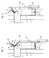
- eine Darstellung des Zulaufbereichs mit dem selbsttätigen Abschluß in Betriebsstellung im Vertikalschnitt in größerem Maßstab,
- Fig. 4
- eine Draufsicht auf die Darstellung der Fig. 3, die
- Fig. 5 und 6
- der Fig. 3 entsprechende Darstellungen in Verschluß- bzw. Befüllstellung,
- Fig. 7
- eine andere Ausführungsform des selbsttätigen Abschlusses in Betriebsstellung in Seitenansicht,
- Fig. 8
- den selbsttätigen Abschluß nach Fig. 7 in Frontansicht sowie die
- Fig. 9 und 10
- der Fig. 7 entsprechende Darstellungen in Verschluß- bzw. Befüllstellung.
- Fig. 1
- a vertical section and
- Fig. 2
- 2 shows a horizontal section through a light liquid separator according to the invention,
- Fig. 3
- a representation of the inlet area with the automatic closure in the operating position in a vertical section on a larger scale,
- Fig. 4
- a plan view of the illustration of FIG. 3, the
- 5 and 6
- 3 corresponding representations in the closed or filling position,
- Fig. 7
- another embodiment of the automatic closure in the operating position in side view,
- Fig. 8
- 7 in front view and the
- 9 and 10
- 7 corresponding representations in the closed or filling position.
In den Fig. 1 und 2 ist ein Leichtflüssigkeitsabscheider üblicher Bauart im Vertikalschnitt und in Draufsicht dargestellt. Der Leichtflüssigkeitsabscheider besteht aus einem als Stahlbetonfertigbauteil ausgebildeten Behälter 1 mit einer zylindrischen Außenwand 2 und einer Sohle 3, die eine Abscheidekammer 4 bilden. Der Behälter 1 besitzt auf einer Seite einen Zulauf 5 für das Leicht-/Schwerflüssigkeitsgemisch und auf der gegenüberliegenden Seite einen Auslauf 6 für die von der Leichtflüssigkeit befreite Schwerflüssigkeit.1 and 2, a light liquid separator of a conventional type is shown in vertical section and in plan view. The light liquid separator consists of a
Das Leicht-/Schwerflüssigkeitsgemisch fließt durch ein Zulaufrohr 7, das sich innerhalb des Behälters als vertikales Tauchrohr 8 fortsetzt, in die Abscheidekammer 4 ein. Beim Durchfließen der Abscheidekammer 4 trennt sich die Leichtflüssigkeit von der Schwerflüssigkeit und steigt an die Oberfläche. Die Trennung kann durch Einbau einer - durch gestrichelte Linien angedeuteten - Koaleszenzbarriere 9 intensiviert und beschleunigt werden. Der Flüssigkeitsspiegel der Leichtflüssigkeit ist bei 10 angedeutet, derjenige der Schwerflüssigkeit bei 11. Die am Grunde der Abscheidekammer 4 gesammelte, von der Leichtflüssigkeit befreite Schwerflüssigkeit steigt an der dem Zulauf 5 gegenüberliegenden Seite hinter einer Tauchwand 12 nach oben und wird über ein Auslaufrohr 13 abgezogen.The light / heavy liquid mixture flows through an
Im dargestellten Ausführungsbeispiel ist der selbsttätige Abschluß im Zulaufbereich, und zwar als Drehklappe 14 innerhalb des Tauchrohrs 8 vorgesehen; er kann anhand der Fig. 3, die als Ausschnitt aus Fig. 1 in größerem Maßstab eine erste Ausführungsform zeigt, näher erläutert werden.In the exemplary embodiment shown, the automatic closure is provided in the inlet area, specifically as a
Fig. 3 zeigt den selbsttätigen Abschluß in Betriebsstellung, d.h. mit geöffneter Drehklappe 14. Die Drehklappe 14 ist in dem Tauchrohr 8 um eine Drehachse 15 in einem Stahlring 16 drehbar gelagert. Die Drehklappe 14 ist drehfest mit dem einen Ende eines unteren Stabes 18 eines parallelogrammartigen Gestänges 17 verbunden, das noch einen vertikalen Stab 19 und einen oberen Stab 20 aufweist. Die Stäbe 18, 19 und 20 sind jeweils bei 21 gelenkig miteinander verbunden. Der obere Stab 20 ist an seinem anderen Ende bei 22 in einem Lager 23 gelenkig gelagert, das an einer schrägen Deckplatte 24 an dem Tauchrohr 8 befestigt ist. Durch Auf- oder Abbewegung des Gestänges 17 in Richtung des Doppelpfeils 25, wobei die Stäbe 18 und 19 jeweils um einen Winkel von 90 Grad verschwenkt werden, kann die Drehklappe 14 geöffnet oder geschlossen werden. Wie die Draufsicht gemäß Fig. 4 erkennen läßt, können gleichartige Gestänge 17' und 17'' symmetrisch zu bei den Seiten des Tauchrohrs 8 angeordnet sein.3 shows the automatic closure in the operating position, ie with the
An dem vertikalen Stab 19 bzw. den Stäben 19', 19'' ist ein Steuerkörper 26 bzw. sind Steuerkörper 26', 26'' befestigt, die im dargestellten Ausführungsbeispiel jeweils aus einem zylindrischen, oben offenen Rohr bestehen. Der Steuerkörper 26 ist an dem Gestänge 17 so angeordnet, daß seine Oberkante 27 im Betriebszustand unterhalb des Flüssigkeitsspiegels 10 liegt; er füllt sich somit bei steigendem Flüssigkeitsniveau von selbst mit Flüssigkeit, und zwar mit Leicht-/Schwerflüssigkeitsgemisch.A
Wie Fig. 3 weiterhin zeigt, befindet sich am Boden 28 des Steuerkörpers 26 ein Rückschlagventil 29, das nur ein Entleeren des Steuerkörpers 26 erlaubt. Bei langsamem Steigen des Flüssigkeitsspiegels in der Abscheidekammer 4 bei Inbetriebnahme kann somit zunächst noch keine Flüssigkeit in den Steuerkörper 26 eindringen; in dieser Phase wirkt der Steuerkörper 26 wie ein Schwimmer und hebt das Gestänge 17 an. Das Gestänge 17 kann durch den Steuerkörper 26 nur bis in die dargestellte Lage gehoben werden, in der die Drehklappe 14 geöffnet ist. In diesem Zustand befindet sich die Oberkante 27 des Steuerkörpers 26 unterhalb des Flüssigkeitsspiegels 10, so daß er sich mit Flüssigkeit füllt.As FIG. 3 further shows, there is a
Um das Gestänge 17 im Betriebszustand (Fig. 3) in der dargestellten oberen Lage zu halten, bei der die Drehklappe 14 geöffnet ist, befindet sich oberhalb des Tauchrohres 8 an der Deckplatte 24 ein Auslösemechanismus 30. Bei dem in Fig. 3 dargestellten Ausführungsbeispiel umfaßt dieser Auslösemechanismus 30 einen Dauermagneten 31, der an einer Gewindespindel 32 parallel zu dem oberen Stab 20 längsbeweglich angeordnet ist; die Gewindespindel 32 ist an einem Lagerblech 33 gehalten, das ebenfalls an der Deckplatte 24 befestigt ist. An dem Lagerblech 33 ist weiterhin ein Verriegelungshebel 34 angelenkt, der am vorderen Ende einen Haken 35 und am rückwärtigen Ende ein Gegengewicht 36 trägt.In order to keep the
Sowohl der Auslösemechanismus 30, also der Dauermagnet 31, als auch der Verriegelungshebel 34 mit dem Haken 35 wirken gegen einen Hebel 37, der parallel zu dem oberen Stab 20 des Gestänges 17 oberhalb des Tauchrohres 8 angeordnet und drehfest mit der Welle 38 verbunden ist, die das Gelenk 22 für das Gestänge 17 bildet und die am Ende den oberen Stab 20 bzw. an den Enden die oberen Stäbe 20', 20'' trägt.Both the
Beim Befüllen des Behälters 1 (Fig. 6) zur Inbetriebnahme bzw. Wiederinbetriebnahme muß die Drehklappe 14 in geöffneter Stellung gehalten werden, um den Zulauf zu ermöglichen. Wenn die magnetische Kraft des Dauermagneten 31 hierzu nicht ausreicht, kann zusätzlich eine mechanische Verriegelung mittels des Verriegelungshebels 34 erfolgen.When filling the container 1 (Fig. 6) for commissioning or recommissioning, the
Bei geöffneter Drehklappe 14 strömt über das Zulaufrohr 7 Leicht-/Schwerflüssigkeitsgemisch in die Abscheidekammer 4, so daß der Flüssigkeitsspiegel 10 langsam steigt. Dabei genügt allein die Auftriebskraft des mit Luft gefüllten Steuerkörpers, um das System in Betrieb zu nehmen. Sobald der Flüssigkeitsspiegel 10 den oberen Rand 27 des Steuerkörpers 26 erreicht, wird dieser mit Flüssigkeitsgemisch gefüllt. Auf das Gestänge 17, soweit es sich unterhalb des Flüssigkeitsspiegels 10 befindet, und auf den Steuerkörper 26 wirkt nun die Auftriebskraft der Flüssigkeit, die aber nicht ausreicht, um das Gestänge 17 in der oberen Lage zu halten. Deshalb wird die magnetische Kraft des Dauermagneten 31, die über eine Längsverstellung desselben zur Änderung des Hebelarms der angreifenden Kraft genau definiert werden kann, so eingestellt, daß das Differenzgewicht des Gestänges 17 zum Auftrieb in der Schwerflüssigkeit sowie ein bestimmtes Auslösegewicht gerade noch gehalten werden. Ist der Behälter 1 gefüllt, dann muß der Hebel 34 selbstverständlich aus der Verriegelungsstellung gelöst werden. Dies gelingt durch das Gegengewicht 36, das den Hebel 34 in seine Ruhestellung führt, wodurch das System entriegelt wird (Fig. 3).When the
Die sich bei laufendem Betrieb in der Abscheidekammer 4 oberhalb der Schwerflüssigkeit ansammelnde Leichtflüssigkeit verdrängt im oberen Bereich die Schwerflüssigkeit. Erreicht die Leichtflüssigkeitsschicht mit ihrer Unterkante die Oberkante 27 des Steuerkörpers 26, so kann sie dennoch nicht in deren Hohlraum eindringen, weil dieser mit Schwerflüssigkeit gefüllt ist. Bei weiterer Abscheidung von Leichtflüssigkeit und dementsprechendem Absinken des Schwerflüssigkeitsspiegels 11 verringert sich der auf den Steuerkörper 26 wirkende Auftrieb; es beginnt eine Zusatzkraft auf den Dauermagneten 31 zu wirken, die schließlich zu einem Lösen der durch ihn bewirkten Festhaltung führt. Durch die potentielle Energie des herunterfallenden Gestänges 17 wird nun die Drehklappe 14 geschlossen (Fig. 5). Der Hebel 37 erfährt bei der Abwärtsbewegung des Gestänges 17 einen Anschlag gegen einen Puffer 39.The light liquid accumulating in the
Nach Absaugen der Leichtflüssigkeit aus der Abscheidekammer 4 und Entfernen des Gemischs aus dem Steuerkörper 26, das durch das Rückschlagventil 29 sehr leicht ausströmen kann, wird das Gestänge 17 manuell gehoben und wieder mittels des Hebels 34 verriegelt. Hierdurch öffnet sich wieder die Drehklappe 14, so daß Flüssigkeitsgemisch zuströmen kann. Sobald dieses den Steuerkörper 26 erreicht, beginnt dieser erneut aufzuschwimmen, bis der Dauermagnet 31 wieder greift und sich der Steuerkörper 26 nicht mehr bewegen kann. Nachdem der Steuerkörper 26 durch das ansteigende Flüssigkeitsgemisch wieder mit Schwerflüssigkeit gefüllt ist, ist das System auslösebereit.After the light liquid has been sucked out of the
In den Fig. 7 bis 10 ist ein anderes Ausführungsbeispiel des erfindungsgemäßen selbsttätigen Abschlusses dargestellt, das sich von demjenigen nach den Fig. 3 bis 6 im wesentlichen durch die Gestaltung des Auslösemechanismus 40 für die Drehklappe 14 unterscheidet. Demgemäß sind entsprechende Teile des selbsttätigen Abschlusses auch mit den gleichen Bezugszeichen bezeichnet; dies gilt insbesondere für die Drehklappe 14 sowie das parallelogrammartige Gestänge 17 und den Steuerkörper 26. Die unterschiedliche Ausgestaltung des Auslösemechanismus 40 wird nachstehend zunächst anhand der Fig. 7 und 8 erläutert, wobei Fig. 7 eine Seitenansicht und Fig. 8 eine Frontansicht des Zulaufbereichs mit dem selbsttätigen Abschluß zeigen.7 to 10 show another embodiment of the automatic closure according to the invention, which differs from that according to FIGS. 3 to 6 essentially by the design of the
Bei dem Auslösemechanismus 40 ist der die Offenhaltung der Drehklappe 14 bewirkende Hebel 37 (Fig. 3) als Rollenklinke 41 ausgebildet, die mit einer Rolle 42 ausgestattet und parallel zu dem oberen Stab 20 des Gestänges 17 drehfest mit der Welle 43 und über diese bewegungsschlüssig mit dem Gestänge 17 verbunden ist. Die Rollenklinke 41 wirkt mit einem Abrollbügel 44 zusammen, der aus einem winkelförmigen Teil 45 und einem gekrümmten Teil 46 besteht; der Abrollbügel 44 ist um eine horizontale Achse 47 schwenkbar gelagert. Der Abrollbügel 41 ist mittels einer mit dem winkelförmigen Teil 47 zusammenwirkenden Zugfeder 48 gegen die Rolle 42 der Rollenklinke anpreßbar. Auf diese Weise kann die Auslösekraft für das die Drehklappe 14 betätigende Gestänge 17 in Abhängigkeit von der Dicke der Leichtflüssigkeitsschicht eingestellt werden.In the
In der in Fig. 7 dargestellten Betriebsstellung wird die Rollenklinke 41 in Wirkverbundung mit dem federbelasteten Abrollbügel 44 durch die nach der jeweiligen Dichte der Leichtflüssigkeit vorgespannte Zugfeder 48 gehalten, bis die maximale Dicke der Leichtflüssigkeitsschicht erreicht ist. Durch den Auftriebsverlust des mit Schwerflüssigkeit gefüllten Steuerkörpers 26, der hier über Öffnungen 57 gefüllt werden kann, wird die Rollenklinke 41 bei einer bestimmten Dicke der Leichtflüssigkeitsschicht aus dem federbelasteten Abrollbügel 44 ausgeklinkt. Bei der Abwärtsbewegung des Gestänges 17, die durch ein Fallgewicht 49 unterstützt werden kann, rollt die Rolle 42 der Rollenklinke 41 auf dem gekrümmten Teil 46 des Abrollbügels 44 ab. Dadurch wird die Drehklappe 14 geschlossen. Die Verschlußstellung zeigt Fig. 9.In the operating position shown in FIG. 7, the
Zur Inbetriebnahme oder Wiederinbetriebnahme des Leichtflüssigkeitsabscheiders nach Absaugen oder Abpumpen der Leichtflüssigkeit wird durch manuelle Ausübung einer Zugkraft am Gestänge 17, z.B. über eine Zugvorrichtung 50, das Gestänge 17 nach oben geführt, bis die Rolle 42 wieder in ihre Grundstellung an der Rollenklinke 41 einrastet. Da in diesem Zustand noch der Auftrieb fehlt, ist eine Rückhaltung erforderlich, die über eine Halteklinke 51 bewirkt wird. Die Halteklinke 41 ist, wie der Abrollbügel 44, an einer Lagerkonsole 52 gelagert; sie wirkt mit einem Bolzen 53 an der Rollenklinke 41 zusammen.To put the light liquid separator into operation or put it back into operation after the light liquid has been sucked off or pumped out, manual pulling of the
Zur selbsttätigen Auslösung ist die Halteklinke 51 über eine Schwimmerstange 54 mit einer Schwimmerkugel 55 verbunden; die Schwimmerstange 54 ist in einer Schwimmerführung 56 geführt. Beim Ansteigen des Flüssigkeitsspiegels im Behälter 1 erhält die Schwimmerkugel 55 oberhalb der Befüllmarke des Steuerkörpers 26 einen Auftrieb, der bis zum Ruhewasserspiegel die Halteklinke 51 vom Bolzen 53 reibungsfrei entkoppelt. Dies wird dadurch erreicht, daß der Auftrieb der Schwimmerkugel 55 erst dann einsetzt, wenn der mit Schwerflüssigkeit gefüllte Steuerkörper 26 keinen Auftriebsverlust mehr erfährt und bereits durch den Auslösemechanismus 40 gehalten wird.For automatic release, the holding
Wird, ohne die Leichtflüssigkeit abgesaugt zu haben, versucht, den selbsttätigen Abschluß wieder in Betrieb zu nehmen, so ist dies nicht möglich, da der Auslösemechanismus 40 infolge des überschrittenen Auftriebsverlustes des Steuerkörpers 26 nicht mehr in die Rastung in dem Abrollbügel 44 eingeklinkt werden kann und die Halteklinke 51 noch immer durch den Auftrieb der Schwimmerkugel 55 entkoppelt ist. Eine Wiederinbetriebnahme des Leichtflüssigkeitsabscheiders ist erst nach Entsorgung der Leichtflüssigkeit möglich.Is, without having sucked off the light liquid, tries to put the automatic closure back into operation, this is not possible since the
Der besondere Vorteil dieser Ausführungsform besteht in einer extremen Leichtgängigkeit des Systems. Die Reibung von Rollenklinke 41, Abrollbügel 44, Gestänge 17 und Drehklappe 14 werden durch die Konstruktion weitestgehend minimiert; dadurch wird die Empfindlichkeit des Systems erheblich gesteigert.The particular advantage of this embodiment is that the system is extremely easy to move. The friction of
Claims (17)
- Light liquid separator with an intake (5) for a light/heavy liquid mixture, a separator chamber (4) for separating the mixture and an outlet (6) for the heavy liquid, wherein the intake and/or outlet comprise(s) an immersion pipe (8, 12), and with an automatic closure (14) which can be controlled by the difference in the relative densities of the heavy liquid and the light liquid and is formed as a pivoted flap, characterised in that the pivoted flap (14) is disposed in the intake or the outlet inside the immersion pipe (8) and can pivot about an axis (15) which intersects the longitudinal axis of the latter at a right angle, that the pivoted flap (14) is connected in a non-rotatable manner to one end of a lower rod (18) of a parallelogram-like linkage (17) which, in addition to a vertical rod (19) flexibly connected to the other end of the rod (18), comprises an upper rod (20), one end of which is flexibly connected to the vertical rod (19) and the other end of which is articulated above the light liquid level (10) to the immersion pipe (8) in the extension of the longitudinal axis of the latter, and that a release mechanism (30, 40) is provided which co-operates with the linkage (17), holds the latter in the raised position and the pivoted flap (14) in the open position and can be released by a control force which is dependent upon the difference in the relative densities of the heavy liquid and the light liquid, so that the linkage (17) moves downwards and the pivoted flap (14) is closed.
- Light liquid separator according to claim 1, characterised in that at least one hollow control body (26), which can be filled with heavy liquid, is disposed at the linkage (17) to augment the control force.
- Light liquid separator according to claim 2, characterised in that the control body (26) is fastened to the vertical rod (19).
- Light liquid separator according to claim 2 or 3, characterised in that the control body (26) consists of a cylindrical pipe whose longitudinal axis extends parallel to the vertical rod (19), which pipe is closed at least at the lower end and comprises in its upper region an inlet opening (27, 57) for the heavy liquid.
- Light liquid separator according to one of claims 2 to 4, characterised in that the control body (26) is provided at its lower end with a nonreturn valve (29) which allows the hollow space to be emptied.
- Light liquid separator according to one of claims 1 to 5, characterised in that the release mechanism (30, 40) is disposed above the light liquid level (10).
- Light liquid separator according to one of claims 1 to 6, characterised in that the release mechanism (30, 40) co-operates with a lever (37, 41) which is connected to the linkage (17) so as to move with it.
- Light liquid separator according to claim 7, characterised in that the lever (37, 41) is disposed parallel to the upper rod (20) of the linkage (17).
- Light liquid separator according to one of claims 1 to 8, characterised in that a permanent magnet (31) is provided as the release mechanism (30).
- Light liquid separator according to claim 9, characterised in that the permanent magnet (31) can be displaced parallel to the direction in which the lever (37) extends.
- Light liquid separator according to claim 10, characterised in that the permanent magnet (31) is mounted on a rotatable threaded spindle (32).
- Light liquid separator according to one of claims 1 to 8, characterised in that a roll-over bow (44) is provided as the release mechanism (40), which bow co-operates with the lever formed as a roller pawl (41), the roller pawl (41) comprising a roller (42) which can roll over the circumference of the curved part (46) of the roll-over bow (44).
- Light liquid separator according to claim 12, characterised in that the roll-over bow (44) can be pressed against the roller (42) by means of a spring element.
- Light liquid separator according to claim 13, characterised in that a tension spring (48) is provided as the spring element.
- Light liquid separator according to one of claims 12 to 14, characterised in that a falling weight (49) is disposed at the linkage to augment the closing force.
- Light liquid separator according to one of claims 1 to 15, characterised in that a locking mechanism (34, 35 or 51, 53), which co-operates with the lever (37, 41), is provided for the linkage (17).
- Light liquid separator according to claim 16, characterised in that the locking mechanism comprises a holding pawl (51), which co-operates with the lever (41).
Applications Claiming Priority (2)
| Application Number | Priority Date | Filing Date | Title |
|---|---|---|---|
| DE4311719A DE4311719A1 (en) | 1993-04-08 | 1993-04-08 | Light liquid separator with an automatic closure |
| DE4311719 | 1993-04-08 |
Publications (2)
| Publication Number | Publication Date |
|---|---|
| EP0619131A1 EP0619131A1 (en) | 1994-10-12 |
| EP0619131B1 true EP0619131B1 (en) | 1997-06-04 |
Family
ID=6485148
Family Applications (1)
| Application Number | Title | Priority Date | Filing Date |
|---|---|---|---|
| EP94105282A Expired - Lifetime EP0619131B1 (en) | 1993-04-08 | 1994-04-05 | Light liquid separator with automatic shut-off |
Country Status (6)
| Country | Link |
|---|---|
| EP (1) | EP0619131B1 (en) |
| AT (1) | ATE153870T1 (en) |
| CZ (1) | CZ284468B6 (en) |
| DE (2) | DE4311719A1 (en) |
| DK (1) | DK0619131T3 (en) |
| HU (1) | HUT71006A (en) |
Families Citing this family (2)
| Publication number | Priority date | Publication date | Assignee | Title |
|---|---|---|---|---|
| DE102010005778A1 (en) * | 2009-05-25 | 2011-01-05 | Opanski, Josef Zoltan, Dipl.-Ing. (FH) | Device for automatically closing an inlet of a container for receiving a liquid and separating device |
| AT509469B1 (en) * | 2010-02-22 | 2011-09-15 | Tiba Austria Gmbh | FLOAT-CONTROLLED VALVE |
Family Cites Families (15)
| Publication number | Priority date | Publication date | Assignee | Title |
|---|---|---|---|---|
| DE7439213U (en) * | 1975-03-27 | Buderus'sche Eisenwerke | Lid lock for float guide cage | |
| DE491770C (en) * | 1930-02-15 | Paul Eysoldt | Automatic flow lock for a light liquid separator | |
| AT114872B (en) * | 1927-06-25 | 1929-11-11 | Dabeg Maschinenfabriks Ag | Separator for light liquids from waste water. |
| DE662908C (en) * | 1937-04-08 | 1938-07-25 | Paul Breidenbach Dr Ing | Flow barrier for light liquid separator |
| GB1535282A (en) * | 1977-05-17 | 1978-12-13 | Cjb Dev Ltd | Gravity separation apparatus |
| DE2838559A1 (en) * | 1978-09-04 | 1980-03-20 | Buderus Ag | Light liquid separator with automatic inlet valve - operated by float directly above valve with vertical shaft |
| DE2928701A1 (en) * | 1979-07-16 | 1981-02-12 | Ludwig Hunkel | Light mineral oil products separator - with inflow stop valve actuated by interface sensor |
| CH671988A5 (en) * | 1986-03-05 | 1989-10-13 | Paul Wenger | |
| DE8628211U1 (en) * | 1986-10-23 | 1986-11-27 | Buderus Ag, 6330 Wetzlar, De | |
| DE3702482A1 (en) * | 1987-01-28 | 1988-08-11 | Nikolaus Hammerschmitt | LIGHT LIQUID SEPARATOR WITH AUTOMATIC CLOSURE |
| DE3838070A1 (en) * | 1988-11-10 | 1990-05-17 | Nikolaus Hammerschmitt | LIGHT LIQUID SEPARATOR |
| DE8915490U1 (en) * | 1989-03-15 | 1990-08-02 | Benkeser, Michael, Dipl.-Ing. (Fh), 7709 Hilzingen, De | |
| AT393670B (en) * | 1989-11-17 | 1991-11-25 | Nageler Betonwerk | Mineral oil separator |
| AT396715B (en) * | 1991-04-30 | 1993-11-25 | Ortner Bauwaren | SHUT-OFF DEVICE |
| DE9105725U1 (en) * | 1991-05-08 | 1991-08-29 | Basika Entwaesserungen Gmbh, 5600 Wuppertal, De |
-
1993
- 1993-04-08 DE DE4311719A patent/DE4311719A1/en not_active Withdrawn
-
1994
- 1994-04-05 AT AT94105282T patent/ATE153870T1/en not_active IP Right Cessation
- 1994-04-05 DE DE59402967T patent/DE59402967D1/en not_active Expired - Fee Related
- 1994-04-05 EP EP94105282A patent/EP0619131B1/en not_active Expired - Lifetime
- 1994-04-05 DK DK94105282.1T patent/DK0619131T3/en active
- 1994-04-06 CZ CZ94808A patent/CZ284468B6/en not_active IP Right Cessation
- 1994-04-07 HU HU9400994A patent/HUT71006A/en unknown
Also Published As
| Publication number | Publication date |
|---|---|
| ATE153870T1 (en) | 1997-06-15 |
| HU9400994D0 (en) | 1994-06-28 |
| DE59402967D1 (en) | 1997-07-10 |
| DE4311719A1 (en) | 1994-10-13 |
| CZ80894A3 (en) | 1995-08-16 |
| CZ284468B6 (en) | 1998-12-16 |
| DK0619131T3 (en) | 1997-12-22 |
| EP0619131A1 (en) | 1994-10-12 |
| HUT71006A (en) | 1995-11-28 |
Similar Documents
| Publication | Publication Date | Title |
|---|---|---|
| DE3915076C2 (en) | ||
| DE3305409A1 (en) | Storm separation works | |
| EP0368084B1 (en) | Separator for non-miscible liquids | |
| EP0619131B1 (en) | Light liquid separator with automatic shut-off | |
| DE2323687C2 (en) | Backflow and odor trap for liquids | |
| EP0458224A1 (en) | Segmental throttle with float | |
| EP0509422B1 (en) | Apparatus for controlling the overflow and water level of hydraulic installations | |
| DE3510171A1 (en) | Liquid-retention device for installation into a liquid-storage chamber | |
| DE3817444A1 (en) | Float-controlled regulating device for changing the flow cross-section of the outlet opening of a liquid container, especially a rain retention basin | |
| EP1580338B1 (en) | Flush valve for a flushing cistern | |
| DE102009025388A1 (en) | Device for protecting container of separating device i.e. volatile liquid separator, against penetration of liquid over outlet of container, has valve opening located along flow direction of liquid over outlet behind outlet opening | |
| EP2256575B1 (en) | Device for self-actuated closing of an inflow of a container for holding a liquid and separation device | |
| EP1219753B1 (en) | Device for the surge flushing for cleaning sewers | |
| EP1039052B1 (en) | Method for cleaning a collecting tank for fluids, a collecting tank and a flushing drum | |
| DE3718812A1 (en) | METHOD FOR OPERATING THE CLOSING MECHANISM OF A FLOAT-CONTROLLED BUTTERFLY VALVE OF A SINK CHAMBER FOR RINSING A LIQUID STORAGE SPACE, AND DEVICE FOR CARRYING OUT THE METHOD | |
| DE2337853C2 (en) | Backflow and odor trap for liquids, especially waste water | |
| EP3228373B1 (en) | Device for recovering light liquid run-off from a technical piece of equipment or a device | |
| EP0565483B1 (en) | Basin in a waste water plant | |
| DE4137768C1 (en) | Automatic hoist with downwards open bell - has outlet tube, whose top end retains movably top-open float pot | |
| EP0658657A2 (en) | Flushing device | |
| WO2001090486A2 (en) | Device for recovering oil from an oil-slick on a stretch of water | |
| EP3219864B1 (en) | Liquid recipient with valve and corresponding method of use producing a rinsing surge | |
| DE19735592C2 (en) | Device for actuating a mechanism of a flushing device | |
| DE311457C (en) | ||
| EP2204226B1 (en) | Device for securing a container/separator against backflow of liquids |
Legal Events
| Date | Code | Title | Description |
|---|---|---|---|
| PUAI | Public reference made under article 153(3) epc to a published international application that has entered the european phase |
Free format text: ORIGINAL CODE: 0009012 |
|
| AK | Designated contracting states |
Kind code of ref document: A1 Designated state(s): AT BE CH DE DK ES FR GB GR IE IT LI LU NL PT SE |
|
| 17P | Request for examination filed |
Effective date: 19940928 |
|
| 17Q | First examination report despatched |
Effective date: 19951116 |
|
| GRAG | Despatch of communication of intention to grant |
Free format text: ORIGINAL CODE: EPIDOS AGRA |
|
| GRAH | Despatch of communication of intention to grant a patent |
Free format text: ORIGINAL CODE: EPIDOS IGRA |
|
| GRAH | Despatch of communication of intention to grant a patent |
Free format text: ORIGINAL CODE: EPIDOS IGRA |
|
| GRAA | (expected) grant |
Free format text: ORIGINAL CODE: 0009210 |
|
| AK | Designated contracting states |
Kind code of ref document: B1 Designated state(s): AT BE CH DE DK ES FR GB GR IE IT LI LU NL PT SE |
|
| PG25 | Lapsed in a contracting state [announced via postgrant information from national office to epo] |
Ref country code: IT Free format text: LAPSE BECAUSE OF FAILURE TO SUBMIT A TRANSLATION OF THE DESCRIPTION OR TO PAY THE FEE WITHIN THE PRE;WARNING: LAPSES OF ITALIAN PATENTS WITH EFFECTIVE DATE BEFORE 2007 MAY HAVE OCCURRED AT ANY TIME BEFORE 2007. THE CORRECT EFFECTIVE DATE MAY BE DIFFERENT FROM THE ONE RECORDED.SCRIBED TIME-LIMIT Effective date: 19970604 Ref country code: GR Free format text: LAPSE BECAUSE OF FAILURE TO SUBMIT A TRANSLATION OF THE DESCRIPTION OR TO PAY THE FEE WITHIN THE PRESCRIBED TIME-LIMIT Effective date: 19970604 Ref country code: ES Free format text: THE PATENT HAS BEEN ANNULLED BY A DECISION OF A NATIONAL AUTHORITY Effective date: 19970604 |
|
| REF | Corresponds to: |
Ref document number: 153870 Country of ref document: AT Date of ref document: 19970615 Kind code of ref document: T |
|
| REG | Reference to a national code |
Ref country code: CH Ref legal event code: EP |
|
| REF | Corresponds to: |
Ref document number: 59402967 Country of ref document: DE Date of ref document: 19970710 |
|
| REG | Reference to a national code |
Ref country code: CH Ref legal event code: NV Representative=s name: PATENTANWAELTE SCHAAD, BALASS, MENZL & PARTNER AG |
|
| GBT | Gb: translation of ep patent filed (gb section 77(6)(a)/1977) |
Effective date: 19970812 |
|
| PG25 | Lapsed in a contracting state [announced via postgrant information from national office to epo] |
Ref country code: SE Effective date: 19970904 Ref country code: PT Effective date: 19970904 |
|
| ET | Fr: translation filed | ||
| REG | Reference to a national code |
Ref country code: DK Ref legal event code: T3 |
|
| PGFP | Annual fee paid to national office [announced via postgrant information from national office to epo] |
Ref country code: GB Payment date: 19980316 Year of fee payment: 5 |
|
| PG25 | Lapsed in a contracting state [announced via postgrant information from national office to epo] |
Ref country code: IE Free format text: LAPSE BECAUSE OF NON-PAYMENT OF DUE FEES Effective date: 19980330 |
|
| REG | Reference to a national code |
Ref country code: IE Ref legal event code: FD4D Ref document number: 74472 Country of ref document: IE |
|
| PLBE | No opposition filed within time limit |
Free format text: ORIGINAL CODE: 0009261 |
|
| STAA | Information on the status of an ep patent application or granted ep patent |
Free format text: STATUS: NO OPPOSITION FILED WITHIN TIME LIMIT |
|
| 26N | No opposition filed | ||
| PG25 | Lapsed in a contracting state [announced via postgrant information from national office to epo] |
Ref country code: GB Free format text: LAPSE BECAUSE OF NON-PAYMENT OF DUE FEES Effective date: 19990405 |
|
| PGFP | Annual fee paid to national office [announced via postgrant information from national office to epo] |
Ref country code: FR Payment date: 19990420 Year of fee payment: 6 |
|
| GBPC | Gb: european patent ceased through non-payment of renewal fee |
Effective date: 19990405 |
|
| PG25 | Lapsed in a contracting state [announced via postgrant information from national office to epo] |
Ref country code: FR Free format text: LAPSE BECAUSE OF NON-PAYMENT OF DUE FEES Effective date: 20001229 |
|
| REG | Reference to a national code |
Ref country code: FR Ref legal event code: ST |
|
| PGFP | Annual fee paid to national office [announced via postgrant information from national office to epo] |
Ref country code: AT Payment date: 20020412 Year of fee payment: 9 |
|
| PGFP | Annual fee paid to national office [announced via postgrant information from national office to epo] |
Ref country code: NL Payment date: 20020416 Year of fee payment: 9 |
|
| PGFP | Annual fee paid to national office [announced via postgrant information from national office to epo] |
Ref country code: LU Payment date: 20020419 Year of fee payment: 9 Ref country code: BE Payment date: 20020419 Year of fee payment: 9 |
|
| PGFP | Annual fee paid to national office [announced via postgrant information from national office to epo] |
Ref country code: DK Payment date: 20020422 Year of fee payment: 9 |
|
| PGFP | Annual fee paid to national office [announced via postgrant information from national office to epo] |
Ref country code: CH Payment date: 20020506 Year of fee payment: 9 |
|
| PG25 | Lapsed in a contracting state [announced via postgrant information from national office to epo] |
Ref country code: LU Free format text: LAPSE BECAUSE OF NON-PAYMENT OF DUE FEES Effective date: 20030405 Ref country code: AT Free format text: LAPSE BECAUSE OF NON-PAYMENT OF DUE FEES Effective date: 20030405 |
|
| PG25 | Lapsed in a contracting state [announced via postgrant information from national office to epo] |
Ref country code: LI Free format text: LAPSE BECAUSE OF NON-PAYMENT OF DUE FEES Effective date: 20030430 Ref country code: DK Free format text: LAPSE BECAUSE OF NON-PAYMENT OF DUE FEES Effective date: 20030430 Ref country code: CH Free format text: LAPSE BECAUSE OF NON-PAYMENT OF DUE FEES Effective date: 20030430 Ref country code: BE Free format text: LAPSE BECAUSE OF NON-PAYMENT OF DUE FEES Effective date: 20030430 |
|
| BERE | Be: lapsed |
Owner name: *DYCKERHOFF & WIDMANN A.G. Effective date: 20030430 |
|
| PG25 | Lapsed in a contracting state [announced via postgrant information from national office to epo] |
Ref country code: NL Free format text: LAPSE BECAUSE OF NON-PAYMENT OF DUE FEES Effective date: 20031101 |
|
| NLV4 | Nl: lapsed or anulled due to non-payment of the annual fee |
Effective date: 20031101 |
|
| REG | Reference to a national code |
Ref country code: DK Ref legal event code: EBP |
|
| REG | Reference to a national code |
Ref country code: CH Ref legal event code: PL |
|
| PGFP | Annual fee paid to national office [announced via postgrant information from national office to epo] |
Ref country code: DE Payment date: 20060613 Year of fee payment: 13 |
|
| PG25 | Lapsed in a contracting state [announced via postgrant information from national office to epo] |
Ref country code: DE Free format text: LAPSE BECAUSE OF NON-PAYMENT OF DUE FEES Effective date: 20071101 |