EP2865817A1 - Outlet fitting for a toilet cistern - Google Patents
Outlet fitting for a toilet cistern Download PDFInfo
- Publication number
- EP2865817A1 EP2865817A1 EP20130190455 EP13190455A EP2865817A1 EP 2865817 A1 EP2865817 A1 EP 2865817A1 EP 20130190455 EP20130190455 EP 20130190455 EP 13190455 A EP13190455 A EP 13190455A EP 2865817 A1 EP2865817 A1 EP 2865817A1
- Authority
- EP
- European Patent Office
- Prior art keywords
- control unit
- full
- valve body
- quantity control
- subset
- Prior art date
- Legal status (The legal status is an assumption and is not a legal conclusion. Google has not performed a legal analysis and makes no representation as to the accuracy of the status listed.)
- Granted
Links
- XLYOFNOQVPJJNP-UHFFFAOYSA-N water Substances O XLYOFNOQVPJJNP-UHFFFAOYSA-N 0.000 claims abstract description 54
- 230000036961 partial effect Effects 0.000 claims abstract description 48
- 238000005192 partition Methods 0.000 claims abstract description 34
- 230000033001 locomotion Effects 0.000 claims abstract description 19
- 238000007789 sealing Methods 0.000 claims abstract description 12
- 238000010926 purge Methods 0.000 claims abstract description 11
- 238000011010 flushing procedure Methods 0.000 claims description 21
- 239000002699 waste material Substances 0.000 claims description 9
- 238000009434 installation Methods 0.000 claims description 5
- 238000004891 communication Methods 0.000 description 3
- 238000000034 method Methods 0.000 description 3
- 230000002829 reductive effect Effects 0.000 description 3
- 230000002000 scavenging effect Effects 0.000 description 3
- 230000003213 activating effect Effects 0.000 description 1
- 230000005540 biological transmission Effects 0.000 description 1
- 230000001419 dependent effect Effects 0.000 description 1
- 230000000670 limiting effect Effects 0.000 description 1
- 230000014759 maintenance of location Effects 0.000 description 1
- 230000000284 resting effect Effects 0.000 description 1
- 230000002441 reversible effect Effects 0.000 description 1
- 239000008237 rinsing water Substances 0.000 description 1
- 230000000630 rising effect Effects 0.000 description 1
Images


Classifications
-
- E—FIXED CONSTRUCTIONS
- E03—WATER SUPPLY; SEWERAGE
- E03D—WATER-CLOSETS OR URINALS WITH FLUSHING DEVICES; FLUSHING VALVES THEREFOR
- E03D3/00—Flushing devices operated by pressure of the water supply system flushing valves not connected to the water-supply main, also if air is blown in the water seal for a quick flushing
- E03D3/12—Flushing devices discharging variable quantities of water
-
- E—FIXED CONSTRUCTIONS
- E03—WATER SUPPLY; SEWERAGE
- E03D—WATER-CLOSETS OR URINALS WITH FLUSHING DEVICES; FLUSHING VALVES THEREFOR
- E03D1/00—Water flushing devices with cisterns ; Setting up a range of flushing devices or water-closets; Combinations of several flushing devices
- E03D1/02—High-level flushing systems
- E03D1/14—Cisterns discharging variable quantities of water also cisterns with bell siphons in combination with flushing valves
- E03D1/142—Cisterns discharging variable quantities of water also cisterns with bell siphons in combination with flushing valves in cisterns with flushing valves
- E03D1/144—Cisterns discharging variable quantities of water also cisterns with bell siphons in combination with flushing valves in cisterns with flushing valves having a single flush outlet and an additional float for delaying the valve closure
-
- E—FIXED CONSTRUCTIONS
- E03—WATER SUPPLY; SEWERAGE
- E03D—WATER-CLOSETS OR URINALS WITH FLUSHING DEVICES; FLUSHING VALVES THEREFOR
- E03D1/00—Water flushing devices with cisterns ; Setting up a range of flushing devices or water-closets; Combinations of several flushing devices
- E03D1/30—Valves for high or low level cisterns; Their arrangement ; Flushing mechanisms in the cistern, optionally with provisions for a pre-or a post- flushing and for cutting off the flushing mechanism in case of leakage
- E03D1/34—Flushing valves for outlets; Arrangement of outlet valves
- E03D1/35—Flushing valves having buoyancy
-
- E—FIXED CONSTRUCTIONS
- E03—WATER SUPPLY; SEWERAGE
- E03D—WATER-CLOSETS OR URINALS WITH FLUSHING DEVICES; FLUSHING VALVES THEREFOR
- E03D1/00—Water flushing devices with cisterns ; Setting up a range of flushing devices or water-closets; Combinations of several flushing devices
- E03D1/30—Valves for high or low level cisterns; Their arrangement ; Flushing mechanisms in the cistern, optionally with provisions for a pre-or a post- flushing and for cutting off the flushing mechanism in case of leakage
- E03D1/34—Flushing valves for outlets; Arrangement of outlet valves
-
- E—FIXED CONSTRUCTIONS
- E03—WATER SUPPLY; SEWERAGE
- E03D—WATER-CLOSETS OR URINALS WITH FLUSHING DEVICES; FLUSHING VALVES THEREFOR
- E03D1/00—Water flushing devices with cisterns ; Setting up a range of flushing devices or water-closets; Combinations of several flushing devices
- E03D1/02—High-level flushing systems
- E03D1/14—Cisterns discharging variable quantities of water also cisterns with bell siphons in combination with flushing valves
- E03D2001/147—Cisterns discharging variable quantities of water also cisterns with bell siphons in combination with flushing valves having provisions for active interruption of flushing
Definitions
- the present invention relates to a drain fitting or a drain valve for a cistern according to the preamble of claim 1.
- a weight body is arranged, which can optionally be switched on the valve body.
- the flushing device of the EP 0 722 020 is designed with respect to reliability and longevity extraordinarily good and very satisfactory, the control unit or the flush volume is very limited adjustable.
- the invention has for its object to provide a waste set, which overcomes the disadvantages of the prior art.
- a waste set should be specified, with which a more flexible adjustment of the full flush and the partial flush can be achieved.
- a larger adjustment range for the two flushing quantities should be achieved.
- an expiration set comprises a valve body with a valve seat cooperating with a sealing member and a float, wherein the valve body with the sealing element from the valve seat along a movement axis of a rest position in the scavenge and movable from the scavenge to the rest position , a full-quantity control unit for controlling a full-flush, wherein the full-amount control provides a closing force to the valve body when a full-level water level is reached, and a partial quantity control unit for controlling a partial-quantity purge, wherein the partial quantity controller achieves a closing force upon reaching a partial water level on the valve body provides.
- the drain fitting comprises a partition with a float chamber below it, wherein the valve body extends through an opening through the partition wall, wherein the float is movable within the float chamber along the actuating axis and cooperates with this hydraulically.
- the partition wall has a full-quantity control opening and a partial quantity control opening through which air and / or water can pass from below the upper side of the partition so that the pressure ratios between the float chamber and the areas outside the float chamber can be compensated. The hydraulic balance within the float chamber is thus disturbed.
- the state of the full-quantity control opening and the partial-quantity control opening is controllable by the full-quantity control unit and the subset control unit.
- the arrangement of the control openings in the partition wall, the area above the partition remains substantially free. This area can then be used for the design of the subset control unit and the full amount control unit. Consequently, the arrangement of the control openings in the partition a greater freedom of design for the design of the control units are created.
- the closing force is a mechanical closing force acting on the float in the direction of the axis of movement.
- the closing force is provided by mechanical contact between parts of the full-quantity control unit and the partial quantity control unit.
- the control openings are controlled in accordance with the intended flushing. Consequently, therefore, act on the valve body in the process of closing a mechanical force component, which is acted upon by the closing force on the valve body, and a hydraulic component, which is provided by the control of the control opening. Due to the hydraulic influence via the active control of the control openings, the mechanical closing force can be reduced.
- the float chamber is bounded at the top by the partition wall and downwardly extends a side wall, which adjoins the partition wall.
- the side wall has an edge region, which is spaced from the valve seat, so that between the edge and the valve seat, the rinse water can flow to the drain of the cistern.
- the closing force of the respective control unit is applied directly to the valve body or via a switching element of the respective control unit on the valve body.
- each of the control unit comprises a closure member which cooperates with the respective control opening, wherein the closure member is movable relative to the corresponding control opening.
- the closure member which is part of the full-quantity control unit or the partial quantity control unit, therefore, the full-quantity control opening and the partial quantity control opening can be activated actively become.
- the full-quantity control unit has an operating rod which projects through the full-quantity control opening and acts directly on the float.
- said closing force can be applied to the valve body on the float.
- the actuating rod is movable relative to the fixed partition wall.
- the actuating rod protrudes into the float chamber so far that during the movement of the float from the rest position into the flushing position, the actuating rod and further parts of the full-quantity control unit are raised.
- the closure member is arranged.
- the closure member cooperates with the control port.
- the closure member is located within the float chamber such that the full-quantity control opening is closable when the valve body is in the rest position.
- the control port remains closed until the water level has dropped to the full level, and then the control port is opened by the full amount control unit.
- the full-quantity control unit comprises an actuating element with a water chamber, wherein the actuating element is in communication with the actuating rod.
- the actuating element can be moved and locked relative to the actuating rod, so that its height is adjustable in the cistern.
- the actuating rod preferably on locking elements.
- the water chamber fills with increasing rinse water in a cistern with the rinse water.
- the rinsing water in the water chamber becomes effective as a weight force and provides said closing force on the valve body.
- the shutter member of the full-quantity control unit is moved away from the full-quantity control port and the float chamber becomes open.
- air and / or water can enter the float chamber through the full flow control orifice, thereby disturbing the hydraulic balance within the float chamber.
- the valve body is moved from the scavenge to its rest position.
- the subset control unit remains occluded.
- the subset control unit remains at the Vollmengen Introduceung substantially in its rest position and is not operated.
- the actuating rod of the full amount control unit is mounted in a flushing position on a retaining element.
- the retention element provides a stop against movement beyond the scavenge position.
- actuating rod is preferably mounted movably in a longitudinal guide.
- the longitudinal guide extends in the direction of actuation.
- the actuating element has an air chamber which lies below the said water chamber, so that the actuating element and thus also the actuating rod and the closure member undergo buoyancy and the closure member closes the full-quantity control opening when the cistern is filled.
- the subset control unit comprises a switching element which automatically engages with the valve body when the subset control unit is raised.
- the mechanical closing force can be transferred from the subset control unit to the valve body.
- the subset control unit comprises a rod, wherein at a front end portion, a closure member is arranged.
- the closure member cooperates with the partial quantity control opening.
- the closure member is raised by the subset control opening upon actuation of the subset control unit.
- the closing member of the subset control unit preferably opens the subset control opening only when the subset control unit is operated. This means that otherwise, ie when the subset control unit is not actuated, the subset control opening remains closed.
- the partial flow control opening is open, water can flow into the float chamber, in which case the hydraulic equilibrium is correspondingly influenced.
- the state of the full-quantity control opening is closed at the subset control.
- the closing member of the full-quantity control unit closes the full-quantity control opening, so that the float chamber is closed at the top.
- the closure is achieved in particular by the buoyancy of the actuating element with the air chamber.
- the closure member of the Operamengenpültician is outside the float chamber.
- the subset control unit comprises an actuating element with a water chamber, wherein the actuating element via the switching member to the valve body is switchable and wherein the actuating element with the rod, in particular adjustable, is in communication.
- the water chamber provides a weight with empty cistern, which then acts as a closing force. The closing force is transferred as mentioned via the switching element on the valve body.
- the actuating element of the full-quantity control unit lies in the installed position below the actuating element of the partial quantity control unit. Both actuators can be adjusted in height in the cistern preferably.
- the drain fitting further comprises an actuating device.
- the actuator acts on the full body flushing directly on the valve body.
- the valve body is raised accordingly.
- the full-quantity control unit acts on the valve body for the movement from the scavenge to the rest position. In the partial flush, the actuator over the subset control unit on the valve body, wherein the subset control unit is raised in the actuation and at the same time lifts the valve body, wherein the subset control unit with the valve body, in particular via the switching member, is temporarily connectable.
- the subset control unit comprises a sleeve-related sleeve which at least partially surrounds the valve body, the valve body having a stopper against which the sleeve abuts in the partial quantity purge such that the valve body can be raised.
- the valve body has a receiving opening engaged with the operating device
- the partial quantity control unit has a receiving opening which engages with the operating device.
- the elements are moved from the rest position to the rinse.
- the actuating rods of the full amount control unit and the rod of the subset control unit are movable along a longitudinal direction parallel to the movement of the valve body.
- the full-quantity control opening and the partial quantity control opening are arranged in a section of the partition wall lying in the installation position in the horizontal.
- the full-quantity control opening and the partial quantity control opening are in the installation position with respect to the horizontal on the same plane.
- the drain fitting further comprises a housing which is firmly connected to the cistern, wherein the valve body is movably mounted in the housing.
- the housing moreover preferably comprises the float chamber and the partition wall.
- closure members of the two control units can be interleaved with each other.
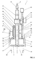
- FIG. 1 a waste set 1 for a cistern in the rest position is shown.
- the cistern is not shown here.
- the waste set 1 is connected in a known manner with the cistern and is used to control a Generalmengen facedung or a full flush. When flushing a certain amount of water to a sanitary device, such as a toilet or a urinal is supplied.
- the drain fitting 1 comprises a valve body 2 with a sealing element 4 and a float 5, a full amount control unit 6 and a partial quantity control unit 7. Further, the drain set comprises a partition 8 with a below this float chamber 9, in which the float 5 is arranged to be movable.
- valve body 2 is connected to the sealing element 4 by a valve seat 3 along a movement axis B from a rest position to a scavenge position and from the scavenge position into the Resting position movable.
- FIG. 1 is the valve body 2 in the rest position, in which case the sealing element 4 rests against the valve seat 3, so that no water can the drain 35, which adjoins the valve seat 3, can be fed.
- Valve seat 3 and drain 35 may be parts of the drain fitting 1 or the cistern.
- the full-quantity control unit 6 is for controlling a full-quantity purging.
- the full-quantity control unit 6 provides a closing force F on the valve body 2 when a water level intended for the full amount is reached, denoted by VM in the figures.
- the full-quantity control unit 6 thus causes a mechanical closing force F on the valve body 2, so that it is moved back from the scavenging position to the rest position.
- the subset control unit 7 is for controlling a subset purge.
- the subset control unit 7 upon reaching a water level intended for the subset, denoted by TM in the figures, provides a closing force F on the valve body 2. Again, a mechanical force is provided on the valve body 2, so that it is moved back from the spill position to the rest position.
- the drain fitting 1 comprises a partition wall 8 with a float chamber 9 located below this partition 8.
- the float chamber 9 is bounded at the top by the partition 8.
- a side wall 36 extends away from the partition wall 8 and limits the float chamber 9 laterally.
- the side wall 36 adjoins the partition 8 and surrounds this circumferentially.
- the side wall 36 Towards the bottom, ie against the valve seat 3, the side wall 36 has an edge region 37. This edge region 37 is spaced from the valve seat 3, so that between the valve seat 3 and the edge portion 37, a gap 38 is provided, through which the rinse water 35 can be supplied.
- the partition wall 8 has an opening 10 through which the valve body 2 extends.
- the valve body 2 is mounted movably in the opening 10 along the actuation axis B.
- the float 5 is located here within the float chamber 9 and is movable along the actuating axis B.
- the float 5 works hydraulically with the float chamber 9 together. Due to the conclusion after At the top through the partition wall 8 is formed with raised float 9, when the valve body 2 is in the scavenge, a hydraulic balance within the float chamber 9, wherein the float 5 is held in the scavenge position due to this balance. In other words, a negative pressure is provided in the float chamber 9, which keeps the float 5 and thus also the valve body 2 in the flushing position.
- the opening 10 is supplemented with a circumferential wall 39 upwards.
- the wall 39 provides an opening 40 which correspondingly guides the valve body 2 and seals against entry of air.
- the wall 39 extends completely around the opening 10, in which case the wall 39 provides the cylindrical uninterrupted opening 40.
- two control openings 11, 12 are arranged in the partition 8.
- these control openings 11, 12, which can be opened or closed the hydraulic balance within the float chamber 9 can be controlled. If one of these control openings 11, 12 is opened when the float 5 is in the flushing position, the hydraulic equilibrium in the float chamber 9 is released and the float 5 moves along the actuation axis B in the direction of the valve seat 3.
- a full-quantity control port 11 and a sub-quantity control port 12 are arranged. Through these control openings 11, 12, air and / or water from the top 13 of the partition 8 below this, so in the float chamber 9, reach. Thus, the pressure conditions between the float chamber 9 and the areas 14 outside the float chamber 9 can be compensated.
- the areas 14 are provided by the cistern.
- the state of the full-quantity control port 11 and the state of the sub-quantity control port 12 are controlled by the full-quantity control unit 6 and the subset control unit 7. In the full-flush, the full-quantity control port 11 is opened and the partial-quantity control port 12 remains in the closed state.
- the subset control unit 7 is operated the operation of the control openings 11, 12 exactly the reverse, there, the partial flow control opening 12 is opened and the full-quantity control opening 11 remains closed.
- a mechanical closing force F is provided on the valve body 2, and on the other hand, a hydraulic component acts through the opening of the control openings 11, 12. Due to the hydraulic control by the control openings 11, 12, the closing force F, which by the full amount control unit 6 and by the Subset control unit 7 is to be provided reduced. As a result, the mass of the partial quantity control unit 7 or of the full quantity control unit 6 can be reduced accordingly.
- the waste set is displayed during full flush.
- the sealing element 4 is here spaced from the valve seat 3.
- the entire valve body 2 is raised.
- the rinse water can pass through the gap 38 to the drain 35.
- the water level in the cistern drops accordingly.
- the weight force of the full-quantity control unit 6 starts to act and the full-quantity control unit 6 provides a closing force F on the valve body 2, here on the float 5.
- This closing force F pushes the valve body 2 along the movement axis B toward the valve seat 3.
- the full-quantity control opening 11 is opened by the full-quantity control unit 6 and the hydraulic balance in the float chamber 9 is disturbed.
- a hydraulic component is also provided on the valve body 2, which allows the valve body 2 to move in the direction of the valve seat 3.
- the subset control opening 12 remains closed because the subset control unit 7 not operated.
- the subset control unit 7 is pressed against the subset control opening 12 due to its weight.
- the subset control unit 7 is correspondingly operated and raises the valve body 2.
- a Heidelbergorgang 15 is provided in the embodiment shown.
- the subset control opening 12 is already opened.
- the weight force of the subset control unit 7 begins to act and provides a closing force F on the valve body 2 via the switching element 15.
- the hydraulic balance within the float chamber 9 is disturbed by the already opened subset control opening 12. It can reach water via the partial quantity control opening 12 in the float chamber 9.
- mechanical and hydraulic force components also act on the valve body 2, so that it can be closed accordingly.
- the full-quantity control port 11 remains closed.
- Each of the control units 6, 7 comprises a closure member 16, 17, which cooperates with the respective control opening 11, 12.
- the closure member 16, 17 is movable by the control unit 6, 7 relative to the corresponding control opening 11, 12.
- the closure member 16, 17 may be formed in various ways. In the present embodiment, each of the closure members 16 or 17 on a valve plate, which is larger than corresponding control opening 11, 12 and so closes them.
- the full-quantity control unit 6 has an actuating rod 18.
- the operating rod 18 protrudes through the full-quantity control opening 11 in the present embodiment and acts directly on the float 5.
- This actuating rod 18 is the closing force F applied to the float 5.
- the actuating rod 18 is here with an actuating element 27 in connection.
- the actuating element 27 has, in the present embodiment, a water chamber 28 and an air chamber 31 located below the water chamber 28.
- the water chamber 28 fills with rising water level in the cistern with rinse water.
- the air chamber 31 provides a corresponding lift, so that the closure member 16 rests against the full-quantity control opening 11 in the rest position.
- the actuator 27 is slidable and adjustable relative to the actuating rod 18.
- This height adjustment controls the level of full-volume control and thus also the volume removal from the cistern during full-volume control.
- FIG. 1 can be well recognized that the actuating rod 18 protrudes into the float chamber 9 so far that during the movement of the float from the rest position into the flushing position, the actuating rod 18 and other parts of the full amount control unit 6 is raised.
- the closure member 16 is arranged on the actuating rod 18.
- the closure member 16 is located within the float chamber 5.
- the closure member 16 is located in the float chamber 9 such that in the raised state, the full-quantity control opening 11 can be closed. The closure is ensured by the buoyancy of the actuating element 27.
- the actuating rod 18 of the full-quantity control unit 6 can be suspended in a rinsing position on a retaining element 20.
- the retaining element 20 provides a stop for the actuating rod 18 with respect to a movement in the direction of the float chamber 9 ready.
- the function of this stop is in the FIG. 1 shown accordingly.
- the actuating rod 18 is guided in the region of the stop with a longitudinal guide on the drain fitting. In the FIG. 5 an exemplary longitudinal guide 41 is shown.
- the subset control unit 12 comprises a switching element 15.
- the switching element 15, which here has the shape of a shift lever, is automatically connected to the valve body 2 when the subset control unit 12 is raised.
- the switching element 15 is present at a stop element 42 on the valve body 2.
- the closing force F is transferred from the subset control unit 12 to the valve body 2 accordingly.
- the switching member 15 pivots back automatically, so that the connection between the subset control unit 7 and valve body 2 is released.
- the partial quantity control unit 12 comprises a rod 21, the closure member 17 being arranged at a front end region 19.
- the closure member 17 is raised accordingly by the subset control opening 12 and releases it.
- the closure member 17 is arranged outside the float chamber 9. The shutter 17 is moved toward the sub-quantity control opening via the weight force of the sub-quantity control unit 7.
- the subset control unit 7 also has an actuator.
- the actuating element of the partial quantity control unit 7 bears the reference numeral 29.
- the actuating element 29 in this case comprises a water chamber and communicates with the rod 21 in connection.
- the actuator 29 can be relatively move along the rod 21 and set.
- the actuating element 29 can be connected via the switching element 15 to the valve body 2.
- the water in the water chamber 30 acts as a weight and acts via the switching element 15 on the valve body 2, so that it can be moved from the scavenging position to the rest position.
- the mechanical closing force F is provided.
- the drain fitting 1 on an actuating device acts directly on the valve body 2.
- the valve body 2 has a at its upper end Receiving opening 24, in which the actuating device can engage accordingly.
- the actuating device acts on the valve body 2 during the partial quantity flushing via the partial quantity control unit 7.
- the partial quantity control unit 7 is raised accordingly and at the same time raises the valve body 2.
- the subset control unit 7 is temporarily connected to the valve body 2 via the switching member 15, so that the closing force F can be transmitted from the subset control unit 7 to the valve body 2.
- the partial quantity control unit 7 has a sleeve 22 connected to the rod 21 for the transmission of motion to the valve body 2.
- the sleeve 22 surrounds the valve body 2 at least partially.
- the valve body 2 has a stop 23, on which the collar 22 is present in the partial flushing in such a way that the valve body 2 can be raised accordingly.
- the stop 23 thus lies above the sleeve 22.
- the partial quantity control unit 7 has a receiving opening 25.
- the receiving opening 25 is here in the region of the rod 21 with the subset control unit 7 in connection.
- the receiving opening 25 is for engagement with the actuating device. About this receiving opening the subset control unit 7 is raised accordingly.
- the partial quantity control unit 7 and also the full-quantity control unit 6 move substantially parallel to the movement of the valve body.
- the full-quantity control port 11 and the sub-quantity control port 12 are in an installation position in the horizontal portion 26 of the partition wall 8. More preferably, the full-quantity control port 11 and the sub-quantity control port 12 are substantially on the same plane. This in turn in relation to the horizontal. Alternatively, the two control openings 11, 12 in height also be offset from one another.
- the actuator 27 of the full-quantity control unit 6 is in a container 32nd movable.
- the container 32 adjoins the partition wall 8. Above the dividing wall 8, in the region of the container bottom 32, the container has an outlet opening 34.
- the container has the function of slightly slowing down the movement of the full-quantity control unit 6 by slowly pushing the water in the container 32 outward via the outlet opening 34.
- a corresponding container 43 is provided in the area of the subset control unit 7.
- This container 43 essentially ensures that the hydraulic balance within the float chamber is not canceled too soon when a partial flush is initiated.
- the container 43 is arranged in the region of the partial quantity control opening and extends away from the dividing wall 9.
- FIG. 5 a perspective view of a preferred embodiment of the drain fitting 1 is shown.
- the drain fitting 1 here further comprises a housing 44 which is firmly connected to the cistern.
- the valve body 2 and the other movable elements are in communication with the housing 44 accordingly.
- the actuators 27, 29 along the corresponding rods 18, 21 are formed adjustable in height.
Abstract
Eine Ablaufgarnitur (1) für einen Spülkasten, umfassend einen Ventilkörper (2) mit einem mit einem Ventilsitz (3) zusammenarbeitenden Dichtungselement (4) und einem Schwimmer (5), wobei der Ventilkörper (2) mit dem Dichtungselement (4) vom Ventilsitz (3) entlang einer Bewegungsachse (B) von einer Ruhelage in Spüllage und von der Spüllage in die Ruhelage bewegbar ist, eine Vollmengensteuerungseinheit (6) für die Steuerung einer Vollmengenspülung, wobei die Vollmengensteuerungseinheit (6) bei Erreichen eines für die Vollmenge vorgesehenen Wasserstandes eine Schliesskraft (F) auf den Ventilkörper (2) bereitstellt, und eine Teilmengensteuerungseinheit (7) für die Steuerung einer Teilmengenspülung, wobei die Teilmengensteuerungseinheit (7) bei Erreichen eines für die Teilmenge vorgesehenen Wasserstandes eine Schliesskraft (F) auf den Ventilkörper (2) bereitstellt, eine Trennwand (8) mit einer unterhalb dieser liegenden Schwimmerkammer (9), wobei sich der Ventilkörper (2) durch eine Öffnung (10) durch die Trennwand (8) hindurch erstreckt, wobei der Schwimmer (5) innerhalb der Schwimmerkammer (9) entlang der Betätigungsachse (B) bewegbar ist und mit dieser hydraulisch zusammenarbeitet, wobei die Trennwand (8) eine Vollmengensteuerungsöffnung (11) und eine Teilmengensteuerungsöffnung (12) aufweist, durch welche Luft und/oder Wasser von der Oberseite (13) der Trennwand (8) unterhalb diese gelangen kann, derart dass die Druckverhältnisse zwischen der Schwimmerkammer (9) und den Bereichen (14) ausserhalb der Schwimmerkammer (9) ausgleichbar ist, und wobei der Zustand der Vollmengensteuerungsöffnung (11) und der Teilmengensteuerungsöffnung (12) durch die Vollmengensteuerungseinheit (6) und die Teilmengensteuerungseinheit (7) steuerbar ist.A drain fitting (1) for a cistern, comprising a valve body (2) having a sealing element (4) cooperating with a valve seat (3) and a float (5), the valve body (2) being connected to the sealing element (4) from the valve seat (3) along a movement axis (B) of a Rest position in the rinse position and from the rinse position to the rest position, a full-quantity control unit (6) for controlling a full-volume purge, wherein the full-quantity control unit (6) provides a closing force (F) on the valve body (2) upon reaching a full-level water level, and a subset control unit (7) for controlling a subset purge, wherein the subset control unit (7) provides a closing force (F) on the valve body (2) upon reaching a water level intended for the subset, a partition wall (8) having a float chamber (9) below it, the valve body (2) extending through an opening (10) through the partition wall (8), the float (5) passing inside the float chamber (9) the actuating axis (B) is movable and cooperates with this hydraulically, wherein the partition wall (8) has a full-quantity control opening (11) and a partial flow control opening (12) through which air and / or water can pass from the upper side (13) of the dividing wall (8) underneath, such that the pressure ratios between the float chamber (12) 9) and the areas (14) outside the float chamber (9) is compensated, and wherein the state of the full-quantity control port (11) and the partial-quantity control port (12) is controllable by the full-quantity control unit (6) and the subset control unit (7).
Description
Die vorliegende Erfindung betrifft eine Ablaufgarnitur bzw. ein Ablaufventil für einen Spülkasten nach dem Oberbegriff von Anspruch 1.The present invention relates to a drain fitting or a drain valve for a cistern according to the preamble of
Aus dem Stand der Technik sind Ablaufgarnituren zur wahlweisen Auslösung einer Vollmengenspülung oder Teilmengenspülung bekannt.Expiration sets for selectively triggering a full flush or partial flush are known from the prior art.
Beispielsweise zeigt die
Obwohl die Spüleinrichtung der
Ausgehend von diesem Stand der Technik liegt der Erfindung eine Aufgabe zugrunde, eine Ablaufgarnitur anzugeben, welche die Nachteile des Standes der Technik überwindet. Insbesondere soll eine Ablaufgarnitur angegeben werden, mit welcher eine flexiblere Einstellung der Vollmengenspülung und der Teilmengenspülung erreicht werden kann. Insbesondere soll ein grösserer Einstellbereich für die beiden Spülmengen erreicht werden. Diese Aufgabe löst der Gegenstand von Anspruch 1. Demgemäss umfasst eine Ablaufgarnitur einen Ventilkörper mit einem mit einem Ventilsitz zusammenarbeitenden Dichtungselement und einem Schwimmer, wobei der Ventilkörper mit dem Dichtungselement vom Ventilsitz entlang einer Bewegungsachse von einer Ruhelage in Spüllage und von der Spüllage in die Ruhelage bewegbar ist, eine Vollmengensteuerungseinheit für die Steuerung einer Vollmengenspülung, wobei die Vollmengensteuerung bei Erreichen eines für die Vollmenge vorgesehenen Wasserstandes eine Schliesskraft auf den Ventilkörper bereitstellt, und eine Teilmengensteuerungseinheit für die Steuerung einer Teilmengenspülung, wobei die Teilmengensteuerung bei Erreichen eines für die Teilmenge vorgesehenen Wasserstandes eine Schliesskraft auf den Ventilkörper bereitstellt. Weiter umfasst die Ablaufgarnitur eine Trennwand mit einer unterhalb dieser liegenden Schwimmerkammer, wobei sich der Ventilkörper durch eine Öffnung durch die Trennwand hindurch erstreckt, wobei der Schwimmer innerhalb der Schwimmerkammer entlang der Betätigungsachse bewegbar ist und mit dieser hydraulisch zusammenarbeitet. Die Trennwand weist eine Vollmengensteuerungsöffnung und eine Teilmengensteuerungsöffnung auf, durch welche Luft und/oder Wasser von der Oberseite der Trennwand unterhalb diese gelangen kann, derart dass die Druckverhältnisse zwischen der Schwimmerkammer und den Bereichen ausserhalb der Schwimmerkammer ausgleichbar sind. Das hydraulische Gleichgewicht innerhalb der Schwimmerkammer wird also gestört. Der Zustand der Vollmengensteuerungsöffnung und der Teilmengensteuerungsöffnung ist durch die Vollmengensteuerungseinheit und die Teilmengensteuerungseinheit steuerbar.Based on this prior art, the invention has for its object to provide a waste set, which overcomes the disadvantages of the prior art. In particular, a waste set should be specified, with which a more flexible adjustment of the full flush and the partial flush can be achieved. In particular, a larger adjustment range for the two flushing quantities should be achieved. Accordingly, an expiration set comprises a valve body with a valve seat cooperating with a sealing member and a float, wherein the valve body with the sealing element from the valve seat along a movement axis of a rest position in the scavenge and movable from the scavenge to the rest position , a full-quantity control unit for controlling a full-flush, wherein the full-amount control provides a closing force to the valve body when a full-level water level is reached, and a partial quantity control unit for controlling a partial-quantity purge, wherein the partial quantity controller achieves a closing force upon reaching a partial water level on the valve body provides. Further, the drain fitting comprises a partition with a float chamber below it, wherein the valve body extends through an opening through the partition wall, wherein the float is movable within the float chamber along the actuating axis and cooperates with this hydraulically. The partition wall has a full-quantity control opening and a partial quantity control opening through which air and / or water can pass from below the upper side of the partition so that the pressure ratios between the float chamber and the areas outside the float chamber can be compensated. The hydraulic balance within the float chamber is thus disturbed. The state of the full-quantity control opening and the partial-quantity control opening is controllable by the full-quantity control unit and the subset control unit.
Durch die Anordnung der Steuerungsöffnungen in der Trennwand bleibt der Bereich oberhalb der Trennwand im Wesentlichen frei. Dieser Bereich kann dann für die Gestaltung der Teilmengensteuerungseinheit und der Vollmengensteuerungseinheit eingesetzt werden. Folglich wird durch die Anordnung der Steuerungsöffnungen in der Trennwand ein grösserer Gestaltungsspielraum für die Ausbildung der Steuerungseinheiten geschaffen werden.The arrangement of the control openings in the partition wall, the area above the partition remains substantially free. This area can then be used for the design of the subset control unit and the full amount control unit. Consequently, the arrangement of the control openings in the partition a greater freedom of design for the design of the control units are created.
Bei einer Vollmengenspülung ist die Vollmengensteuerungsöffnung offen und die Teilmengensteuerungsöffnung ist zu. Bei einer Teilmengenspülung ist die Teilmengensteuerungsöffnung offen und die Vollmengensteuerungsöffnung ist zu.In a full flow purge, the full flow control port is open and the subflow control port is closed. In a Teilmengenspülung is the Partial quantity control opening is open and the full rate control opening is closed.
Die Schliesskraft ist eine mechanische Schliesskraft, welche in Richtung der Bewegungsachse auf den Schwimmer wirkt. Die Schliesskraft wird durch einen mechanischen Kontakt zwischen Teilen der Vollmengensteuerungseinheit bzw. der Teilmengensteuerungseinheit bereitgestellt. Durch die aktive Ansteuerung der Vollmengensteuerungsöffnung und der Teilmengensteuerungsöffnung werden die Steuerungsöffnungen gemäss der intentionierten Spülung gesteuert. Folglich wirken also auf den Ventilkörper beim Vorgang des Schliessens eine mechanischen Kraftkomponente, die durch die Schliesskraft auf den Ventilkörper beaufschlagt wird, und eine hydraulische Komponente, die durch die Ansteuerung der Steuerungsöffnung bereitgestellt wird. Durch den hydraulischen Einfluss über die aktive Ansteuerung der Steuerungsöffnungen kann die mechanische Schliesskraft reduziert werden.The closing force is a mechanical closing force acting on the float in the direction of the axis of movement. The closing force is provided by mechanical contact between parts of the full-quantity control unit and the partial quantity control unit. By actively activating the full-quantity control opening and the partial quantity control opening, the control openings are controlled in accordance with the intended flushing. Consequently, therefore, act on the valve body in the process of closing a mechanical force component, which is acted upon by the closing force on the valve body, and a hydraulic component, which is provided by the control of the control opening. Due to the hydraulic influence via the active control of the control openings, the mechanical closing force can be reduced.
Durch die Anordnung des Schwimmers in einer Schwimmerkammer, welche im Betrieb mit Spülwasser geflutet ist, wird der Schwimmer durch einen Unterdruck in der Schwimmerkammer in der Spüllage gehalten. Dieser Unterdruck wird aufgehoben bzw. an das Druckniveau an die Bereiche ausserhalb der Schwimmerkammer angeglichen, sobald die Steuerungsöffnungen entsprechend gesteuert werden. Die Schwimmerkammer wird nach oben hin durch die Trennwand begrenzt und nach unten erstreckt sich eine Seitenwand, welche sich der Trennwand anschliesst. Die Seitenwand weist einen Randbereich auf, welcher beabstandet zum Ventilsitz liegt, so dass zwischen Rand und Ventilsitz das Spülwasser zum Abfluss des Spülkastens fliessen kann.Due to the arrangement of the float in a float chamber, which is flooded during operation with flushing water, the float is held by a negative pressure in the float chamber in the flushing position. This negative pressure is canceled or equalized to the pressure level to the areas outside the float chamber, as soon as the control openings are controlled accordingly. The float chamber is bounded at the top by the partition wall and downwardly extends a side wall, which adjoins the partition wall. The side wall has an edge region, which is spaced from the valve seat, so that between the edge and the valve seat, the rinse water can flow to the drain of the cistern.
In einer Weiterbildung wird die Schliesskraft der jeweiligen Steuerungseinheit direkt auf den Ventilkörper oder über ein Schaltorgan von der jeweiligen Steuerungseinheit auf den Ventilkörper aufgebracht.In a development, the closing force of the respective control unit is applied directly to the valve body or via a switching element of the respective control unit on the valve body.
Vorzugsweise umfasst jede der Steuerungseinheit ein Verschlussorgan, welches mit der jeweiligen Steuerungsöffnung zusammen arbeitet, wobei das Verschlussorgan relativ zur entsprechenden Steuerungsöffnung bewegbar ist. Mit dem Verschlussorgan, welches Teil der Vollmengensteuerungseinheit bzw. der Teilmengensteuerungseinheit ist, können also die Vollmengensteuerungsöffnung und die Teilmengensteuerungsöffnung aktiv angesteuert werden.Preferably, each of the control unit comprises a closure member which cooperates with the respective control opening, wherein the closure member is movable relative to the corresponding control opening. With the closure member which is part of the full-quantity control unit or the partial quantity control unit, therefore, the full-quantity control opening and the partial quantity control opening can be activated actively become.
Bevorzugt weist die Vollmengensteuerungseinheit eine Betätigungsstange auf, welche durch die Vollmengensteuerungsöffnung hindurchragt und direkt auf den Schwimmer wirkt. Über die Betätigungsstange kann die besagte Schliesskraft auf den Ventilkörper über den Schwimmer aufgebracht werden. Die Betätigungsstange ist dabei relativ zur feststehenden Trennwand bewegbar.Preferably, the full-quantity control unit has an operating rod which projects through the full-quantity control opening and acts directly on the float. About the actuating rod said closing force can be applied to the valve body on the float. The actuating rod is movable relative to the fixed partition wall.
Vorzugsweise ragt die Betätigungsstange soweit in die Schwimmerkammer ein, dass bei der Bewegung des Schwimmers von der Ruhelage in die Spüllage die Betätigungsstange und weitere Teile der Vollmengensteuerungseinheit angehoben werden.Preferably, the actuating rod protrudes into the float chamber so far that during the movement of the float from the rest position into the flushing position, the actuating rod and further parts of the full-quantity control unit are raised.
Vorzugsweise ist einem vorderen Endbereich der Betätigungsstange das Verschlussorgan angeordnet. Das Verschlussorgan arbeitet mit der Steuerungsöffnung zusammen.Preferably, a front end portion of the actuating rod, the closure member is arranged. The closure member cooperates with the control port.
Vorzugsweise liegt das Verschlussorgan innerhalb der Schwimmerkammer derart, dass die Vollmengensteuerungsöffnung verschliessbar ist, wenn der Ventilkörper sich in der Ruhelage befindet. Die Steuerungsöffnung bleibt solange geschlossen, bis das Wasserniveau auf das Vollmengenniveau abgesunken ist, wobei dann die Steuerungsöffnung durch die Vollmengensteuerungseinheit geöffnet wird.Preferably, the closure member is located within the float chamber such that the full-quantity control opening is closable when the valve body is in the rest position. The control port remains closed until the water level has dropped to the full level, and then the control port is opened by the full amount control unit.
Vorzugsweise umfasst die Vollmengensteuerungseinheit ein Betätigungselement mit einer Wasserkammer, wobei das Betätigungselement mit der Betätigungsstange in Verbindung steht. Vorzugsweise lässt sich das Betätigungselement relativ zur Betätigungsstange verschieben und arretieren, so dass dessen Höhe im Spülkasten einstellbar ist. Hierfür weist die Betätigungsstange vorzugsweise Rastelemente auf.Preferably, the full-quantity control unit comprises an actuating element with a water chamber, wherein the actuating element is in communication with the actuating rod. Preferably, the actuating element can be moved and locked relative to the actuating rod, so that its height is adjustable in the cistern. For this purpose, the actuating rod preferably on locking elements.
Die Wasserkammer füllt sich bei ansteigendem Spülwasser in einem Spülkasten mit dem Spülwasser. Sobald nun der Wasserstand in den Bereich des Betätigungselementes absinkt, so wird das Spülwasser in der Wasserkammer als Gewichtskraft wirksam und stellt die besagte Schliesskraft auf den Ventilkörper bereit. Gleichzeitig mit oder kurz nach dem Einsetzen der Gewichtskraft wird das Verschlussorgan der Vollmengensteuerungseinheit von der Vollmengensteuerungsöffnung weg bewegt und die Schwimmerkammer wird geöffnet. Es kann also durch die Vollmengensteuerungsöffnung Luft und/oder Wasser in die Schwimmerkammer eintreten, wodurch das hydraulische Gleichgewicht innerhalb der Schwimmerkammer gestört wird. Hierdurch wird der Ventilkörper von der Spüllage in seine Ruhelage bewegt.The water chamber fills with increasing rinse water in a cistern with the rinse water. As soon as the water level drops into the area of the actuating element, the rinsing water in the water chamber becomes effective as a weight force and provides said closing force on the valve body. Simultaneously with or shortly after the onset of the weighting force, the shutter member of the full-quantity control unit is moved away from the full-quantity control port and the float chamber becomes open. Thus, air and / or water can enter the float chamber through the full flow control orifice, thereby disturbing the hydraulic balance within the float chamber. As a result, the valve body is moved from the scavenge to its rest position.
Während der Vollmengenspülung verbleibt die Teilmengensteuerungseinheit verschlossen. Die Teilmengensteuerungseinheit verbleibt bei der Vollmengenspülung im Wesentlichen in ihrer Ruhelage und wird nicht betätigt.During the full volume purge, the subset control unit remains occluded. The subset control unit remains at the Vollmengenspülung substantially in its rest position and is not operated.
Vorzugsweise ist die Betätigungsstange der Vollmengensteuerungseinheit in Spüllage an einem Rückhalteelement gelagert. Insbesondere stellt das Rückhalteelement einen Anschlag gegen die Bewegung über die Spüllage hinaus bereit.Preferably, the actuating rod of the full amount control unit is mounted in a flushing position on a retaining element. In particular, the retention element provides a stop against movement beyond the scavenge position.
Weiter ist die Betätigungsstange vorzugsweise in einer Längsführung bewegbar gelagert. Die Längsführung erstreckt sich dabei in Betätigungsrichtung.Further, the actuating rod is preferably mounted movably in a longitudinal guide. The longitudinal guide extends in the direction of actuation.
In einer besonders bevorzugten Ausführungsform weist das Betätigungselement eine Luftkammer auf, welche unterhalb der besagten Wasserkammer liegt, so dass das Betätigungselement und somit auch die Betätigungsstange sowie das Verschlussorgan einen Auftrieb erfahren und das Verschlussorgan die Vollmengensteuerungsöffnung bei befülltem Spülkasten verschliesst.In a particularly preferred embodiment, the actuating element has an air chamber which lies below the said water chamber, so that the actuating element and thus also the actuating rod and the closure member undergo buoyancy and the closure member closes the full-quantity control opening when the cistern is filled.
Vorzugsweise umfasst die Teilmengensteuerungseinheit ein Schaltorgan, das beim Anheben der Teilmengensteuerungseinheit selbsttätig mit dem Ventilkörper eine Rastverbindung eingeht. Über diese Rastverbindung lässt sich die mechanische Schliesskraft von der Teilmengensteuerungseinheit auf den Ventilkörper übertragen.Preferably, the subset control unit comprises a switching element which automatically engages with the valve body when the subset control unit is raised. About this latching connection, the mechanical closing force can be transferred from the subset control unit to the valve body.
Vorzugsweise umfasst die Teilmengensteuerungseinheit eine Stange, wobei an einem vorderen Endbereich ein Verschlussorgan angeordnet ist. Das Verschlussorgan arbeitet dabei mit der Teilmengensteuerungsöffnung zusammen.Preferably, the subset control unit comprises a rod, wherein at a front end portion, a closure member is arranged. The closure member cooperates with the partial quantity control opening.
Vorzugsweise wird das Verschlussorgan bei der Betätigung der Teilmengensteuerungseinheit von der Teilmengensteuerungsöffnung angehoben.Preferably, the closure member is raised by the subset control opening upon actuation of the subset control unit.
Das Verschlussorgan der Teilmengensteuerungseinheit öffnet die Teilmengensteuerungsöffnung vorzugsweise nur bei betätigter Teilmengensteuerungseinheit. Das heisst, dass ansonsten, also bei Nicht-Betätigung der Teilmengensteuerungseinheit, die Teilmengensteuerungsöffnung verschlossen bleibt. Bei geöffneter Teilmengensteuerungsöffnung kann Wasser in die Schwimmerkammer einströmen, wobei dann das hydraulische Gleichgewicht entsprechend beeinflusst wird.The closing member of the subset control unit preferably opens the subset control opening only when the subset control unit is operated. This means that otherwise, ie when the subset control unit is not actuated, the subset control opening remains closed. When the partial flow control opening is open, water can flow into the float chamber, in which case the hydraulic equilibrium is correspondingly influenced.
Der Zustand der Vollmengensteuerungsöffnung ist bei der Teilmengensteuerung geschlossen. Das Verschlussorgan der Vollmengensteuerungseinheit verschliesst die Vollmengensteuerungsöffnung, so dass die Schwimmerkammer nach oben hin verschlossen ist. Der Verschluss wird insbesondere durch den Auftrieb des Betätigungselementes mit der Luftkammer erreicht.The state of the full-quantity control opening is closed at the subset control. The closing member of the full-quantity control unit closes the full-quantity control opening, so that the float chamber is closed at the top. The closure is achieved in particular by the buoyancy of the actuating element with the air chamber.
Vorzugsweise liegt das Verschlussorgan der Teilmengenspüleinheit ausserhalb der Schwimmerkammer.Preferably, the closure member of the Teilmengenpüleinheit is outside the float chamber.
Vorzugsweise umfasst die Teilmengensteuerungseinheit ein Betätigungselement mit einer Wasserkammer, wobei das Betätigungselement über das Schaltorgan dem Ventilkörper zuschaltbar ist und wobei das Betätigungselement mit der Stange, insbesondere verstellbar, in Verbindung steht. Die Wasserkammer stellt eine Gewichtskraft bei sich leerendem Spülkasten bereit, welche dann als Schliesskraft wirkt. Die Schliesskraft wird wie erwähnt über das Schaltorgan auf den Ventilkörper übertragen.Preferably, the subset control unit comprises an actuating element with a water chamber, wherein the actuating element via the switching member to the valve body is switchable and wherein the actuating element with the rod, in particular adjustable, is in communication. The water chamber provides a weight with empty cistern, which then acts as a closing force. The closing force is transferred as mentioned via the switching element on the valve body.
Das Betätigungselement der Vollmengensteuerungseinheit liegt in Einbaulage unterhalb des Betätigungselementes der Teilmengensteuerungseinheit. Beide Betätigungselemente lassen sich in ihrer Höhe im Spülkasten vorzugsweise verstellen.The actuating element of the full-quantity control unit lies in the installed position below the actuating element of the partial quantity control unit. Both actuators can be adjusted in height in the cistern preferably.
Vorzugsweise weist die Ablaufgarnitur weiterhin eine Betätigungsvorrichtung auf. Die Betätigungsvorrichtung wirkt bei der Vollmengenspülung direkt auf den Ventilkörper. Vorzugsweise wird der Ventilkörper entsprechend angehoben. Die Vollmengensteuerungseinheit wirkt für die Bewegung von der Spüllage in die Ruhelage auf den Ventilkörper. Bei der Teilmengenspülung wirkt die Betätigungsvorrichtung über die Teilmengensteuerungseinheit auf den Ventilkörper, wobei die Teilmengensteuerungseinheit bei der Betätigung angehoben wird und zugleich den Ventilkörper anhebt, wobei die Teilmengensteuerungseinheit mit dem Ventilkörper, insbesondere über das Schaltorgan, temporär verbindbar ist.Preferably, the drain fitting further comprises an actuating device. The actuator acts on the full body flushing directly on the valve body. Preferably, the valve body is raised accordingly. The full-quantity control unit acts on the valve body for the movement from the scavenge to the rest position. In the partial flush, the actuator over the subset control unit on the valve body, wherein the subset control unit is raised in the actuation and at the same time lifts the valve body, wherein the subset control unit with the valve body, in particular via the switching member, is temporarily connectable.
Vorzugsweise umfasst die Teilmengensteuerungseinheit ein mit der Stange in Verbindung stehende Manschette auf, welche den Ventilkörper mindestens teilweise umgibt, wobei der Ventilkörper einen Anschlag aufweist, an welchem die Manschette bei der Teilmengenspülung derart ansteht, dass der Ventilkörper anhebbar ist.Preferably, the subset control unit comprises a sleeve-related sleeve which at least partially surrounds the valve body, the valve body having a stopper against which the sleeve abuts in the partial quantity purge such that the valve body can be raised.
Vorzugsweise weist der Ventilkörper eine Aufnahmeöffnung auf, welche mit der Betätigungsvorrichtung im Eingriff steht und die Teilmengensteuerungseinheit weist eine Aufnahmeöffnung auf, welche mit der Betätigungsvorrichtung im Eingriff steht. Über diese Aufnahmeöffnungen werden die Elemente von der Ruhelage in die Spüllage bewegt.Preferably, the valve body has a receiving opening engaged with the operating device, and the partial quantity control unit has a receiving opening which engages with the operating device. About these receiving openings, the elements are moved from the rest position to the rinse.
Vorzugsweise sind die Betätigungsstangen der Vollmengensteuerungseinheit und die Stange der Teilmengensteuerungseinheit entlang einer Längsrichtung parallel zur Bewegung des Ventilkörpers bewegbar.Preferably, the actuating rods of the full amount control unit and the rod of the subset control unit are movable along a longitudinal direction parallel to the movement of the valve body.
Vorzugsweise sind die Vollmengensteuerungsöffnung und die Teilmengensteuerungsöffnung in einem in Einbaulage in der Horizontalen liegenden Abschnitt der Trennwand angeordnet.Preferably, the full-quantity control opening and the partial quantity control opening are arranged in a section of the partition wall lying in the installation position in the horizontal.
Besonders bevorzugt liegen die Vollmengensteuerungsöffnung und die Teilmengensteuerungsöffnung in Einbaulage bezüglich der Horizontalen auf der gleichen Ebene.Particularly preferably, the full-quantity control opening and the partial quantity control opening are in the installation position with respect to the horizontal on the same plane.
Vorzugsweise umfasst die Ablaufgarnitur weiter ein Gehäuse, welches mit dem Spülkasten fest verbindbar ist, wobei im Gehäuse der Ventilkörper bewegbar gelagert ist. Das Gehäuse umfasst überdies vorzugsweise die Schwimmerkammer und die Trennwand.Preferably, the drain fitting further comprises a housing which is firmly connected to the cistern, wherein the valve body is movably mounted in the housing. The housing moreover preferably comprises the float chamber and the partition wall.
In einer weiteren bevorzugten Ausführungsform können die Verschlussorgane der beiden Steuereinheiten miteinander verschachtelt sein.In a further preferred embodiment, the closure members of the two control units can be interleaved with each other.
Weitere Ausführungsformen sind in den abhängigen Ansprüchen angegeben.Further embodiments are given in the dependent claims.
Bevorzugte Ausführungsformen der Erfindung werden im Folgenden anhand der Zeichnungen beschrieben, die lediglich zur Erläuterung dienen und nicht einschränkend auszulegen sind. In den Zeichnungen zeigen:
- Fig. 1
- eine schematische Ansicht einer Ablaufgarnitur gemäss einer Ausführungsform nach erfolgter Spülung;
- Fig. 2
- eine schematische Ansicht der Ablaufgarnitur nach
Figur 1 mit befülltem Spülkasten; - Fig. 3
- die
Ansicht der Figur 1 in Spüllage für eine Vollmengenspülung; - Fig. 4
- die
Ansicht der Figur 1 in Spüllage für eine Teilmengenspülung; und - Fig. 5
- eine Perspektivansicht einer möglichen Ausführungsform.
- Fig. 1
- a schematic view of a pop-up waste according to an embodiment after flushing;
- Fig. 2
- a schematic view of the drain set after
FIG. 1 with filled cistern; - Fig. 3
- the view of
FIG. 1 in a rinse for a full flush; - Fig. 4
- the view of
FIG. 1 in a rinse for a partial flush; and - Fig. 5
- a perspective view of a possible embodiment.
In der
Die Ablaufgarnitur 1 umfasst einen Ventilkörper 2 mit einem Dichtungselement 4 sowie einem Schwimmer 5, eine Vollmengensteuerungseinheit 6 und eine Teilmengensteuerungseinheit 7. Weiter umfasst die Ablaufgarnitur eine Trennwand 8 mit einer unterhalb dieser liegenden Schwimmerkammer 9, in welcher der Schwimmer 5 bewegbar angeordnet ist.The
Der Ventilkörper 2 ist mit dem Dichtungselement 4 von einem Ventilsitz 3 entlang einer Bewegungsachse B von einer Ruhelage in eine Spüllage und von der Spüllage in die Ruhelage bewegbar. In der
Die Vollmengensteuerungseinheit 6 dient der Steuerung einer Vollmengenspülung. Die Vollmengensteuerungseinheit 6 stellt beim Erreichen eines für die Vollmeng vorgesehenen Wasserstandes, in den Figuren mit VM bezeichnet, eine Schliesskraft F auf den Ventilkörper 2 bereit. Die Vollmengensteuerungseinheit 6 bewirkt also eine mechanische Schliesskraft F auf den Ventilkörper 2, so dass dieser von der Spüllage in die Ruhelage zurückbewegt wird.The full-
Die Teilmengensteuerungseinheit 7 dient der Steuerung einer Teilmengenspülung. Auch die Teilmengensteuerungseinheit 7 stellt bei Erreichen eines für die Teilmenge vorgesehenen Wasserstandes, in den Figuren mit TM bezeichnet, eine Schliesskraft F auf den Ventilkörper 2 bereit. Auch hier wird eine mechanische Kraft auf den Ventilkörper 2 bereitgestellt, so dass dieser von der Spüllage in die Ruhelage zurückbewegt wird.The
Wie bereits erwähnt umfasst die Ablaufgarnitur 1 eine Trennwand 8 mit einer unterhalb dieser Trennwand 8 liegenden Schwimmerkammer 9. Die Schwimmerkammer 9 wird nach oben hin durch die Trennwand 8 begrenzt. Nach unten erstreckt sich eine Seitenwand 36 von der Trennwand 8 weg und begrenzt die Schwimmerkammer 9 seitlich. Die Seitenwand 36 schliesst sich der Trennwand 8 an und umgibt diese umlaufend. Nach unten hin, also gegen den Ventilsitz 3 weist die Seitenwand 36 einen Randbereich 37 auf. Dieser Randbereich 37 liegt beabstandet zum Ventilsitz 3, sodass zwischen dem Ventilsitz 3 und dem Randbereich 37 ein Zwischenraum 38 geschaffen wird, durch welchen das Spülwasser 35 zugeleitet werden kann.As already mentioned, the
Die Trennwand 8 weist eine Öffnung 10 auf, durch welche sich der Ventilkörper 2 hindurch erstreckt. Der Ventilkörper 2 ist entlang der Betätigungsachse B bewegbar in der Öffnung 10 gelagert. Der Schwimmer 5 liegt hier innerhalb der Schwimmerkammer 9 und ist entlang der Betätigungsachse B bewegbar. Weiter arbeitet der Schwimmer 5 hydraulisch mit der Schwimmerkammer 9 zusammen. Aufgrund des Abschlusses nach oben hin durch die Trennwand 8 entsteht bei angehobenen Schwimmer 9, wenn sich der Ventilkörper 2 in der Spüllage befindet, ein hydraulisches Gleichgewicht innerhalb der Schwimmerkammer 9, wobei der Schwimmer 5 aufgrund dieses Gleichgewichtes in der Spüllage gehalten wird. Mit anderen Worten gesagt wird in der Schwimmerkammer 9 ein Unterdruck bereitgestellt, welcher den Schwimmer 5 und somit auch den Ventilkörper 2 in der Spüllage hält.The
In der vorliegenden Ausführungsform ist die Öffnung 10 mit einer umlaufenden Wandung 39 nach oben hin ergänzt. Die Wandung 39 stellt eine Öffnung 40 bereit, welche den Ventilkörper 2 entsprechend führt und gegen einen Lufteintritt abdichtet. Die Wandung 39 erstreckt sich vollständig um die Öffnung 10 herum, wobei dann die Wandung 39 die zylindrische ununterbrochene Öffnung 40 bereitstellt.In the present embodiment, the
In der Trennwand 8 sind zwei Steuerungsöffnungen 11, 12 angeordnet. Über diese Steuerungsöffnungen 11, 12, welche öffen- bzw. verschliessbar sind, kann das hydraulische Gleichgewicht innerhalb der Schwimmerkammer 9 gesteuert werden. Wird eine dieser Steueröffnungen 11, 12 geöffnet, wenn sich der Schwimmer 5 in der Spüllage befindet, so wird das hydraulische Gleichgewicht in der Schwimmerkammer 9 aufgehoben und der Schwimmer 5 bewegt sich entlang der Betätigungsachse B in Richtung Ventilsitz 3.In the
In der vorliegenden Ausführungsform ist eine Vollmengensteuerungsöffnung 11 und eine Teilmengensteuerungsöffnung 12 angeordnet. Durch diese Steuerungsöffnungen 11, 12 kann Luft und/oder Wasser von der Oberseite 13 der Trennwand 8 unterhalb diese, also in die Schwimmerkammer 9, gelangen. Somit werden die Druckverhältnisse zwischen Schwimmerkammer 9 und den Bereichen 14 ausserhalb der Schwimmerkammer 9 ausgleichbar. Die Bereiche 14 werden durch den Spülkasten bereitgestellt.In the present embodiment, a full-
Der Zustand der Vollmengensteuerungsöffnung 11 und der Zustand der Teilmengensteuerungsöffnung 12 wird durch die Vollmengensteuerungseinheit 6 und die Teilmengensteuerungseinheit 7 gesteuert. Bei der Vollmengenspülung wird die Vollmengensteuerungsöffnung 11 geöffnet und die Teilmengensteuerungsöffnung 12 bleibt im geschlossenen Zustand. Bei der Betätigung der Teilmengensteuerungseinheit 7 ist die Betätigung der Steuerungsöffnungen 11, 12 genau umgekehrt, dort wird die Teilmengensteuerungsöffnung 12 geöffnet und die Vollmengensteuerungsöffnung 11 bleibt geschlossen.The state of the full-
Folglich wirken beim Schliessvorgang, also bei der Bewegung des Ventilkörpers 2 von der Spüllage in die Ruhelage, immer zwei unterschiedliche Kraftkomponenten. Einerseits wird eine mechanische Schliesskraft F auf den Ventilkörper 2 bereitgestellt und andererseits wirkt eine hydraulische Komponente durch die Öffnung der Steuerungsöffnungen 11, 12. Aufgrund der hydraulischen Steuerung durch die Steuerungsöffnungen 11, 12 kann die Schliesskraft F, welche durch die Vollmengensteuerungseinheit 6 bzw. durch die Teilmengensteuerungseinheit 7 bereitgestellt werden soll, reduziert werden. Hierdurch kann die Masse der Teilmengensteuerungseinheit 7 bzw. der Vollmengensteuerungseinheit 6 entsprechend reduziert werden.Consequently, two different force components always act during the closing process, ie during the movement of the
In der
In der
In der
Unter Bezugnahme auf die
Jede der Steuerungseinheiten 6, 7 umfasst ein Verschlussorgan 16, 17, welches mit der jeweiligen Steuerungsöffnung 11, 12 zusammenarbeitet. Das Verschlussorgan 16, 17 ist dabei durch die Steuerungseinheit 6, 7 relativ zur entsprechenden Steuerungsöffnung 11, 12 bewegbar. Das Verschlussorgan 16, 17 kann verschiedenartig ausgebildet sein. In der vorliegenden Ausführungsform weist jedes der Verschlussorgane 16 oder 17 einen Ventilteller auf, welcher grösser ist als entsprechende Steuerungsöffnung 11, 12 und diese so verschliesst.Each of the
Die Vollmengensteuerungseinheit 6 weist eine Betätigungsstange 18 auf. Die Betätigungsstange 18 ragt in der vorliegenden Ausführungsform durch die Vollmengensteuerungsöffnung 11 hindurch und wirkt direkt auf den Schwimmer 5. Über diese Betätigungsstange 18 wird die Schliesskraft F auf den Schwimmer 5 beaufschlagt.The full-
Die Betätigungsstange 18 steht hier mit einem Betätigungselement 27 in Verbindung. Das Betätigungselement 27 weist in der vorliegenden Ausführungsform eine Wasserkammer 28 und eine unterhalb der Wasserkammer 28 liegende Luftkammer 31 auf. Die Wasserkammer 28 füllt sich bei steigendem Wasserstand im Spülkasten mit Spülwasser. Die Luftkammer 31 sorgt für einen entsprechenden Auftrieb, sodass das Verschlussorgan 16 an der Vollmengensteuerungsöffnung 11 in der Ruhelage anliegt. Das Betätigungselement 27ist relativ zur Betätigungsstange 18 verschiebbar und einstellbar ausgebildet. Somit kann die Höhe des Betätigungselementes 27 im eingebauten Zustand entsprechend eingestellt werden. Über diese Höheneinstellung wird das Niveau der Vollmengensteuerung und somit auch die Volumenentnahme aus dem Spülkasten bei der Vollmengensteuerung gesteuert.The actuating
Von der
An einem vorderen Endbereich 19 der Betätigungsstange 18 ist an der Betätigungsstange 18 das Verschlussorgan 16 angeordnet. Das Verschlussorgan 16 liegt innerhalb der Schwimmerkammer 5. Das Verschlussorgan 16 liegt derart in der Schwimmerkammer 9, dass im angehobenen Zustand die Vollmengensteuerungsöffnung 11 verschliessbar ist. Der Verschluss wird durch den Auftrieb des Betätigungselementes 27 sichergestellt.At a
Die Betätigungsstange 18 der Vollmengensteuerungseinheit 6 ist in Spüllage an einem Rückhaltelement 20 einhängbar. Das Rückhaltelement 20 stellt dabei einen Anschlag für die Betätigungsstange 18 bezüglich einer Bewegung in Richtung der Schwimmerkammer 9 bereit. Die Funktion dieses Anschlages wird in der
Wie oben bereits erwähnt umfasst die Teilmengensteuerungseinheit 12 ein Schaltorgan 15. Das Schaltorgan 15, welches hier die Gestalt eines Schalthebels aufweist, wird beim Anheben der Teilmengensteuerungseinheit 12 selbsttätig mit dem Ventilkörper 2 verbunden. In der
Die Teilmengensteuerungseinheit 12 umfasst eine Stange 21, wobei an einem vorderen Endbereich 19 das Verschlussorgan 17 angeordnet ist. Das Verschlussorgan 17 wird bei der Betätigung der Teilmengensteuerungseinheit 7 von der Teilmengensteuerungsöffnung 12 entsprechend angehoben und gibt diese frei. Das Verschlussorgan 17 ist dabei ausserhalb der Schwimmerkammer 9 angeordnet. Das Verschlussorgan 17 wird über die Gewichtskraft der Teilmengensteuerungseinheit 7 zur Teilmengensteuerungsöffnung hin bewegt.The partial
Wie die Vollmengensteuerungseinheit 6 weist auch die Teilmengensteuerungseinheit 7 ein Betätigungselement auf. Das Betätigungselement der Teilmengensteuerungseinheit 7 trägt das Bezugszeichen 29. Das Betätigungselement 29 umfasst dabei eine Wasserkammer und steht mit der Stange 21 in Verbindung. Vorzugsweise lässt sich das Betätigungselement 29 entlang der Stange 21 relativ verschieben und einstellen. Hierdurch kann die Wasserstandshöhe für die Teilmengensteuerung entsprechend eingestellt werden. Das Betätigungselement 29 ist über das Schaltorgan 15 dem Ventilkörper 2 zuschaltbar. Sobald nun das Wasserniveau auf die Höhe TM abfällt, wirkt das sich in der Wasserkammer 30 befindliche Wasser als Gewicht und wirkt über das Schaltorgan 15 auf den Ventilkörper 2, sodass dieser von der Spüllage in die Ruhelage bewegbar ist. Hierdurch wird die mechanische Schliesskraft F bereitgestellt.Like the full
Vorzugsweise weist die Ablaufgarnitur 1 eine hier nicht gezeigte Betätigungsvorrichtung auf. Die Betätigungsvorrichtung wirkt bei der Vollmengenspülung direkt auf den Ventilkörper 2. Hierfür weist der Ventilkörper 2 an seinem oberen Ende eine Aufnahmeöffnung 24 auf, in welche die Betätigungsvorrichtung entsprechend eingreifen kann. Die Betätigungsvorrichtung wirkt bei der Teilmengenspülung über die Teilmengensteuerungseinheit 7 auf den Ventilkörper 2. Bei der Betätigung wird die Teilmengensteuerungseinheit 7 entsprechend angehoben und hebt zugleich den Ventilkörper 2 an. Ebenfalls während des Anhebens wird die Teilmengensteuerungseinheit 7 mit dem Ventilkörper 2 über das Schaltorgan 15 temporär verbunden, sodass die Schliesskraft F von der Teilmengensteuerungseinheit 7 auf den Ventilkörper 2 übertragen werden kann.Preferably, the drain fitting 1 on an actuating device, not shown here. In the case of the full-volume flushing, the actuating device acts directly on the
Die Teilmengensteuerungseinheit 7 weist für die Bewegungsübertragung auf den Ventilkörper 2 eine mit der Stange 21 in Verbindung stehende Manschette 22 auf. Die Manschette 22 umgreift den Ventilkörper 2 mindestens teilweise. Der Ventilkörper 2 weist einen Anschlag 23 auf, an welchem die Manschette 22 Bei der Teilmengenspülung derart ansteht, dass der Ventilkörper 2 entsprechend anhebbar ist. Der Anschlag 23 liegt also oberhalb der Manschette 22. Die Teilmengensteuerungseinheit 7 weist eine Aufnahmeöffnung 25 auf. Die Aufnahmeöffnung 25 steht hier im Bereich der Stange 21 mit der Teilmengensteuerungseinheit 7 in Verbindung. Die Aufnahmeöffnung 25 dient dem Eingriff mit der Betätigungsvorrichtung. Über diese Aufnahmeöffnung wird die Teilmengensteuerungseinheit 7 entsprechend angehoben.The partial
Bezüglich den Bewegungen sei angemerkt, das sich die Teilmengensteuerungseinheit 7 und auch die Vollmengensteuerungseinheit 6 im Wesentlichen parallel zur Bewegung des Ventilkörpers bewegen.With regard to the movements, it should be noted that the partial
Wie von den Figuren erkannt werden kann, liegt die Vollmengensteuerungsöffnung 11 und die Teilmengensteuerungsöffnung 12 in einem in Einbaulage in der horizontalen liegendem Abschnitt 26 der Trennwand 8. Besonders bevorzugt sind die Vollmengensteuerungsöffnung 11 und die Teilmengensteuerungsöffnung 12 im Wesentlichen auf der gleichen Ebene. Dies wiederum in Bezug auf die Horizontale. Alternativ können die beiden Steuerungsöffnungen 11, 12 in der Höhe auch versetzt zueinander sein.As can be seen from the figures, the full-
Das Betätigungselement 27 der Vollmengensteuerungseinheit 6 ist in einem Behälter 32 bewegbar. Der Behälter 32 schliesst sich der Trennwand 8 an. Oberhalb der Trennwand 8, im Bereich des Behälterbodens 32 weist der Behälter eine Auslassöffnung 34 auf. Der Behälter hat im Wesentlichen die Funktion, die Bewegung der Vollmengensteuerungseinheit 6 nach unten hin leicht abzubremsen, indem das sich im Behälter 32 befindliches Wasser langsam über die Auslassöffnung 34 nach aussen gedrückt wird.The
Auch im Bereich der Teilmengensteuerungseinheit 7 ist ein entsprechender Behälter 43 vorgesehen. Dieser Behälter 43 sorgt im Wesentlichen dafür, dass das hydraulische Gleichgewicht innerhalb der Schwimmerkammer nicht zu früh aufgehoben wird, wenn eine Teilmengenspülung eingeleitet wird. Mit anderen Worten kann gesagt werden, dass der Behälter 43 im Bereich der Teilmengensteuerungsöffnung angeordnet ist und sich von der Trennwand 9 wegerstreckt.Also in the area of the
In der
Claims (18)
einen Ventilkörper (2) mit einem mit einem Ventilsitz (3) zusammenarbeitenden Dichtungselement (4) und einem Schwimmer (5), wobei der Ventilkörper (2) mit dem Dichtungselement (4) vom Ventilsitz (3) entlang einer Bewegungsachse (B) von einer Ruhelage in Spüllage und von der Spüllage in die Ruhelage bewegbar ist,
eine Vollmengensteuerungseinheit (6) für die Steuerung einer Vollmengenspülung, wobei die Vollmengensteuerungseinheit (6) bei Erreichen eines für die Vollmenge vorgesehenen Wasserstandes eine Schliesskraft (F) auf den Ventilkörper (2) bereitstellt,
eine Teilmengensteuerungseinheit (7) für die Steuerung einer Teilmengenspülung, wobei die Teilmengensteuerungseinheit (7) bei Erreichen eines für die Teilmenge vorgesehenen Wasserstandes eine Schliesskraft (F) auf den Ventilkörper (2) bereitstellt, und
eine Trennwand (8) mit einer unterhalb dieser liegenden Schwimmerkammer (9), wobei sich der Ventilkörper (2) durch eine Öffnung (10) durch die Trennwand (8) hindurch erstreckt, wobei der Schwimmer (5) innerhalb der Schwimmerkammer (9) entlang der Betätigungsachse (B) bewegbar ist und mit dieser hydraulisch zusammenarbeitet,
wobei die Trennwand (8) eine Vollmengensteuerungsöffnung (11) und eine Teilmengensteuerungsöffnung (12) aufweist, durch welche Luft und/oder Wasser von der Oberseite (13) der Trennwand (8) unterhalb diese gelangen kann, derart dass die Druckverhältnisse zwischen der Schwimmerkammer (9) und den Bereichen (14) ausserhalb der Schwimmerkammer (9) ausgleichbar ist, wobei der Schwimmer bei Ausgleichung der Druckverhältnisse von der Spüllage in die Ruhelage bewegbar ist,
und wobei der Zustand der Vollmengensteuerungsöffnung (11) durch die Vollmengensteuerungseinheit (6) und der Zustand der Teilmengensteuerungsöffnung (12) durch die Teilmengensteuerungseinheit (7) steuerbar ist.Drain fitting (1) for a cistern, comprising
a valve body (2) having a sealing element (4) cooperating with a valve seat (3) and a float (5), the valve body (2) being connected to the sealing element (4) from the valve seat (3) along a movement axis (B) of a Rest position in the rinse position and from the rinse position to the rest position,
a full-quantity control unit (6) for controlling a full-volume purge, wherein the full-quantity control unit (6) provides a closing force (F) on the valve body (2) upon reaching a full-level water level,
a subset control unit (7) for controlling a subset purge, wherein the subset control unit (7) provides a closing force (F) on the valve body (2) upon reaching a water level intended for the subset, and
a partition wall (8) having a float chamber (9) below it, the valve body (2) extending through an opening (10) through the partition wall (8), the float (5) passing inside the float chamber (9) the actuating axis (B) is movable and cooperates with this hydraulically,
wherein the partition wall (8) has a full-quantity control opening (11) and a partial flow control opening (12) through which air and / or water can pass from the upper side (13) of the dividing wall (8) underneath, such that the pressure ratios between the float chamber (12) 9) and the areas (14) outside the float chamber (9) can be compensated, wherein the float is movable when the pressure conditions from the spill position to the rest position,
and wherein the state of the full-quantity control port (11) is controllable by the full-quantity control unit (6) and the state of the partial-quantity control port (12) by the subset control unit (7).
dass die Ablaufgarnitur weiterhin eine Betätigungsvorrichtung aufweist,
dass bei der Vollmengenspülung die Betätigungsvorrichtung direkt auf den Ventilkörper (2) wirkt, und
dass bei der Teilmengenspülung die Betätigungsvorrichtung über die Teilmengensteuerungseinheit (7) auf den Ventilkörper (2) wirkt, wobei die Teilmengensteuerungseinheit (7) bei der Betätigung angehoben wird und zugleich den Ventilkörper (2) anhebt, wobei die Teilmengensteuerungseinheit (7) mit dem Ventilkörper, insbesondere über das Schaltorgan (15), temporär verbindbar ist.Drain fitting according to one of the preceding claims, characterized
that the waste further comprises an actuating device,
that in the full-flush, the actuator acts directly on the valve body (2), and
that in the partial flush actuating device via the part-quantity control unit (7) on the valve body (2) acts, with the part-quantity control unit (7) is lifted in the operation and at the same time the valve body (2) rises, wherein the partial quantity control unit (7) with the valve body, in particular via the switching member (15), temporarily connectable.
dass die Vollmengensteuerungseinheit (6) ein Betätigungselement (27) mit einer Wasserkammer (28) und einer unterhalb der Wasserkammer (28) liegenden Luftkammer (31) umfasst, wobei das Betätigungselement (27) mit der Betätigungsstange (18), insbesondere verstellbar, in Verbindung steht und
dass die Teilmengensteuerungseinheit (7) ein Betätigungselement (29) mit einer Wasserkammer (30) umfasst, wobei das Betätigungselement (29) über das Schaltorgan (15) dem Ventilkörper (2) zuschaltbar ist und wobei das Betätigungselement (29) mit der Stange (21), insbesondere verstellbar, in Verbindung steht,
wobei das Betätigungselement (27) der Vollmengensteuerungseinheit (6) in Einbaulage unterhalb des Betätigungselementes (29) der Teilmengensteuerungseinheit (7) liegt und wobei die Wasserkammern (28, 30) eine Gewichtskraft bei sich leerendem Spülkasten bereitstellen, welche dann als Schliesskraft (F) wirkt.Drain fitting according to one of the preceding claims, characterized
in that the full-quantity control unit (6) comprises an actuating element (27) with a water chamber (28) and an air chamber (31) below the water chamber (28), the actuating element (27) being connected to the actuating rod (18), in particular adjustable stands and
in that the subset control unit (7) comprises an actuating element (29) with a water chamber (30), wherein the actuating element (29) can be connected to the valve body (2) via the switching element (15) and wherein the actuating element (29) is connected to the rod (21 ), in particular adjustable, communicates,
wherein the actuating element (27) of the full-quantity control unit (6) in installation position below the actuating element (29) of the subset control unit (7) and wherein the water chambers (28, 30) provide a weight force in emptying cistern, which then acts as a closing force (F) ,
Priority Applications (5)
| Application Number | Priority Date | Filing Date | Title |
|---|---|---|---|
| EP13190455.9A EP2865817B1 (en) | 2013-10-28 | 2013-10-28 | Outlet fitting for a toilet cistern |
| ES13190455T ES2570974T3 (en) | 2013-10-28 | 2013-10-28 | Drain adapter for a wash tank |
| AU2014250737A AU2014250737A1 (en) | 2013-10-28 | 2014-10-20 | Drainage fitting for a cistern |
| CN201410581771.4A CN104563240B (en) | 2013-10-28 | 2014-10-27 | Drainage fitting for water tank |
| US14/524,050 US9695582B2 (en) | 2013-10-28 | 2014-10-27 | Drainage fitting for a cistern |
Applications Claiming Priority (1)
| Application Number | Priority Date | Filing Date | Title |
|---|---|---|---|
| EP13190455.9A EP2865817B1 (en) | 2013-10-28 | 2013-10-28 | Outlet fitting for a toilet cistern |
Publications (2)
| Publication Number | Publication Date |
|---|---|
| EP2865817A1 true EP2865817A1 (en) | 2015-04-29 |
| EP2865817B1 EP2865817B1 (en) | 2016-03-02 |
Family
ID=49488482
Family Applications (1)
| Application Number | Title | Priority Date | Filing Date |
|---|---|---|---|
| EP13190455.9A Active EP2865817B1 (en) | 2013-10-28 | 2013-10-28 | Outlet fitting for a toilet cistern |
Country Status (5)
| Country | Link |
|---|---|
| US (1) | US9695582B2 (en) |
| EP (1) | EP2865817B1 (en) |
| CN (1) | CN104563240B (en) |
| AU (1) | AU2014250737A1 (en) |
| ES (1) | ES2570974T3 (en) |
Cited By (2)
| Publication number | Priority date | Publication date | Assignee | Title |
|---|---|---|---|---|
| EP3467215A1 (en) * | 2017-10-05 | 2019-04-10 | Geberit International AG | Drainage fitting |
| EP4112830A4 (en) * | 2020-02-28 | 2023-08-02 | Toto Ltd. | Flushing water tank device and flushing toilet device provided with same |
Families Citing this family (7)
| Publication number | Priority date | Publication date | Assignee | Title |
|---|---|---|---|---|
| JP6766324B2 (en) * | 2015-06-15 | 2020-10-14 | Toto株式会社 | Drain valve device, flush water tank device and flush toilet |
| DE102015016737A1 (en) * | 2015-12-22 | 2017-06-22 | GROHEDAL Sanitärsysteme GmbH | Drain fitting for a cistern |
| EP3538716B1 (en) * | 2016-11-09 | 2021-01-06 | Geberit International AG | Drainage fitting |
| CN111868425B (en) * | 2017-10-03 | 2022-09-27 | 福马有限公司 | Discharge valve system and method |
| CN113574230B (en) * | 2020-02-28 | 2023-09-15 | Toto株式会社 | Flush water tank device and flush toilet device provided with same |
| EP4112828A4 (en) * | 2020-02-28 | 2023-12-06 | Toto Ltd. | Wash water tank device and flush toilet device provided with same |
| EP4112829A4 (en) * | 2020-02-28 | 2023-08-09 | Toto Ltd. | Flushing water tank device and flushing toilet device provided with same |
Citations (3)
| Publication number | Priority date | Publication date | Assignee | Title |
|---|---|---|---|---|
| DE9215972U1 (en) * | 1992-11-24 | 1994-04-14 | Rost & Co Gmbh | Cistern drain valve |
| EP0722020A1 (en) | 1995-01-16 | 1996-07-17 | Geberit Technik Ag | Flushing device in a flushing tank |
| WO2002001010A1 (en) * | 2000-06-27 | 2002-01-03 | Blackborow, John | Dual discharge valve |
Family Cites Families (22)
| Publication number | Priority date | Publication date | Assignee | Title |
|---|---|---|---|---|
| US2077832A (en) * | 1935-04-10 | 1937-04-20 | Gebert Albert | Flushing cistern |
| US3705428A (en) * | 1971-05-24 | 1972-12-12 | James W Braswell | Flushing apparatus |
| US4176821A (en) * | 1976-03-05 | 1979-12-04 | Georg Rost & Sohne | Pilot-operated valve assembly |
| EP0103045B1 (en) * | 1982-09-15 | 1985-12-27 | Georg Rost & Söhne Armaturenfabrik GmbH & CO. KG | Flush valve for a flush cistern |
| CH670850A5 (en) * | 1985-07-02 | 1989-07-14 | Geberit Ag | |
| US4651359A (en) * | 1986-04-21 | 1987-03-24 | Battle John R | Dual mode flush valve assembly |
| EP0268381B1 (en) * | 1986-10-20 | 1993-07-28 | Caroma Industries Limited | Dual flush cistern mechanism |
| US5023960A (en) * | 1989-10-23 | 1991-06-18 | Srinkarn Ratanagsu | Toilet flapper valve control apparatus |
| FR2662194B1 (en) * | 1990-05-17 | 1992-08-07 | Spmp Sa | INTERRUPTABLE HUNTING MECHANISM, WITH MINIMUM ASSURED FLOW. |
| FR2680192B1 (en) * | 1991-08-09 | 1993-10-15 | Matieres Plastiques Ste Phoceenn | DUAL-CONTROLLED HUNTING MECHANISM FOR SELECTIVELY COMPLETE OR PARTIAL DRAINING OF THE TANK. |
| US5392470A (en) * | 1994-04-07 | 1995-02-28 | Johnson; Dwight N. | Toilet flush control assembly and methods |
| DE29503497U1 (en) * | 1994-05-16 | 1995-04-20 | Geberit Technik Ag | Flushing device for a water closet |
| HU219275B (en) * | 1994-11-04 | 2001-03-28 | Derwent Macdee Ltd | Discharge valve |
| DE29518586U1 (en) * | 1995-02-13 | 1996-01-18 | Geberit Technik Ag | Drain valve for a cistern |
| DE19748621A1 (en) * | 1997-11-04 | 1999-05-06 | Dal Georg Rost & Soehne Sanita | Drain valve for cisterns |
| DE19748622A1 (en) * | 1997-11-04 | 1999-05-06 | Dal Georg Rost & Soehne Sanita | Cistern waste set |
| SE515154C2 (en) * | 1998-08-26 | 2001-06-18 | Ninotech Hb | Method and device for time-controlled flushing in flushing toilets |
| US6081938A (en) * | 1998-09-14 | 2000-07-04 | Fluidmaster, Inc. | Dual-flush valve |
| ES2574651T3 (en) * | 2005-05-06 | 2016-06-21 | Geberit International Ag | Drain valve for a cistern |
| ES2546272T3 (en) * | 2007-06-19 | 2015-09-22 | Geberit International Ag | Outlet valve for a cistern |
| WO2009012234A1 (en) * | 2007-07-18 | 2009-01-22 | Fluidmaster, Inc. | Flush valve mechanism |
| CN202265883U (en) * | 2011-09-22 | 2012-06-06 | 中山市美图塑料工业有限公司 | Drainage valve for water tank |
-
2013
- 2013-10-28 EP EP13190455.9A patent/EP2865817B1/en active Active
- 2013-10-28 ES ES13190455T patent/ES2570974T3/en active Active
-
2014
- 2014-10-20 AU AU2014250737A patent/AU2014250737A1/en not_active Abandoned
- 2014-10-27 US US14/524,050 patent/US9695582B2/en not_active Expired - Fee Related
- 2014-10-27 CN CN201410581771.4A patent/CN104563240B/en not_active Expired - Fee Related
Patent Citations (3)
| Publication number | Priority date | Publication date | Assignee | Title |
|---|---|---|---|---|
| DE9215972U1 (en) * | 1992-11-24 | 1994-04-14 | Rost & Co Gmbh | Cistern drain valve |
| EP0722020A1 (en) | 1995-01-16 | 1996-07-17 | Geberit Technik Ag | Flushing device in a flushing tank |
| WO2002001010A1 (en) * | 2000-06-27 | 2002-01-03 | Blackborow, John | Dual discharge valve |
Cited By (3)
| Publication number | Priority date | Publication date | Assignee | Title |
|---|---|---|---|---|
| EP3467215A1 (en) * | 2017-10-05 | 2019-04-10 | Geberit International AG | Drainage fitting |
| AU2018236847B2 (en) * | 2017-10-05 | 2023-11-16 | Geberit International Ag | Drain fitting |
| EP4112830A4 (en) * | 2020-02-28 | 2023-08-02 | Toto Ltd. | Flushing water tank device and flushing toilet device provided with same |
Also Published As
| Publication number | Publication date |
|---|---|
| ES2570974T3 (en) | 2016-05-23 |
| CN104563240A (en) | 2015-04-29 |
| AU2014250737A1 (en) | 2015-05-14 |
| US9695582B2 (en) | 2017-07-04 |
| US20150113720A1 (en) | 2015-04-30 |
| EP2865817B1 (en) | 2016-03-02 |
| CN104563240B (en) | 2018-01-05 |
Similar Documents
| Publication | Publication Date | Title |
|---|---|---|
| EP2865817B1 (en) | Outlet fitting for a toilet cistern | |
| DE2608166A1 (en) | FLUID CONTROL SYSTEM | |
| DE102007001718A1 (en) | Drain valve for use in flushing device, has loading unit for loading auxiliary weight in valve body to bring unit after producing partial flushing, where weight is designed to extend partially behind housing during lowering valve body | |
| DE3729569A1 (en) | Flushing cistern | |
| EP2092128B1 (en) | Two-quantity discharge valve | |
| EP2767639B1 (en) | Outlet fitting for a toilet cistern | |
| EP1580338B1 (en) | Flush valve for a flushing cistern | |
| EP3538716B1 (en) | Drainage fitting | |
| DE102004029186B4 (en) | Device for the controlled opening and closing of a toilet lid hinged to a toilet bowl in the region of a storage | |
| EP3467215B1 (en) | Drainage fitting | |
| EP3321431B1 (en) | Drainage fitting | |
| EP2865818B1 (en) | Hydraulic outlet fitting | |
| DE10132598A1 (en) | Device to control outlet valve of toilet cistern; has rubber ring integrally formed with float and fitted in small tubular water container and has units to empty container quickly or slowly | |
| EP1270831B1 (en) | Discharge valve for a cistern | |
| EP4095327B1 (en) | Flush valve | |
| EP0898025B1 (en) | Apparatus for actuating the mechanism of a flushing device | |
| EP1537277A2 (en) | Flushing device comprising a pressurized chamber, evacuation fitting for a flushing device, and system comprising a flushing device and a toilet bowl | |
| EP4095324A1 (en) | Flushing system | |
| EP3321434B1 (en) | Drainage fitting | |
| EP3219864B1 (en) | Liquid recipient with valve and corresponding method of use producing a rinsing surge | |
| DE102004046721B4 (en) | Flushing system with air volume control | |
| WO1997022761A1 (en) | Device for a cistern | |
| EP3321432B1 (en) | Drainage fitting | |
| EP1640515A1 (en) | Cistern with additional air injector, and use of such a cistern | |
| EP2660399B1 (en) | Actuation device for a runoff valve of a flushing device |
Legal Events
| Date | Code | Title | Description |
|---|---|---|---|
| PUAI | Public reference made under article 153(3) epc to a published international application that has entered the european phase |
Free format text: ORIGINAL CODE: 0009012 |
|
| 17P | Request for examination filed |
Effective date: 20131028 |
|
| AK | Designated contracting states |
Kind code of ref document: A1 Designated state(s): AL AT BE BG CH CY CZ DE DK EE ES FI FR GB GR HR HU IE IS IT LI LT LU LV MC MK MT NL NO PL PT RO RS SE SI SK SM TR |
|
| AX | Request for extension of the european patent |
Extension state: BA ME |
|
| R17P | Request for examination filed (corrected) |
Effective date: 20150602 |
|
| RBV | Designated contracting states (corrected) |
Designated state(s): AL AT BE BG CH CY CZ DE DK EE ES FI FR GB GR HR HU IE IS IT LI LT LU LV MC MK MT NL NO PL PT RO RS SE SI SK SM TR |
|
| GRAP | Despatch of communication of intention to grant a patent |
Free format text: ORIGINAL CODE: EPIDOSNIGR1 |
|
| RIC1 | Information provided on ipc code assigned before grant |
Ipc: E03D 1/34 20060101ALI20150619BHEP Ipc: E03D 1/14 20060101AFI20150619BHEP Ipc: E03D 1/35 20060101ALI20150619BHEP Ipc: E03D 3/12 20060101ALI20150619BHEP |
|
| INTG | Intention to grant announced |
Effective date: 20150728 |
|
| GRAS | Grant fee paid |
Free format text: ORIGINAL CODE: EPIDOSNIGR3 |
|
| INTG | Intention to grant announced |
Effective date: 20151222 |
|
| GRAA | (expected) grant |
Free format text: ORIGINAL CODE: 0009210 |
|
| AK | Designated contracting states |
Kind code of ref document: B1 Designated state(s): AL AT BE BG CH CY CZ DE DK EE ES FI FR GB GR HR HU IE IS IT LI LT LU LV MC MK MT NL NO PL PT RO RS SE SI SK SM TR |
|
| REG | Reference to a national code |
Ref country code: GB Ref legal event code: FG4D Free format text: NOT ENGLISH |
|
| REG | Reference to a national code |
Ref country code: AT Ref legal event code: REF Ref document number: 778171 Country of ref document: AT Kind code of ref document: T Effective date: 20160315 Ref country code: CH Ref legal event code: EP |
|
| REG | Reference to a national code |
Ref country code: IE Ref legal event code: FG4D Free format text: LANGUAGE OF EP DOCUMENT: GERMAN |
|
| REG | Reference to a national code |
Ref country code: DE Ref legal event code: R096 Ref document number: 502013002044 Country of ref document: DE |
|
| REG | Reference to a national code |
Ref country code: CH Ref legal event code: NV Representative=s name: ISLER AND PEDRAZZINI AG, CH |
|
| REG | Reference to a national code |
Ref country code: ES Ref legal event code: FG2A Ref document number: 2570974 Country of ref document: ES Kind code of ref document: T3 Effective date: 20160523 |
|
| REG | Reference to a national code |
Ref country code: PT Ref legal event code: SC4A Free format text: AVAILABILITY OF NATIONAL TRANSLATION Effective date: 20160523 |
|
| REG | Reference to a national code |
Ref country code: NL Ref legal event code: MP Effective date: 20160302 |
|
| REG | Reference to a national code |
Ref country code: LT Ref legal event code: MG4D |
|
| PG25 | Lapsed in a contracting state [announced via postgrant information from national office to epo] |
Ref country code: NO Free format text: LAPSE BECAUSE OF FAILURE TO SUBMIT A TRANSLATION OF THE DESCRIPTION OR TO PAY THE FEE WITHIN THE PRESCRIBED TIME-LIMIT Effective date: 20160602 Ref country code: GR Free format text: LAPSE BECAUSE OF FAILURE TO SUBMIT A TRANSLATION OF THE DESCRIPTION OR TO PAY THE FEE WITHIN THE PRESCRIBED TIME-LIMIT Effective date: 20160603 Ref country code: FI Free format text: LAPSE BECAUSE OF FAILURE TO SUBMIT A TRANSLATION OF THE DESCRIPTION OR TO PAY THE FEE WITHIN THE PRESCRIBED TIME-LIMIT Effective date: 20160302 Ref country code: HR Free format text: LAPSE BECAUSE OF FAILURE TO SUBMIT A TRANSLATION OF THE DESCRIPTION OR TO PAY THE FEE WITHIN THE PRESCRIBED TIME-LIMIT Effective date: 20160302 |
|
| PG25 | Lapsed in a contracting state [announced via postgrant information from national office to epo] |
Ref country code: NL Free format text: LAPSE BECAUSE OF FAILURE TO SUBMIT A TRANSLATION OF THE DESCRIPTION OR TO PAY THE FEE WITHIN THE PRESCRIBED TIME-LIMIT Effective date: 20160302 Ref country code: PL Free format text: LAPSE BECAUSE OF FAILURE TO SUBMIT A TRANSLATION OF THE DESCRIPTION OR TO PAY THE FEE WITHIN THE PRESCRIBED TIME-LIMIT Effective date: 20160302 Ref country code: RS Free format text: LAPSE BECAUSE OF FAILURE TO SUBMIT A TRANSLATION OF THE DESCRIPTION OR TO PAY THE FEE WITHIN THE PRESCRIBED TIME-LIMIT Effective date: 20160302 Ref country code: LT Free format text: LAPSE BECAUSE OF FAILURE TO SUBMIT A TRANSLATION OF THE DESCRIPTION OR TO PAY THE FEE WITHIN THE PRESCRIBED TIME-LIMIT Effective date: 20160302 Ref country code: SE Free format text: LAPSE BECAUSE OF FAILURE TO SUBMIT A TRANSLATION OF THE DESCRIPTION OR TO PAY THE FEE WITHIN THE PRESCRIBED TIME-LIMIT Effective date: 20160302 Ref country code: LV Free format text: LAPSE BECAUSE OF FAILURE TO SUBMIT A TRANSLATION OF THE DESCRIPTION OR TO PAY THE FEE WITHIN THE PRESCRIBED TIME-LIMIT Effective date: 20160302 |
|
| REG | Reference to a national code |
Ref country code: FR Ref legal event code: PLFP Year of fee payment: 4 |
|
| PG25 | Lapsed in a contracting state [announced via postgrant information from national office to epo] |
Ref country code: EE Free format text: LAPSE BECAUSE OF FAILURE TO SUBMIT A TRANSLATION OF THE DESCRIPTION OR TO PAY THE FEE WITHIN THE PRESCRIBED TIME-LIMIT Effective date: 20160302 Ref country code: IS Free format text: LAPSE BECAUSE OF FAILURE TO SUBMIT A TRANSLATION OF THE DESCRIPTION OR TO PAY THE FEE WITHIN THE PRESCRIBED TIME-LIMIT Effective date: 20160702 |
|
| PG25 | Lapsed in a contracting state [announced via postgrant information from national office to epo] |
Ref country code: RO Free format text: LAPSE BECAUSE OF FAILURE TO SUBMIT A TRANSLATION OF THE DESCRIPTION OR TO PAY THE FEE WITHIN THE PRESCRIBED TIME-LIMIT Effective date: 20160302 Ref country code: CZ Free format text: LAPSE BECAUSE OF FAILURE TO SUBMIT A TRANSLATION OF THE DESCRIPTION OR TO PAY THE FEE WITHIN THE PRESCRIBED TIME-LIMIT Effective date: 20160302 Ref country code: SK Free format text: LAPSE BECAUSE OF FAILURE TO SUBMIT A TRANSLATION OF THE DESCRIPTION OR TO PAY THE FEE WITHIN THE PRESCRIBED TIME-LIMIT Effective date: 20160302 Ref country code: SM Free format text: LAPSE BECAUSE OF FAILURE TO SUBMIT A TRANSLATION OF THE DESCRIPTION OR TO PAY THE FEE WITHIN THE PRESCRIBED TIME-LIMIT Effective date: 20160302 |
|
| REG | Reference to a national code |
Ref country code: DE Ref legal event code: R097 Ref document number: 502013002044 Country of ref document: DE |
|
| PG25 | Lapsed in a contracting state [announced via postgrant information from national office to epo] |
Ref country code: IT Free format text: LAPSE BECAUSE OF FAILURE TO SUBMIT A TRANSLATION OF THE DESCRIPTION OR TO PAY THE FEE WITHIN THE PRESCRIBED TIME-LIMIT Effective date: 20160302 |
|
| PLBE | No opposition filed within time limit |
Free format text: ORIGINAL CODE: 0009261 |
|
| STAA | Information on the status of an ep patent application or granted ep patent |
Free format text: STATUS: NO OPPOSITION FILED WITHIN TIME LIMIT |
|
| PG25 | Lapsed in a contracting state [announced via postgrant information from national office to epo] |
Ref country code: DK Free format text: LAPSE BECAUSE OF FAILURE TO SUBMIT A TRANSLATION OF THE DESCRIPTION OR TO PAY THE FEE WITHIN THE PRESCRIBED TIME-LIMIT Effective date: 20160302 |
|
| 26N | No opposition filed |
Effective date: 20161205 |
|
| PG25 | Lapsed in a contracting state [announced via postgrant information from national office to epo] |
Ref country code: BG Free format text: LAPSE BECAUSE OF FAILURE TO SUBMIT A TRANSLATION OF THE DESCRIPTION OR TO PAY THE FEE WITHIN THE PRESCRIBED TIME-LIMIT Effective date: 20160602 Ref country code: SI Free format text: LAPSE BECAUSE OF FAILURE TO SUBMIT A TRANSLATION OF THE DESCRIPTION OR TO PAY THE FEE WITHIN THE PRESCRIBED TIME-LIMIT Effective date: 20160302 Ref country code: BE Free format text: LAPSE BECAUSE OF NON-PAYMENT OF DUE FEES Effective date: 20161031 |
|
| REG | Reference to a national code |
Ref country code: IE Ref legal event code: MM4A |
|
| PG25 | Lapsed in a contracting state [announced via postgrant information from national office to epo] |
Ref country code: LU Free format text: LAPSE BECAUSE OF NON-PAYMENT OF DUE FEES Effective date: 20161028 |
|
| REG | Reference to a national code |
Ref country code: FR Ref legal event code: PLFP Year of fee payment: 5 |
|
| PG25 | Lapsed in a contracting state [announced via postgrant information from national office to epo] |
Ref country code: IE Free format text: LAPSE BECAUSE OF NON-PAYMENT OF DUE FEES Effective date: 20161028 |
|
| REG | Reference to a national code |
Ref country code: BE Ref legal event code: MM Effective date: 20161031 |
|
| PG25 | Lapsed in a contracting state [announced via postgrant information from national office to epo] |
Ref country code: HU Free format text: LAPSE BECAUSE OF FAILURE TO SUBMIT A TRANSLATION OF THE DESCRIPTION OR TO PAY THE FEE WITHIN THE PRESCRIBED TIME-LIMIT; INVALID AB INITIO Effective date: 20131028 |
|
| GBPC | Gb: european patent ceased through non-payment of renewal fee |
Effective date: 20171028 |
|
| PG25 | Lapsed in a contracting state [announced via postgrant information from national office to epo] |
Ref country code: MT Free format text: LAPSE BECAUSE OF FAILURE TO SUBMIT A TRANSLATION OF THE DESCRIPTION OR TO PAY THE FEE WITHIN THE PRESCRIBED TIME-LIMIT Effective date: 20160302 Ref country code: MC Free format text: LAPSE BECAUSE OF FAILURE TO SUBMIT A TRANSLATION OF THE DESCRIPTION OR TO PAY THE FEE WITHIN THE PRESCRIBED TIME-LIMIT Effective date: 20160302 Ref country code: CY Free format text: LAPSE BECAUSE OF FAILURE TO SUBMIT A TRANSLATION OF THE DESCRIPTION OR TO PAY THE FEE WITHIN THE PRESCRIBED TIME-LIMIT Effective date: 20160302 Ref country code: MK Free format text: LAPSE BECAUSE OF FAILURE TO SUBMIT A TRANSLATION OF THE DESCRIPTION OR TO PAY THE FEE WITHIN THE PRESCRIBED TIME-LIMIT Effective date: 20160302 |
|
| PG25 | Lapsed in a contracting state [announced via postgrant information from national office to epo] |
Ref country code: GB Free format text: LAPSE BECAUSE OF NON-PAYMENT OF DUE FEES Effective date: 20171028 |
|
| REG | Reference to a national code |
Ref country code: FR Ref legal event code: PLFP Year of fee payment: 6 |
|
| PG25 | Lapsed in a contracting state [announced via postgrant information from national office to epo] |
Ref country code: TR Free format text: LAPSE BECAUSE OF FAILURE TO SUBMIT A TRANSLATION OF THE DESCRIPTION OR TO PAY THE FEE WITHIN THE PRESCRIBED TIME-LIMIT Effective date: 20160302 Ref country code: AL Free format text: LAPSE BECAUSE OF FAILURE TO SUBMIT A TRANSLATION OF THE DESCRIPTION OR TO PAY THE FEE WITHIN THE PRESCRIBED TIME-LIMIT Effective date: 20160302 |
|
| REG | Reference to a national code |
Ref country code: AT Ref legal event code: MM01 Ref document number: 778171 Country of ref document: AT Kind code of ref document: T Effective date: 20181028 |
|
| PG25 | Lapsed in a contracting state [announced via postgrant information from national office to epo] |
Ref country code: AT Free format text: LAPSE BECAUSE OF NON-PAYMENT OF DUE FEES Effective date: 20181028 |
|
| P01 | Opt-out of the competence of the unified patent court (upc) registered |
Effective date: 20230516 |
|
| PGFP | Annual fee paid to national office [announced via postgrant information from national office to epo] |
Ref country code: ES Payment date: 20231227 Year of fee payment: 11 |
|
| PGFP | Annual fee paid to national office [announced via postgrant information from national office to epo] |
Ref country code: PT Payment date: 20231019 Year of fee payment: 11 Ref country code: FR Payment date: 20231025 Year of fee payment: 11 Ref country code: DE Payment date: 20231020 Year of fee payment: 11 Ref country code: CH Payment date: 20231102 Year of fee payment: 11 |