EP2864548B2 - Dispositif pour compaction d'un sol - Google Patents
Dispositif pour compaction d'un sol Download PDFInfo
- Publication number
- EP2864548B2 EP2864548B2 EP13717758.0A EP13717758A EP2864548B2 EP 2864548 B2 EP2864548 B2 EP 2864548B2 EP 13717758 A EP13717758 A EP 13717758A EP 2864548 B2 EP2864548 B2 EP 2864548B2
- Authority
- EP
- European Patent Office
- Prior art keywords
- recesses
- compactor
- soil
- receiving portions
- fork
- Prior art date
- Legal status (The legal status is an assumption and is not a legal conclusion. Google has not performed a legal analysis and makes no representation as to the accuracy of the status listed.)
- Active
Links
Images


Classifications
-
- E—FIXED CONSTRUCTIONS
- E02—HYDRAULIC ENGINEERING; FOUNDATIONS; SOIL SHIFTING
- E02D—FOUNDATIONS; EXCAVATIONS; EMBANKMENTS; UNDERGROUND OR UNDERWATER STRUCTURES
- E02D3/00—Improving or preserving soil or rock, e.g. preserving permafrost soil
- E02D3/02—Improving by compacting
- E02D3/046—Improving by compacting by tamping or vibrating, e.g. with auxiliary watering of the soil
- E02D3/074—Vibrating apparatus operating with systems involving rotary unbalanced masses
-
- A—HUMAN NECESSITIES
- A41—WEARING APPAREL
- A41D—OUTERWEAR; PROTECTIVE GARMENTS; ACCESSORIES
- A41D13/00—Professional, industrial or sporting protective garments, e.g. surgeons' gowns or garments protecting against blows or punches
- A41D13/012—Professional, industrial or sporting protective garments, e.g. surgeons' gowns or garments protecting against blows or punches for aquatic activities, e.g. with buoyancy aids
-
- A—HUMAN NECESSITIES
- A41—WEARING APPAREL
- A41D—OUTERWEAR; PROTECTIVE GARMENTS; ACCESSORIES
- A41D31/00—Materials specially adapted for outerwear
- A41D31/02—Layered materials
-
- E—FIXED CONSTRUCTIONS
- E02—HYDRAULIC ENGINEERING; FOUNDATIONS; SOIL SHIFTING
- E02D—FOUNDATIONS; EXCAVATIONS; EMBANKMENTS; UNDERGROUND OR UNDERWATER STRUCTURES
- E02D3/00—Improving or preserving soil or rock, e.g. preserving permafrost soil
- E02D3/02—Improving by compacting
- E02D3/046—Improving by compacting by tamping or vibrating, e.g. with auxiliary watering of the soil
-
- E—FIXED CONSTRUCTIONS
- E02—HYDRAULIC ENGINEERING; FOUNDATIONS; SOIL SHIFTING
- E02F—DREDGING; SOIL-SHIFTING
- E02F3/00—Dredgers; Soil-shifting machines
- E02F3/04—Dredgers; Soil-shifting machines mechanically-driven
- E02F3/96—Dredgers; Soil-shifting machines mechanically-driven with arrangements for alternate or simultaneous use of different digging elements
- E02F3/967—Dredgers; Soil-shifting machines mechanically-driven with arrangements for alternate or simultaneous use of different digging elements of compacting-type tools
-
- A—HUMAN NECESSITIES
- A41—WEARING APPAREL
- A41D—OUTERWEAR; PROTECTIVE GARMENTS; ACCESSORIES
- A41D2500/00—Materials for garments
- A41D2500/50—Synthetic resins or rubbers
- A41D2500/54—Synthetic resins or rubbers in coated form
Definitions
- the invention relates to a soil compaction device with a compactor plate.
- Soil compaction equipment in the form of vibrating plates, plate compactors, or rollers, for example, is known as hydraulic attachment compactors, i.e., add-on equipment for excavators, particularly in trench and pipeline construction.
- hydraulic attachment compactors i.e., add-on equipment for excavators, particularly in trench and pipeline construction.
- these cost-effective interchangeable devices offer cost savings and increased work safety, as construction workers no longer have to stay in trenches for compaction work.
- Transport to the carrier device, i.e., the excavator, or to the site of use is carried out using suitable transport equipment, such as steel cables, lifting ropes, or lifting belts with load hooks in conjunction with special suspension devices.
- the soil compaction machine is lifted onto a transport pallet using the transport equipment, which is then picked up and moved using a lifting fork of an appropriately equipped vehicle, such as a forklift or a wheel loader's lifting fork attachment.
- the soil compaction machine, standing on the transport pallet is usually moved in an unsecured state. Particularly when braking or driving on an uneven road on a construction site, there is a risk of the soil compaction machine slipping or tipping off the transport pallet. This can lead not only to damage to the soil compaction machine itself, but also to personal injury, which is why unsecured transport represents a safety risk.
- EP 2 123 831 A2 and EP 1 936 037 A1 each describe a soil compaction device that can be coupled to an excavator arm.
- the invention is therefore based on the object of providing a soil compaction device that is easy and safe to transport.
- the rigid holding element of the transport means is a horizontal support of a fork tine of a lifting fork, which can be inserted into the receiving sections, which are spaced apart from one another and aligned in the longitudinal direction of this support.
- the invention has the particular advantage that the receiving sections arranged on the soil compactor enable safe transport without additional aids, with tipping of the soil compactor being prevented by the axial distance between the two receiving sections of a pair. By using two pairs of receiving sections, the soil compactor is also secured against tipping laterally.
- the inventive design does not require any of the lifting devices described above, such as lifting ropes or lifting straps with load hooks, and does not require a transport pallet.
- the soil compactor can be moved or relocated using only a lifting fork. Transport to the next site on transport vehicles with a loading area, such as a truck, is easier because the soil compactor can be secured directly to the loading area.
- a further advantage is that without the transport pallet, the center of gravity of the assembly remains unchanged. This prevents the tipping moment of the soil compactor from changing, thus significantly improving and safer transport.
- the invention is particularly advantageous because the soil compaction device is an attachment compactor that can be coupled to an excavator.
- the receiving sections comprise two spaced-apart and aligned recesses or two spaced-apart and aligned areas of a single recess into which the complementary rigid holding element of the transport means can engage.
- the latter design takes into account the fact that the spaced-apart receiving sections do not necessarily have to be formed by separate parts.
- the only essential requirement is that the arrangement is such that the rigid holding element can be connected to the soil compaction device in a moment-rigid manner, at least in its longitudinal direction.
- the proposed recess is cost-effective and easy to implement and can even be retrofitted to existing soil compaction devices. Furthermore, it requires a particularly stable structure.
- the load-bearing part of the transport means can accommodate the compactor particularly easily.
- the recess has a rectangular shape, which allows the soil compaction device to be stored particularly securely, as the forks of lifting forks are at least largely enclosed circumferentially in the receiving sections.
- the forks of lifting forks also usually have a rectangular cross-section, so that a type of positive connection is achieved that can transmit a moment around the longitudinal axis of the fork.
- other shapes such as semi-circular designs or similar, are also conceivable.
- the load-bearing part of the receiving section is always enclosed circumferentially, at least in sections. This ensures that the soil compaction device cannot slip sideways or tip over. Even in extreme inclines due to uneven terrain on construction sites, the soil compaction device cannot become detached from the transport vehicle.
- the fork tine of a lifting fork is intended as a rigid holding element.
- the lifting fork could be removed from the forklift. and secured to the truck.
- the lifting fork can be removed from the mounting sections and the soil compactor secured to the truck using the mounting sections. This makes transport particularly easy and safe.
- the soil compactor can include at least one adapter that can be inserted into the recess to close the recess and/or to attach variously designed holding devices. This allows the soil compactor to be lifted not only with a lifting fork, but also with other lifting devices, such as rods or similar, or even smaller lifting forks. When the soil compactor is in use, the recesses are protected from contamination.
- the compaction element is connected to an upper part of the soil compaction device via connecting devices, and a receiving section is formed in at least one connecting device.
- At least one connecting device comprises a lower support structure connected to the compaction element and an upper support structure connected to the upper part.
- a buffer device is arranged between the lower support structure and the upper support structure.
- Such a buffer device can be, for example, a metal-rubber buffer.
- the support structures are particularly stable and often structurally simple, so that the arrangement of the receiving sections there can be easily implemented.
- the receiving sections are formed on an upper part of the soil compaction device. This places the center of gravity below the point of engagement of the holding element, thereby reducing the risk of tipping. It can also be provided that the receiving sections there are designed in the form of rings or hooks to enable the device to be lifted by means of a crane. This allows the compactor to be easily lifted from confined loading areas or lower parking spaces.
- a further embodiment of the invention provides for the receiving sections to be arranged on the upper side of the compacting element. This allows for additional shapes of the receiving sections, such as hooks, eyelets, etc., and allows for easy retrofitting by replacing the compacting element.
- the receiving sections be arranged in or on a coupling section for coupling the soil compaction device to a construction machine.
- the coupling section can be a quick coupler, such as those commonly used for coupling an attachment compactor to an excavator arm. This is the uppermost section of a soil compaction device, so that the center of gravity is below the receiving sections, thus eliminating the risk of tipping.
- the transport means can comprise at least one securing device which prevents the holding element of the transport means from being released from the receiving sections of the soil compaction device.
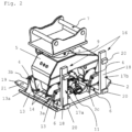
- the lifting forks 16 are reattached to a forklift truck so that the truck can lift the add-on compactor 1 from the bed of the truck and place it on the ground.
- the retaining elements 19 of the fork tines 17a, 17b are pulled out of the recesses 6.
- the attachment compactor 1 is now attached to the excavator and used.
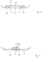
- Figure 5 shows a Figure 4 very similar embodiment, in which the length of the bracket 23 is however significantly shorter and therefore the two adjacent receiving sections 6 within a bracket 23 are significantly closer to each other.
Landscapes
- Engineering & Computer Science (AREA)
- Life Sciences & Earth Sciences (AREA)
- Structural Engineering (AREA)
- Mining & Mineral Resources (AREA)
- Civil Engineering (AREA)
- General Engineering & Computer Science (AREA)
- General Life Sciences & Earth Sciences (AREA)
- Textile Engineering (AREA)
- Environmental & Geological Engineering (AREA)
- Soil Sciences (AREA)
- Agronomy & Crop Science (AREA)
- Paleontology (AREA)
- Oceanography (AREA)
- Mechanical Engineering (AREA)
- Health & Medical Sciences (AREA)
- General Health & Medical Sciences (AREA)
- Physical Education & Sports Medicine (AREA)
- Road Paving Machines (AREA)
- Forklifts And Lifting Vehicles (AREA)
- Soil Working Implements (AREA)
Claims (5)
- Appareil de compactage du sol (1) avec un élément de compactage (2), présentant une première paire de sections de réception (6) espacées l'une de l'autre pour recevoir un premier élément de retenue rigide d'un moyen de transport sous la forme d'une première dent de fourche (19) d'une fourche de levage (16) et une deuxième paire de sections de réception (6) espacées l'une de l'autre pour recevoir un deuxième élément de retenue rigide d'un moyen de transport sous la forme d'une deuxième dent de fourche (19) d'une fourche de levage (16), dans lequel les sections de réception d'une paire sont formées par deux évidements (6) espacés l'un de l'autre et alignés axialement ou par deux zones espacées l'une de l'autre et alignées axialement d'un seul évidement (6), lesquels évidements (6) sont réalisés de telle sorte que la dent de fourche (19) respective de la fourche de levage (16) peut s'insérer dans celui-ci et dans lequel l'appareil de compactage du sol est un compacteur rapporté qui peut être accouplé à une pelle excavatrice (8) et dans lequel les évidements (6) présentent une forme rectangulaire, et dans lequel l'élément de compactage (2) est relié par des dispositifs de liaison (3a-3d) à une partie supérieure (5) de l'appareil de compactage du sol (1) et les sections de réception (6) sont réalisées dans au moins un dispositif de liaison (3a-3d) ou les sections de réception sont réalisées sur une partie supérieure de l'appareil de compactage du sol ou les sections de réception (6) sont disposées sur une face supérieure de l'élément de compactage (2).
- Appareil de compactage du sol (1) selon la revendication 1, caractérisé en ce que l'élément de compactage présente une plaque vibrante, une plaque de compactage (2) ou un rouleau.
- Appareil de compactage du sol (1) selon l'une quelconque des revendications précédentes, caractérisé en ce qu'il comprend au moins un adaptateur pouvant être inséré dans les évidements pour fermer les évidements (6) et/ou pour fixer des moyens de retenue (16) de conception différente.
- Appareil de compactage du sol (1) selon la revendication 1, caractérisé en ce qu'au moins un dispositif de liaison (3a-3b) présente une structure de support inférieure (13) qui est reliée à l'élément de compactage (2) et une structure de support supérieure (14) qui est reliée à la partie supérieure (5), et au moins un dispositif tampon (4) disposé entre la structure de support inférieure (13) et la structure de support supérieure (14), et en ce que les sections de réception (6) sont réalisées dans la structure de support inférieure et/ou supérieure (14).
- Appareil de compactage du sol selon l'une quelconque des revendications précédentes, caractérisé en ce que toutes les sections de réception (6) sont présentes dans un évidement (22) commun.
Applications Claiming Priority (2)
| Application Number | Priority Date | Filing Date | Title |
|---|---|---|---|
| DE102012210373A DE102012210373A1 (de) | 2012-06-20 | 2012-06-20 | Anbauverdichter |
| PCT/EP2013/057737 WO2013189622A2 (fr) | 2012-06-20 | 2013-04-12 | Appareil de compactage du sol |
Publications (3)
| Publication Number | Publication Date |
|---|---|
| EP2864548A2 EP2864548A2 (fr) | 2015-04-29 |
| EP2864548B1 EP2864548B1 (fr) | 2018-06-06 |
| EP2864548B2 true EP2864548B2 (fr) | 2025-07-09 |
Family
ID=48143280
Family Applications (1)
| Application Number | Title | Priority Date | Filing Date |
|---|---|---|---|
| EP13717758.0A Active EP2864548B2 (fr) | 2012-06-20 | 2013-04-12 | Dispositif pour compaction d'un sol |
Country Status (3)
| Country | Link |
|---|---|
| EP (1) | EP2864548B2 (fr) |
| DE (2) | DE202012013346U1 (fr) |
| WO (1) | WO2013189622A2 (fr) |
Families Citing this family (7)
| Publication number | Priority date | Publication date | Assignee | Title |
|---|---|---|---|---|
| DE102017107351A1 (de) * | 2017-04-05 | 2018-10-11 | Mts Maschinentechnik Schrode Ag | Bodenrecycler |
| CN107700465B (zh) * | 2017-10-18 | 2018-09-18 | 北京中科拓达科技有限公司 | 一种通信网络建设装置 |
| DE102018110465A1 (de) * | 2018-05-02 | 2019-11-07 | Mts Maschinentechnik Schrode Ag | Anbauwerkzeugeinrichtung |
| DE102019106445A1 (de) * | 2019-03-13 | 2020-09-17 | Mts Maschinentechnik Schrode Ag | Baggeranbaugerät |
| CN110512676B (zh) * | 2019-08-22 | 2021-04-13 | 温州金茂建设有限公司 | 一种挖掘机用多功能前端连接器 |
| CN111101528B (zh) * | 2020-01-20 | 2025-08-22 | 徐工集团工程机械股份有限公司道路机械分公司 | 一种填土整平压实装置 |
| CN116397617B (zh) * | 2023-04-23 | 2025-09-02 | 广西交科集团有限公司 | 一种岩土工程地基处理用夯击加固装置 |
Citations (8)
| Publication number | Priority date | Publication date | Assignee | Title |
|---|---|---|---|---|
| US4545721A (en) † | 1982-05-07 | 1985-10-08 | Stig Pettersson | Combined lift fork and bucket device for attachment to a vehicle |
| US4995760A (en) † | 1987-03-13 | 1991-02-26 | Martin Probst | Scraping device for making a subgrade |
| JPH0615980Y2 (ja) † | 1988-07-26 | 1994-04-27 | 小松造機株式会社 | フォークリフト用コンパクタ |
| US5897286A (en) † | 1997-11-21 | 1999-04-27 | Whittaker; Howard E | Forklift pallet stop |
| EP1411174A2 (fr) † | 2002-10-15 | 2004-04-21 | Rammax Maschinenbau GmbH | Dispositif pour compacter le sol |
| EP1536068A2 (fr) † | 2003-11-26 | 2005-06-01 | MTS Gesellschaft für Maschinentechnik und Sonderbauten MBH | Compacteur pouvant être connecté à un excavateur |
| DE102007045489A1 (de) † | 2007-09-21 | 2009-04-02 | Btb Recycling-Hof Gmbh | Kippwassertank |
| DE102009042454A1 (de) † | 2009-09-23 | 2011-04-28 | Schenk Werkzeug- Und Maschinenbau Gmbh & Co. Kg | Gießbehälter zur Aufnahme von flüssigem Metall |
Family Cites Families (9)
| Publication number | Priority date | Publication date | Assignee | Title |
|---|---|---|---|---|
| DE2231404A1 (de) * | 1971-11-01 | 1973-05-03 | Allied Steel Tractor Prod Inc | Vibrations-verdichtungsvorrichtung |
| US5209331A (en) | 1991-03-13 | 1993-05-11 | M-B-W Inc. | Clutch construction |
| DE4311213A1 (de) | 1993-04-05 | 1994-10-06 | Heinz Schuett | Rüttelplatte |
| DE19629324C1 (de) | 1996-07-20 | 1997-10-16 | Wacker Werke Kg | Vibrationsplatte mit Besohlung |
| US7805865B2 (en) * | 2006-01-13 | 2010-10-05 | M-B-W, Inc. | Vibratory exciter unit for interchangeable connection to various vibratory tools |
| DE102006061398A1 (de) * | 2006-12-23 | 2008-06-26 | MTS Gesellschaft für Maschinentechnik und Sonderbauten mbH | Anbauverdichter |
| DE102008006889C5 (de) | 2008-01-31 | 2018-09-13 | Mts Maschinentechnik Schrode Ag | Verdichtervorrichtung |
| DE102008010461A1 (de) | 2008-02-21 | 2009-08-27 | Rammax Maschinenbau Gmbh | Verfahren zur Einstellung und/oder Begrenzung der Anpresskraft eines Anbauverdichters |
| DE102008025026A1 (de) | 2008-05-24 | 2009-11-26 | MTS Gesellschaft für Maschinentechnik und Sonderbauten mbH | Bagger-Zusatzgerät |
-
2012
- 2012-06-20 DE DE202012013346.2U patent/DE202012013346U1/de not_active Ceased
- 2012-06-20 DE DE102012210373A patent/DE102012210373A1/de active Pending
-
2013
- 2013-04-12 WO PCT/EP2013/057737 patent/WO2013189622A2/fr not_active Ceased
- 2013-04-12 EP EP13717758.0A patent/EP2864548B2/fr active Active
Patent Citations (8)
| Publication number | Priority date | Publication date | Assignee | Title |
|---|---|---|---|---|
| US4545721A (en) † | 1982-05-07 | 1985-10-08 | Stig Pettersson | Combined lift fork and bucket device for attachment to a vehicle |
| US4995760A (en) † | 1987-03-13 | 1991-02-26 | Martin Probst | Scraping device for making a subgrade |
| JPH0615980Y2 (ja) † | 1988-07-26 | 1994-04-27 | 小松造機株式会社 | フォークリフト用コンパクタ |
| US5897286A (en) † | 1997-11-21 | 1999-04-27 | Whittaker; Howard E | Forklift pallet stop |
| EP1411174A2 (fr) † | 2002-10-15 | 2004-04-21 | Rammax Maschinenbau GmbH | Dispositif pour compacter le sol |
| EP1536068A2 (fr) † | 2003-11-26 | 2005-06-01 | MTS Gesellschaft für Maschinentechnik und Sonderbauten MBH | Compacteur pouvant être connecté à un excavateur |
| DE102007045489A1 (de) † | 2007-09-21 | 2009-04-02 | Btb Recycling-Hof Gmbh | Kippwassertank |
| DE102009042454A1 (de) † | 2009-09-23 | 2011-04-28 | Schenk Werkzeug- Und Maschinenbau Gmbh & Co. Kg | Gießbehälter zur Aufnahme von flüssigem Metall |
Non-Patent Citations (6)
| Title |
|---|
| Betriebs- und Wartungsanweisung RAV 700-P,Rammax Maschinenbau GmbH, gültig ab 09/03 † |
| DIN 15173:1986-04 Gabelträger und Anbaugeräte für Stapler † |
| Fotos (Bild 1 bis Bild 4} RAV 700-P Masch.Nr.403 5638 † |
| Fotos (Seiten 1 bis 3) RAV 700-P † |
| Fotos (Seiten 1 bis 5) RAV 700-P † |
| Rechnung vom 31.05.2006 Seriennummer 403 5638 † |
Also Published As
| Publication number | Publication date |
|---|---|
| EP2864548A2 (fr) | 2015-04-29 |
| DE202012013346U1 (de) | 2016-06-22 |
| EP2864548B1 (fr) | 2018-06-06 |
| WO2013189622A2 (fr) | 2013-12-27 |
| WO2013189622A3 (fr) | 2014-02-20 |
| DE102012210373A1 (de) | 2013-12-24 |
Similar Documents
| Publication | Publication Date | Title |
|---|---|---|
| EP2864548B2 (fr) | Dispositif pour compaction d'un sol | |
| EP0538721B1 (fr) | Châssis pour véhicules chenillés | |
| DE3013513A1 (de) | Umruestbare maschine mit einem ausleger | |
| DE102015006117A1 (de) | Verfahren zum Betrieb eines Krans und Kran | |
| EP2620548B1 (fr) | Engin avec structure de cabine à oscillations découplées et dispositif d'attelage | |
| DE202021106818U1 (de) | Mobilkran mit einer Gegengewichtsvorrichtung | |
| DE102014012661B4 (de) | Verfahren zum Betrieb eines Krans und Kran | |
| DE102010035894A1 (de) | Anordnung zum Wenden einer Last | |
| EP2199247A2 (fr) | Liaison rotative | |
| DE202019106049U1 (de) | Schwerlast-Prüfgewichteinheit zur Belastungsprüfung von Krananlagen | |
| DE69231101T2 (de) | Verbindung des Untergestells eines Krans an die Raupenkette(n) | |
| EP4039633B1 (fr) | Châssis de véhicule à grue mobile pourvu de pièces amovibles de châssis | |
| EP0564403A1 (fr) | Dispositif de chargement et de déchargement d'un porte-charges sur un véhicule | |
| EP4317046B1 (fr) | Grue mobile dotée d'un dispositif de contrepoids réglable, dispositif de contrepoids et procédé de montage d'une telle grue | |
| DE102011119656B4 (de) | Fahrzeugkran | |
| DE102014008720A1 (de) | Schwerlastfahrzeug mit Staplerfunktion | |
| DE102023109566B4 (de) | Mobilkran mit Gegengewichtsvorrichtung, Gegengewichtsvorrichtung sowie Verfahren zur Montage einer solchen | |
| EP4311802B1 (fr) | Essieu de transport pour le transport d'une grue à tour et procédé de transport d'une grue à tour au moyen d'un essieu de transport | |
| EP1120376B1 (fr) | Machine de pose de conduites | |
| DE102014220132B4 (de) | Mobilkran und Verfahren zum Abstützen eines derartigen Mobilkrans | |
| DE102004042126A1 (de) | Sicherheitsstütze für Hubzylinder | |
| DE2737884A1 (de) | Betonpumpverteiler auf sattelfahrzeug | |
| DE10226319B4 (de) | Fahrzeugkran mit ein- und ausfahrbarer Koppeleinrichtung für ein Gegengewicht | |
| DE10061330B4 (de) | Kranfahrzeug mit zwei Hubwerken | |
| DE29912463U1 (de) | Greifvorrichtung |
Legal Events
| Date | Code | Title | Description |
|---|---|---|---|
| PUAI | Public reference made under article 153(3) epc to a published international application that has entered the european phase |
Free format text: ORIGINAL CODE: 0009012 |
|
| 17P | Request for examination filed |
Effective date: 20141128 |
|
| AK | Designated contracting states |
Kind code of ref document: A2 Designated state(s): AL AT BE BG CH CY CZ DE DK EE ES FI FR GB GR HR HU IE IS IT LI LT LU LV MC MK MT NL NO PL PT RO RS SE SI SK SM TR |
|
| AX | Request for extension of the european patent |
Extension state: BA ME |
|
| DAX | Request for extension of the european patent (deleted) | ||
| GRAP | Despatch of communication of intention to grant a patent |
Free format text: ORIGINAL CODE: EPIDOSNIGR1 |
|
| STAA | Information on the status of an ep patent application or granted ep patent |
Free format text: STATUS: GRANT OF PATENT IS INTENDED |
|
| INTG | Intention to grant announced |
Effective date: 20171222 |
|
| GRAS | Grant fee paid |
Free format text: ORIGINAL CODE: EPIDOSNIGR3 |
|
| GRAA | (expected) grant |
Free format text: ORIGINAL CODE: 0009210 |
|
| STAA | Information on the status of an ep patent application or granted ep patent |
Free format text: STATUS: THE PATENT HAS BEEN GRANTED |
|
| AK | Designated contracting states |
Kind code of ref document: B1 Designated state(s): AL AT BE BG CH CY CZ DE DK EE ES FI FR GB GR HR HU IE IS IT LI LT LU LV MC MK MT NL NO PL PT RO RS SE SI SK SM TR |
|
| REG | Reference to a national code |
Ref country code: GB Ref legal event code: FG4D Free format text: NOT ENGLISH |
|
| REG | Reference to a national code |
Ref country code: CH Ref legal event code: EP Ref country code: AT Ref legal event code: REF Ref document number: 1006222 Country of ref document: AT Kind code of ref document: T Effective date: 20180615 |
|
| REG | Reference to a national code |
Ref country code: IE Ref legal event code: FG4D Free format text: LANGUAGE OF EP DOCUMENT: GERMAN |
|
| REG | Reference to a national code |
Ref country code: DE Ref legal event code: R096 Ref document number: 502013010327 Country of ref document: DE |
|
| REG | Reference to a national code |
Ref country code: NL Ref legal event code: MP Effective date: 20180606 |
|
| REG | Reference to a national code |
Ref country code: LT Ref legal event code: MG4D |
|
| PG25 | Lapsed in a contracting state [announced via postgrant information from national office to epo] |
Ref country code: FI Free format text: LAPSE BECAUSE OF FAILURE TO SUBMIT A TRANSLATION OF THE DESCRIPTION OR TO PAY THE FEE WITHIN THE PRESCRIBED TIME-LIMIT Effective date: 20180606 Ref country code: NO Free format text: LAPSE BECAUSE OF FAILURE TO SUBMIT A TRANSLATION OF THE DESCRIPTION OR TO PAY THE FEE WITHIN THE PRESCRIBED TIME-LIMIT Effective date: 20180906 Ref country code: LT Free format text: LAPSE BECAUSE OF FAILURE TO SUBMIT A TRANSLATION OF THE DESCRIPTION OR TO PAY THE FEE WITHIN THE PRESCRIBED TIME-LIMIT Effective date: 20180606 Ref country code: ES Free format text: LAPSE BECAUSE OF FAILURE TO SUBMIT A TRANSLATION OF THE DESCRIPTION OR TO PAY THE FEE WITHIN THE PRESCRIBED TIME-LIMIT Effective date: 20180606 Ref country code: SE Free format text: LAPSE BECAUSE OF FAILURE TO SUBMIT A TRANSLATION OF THE DESCRIPTION OR TO PAY THE FEE WITHIN THE PRESCRIBED TIME-LIMIT Effective date: 20180606 Ref country code: CY Free format text: LAPSE BECAUSE OF FAILURE TO SUBMIT A TRANSLATION OF THE DESCRIPTION OR TO PAY THE FEE WITHIN THE PRESCRIBED TIME-LIMIT Effective date: 20180606 Ref country code: BG Free format text: LAPSE BECAUSE OF FAILURE TO SUBMIT A TRANSLATION OF THE DESCRIPTION OR TO PAY THE FEE WITHIN THE PRESCRIBED TIME-LIMIT Effective date: 20180906 |
|
| PG25 | Lapsed in a contracting state [announced via postgrant information from national office to epo] |
Ref country code: LV Free format text: LAPSE BECAUSE OF FAILURE TO SUBMIT A TRANSLATION OF THE DESCRIPTION OR TO PAY THE FEE WITHIN THE PRESCRIBED TIME-LIMIT Effective date: 20180606 Ref country code: RS Free format text: LAPSE BECAUSE OF FAILURE TO SUBMIT A TRANSLATION OF THE DESCRIPTION OR TO PAY THE FEE WITHIN THE PRESCRIBED TIME-LIMIT Effective date: 20180606 Ref country code: GR Free format text: LAPSE BECAUSE OF FAILURE TO SUBMIT A TRANSLATION OF THE DESCRIPTION OR TO PAY THE FEE WITHIN THE PRESCRIBED TIME-LIMIT Effective date: 20180907 Ref country code: HR Free format text: LAPSE BECAUSE OF FAILURE TO SUBMIT A TRANSLATION OF THE DESCRIPTION OR TO PAY THE FEE WITHIN THE PRESCRIBED TIME-LIMIT Effective date: 20180606 |
|
| PG25 | Lapsed in a contracting state [announced via postgrant information from national office to epo] |
Ref country code: NL Free format text: LAPSE BECAUSE OF FAILURE TO SUBMIT A TRANSLATION OF THE DESCRIPTION OR TO PAY THE FEE WITHIN THE PRESCRIBED TIME-LIMIT Effective date: 20180606 |
|
| PG25 | Lapsed in a contracting state [announced via postgrant information from national office to epo] |
Ref country code: IS Free format text: LAPSE BECAUSE OF FAILURE TO SUBMIT A TRANSLATION OF THE DESCRIPTION OR TO PAY THE FEE WITHIN THE PRESCRIBED TIME-LIMIT Effective date: 20181006 Ref country code: EE Free format text: LAPSE BECAUSE OF FAILURE TO SUBMIT A TRANSLATION OF THE DESCRIPTION OR TO PAY THE FEE WITHIN THE PRESCRIBED TIME-LIMIT Effective date: 20180606 Ref country code: PL Free format text: LAPSE BECAUSE OF FAILURE TO SUBMIT A TRANSLATION OF THE DESCRIPTION OR TO PAY THE FEE WITHIN THE PRESCRIBED TIME-LIMIT Effective date: 20180606 Ref country code: SK Free format text: LAPSE BECAUSE OF FAILURE TO SUBMIT A TRANSLATION OF THE DESCRIPTION OR TO PAY THE FEE WITHIN THE PRESCRIBED TIME-LIMIT Effective date: 20180606 Ref country code: CZ Free format text: LAPSE BECAUSE OF FAILURE TO SUBMIT A TRANSLATION OF THE DESCRIPTION OR TO PAY THE FEE WITHIN THE PRESCRIBED TIME-LIMIT Effective date: 20180606 Ref country code: RO Free format text: LAPSE BECAUSE OF FAILURE TO SUBMIT A TRANSLATION OF THE DESCRIPTION OR TO PAY THE FEE WITHIN THE PRESCRIBED TIME-LIMIT Effective date: 20180606 |
|
| PG25 | Lapsed in a contracting state [announced via postgrant information from national office to epo] |
Ref country code: IT Free format text: LAPSE BECAUSE OF FAILURE TO SUBMIT A TRANSLATION OF THE DESCRIPTION OR TO PAY THE FEE WITHIN THE PRESCRIBED TIME-LIMIT Effective date: 20180606 Ref country code: SM Free format text: LAPSE BECAUSE OF FAILURE TO SUBMIT A TRANSLATION OF THE DESCRIPTION OR TO PAY THE FEE WITHIN THE PRESCRIBED TIME-LIMIT Effective date: 20180606 |
|
| REG | Reference to a national code |
Ref country code: DE Ref legal event code: R026 Ref document number: 502013010327 Country of ref document: DE |
|
| PLBI | Opposition filed |
Free format text: ORIGINAL CODE: 0009260 |
|
| PLAX | Notice of opposition and request to file observation + time limit sent |
Free format text: ORIGINAL CODE: EPIDOSNOBS2 |
|
| 26 | Opposition filed |
Opponent name: HELMUT UHRIG STRASSEN- UND TIEFBAU GMBH Effective date: 20190305 |
|
| PG25 | Lapsed in a contracting state [announced via postgrant information from national office to epo] |
Ref country code: DK Free format text: LAPSE BECAUSE OF FAILURE TO SUBMIT A TRANSLATION OF THE DESCRIPTION OR TO PAY THE FEE WITHIN THE PRESCRIBED TIME-LIMIT Effective date: 20180606 Ref country code: SI Free format text: LAPSE BECAUSE OF FAILURE TO SUBMIT A TRANSLATION OF THE DESCRIPTION OR TO PAY THE FEE WITHIN THE PRESCRIBED TIME-LIMIT Effective date: 20180606 |
|
| PLBB | Reply of patent proprietor to notice(s) of opposition received |
Free format text: ORIGINAL CODE: EPIDOSNOBS3 |
|
| PGFP | Annual fee paid to national office [announced via postgrant information from national office to epo] |
Ref country code: GB Payment date: 20190411 Year of fee payment: 7 |
|
| PG25 | Lapsed in a contracting state [announced via postgrant information from national office to epo] |
Ref country code: AL Free format text: LAPSE BECAUSE OF FAILURE TO SUBMIT A TRANSLATION OF THE DESCRIPTION OR TO PAY THE FEE WITHIN THE PRESCRIBED TIME-LIMIT Effective date: 20180606 |
|
| REG | Reference to a national code |
Ref country code: BE Ref legal event code: MM Effective date: 20190430 |
|
| PG25 | Lapsed in a contracting state [announced via postgrant information from national office to epo] |
Ref country code: LU Free format text: LAPSE BECAUSE OF NON-PAYMENT OF DUE FEES Effective date: 20190412 Ref country code: MC Free format text: LAPSE BECAUSE OF FAILURE TO SUBMIT A TRANSLATION OF THE DESCRIPTION OR TO PAY THE FEE WITHIN THE PRESCRIBED TIME-LIMIT Effective date: 20180606 |
|
| PG25 | Lapsed in a contracting state [announced via postgrant information from national office to epo] |
Ref country code: BE Free format text: LAPSE BECAUSE OF NON-PAYMENT OF DUE FEES Effective date: 20190430 |
|
| PG25 | Lapsed in a contracting state [announced via postgrant information from national office to epo] |
Ref country code: TR Free format text: LAPSE BECAUSE OF FAILURE TO SUBMIT A TRANSLATION OF THE DESCRIPTION OR TO PAY THE FEE WITHIN THE PRESCRIBED TIME-LIMIT Effective date: 20180606 |
|
| PG25 | Lapsed in a contracting state [announced via postgrant information from national office to epo] |
Ref country code: IE Free format text: LAPSE BECAUSE OF NON-PAYMENT OF DUE FEES Effective date: 20190412 |
|
| PG25 | Lapsed in a contracting state [announced via postgrant information from national office to epo] |
Ref country code: PT Free format text: LAPSE BECAUSE OF FAILURE TO SUBMIT A TRANSLATION OF THE DESCRIPTION OR TO PAY THE FEE WITHIN THE PRESCRIBED TIME-LIMIT Effective date: 20181008 |
|
| RAP2 | Party data changed (patent owner data changed or rights of a patent transferred) |
Owner name: MTS SCHRODE AG |
|
| REG | Reference to a national code |
Ref country code: DE Ref legal event code: R082 Ref document number: 502013010327 Country of ref document: DE Representative=s name: DREISS PATENTANWAELTE PARTG MBB, DE Ref country code: DE Ref legal event code: R081 Ref document number: 502013010327 Country of ref document: DE Owner name: MTS SCHRODE AG, DE Free format text: FORMER OWNER: MTS MASCHINENTECHNIK SCHRODE AG, 72534 HAYINGEN, DE |
|
| GBPC | Gb: european patent ceased through non-payment of renewal fee |
Effective date: 20200412 |
|
| REG | Reference to a national code |
Ref country code: CH Ref legal event code: PFA Owner name: MTS SCHRODE AG, DE Free format text: FORMER OWNER: MTS MASCHINENTECHNIK SCHRODE AG, DE |
|
| PG25 | Lapsed in a contracting state [announced via postgrant information from national office to epo] |
Ref country code: GB Free format text: LAPSE BECAUSE OF NON-PAYMENT OF DUE FEES Effective date: 20200412 |
|
| PG25 | Lapsed in a contracting state [announced via postgrant information from national office to epo] |
Ref country code: HU Free format text: LAPSE BECAUSE OF FAILURE TO SUBMIT A TRANSLATION OF THE DESCRIPTION OR TO PAY THE FEE WITHIN THE PRESCRIBED TIME-LIMIT; INVALID AB INITIO Effective date: 20130412 Ref country code: MT Free format text: LAPSE BECAUSE OF FAILURE TO SUBMIT A TRANSLATION OF THE DESCRIPTION OR TO PAY THE FEE WITHIN THE PRESCRIBED TIME-LIMIT Effective date: 20180606 |
|
| REG | Reference to a national code |
Ref country code: AT Ref legal event code: HC Ref document number: 1006222 Country of ref document: AT Kind code of ref document: T Owner name: MTS SCHRODE AG, DE Effective date: 20210705 |
|
| PG25 | Lapsed in a contracting state [announced via postgrant information from national office to epo] |
Ref country code: MK Free format text: LAPSE BECAUSE OF FAILURE TO SUBMIT A TRANSLATION OF THE DESCRIPTION OR TO PAY THE FEE WITHIN THE PRESCRIBED TIME-LIMIT Effective date: 20180606 |
|
| APBM | Appeal reference recorded |
Free format text: ORIGINAL CODE: EPIDOSNREFNO |
|
| APBP | Date of receipt of notice of appeal recorded |
Free format text: ORIGINAL CODE: EPIDOSNNOA2O |
|
| APAH | Appeal reference modified |
Free format text: ORIGINAL CODE: EPIDOSCREFNO |
|
| APBM | Appeal reference recorded |
Free format text: ORIGINAL CODE: EPIDOSNREFNO |
|
| APBP | Date of receipt of notice of appeal recorded |
Free format text: ORIGINAL CODE: EPIDOSNNOA2O |
|
| APBQ | Date of receipt of statement of grounds of appeal recorded |
Free format text: ORIGINAL CODE: EPIDOSNNOA3O |
|
| APBQ | Date of receipt of statement of grounds of appeal recorded |
Free format text: ORIGINAL CODE: EPIDOSNNOA3O |
|
| PGFP | Annual fee paid to national office [announced via postgrant information from national office to epo] |
Ref country code: AT Payment date: 20240417 Year of fee payment: 12 |
|
| APBU | Appeal procedure closed |
Free format text: ORIGINAL CODE: EPIDOSNNOA9O |
|
| PUAH | Patent maintained in amended form |
Free format text: ORIGINAL CODE: 0009272 |
|
| REG | Reference to a national code |
Ref country code: DE Ref legal event code: R039 Ref document number: 502013010327 Country of ref document: DE Ref country code: DE Ref legal event code: R008 Ref document number: 502013010327 Country of ref document: DE |
|
| STAA | Information on the status of an ep patent application or granted ep patent |
Free format text: STATUS: PATENT MAINTAINED AS AMENDED |
|
| 27A | Patent maintained in amended form |
Effective date: 20250709 |
|
| AK | Designated contracting states |
Kind code of ref document: B2 Designated state(s): AL AT BE BG CH CY CZ DE DK EE ES FI FR GB GR HR HU IE IS IT LI LT LU LV MC MK MT NL NO PL PT RO RS SE SI SK SM TR |
|
| PGFP | Annual fee paid to national office [announced via postgrant information from national office to epo] |
Ref country code: DE Payment date: 20250611 Year of fee payment: 13 |
|
| REG | Reference to a national code |
Ref country code: DE Ref legal event code: R102 Ref document number: 502013010327 Country of ref document: DE |
|
| PGFP | Annual fee paid to national office [announced via postgrant information from national office to epo] |
Ref country code: FR Payment date: 20250425 Year of fee payment: 13 |
|
| PGFP | Annual fee paid to national office [announced via postgrant information from national office to epo] |
Ref country code: CH Payment date: 20250501 Year of fee payment: 13 |
|
| REG | Reference to a national code |
Ref country code: AT Ref legal event code: MM01 Ref document number: 1006222 Country of ref document: AT Kind code of ref document: T Effective date: 20250412 |
|
| PG25 | Lapsed in a contracting state [announced via postgrant information from national office to epo] |
Ref country code: AT Free format text: LAPSE BECAUSE OF NON-PAYMENT OF DUE FEES Effective date: 20250412 |