EP2862725B1 - Sportausrüstung - Google Patents
Sportausrüstung Download PDFInfo
- Publication number
- EP2862725B1 EP2862725B1 EP14180953.3A EP14180953A EP2862725B1 EP 2862725 B1 EP2862725 B1 EP 2862725B1 EP 14180953 A EP14180953 A EP 14180953A EP 2862725 B1 EP2862725 B1 EP 2862725B1
- Authority
- EP
- European Patent Office
- Prior art keywords
- layer
- metallic material
- adhesive layer
- decorative
- material layer
- Prior art date
- Legal status (The legal status is an assumption and is not a legal conclusion. Google has not performed a legal analysis and makes no representation as to the accuracy of the status listed.)
- Active
Links
Images




Classifications
-
- A—HUMAN NECESSITIES
- A63—SPORTS; GAMES; AMUSEMENTS
- A63B—APPARATUS FOR PHYSICAL TRAINING, GYMNASTICS, SWIMMING, CLIMBING, OR FENCING; BALL GAMES; TRAINING EQUIPMENT
- A63B49/00—Stringed rackets, e.g. for tennis
- A63B49/02—Frames
- A63B49/12—Frames made of metal
-
- A—HUMAN NECESSITIES
- A63—SPORTS; GAMES; AMUSEMENTS
- A63B—APPARATUS FOR PHYSICAL TRAINING, GYMNASTICS, SWIMMING, CLIMBING, OR FENCING; BALL GAMES; TRAINING EQUIPMENT
- A63B49/00—Stringed rackets, e.g. for tennis
- A63B49/02—Frames
- A63B49/08—Frames with special construction of the handle
-
- B—PERFORMING OPERATIONS; TRANSPORTING
- B32—LAYERED PRODUCTS
- B32B—LAYERED PRODUCTS, i.e. PRODUCTS BUILT-UP OF STRATA OF FLAT OR NON-FLAT, e.g. CELLULAR OR HONEYCOMB, FORM
- B32B7/00—Layered products characterised by the relation between layers; Layered products characterised by the relative orientation of features between layers, or by the relative values of a measurable parameter between layers, i.e. products comprising layers having different physical, chemical or physicochemical properties; Layered products characterised by the interconnection of layers
- B32B7/04—Interconnection of layers
- B32B7/12—Interconnection of layers using interposed adhesives or interposed materials with bonding properties
-
- A—HUMAN NECESSITIES
- A01—AGRICULTURE; FORESTRY; ANIMAL HUSBANDRY; HUNTING; TRAPPING; FISHING
- A01K—ANIMAL HUSBANDRY; AVICULTURE; APICULTURE; PISCICULTURE; FISHING; REARING OR BREEDING ANIMALS, NOT OTHERWISE PROVIDED FOR; NEW BREEDS OF ANIMALS
- A01K85/00—Artificial bait for fishing
- A01K85/16—Artificial bait for fishing with other than flat, or substantially flat, undulating bodies, e.g. plugs
-
- A—HUMAN NECESSITIES
- A01—AGRICULTURE; FORESTRY; ANIMAL HUSBANDRY; HUNTING; TRAPPING; FISHING
- A01K—ANIMAL HUSBANDRY; AVICULTURE; APICULTURE; PISCICULTURE; FISHING; REARING OR BREEDING ANIMALS, NOT OTHERWISE PROVIDED FOR; NEW BREEDS OF ANIMALS
- A01K87/00—Fishing rods
-
- B—PERFORMING OPERATIONS; TRANSPORTING
- B32—LAYERED PRODUCTS
- B32B—LAYERED PRODUCTS, i.e. PRODUCTS BUILT-UP OF STRATA OF FLAT OR NON-FLAT, e.g. CELLULAR OR HONEYCOMB, FORM
- B32B15/00—Layered products comprising a layer of metal
- B32B15/04—Layered products comprising a layer of metal comprising metal as the main or only constituent of a layer, which is next to another layer of the same or of a different material
- B32B15/08—Layered products comprising a layer of metal comprising metal as the main or only constituent of a layer, which is next to another layer of the same or of a different material of synthetic resin
-
- B—PERFORMING OPERATIONS; TRANSPORTING
- B32—LAYERED PRODUCTS
- B32B—LAYERED PRODUCTS, i.e. PRODUCTS BUILT-UP OF STRATA OF FLAT OR NON-FLAT, e.g. CELLULAR OR HONEYCOMB, FORM
- B32B15/00—Layered products comprising a layer of metal
- B32B15/04—Layered products comprising a layer of metal comprising metal as the main or only constituent of a layer, which is next to another layer of the same or of a different material
- B32B15/08—Layered products comprising a layer of metal comprising metal as the main or only constituent of a layer, which is next to another layer of the same or of a different material of synthetic resin
- B32B15/082—Layered products comprising a layer of metal comprising metal as the main or only constituent of a layer, which is next to another layer of the same or of a different material of synthetic resin comprising vinyl resins; comprising acrylic resins
-
- B—PERFORMING OPERATIONS; TRANSPORTING
- B32—LAYERED PRODUCTS
- B32B—LAYERED PRODUCTS, i.e. PRODUCTS BUILT-UP OF STRATA OF FLAT OR NON-FLAT, e.g. CELLULAR OR HONEYCOMB, FORM
- B32B15/00—Layered products comprising a layer of metal
- B32B15/04—Layered products comprising a layer of metal comprising metal as the main or only constituent of a layer, which is next to another layer of the same or of a different material
- B32B15/08—Layered products comprising a layer of metal comprising metal as the main or only constituent of a layer, which is next to another layer of the same or of a different material of synthetic resin
- B32B15/085—Layered products comprising a layer of metal comprising metal as the main or only constituent of a layer, which is next to another layer of the same or of a different material of synthetic resin comprising polyolefins
-
- B—PERFORMING OPERATIONS; TRANSPORTING
- B32—LAYERED PRODUCTS
- B32B—LAYERED PRODUCTS, i.e. PRODUCTS BUILT-UP OF STRATA OF FLAT OR NON-FLAT, e.g. CELLULAR OR HONEYCOMB, FORM
- B32B15/00—Layered products comprising a layer of metal
- B32B15/04—Layered products comprising a layer of metal comprising metal as the main or only constituent of a layer, which is next to another layer of the same or of a different material
- B32B15/08—Layered products comprising a layer of metal comprising metal as the main or only constituent of a layer, which is next to another layer of the same or of a different material of synthetic resin
- B32B15/09—Layered products comprising a layer of metal comprising metal as the main or only constituent of a layer, which is next to another layer of the same or of a different material of synthetic resin comprising polyesters
-
- B—PERFORMING OPERATIONS; TRANSPORTING
- B32—LAYERED PRODUCTS
- B32B—LAYERED PRODUCTS, i.e. PRODUCTS BUILT-UP OF STRATA OF FLAT OR NON-FLAT, e.g. CELLULAR OR HONEYCOMB, FORM
- B32B15/00—Layered products comprising a layer of metal
- B32B15/04—Layered products comprising a layer of metal comprising metal as the main or only constituent of a layer, which is next to another layer of the same or of a different material
- B32B15/08—Layered products comprising a layer of metal comprising metal as the main or only constituent of a layer, which is next to another layer of the same or of a different material of synthetic resin
- B32B15/092—Layered products comprising a layer of metal comprising metal as the main or only constituent of a layer, which is next to another layer of the same or of a different material of synthetic resin comprising epoxy resins
-
- B—PERFORMING OPERATIONS; TRANSPORTING
- B32—LAYERED PRODUCTS
- B32B—LAYERED PRODUCTS, i.e. PRODUCTS BUILT-UP OF STRATA OF FLAT OR NON-FLAT, e.g. CELLULAR OR HONEYCOMB, FORM
- B32B15/00—Layered products comprising a layer of metal
- B32B15/04—Layered products comprising a layer of metal comprising metal as the main or only constituent of a layer, which is next to another layer of the same or of a different material
- B32B15/08—Layered products comprising a layer of metal comprising metal as the main or only constituent of a layer, which is next to another layer of the same or of a different material of synthetic resin
- B32B15/095—Layered products comprising a layer of metal comprising metal as the main or only constituent of a layer, which is next to another layer of the same or of a different material of synthetic resin comprising polyurethanes
-
- B—PERFORMING OPERATIONS; TRANSPORTING
- B32—LAYERED PRODUCTS
- B32B—LAYERED PRODUCTS, i.e. PRODUCTS BUILT-UP OF STRATA OF FLAT OR NON-FLAT, e.g. CELLULAR OR HONEYCOMB, FORM
- B32B27/00—Layered products comprising a layer of synthetic resin
- B32B27/06—Layered products comprising a layer of synthetic resin as the main or only constituent of a layer, which is next to another layer of the same or of a different material
- B32B27/08—Layered products comprising a layer of synthetic resin as the main or only constituent of a layer, which is next to another layer of the same or of a different material of synthetic resin
-
- B—PERFORMING OPERATIONS; TRANSPORTING
- B32—LAYERED PRODUCTS
- B32B—LAYERED PRODUCTS, i.e. PRODUCTS BUILT-UP OF STRATA OF FLAT OR NON-FLAT, e.g. CELLULAR OR HONEYCOMB, FORM
- B32B27/00—Layered products comprising a layer of synthetic resin
- B32B27/30—Layered products comprising a layer of synthetic resin comprising vinyl (co)polymers; comprising acrylic (co)polymers
- B32B27/308—Layered products comprising a layer of synthetic resin comprising vinyl (co)polymers; comprising acrylic (co)polymers comprising acrylic (co)polymers
-
- B—PERFORMING OPERATIONS; TRANSPORTING
- B32—LAYERED PRODUCTS
- B32B—LAYERED PRODUCTS, i.e. PRODUCTS BUILT-UP OF STRATA OF FLAT OR NON-FLAT, e.g. CELLULAR OR HONEYCOMB, FORM
- B32B27/00—Layered products comprising a layer of synthetic resin
- B32B27/36—Layered products comprising a layer of synthetic resin comprising polyesters
-
- B—PERFORMING OPERATIONS; TRANSPORTING
- B32—LAYERED PRODUCTS
- B32B—LAYERED PRODUCTS, i.e. PRODUCTS BUILT-UP OF STRATA OF FLAT OR NON-FLAT, e.g. CELLULAR OR HONEYCOMB, FORM
- B32B27/00—Layered products comprising a layer of synthetic resin
- B32B27/38—Layered products comprising a layer of synthetic resin comprising epoxy resins
-
- B—PERFORMING OPERATIONS; TRANSPORTING
- B32—LAYERED PRODUCTS
- B32B—LAYERED PRODUCTS, i.e. PRODUCTS BUILT-UP OF STRATA OF FLAT OR NON-FLAT, e.g. CELLULAR OR HONEYCOMB, FORM
- B32B27/00—Layered products comprising a layer of synthetic resin
- B32B27/40—Layered products comprising a layer of synthetic resin comprising polyurethanes
-
- B—PERFORMING OPERATIONS; TRANSPORTING
- B32—LAYERED PRODUCTS
- B32B—LAYERED PRODUCTS, i.e. PRODUCTS BUILT-UP OF STRATA OF FLAT OR NON-FLAT, e.g. CELLULAR OR HONEYCOMB, FORM
- B32B3/00—Layered products comprising a layer with external or internal discontinuities or unevennesses, or a layer of non-planar shape; Layered products comprising a layer having particular features of form
- B32B3/26—Layered products comprising a layer with external or internal discontinuities or unevennesses, or a layer of non-planar shape; Layered products comprising a layer having particular features of form characterised by a particular shape of the outline of the cross-section of a continuous layer; characterised by a layer with cavities or internal voids ; characterised by an apertured layer
- B32B3/266—Layered products comprising a layer with external or internal discontinuities or unevennesses, or a layer of non-planar shape; Layered products comprising a layer having particular features of form characterised by a particular shape of the outline of the cross-section of a continuous layer; characterised by a layer with cavities or internal voids ; characterised by an apertured layer characterised by an apertured layer, the apertures going through the whole thickness of the layer, e.g. expanded metal, perforated layer, slit layer regular cells B32B3/12
-
- A—HUMAN NECESSITIES
- A63—SPORTS; GAMES; AMUSEMENTS
- A63B—APPARATUS FOR PHYSICAL TRAINING, GYMNASTICS, SWIMMING, CLIMBING, OR FENCING; BALL GAMES; TRAINING EQUIPMENT
- A63B71/00—Games or sports accessories not covered in groups A63B1/00 - A63B69/00
- A63B71/06—Indicating or scoring devices for games or players, or for other sports activities
- A63B2071/0694—Visual indication, e.g. Indicia
-
- A—HUMAN NECESSITIES
- A63—SPORTS; GAMES; AMUSEMENTS
- A63B—APPARATUS FOR PHYSICAL TRAINING, GYMNASTICS, SWIMMING, CLIMBING, OR FENCING; BALL GAMES; TRAINING EQUIPMENT
- A63B2209/00—Characteristics of used materials
-
- A—HUMAN NECESSITIES
- A63—SPORTS; GAMES; AMUSEMENTS
- A63B—APPARATUS FOR PHYSICAL TRAINING, GYMNASTICS, SWIMMING, CLIMBING, OR FENCING; BALL GAMES; TRAINING EQUIPMENT
- A63B49/00—Stringed rackets, e.g. for tennis
- A63B49/02—Frames
-
- B—PERFORMING OPERATIONS; TRANSPORTING
- B32—LAYERED PRODUCTS
- B32B—LAYERED PRODUCTS, i.e. PRODUCTS BUILT-UP OF STRATA OF FLAT OR NON-FLAT, e.g. CELLULAR OR HONEYCOMB, FORM
- B32B2307/00—Properties of the layers or laminate
- B32B2307/40—Properties of the layers or laminate having particular optical properties
Definitions
- the present invention relates to a sports equipment (e.g., fishing gears including fishing poles, golf clubs, and rackets) with a base member having printed thereon characters and/or decorative patterns by ink-jet printing using an ultraviolet (UV) curable resin (e.g., an UV ink), which cures upon irradiation with UV rays.
- a sports equipment e.g., fishing gears including fishing poles, golf clubs, and rackets
- an ultraviolet (UV) curable resin e.g., an UV ink
- the present invention relates to sports equipment having, on the surface, a decorative layer achieving three-dimensional and metallic appearance by using UV-curable resin.
- Ink for ink-jet printing used for such applications is categorized mainly into aqueous, oil-based, solvent-based and UV-curable ink.
- UV-curable ink has been adopted in various fields because its solventless, and quick-drying, and endurable natures enable printing on various materials such as glass, lumber, metal, plastic, and the like (see, e.g., Patent Literature 1 below).
- UV-curable ink has a property of significant viscosity change according to temperature.
- ink-jet nozzles suitable for ejecting such UV-curable ink may possibly be clogged with metallic powder having a large grain diameter and dispersedly included in the ink.
- metal flake pigment promotes initiation of polymerization of monomers or oligomers in UV-curable resin and, as such, short-term gelation occurs when the ink is in storage. Further, metallic shine of ink film of printed material using such ink tends to be lost by oxidization of the metal flake as time advances.
- the present invention is intended to overcome the above issues and one of the objects hereof is to provide sports equipment having, on the surface, a decorative layer which is able to sufficiently achieve three-dimensional and metallic appearance at low cost by ink-jet printing with ultraviolet-curable resin.
- the present invention is sports equipment having a base member and a decorative layer provided on a surface of the base member in a laminated state, wherein the decorative layer comprises a first adhesive layer of ultraviolet-curable resin formed into a first decorative shape by ink-jet printing a first metallic material layer adhered on the first adhesive layer, the first metallic material layer being formed into the first decorative shape a second adhesive layer of ultraviolet-curable resin disposed on the upper side of the first metallic material layer by ink-jet printing, the second adhesive layer being formed into a second decorative shape and a second metallic material layer adhered on the second adhesive layer, the second metallic material layer being formed into the second decorative shape wherein the first metallic material layer is exposed or visible through gaps between each dots of the ultraviolet-curable resin which forms the second adhesive layer.
- the decorative layer comprises a first adhesive layer of ultraviolet-curable resin formed into a first decorative shape by ink-jet printing a first metallic material layer adhered on the first adhesive layer, the first metallic material layer being formed into the first decorative shape a second adhesive layer of ultraviolet-curable resin
- the decorative layer is formed by layering at least two tuples of an adhesive layer of UV-curable resin provided by ink-jet printing and a metallic material layer adhered onto the adhesive layer.
- the decorative layer at least has a first tuple which comprises the first adhesive layer and the first metallic material layer and a second tuple which comprises the second adhesive layer and the second metallic material layer, and the number of the layered tuples is not limited.
- the first metallic material layer is exposed or visible through gaps between each dots of the ultraviolet-curable resin which forms the second adhesive layer. Accordingly, deep, three-dimensional, and metallic appearance can be achieved because at least two metallic material layers at different level can be observed in the same visual field.
- an adhesive layer of UV-curable resin ink-jet printed without UV-curable metallic ink and a different layer which is a metallic material layer adhered on the adhesive layer are layered and the lower layer which is the metallic material layer is made visible through the upper layer. Accordingly, deep, three-dimensional, and metallic appearance can be sufficiently achieved at low cost.
- “decoration” constitutes characters, lines, coloring, patterns (including colored patterns), or the combination hereof.
- a “decorative layer” includes a plurality of layers stacked together to form the decoration as a whole.
- a “dot” is each of droplets of resin which are ejected from ink-jet nozzles of an ink-jet printer and landed on the metallic material layers.
- the second decorative shape preferably differs from but may be the same as the first decorative shape, Different decorative shape may be, for example, the same in pattern (including characters) and different in coloring, or the same in coloring and different in pattern.
- a layer is exposed if the layer is completely open without any other layer thereon (naked).
- a layer is "visible” if the layer is visible through a transparent layer and the like.
- the decorative layer further comprises a third adhesive layer of UV-curable resin disposed on the upper side of the second metallic material layer, the third adhesive layer being formed into a third decorative shape by ink-jet printing and a third metallic material layer adhered on the third adhesive layer the third metallic material layer being formed into the third decorative shape wherein the second metallic material layer and/or the first metallic material layer are exposed or visible through gaps between each dots of UV-curable resin which forms the third adhesive layer.
- the third decorative shape preferably differs from but may be the same as the first and/or the second decorative shape.
- both the second metallic material layer and the first metallic material layer may be exposed or visible through gaps between dots of UV-curable resin which forms the third adhesive layer.
- either only the second metallic material layer or only the first metallic material layer may be exposed or visible through gaps between dots of UV-curable resin which forms the third adhesive layer.
- the layers which constitute the decorative layer may have any desirable thickness.
- the thicknesses of all the layers may be the same or the thicknesses of a part of or all the layers may be different.
- All or a part of the extending areas of the layers which constitute the decorative layer may be the same or may be different.
- the variation in thicknesses or extending areas of layers may contribute to the creation of three-dimensionality by a synergistic effect with the exposure or visibility of metallic materials in different layers described above.
- sports equipment having, on the surface, a decorative layer which is able to sufficiently achieve three-dimensional and metallic appearance at low cost by ink-jet printing with an ultraviolet-curable resin may be provided.
- Figs 1 , 2 and 3 show examples of the sports equipment:
- Fig. 1 schematically illustrates a lateral view of a pseudo bait for fishing (lure) having a decorative layer on the surface of a base member.
- Fig. 2 schematically illustrates a lateral view of a part of a fishing rod for fishing having a decorative layer on the surface of a base member.
- Fig. 3 schematically illustrates a tennis racket having a decorative layer on the surface of a base member.
- a lure 100 shown in Fig. 1 has a lure body 102 imitating a fish, a fishing line connection unit 106 which is provided in a head 102a of the lure body 102, and fishing hooks 104 which depend from an abdomen and a tail part of the lure body 102, wherein a decorative layer 20 decorated with scaled patterns is provided on a back of the lure body 102.
- the decorative layer 20 may be provided on a part other than the back of the lure body 102.
- a fishing rod 200 shown in Fig. 2 is, for example, a telescopic one and comprises a base rod 200a, a plurality of rods 200b, 200c,... being capable of telescoping within a base rod 200a.
- a base rod 200a is, for example, provided with the decorative layer 20 decorated with characters and patterns.
- the decorative layer 20 may be provided on rods which are other than the base rod 200a.
- a tennis racket 300 shown in Fig.3 has a shaft 302 provided with a grip 301 having a tape and the like wound therearound and a frame 306 extending from a tip of the shaft 302 and strung with a net (a gut) 305, wherein the shaft 302 is provided with the decorative layer 20 constituted by characters and patterns.
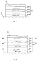
- Fig. 4 schematically illustrates a longitudinal sectional view of the layer structure of the decorative layer 20 according to the first embodiment of the present invention.
- the decorative layer 20 of the embodiment is provided on the surface of a base member 10 (e.g., a base member of the lure body 102 of the lure 100 in Fig.1 , a base member of the base rod 200a of the fishing rod 200 in Fig.2 , a base member of the shaft 302 of the tennis racket 300 and the like) in Fig. 3 in a layered or laminated state.
- a base member 10 e.g., a base member of the lure body 102 of the lure 100 in Fig.1 , a base member of the base rod 200a of the fishing rod 200 in Fig.2 , a base member of the shaft 302 of the tennis racket 300 and the like
- the decorative layer 20 comprises a first adhesive layer 22A of ultraviolet-curable resin formed into a first decorative shape by ink-jet printing, a first metallic material layer 24A adhered on the first adhesive layer 22A and formed into the first decorative shape, a second adhesive layer 22B of ultraviolet-curable resin disposed directly or across a certain transparent (colored or uncolored) layer on the upper side of the first metallic material layer by ink-jet printing, the second adhesive layer 22B being formed into a second decorative shape and a second metallic material layer 24B adhered on the second adhesive layer 22B, the second metallic material layer being 24B formed into the second decorative shape.
- the outermost layer 24B of the decorative layer 20 may be coated with uncolored or colored transparent layer 26 in the embodiment.
- This transparent layer 26 may be formed of a coating material including solvent (solvent ink) or UV-curable ink including UV-curable resin,
- a base member 10 may be formed of any of materials.
- Synthetic resin e.g., FRP, PP (PolyPropylene), PET (PolyEthylene Terephthalate), PC (PolyCarbonate), acrylic resin and the like can be adopted as a base member 10.
- One of the acrylic resins is PMMA (PolyMethyl MethAcrylate resin).
- Metal e.g., stainless steels, aluminum, alloys of copper, brasses and the like can be included other than the acrylic resins. Ceramics, glass, wares and the like which are inorganic can be adopted, too.
- the adhesive layers 22A, 22B may be an uncolored transparent layer or a colored transparent layer.
- UV-curable resin comprised by adhesive layers 22A, 22B is resin having adhesiveness of the type of curing by polymerization reaction by irradiation with ultraviolet rays.
- this UV-curable resin may comprise photopolimerizable oligomer and monomer (e.g., epoxy acrylate, urethane acrylate, polyester acrylate and the like) as a principle ingredient(s), pigment and an auxiliary material(s) such as an antifoaming agents and the like as well as a photopolymerization initiator as a catalytic agent.
- a photopolymerization initiator By irradiation with ultraviolet rays, a photopolymerization initiator generates radical, this radical initiates a polimerization of oligomer, and by this polymerization reaction, UV-curable resin cures and is fixed on a print target.
- photopolimerization initiators Benzophenone series, benzoin series, acetophenone series, thioxanthone series, acylphosphineoxide series and the like are generally adopted, although a various types of photopolymerization initiators exist.
- metallic material which is provided as metallic material layers 24A, 24B,..., for example, gold, silver, copper, platinum, aluminum, tin, brass and like may be included and especially, materials which are photoluminescent are preferable.
- decorative shapes of UV-curable resin which is provided as adhesive layers 22A, 22B are ink-jet printed on a base plate (material) 10 or the first metallic material layer 24A.
- An ink-jet printer (not shown) performing ink-jet printing has a recording head having a plurality of ejection nozzles and being reciprocal in scanning direction by a carriage and a light source for UV-curing which is equipped in the carriage.
- the light source is a mean to irradiation with ultraviolet rays and may adopt LED, for example. Adaptation of LED contributes to suppression of heat generation and saving energy.
- metal halide lamp, high pressure mercury lamp and the like as well as LED may be adopted as the light source.
- a droplet of UV-curable resin which constitutes the adhesive layer 22A or 22B is landed onto the base member 10 or the first metallic material layer 24A in a punctiform manner from the ejection nozzles of the recording head of the ink-jet printer.
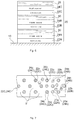
- resin dots 22b of the second adhesive layer 22B of the upper side are shown by solid lines and resin dots 22a of the first adhesive layer 22A of the lower side, are shown by dashed lines.
- resin dots 22a of the first adhesive layer 22A of the lower side are partially shown in Fig. 8 .
- a method to adhere metallic materials 24a, 24b in the same punctiform manner upon resin dots 22a, 22b by sticking and pushing a film of metallic foil onto the adhesive layer 22A, 22B, then ripping the film out may be, for example, adopted.
- the metallic material layers 24A, 24B are along the decorative figures of adhesive layers 22A, 22B (the decorative figures of a metallic material layers 24A, 24B are consistent with the decorative figures of the adhesive layers 22A, 22B).
- a method to spray metallic flakes onto the adhesive layers 22A, 22B may be, for example, adopted, but the disposition of metal is not limited.
- the first metallic material layer 24A of the lower side (the metallic material 24a of the first metallic material layer 24A which is adhered on resin dots 22a of the first adhesive layer 22A which is shown by the dashed lines) is exposed (as mentioned below, visible in the case that a transparent layer lies between the first metallic material layer 24A and the second adhesive layer 22B) through gaps S between each dots 22b, 22b (shown by the solid lines) of UV-curable resin which forms the second adhesive layer 22B.
- the decorative layer 20 in the embodiment is provided by layering or laminating at least two tuples of the adhesive layer 22A(22B) of UV-curable resin provided by ink-jet printing and the metallic material layer 24A(24B) adhered onto the adhesive layer 22A(22B), wherein the first metallic material layer 24A is exposed or visible through gaps S between each dots 22b, 22b of UV-curable resin which forms the second adhesive layer 22B.
- the decorative layer 20 may achieve deep and three-dimensional metallic appearance because at least the two metallic material layers 24A, 24B, which are different from each other, may be observed in the same visual field.
- the decorative layer 20 mentioned above is provided by layering or laminating the adhesive layers 22A (22B) of ink-jet printed UV-curable resin and the different layers which are the metallic material layers 24A (24B) adhered on the adhesive layers 22A (22B) and by making the lower layer which is the metallic material layer 24A visible from the upper layers. Accordingly deep and three-dimensional metallic appearance may be sufficiently achieved at low cost.
- Fig. 5 schematically illustrates a longitudinal sectional view of the layer structure of the decorative layer 20 according to the second embodiment of the present invention.
- the decorative layer 20 in the embodiment has a third adhesive layer 22C of UV-curable resin disposed directly or, in some embodiment, across a certain transparent layer on the upper side of the second metallic material layer 24B of the decorative layer 20 in the first embodiment shown in Fig. 4 and, further, formed into a third decorative shape by ink-jet printing and a third metallic material layer 24C adhered on the third adhesive layer 22C and formed into a third decorative shape, wherein the third metallic material layer 24C is coated with an uncolored or colored transparent layer 26.
- materials which constitute each layers and means of layering or laminating is the same as ones of the first embodiment (in the case of the third embodiment and on, the same as the first embodiment).
- gaps S' in other words, intervals between each dots 22c, 22c of the UV-curable resin which forms the third adhesive layer 22C is configured to be greater than gaps S, in other words, intervals between each dots 22a, 22a and/or each dots 22b, 22b of UV curable-resin which forms the second adhesive layer 22B and/or the first adhesive layer 22A, as shown by comparing Fig. 8 with Fig. 7 .
- Fig. 8 and 7 are the cross-sectional views along with the A-A line in Fig. 5 and along the B-B line in Fig. 5 each. In Fig.
- resin dots 22c of the third adhesive layer of the upper side are shown by solid lines as well as resin dots 22a, 22b of the first and second adhesive layers of the lower side is partially shown by dashed lines.
- such difference of intervals between dots arises, for example, by differing, amongst layers 22C, 22B, (22A), amount of resin ejected on printing (ratio for all the ejection area).
- the second metallic material layer 24B of the lower side metallic material 24b of the second metallic material layer 24B adhered onto resin dots 22b of the second adhesive layer shown by dashed lines
- the first metallic material layer 24A metallic material 24a of the first metallic material layer 24A adhered onto resin dots 22a of the first adhesive layer 22A shown by dashed lines
- intervals between resin dots of an upper adhesive layer may be configured to be greater than one of a lower adhesive layer as the embodiment.
- a lower metallic material may be also observed through gaps of an adhesive layer by shifting the positions of resin dots of an upper layer from the positions of resin dots of a lower layer or, as mentioned below, by providing an resin opening area (a hole and the like) in an adhesive layer.
- Fig. 6 schematically illustrates a longitudinal sectional view of the layer structure of the decorative layer 20 according to the third embodiment of the present invention.
- the decorative layer (20) of the embodiment is one of the variations of the decorative layer 20 of the second embodiment shown in Fig. 5 .
- a colored or uncolored transparent layer 30 lies between the first metallic material layer 24A and the second adhesive layer 22B and a colored or uncolored transparent layer 30 lies between the second metallic material layer 24B and the third adhesive layer 22C.
- the lying transparent layer 30 may be a coating material comprising solvent. To avoid position shifts by flow of a solvent, UV-curable ink and the like comprising UV-curable resin may be preferable.
- Other configurations are the same as the decorative layer 20 of the second embodiment shown in Fig 5 .
- Fig. 9 schematically illustrates a longitudinal sectional view of the layer structure of the decorative layer 20 according to the fourth embodiment of the present invention.
- the second adhesive layer 22A may be disposed all over upon the first metallic material layer 24A.
- the second adhesive layer 22B (accordingly the second metallic material layer, too), is disposed all over upon a partial upper side of the first metallic material layer 24A.
- a stage 40 is formed between the second adhesive layer 22B and the first metallic material layer 24A.
- the transparent layer (colored or uncolored) 26 with which the second metallic material layer 24B is coated covers not only the second metallic material layer 24B but also all over the decorative layer 20.
- Other configurations are the same as the decorative layer 20 of the first embodiment shown in Fig 4 .
- Fig. 10 schematically illustrates a longitudinal sectional view of the layer structure of the decorative layer 20 according to the fifth embodiment of the present invention.
- the decorative layer 20 of the embodiment is one of the variations of the decorative layer 20 of the first embodiment shown in Fig. 4 .
- the second adhesive layer 22B (accordingly the second metallic material layer, too), is disposed all over upon not a whole but a partial upper side of the first metallic material layer 24A.
- a stage 40 is formed between the second adhesive layer 22B and the first metallic material layer 24A.
- the colored or uncolored transparent layer 30 lies between the first metallic material layer 24A and the second adhesive layer 22B.
- Other configurations are the same as the decorative layer 20 of the first embodiment shown in Fig 4 .
- Fig. 11 schematically illustrates a longitudinal sectional view of the layer structure of the decorative layer 20 according to the sixth embodiment of the present invention.
- the decorative layer 20 of the embodiment is one of the variations of the decorative layer 20 of the second embodiment shown in Fig. 5 .
- the second adhesive layer 22B (accordingly, the second metallic material layer 24B, the third adhesive layer 22C and the third metallic material layer 24C, too) is disposed all over upon not a whole but a partial upper side of the first metallic material layer 24A.
- a stage 40 is formed between the second adhesive layer 22B and the first metallic material layer 24A.
- the transparent layer 26 with which the third metallic material layer 24C is coated covers not only the third metallic material layer 24C but also whole decorative layer 20.
- Other configurations are the same as the decorative layer 20 of the second embodiment shown in Fig 5 .
- Fig. 12 schematically illustrates a longitudinal sectional view of the layer structure of the decorative layer 20 according to the seventh embodiment of the present invention.
- the decorative layer 20 of this embodiment is one of the variations of the decorative layer 20 of the first embodiment shown in Fig. 4 .
- the second adhesive layer 22B has an opening area 22s, e.g., a hole or cutout, as part of its resin.
- the second metallic material layer 24B also has an opening area 24s which corresponds to the opening area 22s, and which has no metallic material.
- the first metallic material layer 24A is exposed through the opening area 22s (visible through the transparent layer 26). In this case, the opening area 22s may form a certain decorative shape.
- Other configurations are the same as the decorative layer 20 of the first embodiment shown in Fig 4 .
- Fig. 13 schematically illustrates a longitudinal sectional view of the layer structure of the decorative layer 20 according to the eighth embodiment of the present invention.
- the decorative layer 20 of the embodiment is one of the variations of the decorative layer 20 of the seventh embodiment shown in Fig. 12 .
- the (colored or uncolored) transparent layer 30 lies between the first metallic material layer 24A and the second adhesive layer 22B.
- Other configurations are the same as the decorative layer 20 of the eighth embodiment shown in Fig 13 .
- Embodiments of the present invention are not limited to the above descriptions and are susceptible to various modifications within the purport of the present invention.
- the number of layers in the decorative layers 20 described above may differ among the embodiments or may be the same among the embodiments.
- the decorative layer 20 may be provided all over or partly on the base member 10.
- the opening area described above may be provided with the third adhesive layer together with or as well as the second adhesive layer. In this case, the opening area itself may form a decorative shape.
- the third adhesive layer may be provided all over on a part of upper side of the second metallic material layer.
Landscapes
- Life Sciences & Earth Sciences (AREA)
- Environmental Sciences (AREA)
- Marine Sciences & Fisheries (AREA)
- Animal Husbandry (AREA)
- Biodiversity & Conservation Biology (AREA)
- Health & Medical Sciences (AREA)
- General Health & Medical Sciences (AREA)
- Physical Education & Sports Medicine (AREA)
- Laminated Bodies (AREA)
- Fishing Rods (AREA)
- Golf Clubs (AREA)
Claims (9)
- Sportequipment, welches ein Basiselement und eine dekorative Schicht aufweist, welche an einer Fläche des Basiselements in einem lamintierten Zustand bereitgestellt ist,
wobei die dekorative Schicht umfasst:eine erste adhäsive Schicht eines Ultraviolett-härtbaren Harzes, welche durch Tintenstrahldrucken in eine erste dekorative Form gebildet ist;eine erste metallische Materialschicht, welche an der ersten adhäsiven Schicht angebracht ist, wobei die erste metallische Materialschicht in die erste dekorative Form gebildet ist;eine zweite adhäsive Schicht eines Ultraviolett-härtbaren Harzes, welche an der oberen Seite der ersten metallischen Materialschicht durch Tintenstrahldrucken angeordnet ist, wobei die zweite adhäsive Schicht in eine zweite dekorative Form gebildet ist; undeine zweite metallische Materialschicht, welche an der zweiten adhäsiven Schicht angebracht ist, wobei die zweite metallische Materialschicht in die zweite dekorative Form gebildet ist;wobei die erste metallische Materialschicht durch Spalte zwischen jeden Punkten des Ultraviolett-härtbaren Harzes freigelegt oder sichtbar ist, welches die zweite adhäsive Schicht bildet. - Sportequipment nach Anspruch 1, wobei eine transparente Schicht zwischen der ersten metallischen Materialschicht und der zweiten adhäsiven Schicht liegt.
- Sportequipment nach einem der Ansprüche 1 und 2, wobei die zweite adhäsive Schicht teilweise einen Öffnungsbereich aufweist, und wobei die erste metallische Materialschicht durch den Öffnungsbereich freigelegt oder sichtbar ist.
- Sportequipment nach Anspruch 3, wobei der Öffnungsbereich eine dekorative Form bildet.
- Sportequipment nach einem der Ansprüche 1 bis 4, wobei die zweite adhäsive Schicht an der teilweisen oberen Seite der ersten metallischen Materialschicht vollständig bereitgestellt ist.
- Sportequipment nach einem der Ansprüche 1 bis 5, wobei die dekorative Schicht ferner umfasst:eine dritte adhäsive Schicht eines Ultraviolett-härtbaren Harzes, welche an der oberen Seite der zweiten metallischen Materialschicht angeordnet ist, wobei die dritte adhäsive Schicht in eine dritte dekorative Form durch Tintenstrahldrucken gebildet ist; undeine dritte metallische Materialschicht, welche an der dritten adhäsiven Schicht angebracht ist, wobei die dritte metallische Materialschicht in die dritte dekorative Form gebildet ist;wobei die zweite metallische Materialschicht und/oder die erste metallische Materialschicht durch Spalte zwischen jeden Punkten des Ultraviolett-härtbaren Harzes freigelegt oder sichtbar ist, welche die dritte adhäsive Schicht bildet.
- Sportequipment nach Anspruch 6, wobei eine transparente Schicht zwischen der zweiten metallischen Materialschicht und der dritten adhäsiven Schicht liegt.
- Sportequipment nach einem der Ansprüche 6 und 7, wobei ein Intervall zwischen jeden Punkten des Ultraviolett-härtbaren Harzes, welches die dritte adhäsive Schicht bildet, größer ist als ein Intervall zwischen jeden Punkten des Ultraviolett-härtbaren Harzes, welches die zweite adhäsive Schicht und/oder die erste adhäsive Schicht bildet.
- Sportequipment nach einem der Ansprüche 1 bis 8, wobei eine äußerste Schicht der dekorativen Schicht mit einer transparenten Schicht beschichtet ist.
Applications Claiming Priority (1)
| Application Number | Priority Date | Filing Date | Title |
|---|---|---|---|
| JP2013179905A JP5992885B2 (ja) | 2013-08-30 | 2013-08-30 | スポーツ用品 |
Publications (2)
| Publication Number | Publication Date |
|---|---|
| EP2862725A1 EP2862725A1 (de) | 2015-04-22 |
| EP2862725B1 true EP2862725B1 (de) | 2019-05-01 |
Family
ID=51359281
Family Applications (1)
| Application Number | Title | Priority Date | Filing Date |
|---|---|---|---|
| EP14180953.3A Active EP2862725B1 (de) | 2013-08-30 | 2014-08-14 | Sportausrüstung |
Country Status (6)
| Country | Link |
|---|---|
| EP (1) | EP2862725B1 (de) |
| JP (1) | JP5992885B2 (de) |
| KR (1) | KR101739622B1 (de) |
| CN (1) | CN104416991A (de) |
| RU (1) | RU2576580C1 (de) |
| TW (1) | TWI546206B (de) |
Families Citing this family (2)
| Publication number | Priority date | Publication date | Assignee | Title |
|---|---|---|---|---|
| CN105619953B (zh) * | 2015-12-28 | 2018-05-11 | 苏州优点优唯医疗科技有限公司 | 一种用于气味库的保温板 |
| KR102197892B1 (ko) | 2016-12-09 | 2021-01-04 | 주식회사 엘지화학 | 잉크젯 프린팅을 이용한 uv 패턴의 형성방법, 이를 포함하는 베젤의 제조방법 및 이에 따라 제조된 베젤 |
Family Cites Families (20)
| Publication number | Priority date | Publication date | Assignee | Title |
|---|---|---|---|---|
| JP3159592B2 (ja) * | 1993-07-23 | 2001-04-23 | ダイワ精工株式会社 | 金属装飾層を有する物品 |
| JPH1044308A (ja) * | 1996-07-30 | 1998-02-17 | Daiwa Seiko Inc | 装飾層を有する部材 |
| JP3410311B2 (ja) * | 1996-09-30 | 2003-05-26 | ダイワ精工株式会社 | 釣り・スポーツ用具用部材 |
| US6544634B1 (en) * | 1999-03-19 | 2003-04-08 | Pinnacle Products Group, Ltd. | Graphic image fusion |
| US20040091722A1 (en) * | 2001-04-03 | 2004-05-13 | Meng Chen | Decorative metal composite panal |
| EP1375128A2 (de) * | 2002-06-21 | 2004-01-02 | W.C. Heraeus GmbH & Co. KG | Verfahren zur Herstellung eines flächenhaften Metall-Kunststoff-Folienverbundes sowie danach hergestelltes Substrat |
| US7223360B2 (en) | 2002-10-31 | 2007-05-29 | Rii Acquisition Corp. | Method of molding decorative elements for consumer packaging |
| CN2603027Y (zh) * | 2003-01-27 | 2004-02-11 | 刘继福 | 一种用于高密封包装的热压型塑铝复合膜片 |
| US20050052516A1 (en) | 2003-09-05 | 2005-03-10 | Wilde John C. | Laminate panel for use in structrual components |
| JP3654594B1 (ja) | 2004-01-30 | 2005-06-02 | パレス有限会社 | 透明紫外線硬化樹脂を使用した装飾方法 |
| JP5132026B2 (ja) | 2004-03-24 | 2013-01-30 | 東洋アルミニウム株式会社 | メタリック顔料組成物ならびにこれを用いたuvメタリックインク組成物またはuvメタリック塗料組成物 |
| US7132130B1 (en) * | 2005-05-20 | 2006-11-07 | Innovative Systems Engineering Inc. | Method for providing a chrome finish on a substrate |
| KR200421433Y1 (ko) | 2006-05-03 | 2006-07-14 | 주식회사 케이씨씨 | 금속질감이 극대화된 유리부착용 장식시트 |
| JP2008086241A (ja) * | 2006-09-29 | 2008-04-17 | Daiwa Seiko Inc | 釣り用具及びゴルフ用具 |
| JP4425956B2 (ja) * | 2007-11-22 | 2010-03-03 | グローブライド株式会社 | スポーツ用品 |
| JP5113638B2 (ja) | 2008-06-12 | 2013-01-09 | 関西ペイント株式会社 | メタリック調艶消し意匠塗装金属板の塗装方法 |
| JP5726551B2 (ja) | 2011-01-28 | 2015-06-03 | セーレン株式会社 | 加飾樹脂成形品及びその製造方法 |
| JP5723508B2 (ja) | 2011-12-19 | 2015-05-27 | グローブライド株式会社 | 模様を有するスポーツ用品 |
| RU126656U1 (ru) * | 2012-05-22 | 2013-04-10 | Общество с ограниченной ответственностью "Маурицио Релли" | Изделие с декоративной цвето-графической рельефной поверхностью |
| CN103231578B (zh) * | 2013-05-08 | 2015-07-29 | 广东玉兰集团股份有限公司 | 一种多层次金属彩箔墙纸及其制作工艺 |
-
2013
- 2013-08-30 JP JP2013179905A patent/JP5992885B2/ja active Active
-
2014
- 2014-08-05 KR KR1020140100236A patent/KR101739622B1/ko not_active Expired - Fee Related
- 2014-08-14 EP EP14180953.3A patent/EP2862725B1/de active Active
- 2014-08-19 TW TW103128363A patent/TWI546206B/zh active
- 2014-08-20 RU RU2014134144/12A patent/RU2576580C1/ru active
- 2014-08-26 CN CN201410425037.9A patent/CN104416991A/zh active Pending
Non-Patent Citations (1)
| Title |
|---|
| None * |
Also Published As
| Publication number | Publication date |
|---|---|
| JP5992885B2 (ja) | 2016-09-14 |
| TWI546206B (zh) | 2016-08-21 |
| KR20150026813A (ko) | 2015-03-11 |
| JP2015047104A (ja) | 2015-03-16 |
| RU2576580C1 (ru) | 2016-03-10 |
| EP2862725A1 (de) | 2015-04-22 |
| CN104416991A (zh) | 2015-03-18 |
| KR101739622B1 (ko) | 2017-05-24 |
| TW201509701A (zh) | 2015-03-16 |
Similar Documents
| Publication | Publication Date | Title |
|---|---|---|
| KR101745057B1 (ko) | 스포츠 용품의 메탈릭 외관 형성 방법 | |
| KR102514882B1 (ko) | 데칼을 생산하기 위한 방법, 데칼 및 데칼을 생산하기 위한 장치 및 오브젝트의 표면을 장식하기 위한 방법 | |
| JP5726551B2 (ja) | 加飾樹脂成形品及びその製造方法 | |
| TWI511874B (zh) | Tubular body | |
| EP2862725A1 (de) | Sportausrüstung | |
| EP2754506A1 (de) | Struktur mit fester uv-tinte und druckverfahren unter verwendung der uv-tinte | |
| JP6167088B2 (ja) | 凹凸面に加飾する加飾品の製造方法、凹凸面に加飾を施した加飾品と描画品の製造方法 | |
| CN1874891A (zh) | 多层复合体 | |
| JP2002219900A (ja) | 釣り・スポーツ用品 | |
| JP5723508B2 (ja) | 模様を有するスポーツ用品 | |
| TWI526329B (zh) | A tubular body having a decorative layer, and a method of forming a decorative layer in a tubular body | |
| JP6231273B2 (ja) | 装飾層を備える管状体 | |
| JP2007316494A (ja) | スポーツ用品とその製法 | |
| JP3173240U (ja) | ゴルフクラブ | |
| EP2845478B1 (de) | Angelrute | |
| JP2021165036A (ja) | 管状体及び管状体の塗装方法 | |
| JP4783610B2 (ja) | 管状体及びその製造方法 | |
| JP2017202592A (ja) | 装飾層を有する物品 | |
| CN102642355B (zh) | 一种基于人造微结构的柔性膜的制备方法 | |
| US20080152920A1 (en) | Image bearing composite article and method of making same | |
| JP5812922B2 (ja) | 表面構造体 | |
| KR200229657Y1 (ko) | 점착력이 있는 딱지 완구 | |
| JP2013212055A (ja) | 表面構造体 | |
| JP2009298017A (ja) | 窓用装飾シート及びその素材 |
Legal Events
| Date | Code | Title | Description |
|---|---|---|---|
| PUAI | Public reference made under article 153(3) epc to a published international application that has entered the european phase |
Free format text: ORIGINAL CODE: 0009012 |
|
| 17P | Request for examination filed |
Effective date: 20140814 |
|
| AK | Designated contracting states |
Kind code of ref document: A1 Designated state(s): AL AT BE BG CH CY CZ DE DK EE ES FI FR GB GR HR HU IE IS IT LI LT LU LV MC MK MT NL NO PL PT RO RS SE SI SK SM TR |
|
| AX | Request for extension of the european patent |
Extension state: BA ME |
|
| 17Q | First examination report despatched |
Effective date: 20150915 |
|
| GRAP | Despatch of communication of intention to grant a patent |
Free format text: ORIGINAL CODE: EPIDOSNIGR1 |
|
| STAA | Information on the status of an ep patent application or granted ep patent |
Free format text: STATUS: GRANT OF PATENT IS INTENDED |
|
| INTG | Intention to grant announced |
Effective date: 20181121 |
|
| RAP1 | Party data changed (applicant data changed or rights of an application transferred) |
Owner name: GLOBERIDE, INC. |
|
| GRAS | Grant fee paid |
Free format text: ORIGINAL CODE: EPIDOSNIGR3 |
|
| GRAA | (expected) grant |
Free format text: ORIGINAL CODE: 0009210 |
|
| STAA | Information on the status of an ep patent application or granted ep patent |
Free format text: STATUS: THE PATENT HAS BEEN GRANTED |
|
| AK | Designated contracting states |
Kind code of ref document: B1 Designated state(s): AL AT BE BG CH CY CZ DE DK EE ES FI FR GB GR HR HU IE IS IT LI LT LU LV MC MK MT NL NO PL PT RO RS SE SI SK SM TR |
|
| REG | Reference to a national code |
Ref country code: GB Ref legal event code: FG4D |
|
| REG | Reference to a national code |
Ref country code: CH Ref legal event code: EP Ref country code: AT Ref legal event code: REF Ref document number: 1126408 Country of ref document: AT Kind code of ref document: T Effective date: 20190515 |
|
| REG | Reference to a national code |
Ref country code: DE Ref legal event code: R096 Ref document number: 602014045642 Country of ref document: DE |
|
| REG | Reference to a national code |
Ref country code: IE Ref legal event code: FG4D |
|
| REG | Reference to a national code |
Ref country code: NL Ref legal event code: MP Effective date: 20190501 |
|
| REG | Reference to a national code |
Ref country code: LT Ref legal event code: MG4D |
|
| PG25 | Lapsed in a contracting state [announced via postgrant information from national office to epo] |
Ref country code: AL Free format text: LAPSE BECAUSE OF FAILURE TO SUBMIT A TRANSLATION OF THE DESCRIPTION OR TO PAY THE FEE WITHIN THE PRESCRIBED TIME-LIMIT Effective date: 20190501 Ref country code: PT Free format text: LAPSE BECAUSE OF FAILURE TO SUBMIT A TRANSLATION OF THE DESCRIPTION OR TO PAY THE FEE WITHIN THE PRESCRIBED TIME-LIMIT Effective date: 20190901 Ref country code: NL Free format text: LAPSE BECAUSE OF FAILURE TO SUBMIT A TRANSLATION OF THE DESCRIPTION OR TO PAY THE FEE WITHIN THE PRESCRIBED TIME-LIMIT Effective date: 20190501 Ref country code: LT Free format text: LAPSE BECAUSE OF FAILURE TO SUBMIT A TRANSLATION OF THE DESCRIPTION OR TO PAY THE FEE WITHIN THE PRESCRIBED TIME-LIMIT Effective date: 20190501 Ref country code: ES Free format text: LAPSE BECAUSE OF FAILURE TO SUBMIT A TRANSLATION OF THE DESCRIPTION OR TO PAY THE FEE WITHIN THE PRESCRIBED TIME-LIMIT Effective date: 20190501 Ref country code: NO Free format text: LAPSE BECAUSE OF FAILURE TO SUBMIT A TRANSLATION OF THE DESCRIPTION OR TO PAY THE FEE WITHIN THE PRESCRIBED TIME-LIMIT Effective date: 20190801 Ref country code: HR Free format text: LAPSE BECAUSE OF FAILURE TO SUBMIT A TRANSLATION OF THE DESCRIPTION OR TO PAY THE FEE WITHIN THE PRESCRIBED TIME-LIMIT Effective date: 20190501 Ref country code: SE Free format text: LAPSE BECAUSE OF FAILURE TO SUBMIT A TRANSLATION OF THE DESCRIPTION OR TO PAY THE FEE WITHIN THE PRESCRIBED TIME-LIMIT Effective date: 20190501 Ref country code: FI Free format text: LAPSE BECAUSE OF FAILURE TO SUBMIT A TRANSLATION OF THE DESCRIPTION OR TO PAY THE FEE WITHIN THE PRESCRIBED TIME-LIMIT Effective date: 20190501 |
|
| PG25 | Lapsed in a contracting state [announced via postgrant information from national office to epo] |
Ref country code: LV Free format text: LAPSE BECAUSE OF FAILURE TO SUBMIT A TRANSLATION OF THE DESCRIPTION OR TO PAY THE FEE WITHIN THE PRESCRIBED TIME-LIMIT Effective date: 20190501 Ref country code: RS Free format text: LAPSE BECAUSE OF FAILURE TO SUBMIT A TRANSLATION OF THE DESCRIPTION OR TO PAY THE FEE WITHIN THE PRESCRIBED TIME-LIMIT Effective date: 20190501 Ref country code: GR Free format text: LAPSE BECAUSE OF FAILURE TO SUBMIT A TRANSLATION OF THE DESCRIPTION OR TO PAY THE FEE WITHIN THE PRESCRIBED TIME-LIMIT Effective date: 20190802 Ref country code: BG Free format text: LAPSE BECAUSE OF FAILURE TO SUBMIT A TRANSLATION OF THE DESCRIPTION OR TO PAY THE FEE WITHIN THE PRESCRIBED TIME-LIMIT Effective date: 20190801 |
|
| REG | Reference to a national code |
Ref country code: AT Ref legal event code: MK05 Ref document number: 1126408 Country of ref document: AT Kind code of ref document: T Effective date: 20190501 |
|
| PG25 | Lapsed in a contracting state [announced via postgrant information from national office to epo] |
Ref country code: IS Free format text: LAPSE BECAUSE OF FAILURE TO SUBMIT A TRANSLATION OF THE DESCRIPTION OR TO PAY THE FEE WITHIN THE PRESCRIBED TIME-LIMIT Effective date: 20190901 |
|
| PG25 | Lapsed in a contracting state [announced via postgrant information from national office to epo] |
Ref country code: CZ Free format text: LAPSE BECAUSE OF FAILURE TO SUBMIT A TRANSLATION OF THE DESCRIPTION OR TO PAY THE FEE WITHIN THE PRESCRIBED TIME-LIMIT Effective date: 20190501 Ref country code: SK Free format text: LAPSE BECAUSE OF FAILURE TO SUBMIT A TRANSLATION OF THE DESCRIPTION OR TO PAY THE FEE WITHIN THE PRESCRIBED TIME-LIMIT Effective date: 20190501 Ref country code: RO Free format text: LAPSE BECAUSE OF FAILURE TO SUBMIT A TRANSLATION OF THE DESCRIPTION OR TO PAY THE FEE WITHIN THE PRESCRIBED TIME-LIMIT Effective date: 20190501 Ref country code: DK Free format text: LAPSE BECAUSE OF FAILURE TO SUBMIT A TRANSLATION OF THE DESCRIPTION OR TO PAY THE FEE WITHIN THE PRESCRIBED TIME-LIMIT Effective date: 20190501 Ref country code: EE Free format text: LAPSE BECAUSE OF FAILURE TO SUBMIT A TRANSLATION OF THE DESCRIPTION OR TO PAY THE FEE WITHIN THE PRESCRIBED TIME-LIMIT Effective date: 20190501 Ref country code: AT Free format text: LAPSE BECAUSE OF FAILURE TO SUBMIT A TRANSLATION OF THE DESCRIPTION OR TO PAY THE FEE WITHIN THE PRESCRIBED TIME-LIMIT Effective date: 20190501 |
|
| REG | Reference to a national code |
Ref country code: DE Ref legal event code: R097 Ref document number: 602014045642 Country of ref document: DE |
|
| PG25 | Lapsed in a contracting state [announced via postgrant information from national office to epo] |
Ref country code: SM Free format text: LAPSE BECAUSE OF FAILURE TO SUBMIT A TRANSLATION OF THE DESCRIPTION OR TO PAY THE FEE WITHIN THE PRESCRIBED TIME-LIMIT Effective date: 20190501 Ref country code: IT Free format text: LAPSE BECAUSE OF FAILURE TO SUBMIT A TRANSLATION OF THE DESCRIPTION OR TO PAY THE FEE WITHIN THE PRESCRIBED TIME-LIMIT Effective date: 20190501 |
|
| PLBE | No opposition filed within time limit |
Free format text: ORIGINAL CODE: 0009261 |
|
| STAA | Information on the status of an ep patent application or granted ep patent |
Free format text: STATUS: NO OPPOSITION FILED WITHIN TIME LIMIT |
|
| PG25 | Lapsed in a contracting state [announced via postgrant information from national office to epo] |
Ref country code: TR Free format text: LAPSE BECAUSE OF FAILURE TO SUBMIT A TRANSLATION OF THE DESCRIPTION OR TO PAY THE FEE WITHIN THE PRESCRIBED TIME-LIMIT Effective date: 20190501 |
|
| 26N | No opposition filed |
Effective date: 20200204 |
|
| PG25 | Lapsed in a contracting state [announced via postgrant information from national office to epo] |
Ref country code: PL Free format text: LAPSE BECAUSE OF FAILURE TO SUBMIT A TRANSLATION OF THE DESCRIPTION OR TO PAY THE FEE WITHIN THE PRESCRIBED TIME-LIMIT Effective date: 20190501 |
|
| PG25 | Lapsed in a contracting state [announced via postgrant information from national office to epo] |
Ref country code: MC Free format text: LAPSE BECAUSE OF FAILURE TO SUBMIT A TRANSLATION OF THE DESCRIPTION OR TO PAY THE FEE WITHIN THE PRESCRIBED TIME-LIMIT Effective date: 20190501 Ref country code: CH Free format text: LAPSE BECAUSE OF NON-PAYMENT OF DUE FEES Effective date: 20190831 Ref country code: SI Free format text: LAPSE BECAUSE OF FAILURE TO SUBMIT A TRANSLATION OF THE DESCRIPTION OR TO PAY THE FEE WITHIN THE PRESCRIBED TIME-LIMIT Effective date: 20190501 Ref country code: LI Free format text: LAPSE BECAUSE OF NON-PAYMENT OF DUE FEES Effective date: 20190831 Ref country code: LU Free format text: LAPSE BECAUSE OF NON-PAYMENT OF DUE FEES Effective date: 20190814 |
|
| REG | Reference to a national code |
Ref country code: BE Ref legal event code: MM Effective date: 20190831 |
|
| PG25 | Lapsed in a contracting state [announced via postgrant information from national office to epo] |
Ref country code: IE Free format text: LAPSE BECAUSE OF NON-PAYMENT OF DUE FEES Effective date: 20190814 |
|
| PG25 | Lapsed in a contracting state [announced via postgrant information from national office to epo] |
Ref country code: BE Free format text: LAPSE BECAUSE OF NON-PAYMENT OF DUE FEES Effective date: 20190831 |
|
| PG25 | Lapsed in a contracting state [announced via postgrant information from national office to epo] |
Ref country code: CY Free format text: LAPSE BECAUSE OF FAILURE TO SUBMIT A TRANSLATION OF THE DESCRIPTION OR TO PAY THE FEE WITHIN THE PRESCRIBED TIME-LIMIT Effective date: 20190501 |
|
| PG25 | Lapsed in a contracting state [announced via postgrant information from national office to epo] |
Ref country code: MT Free format text: LAPSE BECAUSE OF FAILURE TO SUBMIT A TRANSLATION OF THE DESCRIPTION OR TO PAY THE FEE WITHIN THE PRESCRIBED TIME-LIMIT Effective date: 20190501 Ref country code: HU Free format text: LAPSE BECAUSE OF FAILURE TO SUBMIT A TRANSLATION OF THE DESCRIPTION OR TO PAY THE FEE WITHIN THE PRESCRIBED TIME-LIMIT; INVALID AB INITIO Effective date: 20140814 |
|
| PG25 | Lapsed in a contracting state [announced via postgrant information from national office to epo] |
Ref country code: MK Free format text: LAPSE BECAUSE OF FAILURE TO SUBMIT A TRANSLATION OF THE DESCRIPTION OR TO PAY THE FEE WITHIN THE PRESCRIBED TIME-LIMIT Effective date: 20190501 |
|
| REG | Reference to a national code |
Ref country code: DE Ref legal event code: R081 Ref document number: 602014045642 Country of ref document: DE Owner name: GLOBERIDE, INC., HIGASHIKURUME-SHI, JP Free format text: FORMER OWNER: GLOBERIDE, INC., KURUME-SHI, TOKYO, JP |
|
| P01 | Opt-out of the competence of the unified patent court (upc) registered |
Effective date: 20230512 |
|
| PGFP | Annual fee paid to national office [announced via postgrant information from national office to epo] |
Ref country code: DE Payment date: 20250702 Year of fee payment: 12 |
|
| PGFP | Annual fee paid to national office [announced via postgrant information from national office to epo] |
Ref country code: GB Payment date: 20250703 Year of fee payment: 12 |
|
| PGFP | Annual fee paid to national office [announced via postgrant information from national office to epo] |
Ref country code: FR Payment date: 20250703 Year of fee payment: 12 |