EP2860140B1 - Aufgeteiltes Aufzugssystem - Google Patents
Aufgeteiltes Aufzugssystem Download PDFInfo
- Publication number
- EP2860140B1 EP2860140B1 EP14003906.6A EP14003906A EP2860140B1 EP 2860140 B1 EP2860140 B1 EP 2860140B1 EP 14003906 A EP14003906 A EP 14003906A EP 2860140 B1 EP2860140 B1 EP 2860140B1
- Authority
- EP
- European Patent Office
- Prior art keywords
- elevator
- region
- floor
- shaft
- floors
- Prior art date
- Legal status (The legal status is an assumption and is not a legal conclusion. Google has not performed a legal analysis and makes no representation as to the accuracy of the status listed.)
- Not-in-force
Links
Images

Classifications
-
- B—PERFORMING OPERATIONS; TRANSPORTING
- B66—HOISTING; LIFTING; HAULING
- B66B—ELEVATORS; ESCALATORS OR MOVING WALKWAYS
- B66B1/00—Control systems of elevators in general
- B66B1/34—Details, e.g. call counting devices, data transmission from car to control system, devices giving information to the control system
- B66B1/46—Adaptations of switches or switchgear
- B66B1/468—Call registering systems
-
- B—PERFORMING OPERATIONS; TRANSPORTING
- B66—HOISTING; LIFTING; HAULING
- B66B—ELEVATORS; ESCALATORS OR MOVING WALKWAYS
- B66B1/00—Control systems of elevators in general
- B66B1/02—Control systems without regulation, i.e. without retroactive action
- B66B1/06—Control systems without regulation, i.e. without retroactive action electric
- B66B1/14—Control systems without regulation, i.e. without retroactive action electric with devices, e.g. push-buttons, for indirect control of movements
- B66B1/18—Control systems without regulation, i.e. without retroactive action electric with devices, e.g. push-buttons, for indirect control of movements with means for storing pulses controlling the movements of several cars or cages
-
- B—PERFORMING OPERATIONS; TRANSPORTING
- B66—HOISTING; LIFTING; HAULING
- B66B—ELEVATORS; ESCALATORS OR MOVING WALKWAYS
- B66B1/00—Control systems of elevators in general
- B66B1/24—Control systems with regulation, i.e. with retroactive action, for influencing travelling speed, acceleration, or deceleration
- B66B1/2408—Control systems with regulation, i.e. with retroactive action, for influencing travelling speed, acceleration, or deceleration where the allocation of a call to an elevator car is of importance, i.e. by means of a supervisory or group controller
- B66B1/2466—For elevator systems with multiple shafts and multiple cars per shaft
-
- B—PERFORMING OPERATIONS; TRANSPORTING
- B66—HOISTING; LIFTING; HAULING
- B66B—ELEVATORS; ESCALATORS OR MOVING WALKWAYS
- B66B9/00—Kinds or types of lifts in, or associated with, buildings or other structures
-
- B—PERFORMING OPERATIONS; TRANSPORTING
- B66—HOISTING; LIFTING; HAULING
- B66B—ELEVATORS; ESCALATORS OR MOVING WALKWAYS
- B66B2201/00—Aspects of control systems of elevators
- B66B2201/30—Details of the elevator system configuration
- B66B2201/301—Shafts divided into zones
-
- B—PERFORMING OPERATIONS; TRANSPORTING
- B66—HOISTING; LIFTING; HAULING
- B66B—ELEVATORS; ESCALATORS OR MOVING WALKWAYS
- B66B2201/00—Aspects of control systems of elevators
- B66B2201/30—Details of the elevator system configuration
- B66B2201/303—Express or shuttle elevators
-
- B—PERFORMING OPERATIONS; TRANSPORTING
- B66—HOISTING; LIFTING; HAULING
- B66B—ELEVATORS; ESCALATORS OR MOVING WALKWAYS
- B66B2201/00—Aspects of control systems of elevators
- B66B2201/30—Details of the elevator system configuration
- B66B2201/304—Transit control
- B66B2201/305—Transit control with sky lobby
-
- B—PERFORMING OPERATIONS; TRANSPORTING
- B66—HOISTING; LIFTING; HAULING
- B66B—ELEVATORS; ESCALATORS OR MOVING WALKWAYS
- B66B2201/00—Aspects of control systems of elevators
- B66B2201/30—Details of the elevator system configuration
- B66B2201/306—Multi-deck elevator cars
-
- Y—GENERAL TAGGING OF NEW TECHNOLOGICAL DEVELOPMENTS; GENERAL TAGGING OF CROSS-SECTIONAL TECHNOLOGIES SPANNING OVER SEVERAL SECTIONS OF THE IPC; TECHNICAL SUBJECTS COVERED BY FORMER USPC CROSS-REFERENCE ART COLLECTIONS [XRACs] AND DIGESTS
- Y02—TECHNOLOGIES OR APPLICATIONS FOR MITIGATION OR ADAPTATION AGAINST CLIMATE CHANGE
- Y02B—CLIMATE CHANGE MITIGATION TECHNOLOGIES RELATED TO BUILDINGS, e.g. HOUSING, HOUSE APPLIANCES OR RELATED END-USER APPLICATIONS
- Y02B50/00—Energy efficient technologies in elevators, escalators and moving walkways, e.g. energy saving or recuperation technologies
-
- Y—GENERAL TAGGING OF NEW TECHNOLOGICAL DEVELOPMENTS; GENERAL TAGGING OF CROSS-SECTIONAL TECHNOLOGIES SPANNING OVER SEVERAL SECTIONS OF THE IPC; TECHNICAL SUBJECTS COVERED BY FORMER USPC CROSS-REFERENCE ART COLLECTIONS [XRACs] AND DIGESTS
- Y10—TECHNICAL SUBJECTS COVERED BY FORMER USPC
- Y10S—TECHNICAL SUBJECTS COVERED BY FORMER USPC CROSS-REFERENCE ART COLLECTIONS [XRACs] AND DIGESTS
- Y10S187/00—Elevator, industrial lift truck, or stationary lift for vehicle
- Y10S187/902—Control for double-decker car
Definitions
- the present invention relates to a system deploying elevator systems, in particular, the deployment of a plurality of deployment schemes associated with twin elevator systems.
- one of the main objectives is to efficiently transport passengers to various floors using an elevator system.
- an elevator system In designing, developing, and deploying elevator systems, particular attention should be paid to the portion of the building core that is dedicated to the elevator system. For example, as the number of elevator shafts are increased to meet the demands of higher buildings, maximizing real estate space as a commodity is also a main concern that must be addressed. Therefore, the object is to try and minimize the required number of elevator shafts that are deployed within an elevator system, while also trying to effectively meet the transportation needs of passengers and freight within the building. For example, a poorly designed elevator system may cause unacceptable delays for passengers trying to reach a desired floor.
- the present invention provides elevator system architectures and methods that employ the use of two elevator cars within a single elevator shaft, where each of the two elevator cars move independently of each other within the shaft.
- An aspect of the present invention provides an elevator system having the features of claim 1.
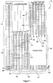
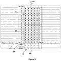
- FIG. 1 illustrates an elevator system deployment scheme 100 employing two independently moving elevator cars (Twin Cars) operating within each elevator shaft according to an aspect of the present invention.
- the system 100 represents a zoned twin elevator system.
- Each elevator car or lift operates within an elevator shaft, where each shaft is designated by a lift number 102 (e.g., 1-12).
- Elevator shafts 1-12, as indicated by 104 are illustrated at the bottom of deployment scheme 100, where a first group of elevator shafts, indicated by 106, provide transportation services to a first region of floors within a building (e.g., floors 1-20), as indicated by 108.
- a second group of elevator shafts, indicated by 110 similarly provide transportation services to a second region of floors with the building (e.g., floors 21-40), as indicated by 112.
- elevator shaft 114 comprises a twin elevator system incorporating two elevator cars that move independently of each other, where independent motion is enabled by providing separate counter weight, rope, and traction drive units for each elevator car.
- a first region 116 within shaft 114 denoted by lighter colored circles, indicate the floors (i.e., floors 1-10) that are serviced by a first elevator car (not shown) associated with the twin elevator cars.
- a second region 118 within shaft 114 denoted by the dark colored circles, indicate floors (i.e., floors 11-20) that are serviced by a second elevator car (not shown).
- Passengers or uses requiring transportation to floors in the first region 116 may enter the first elevator car on a lower ground level 120 of the building, whereas passengers or users traveling to the floors associated with the second region 118 may enter the second elevator car from the upper ground level 122.
- Access between the upper and lower ground levels may be provided, for example, by a connecting stair case, a shuttle elevator, and/or an escalator 124. All the other elevator shafts 126,128, 130, 132,134 within the first group of elevators 106 are identical to that of elevator shaft 114, described above.
- the number of elevator shafts designated for each elevator group, and the number of floors associated with each region are for purposes of illustration and not limitation, and may vary according to various elevator system design factors (e.g., building size, traffic, etc.). Also, it may be possible to increase the number of elevator cars operating within each shaft to more than two.
- One or more elevator system controllers may include various safety and monitoring procedures for ensuring that the independently moving elevator cars sharing a shaft do not come within a certain range or distance of each other for collision avoidance and safety purposes.
- elevator shaft 140 also comprises a twin elevator system incorporating two elevator cars that move independently of each other.
- a first region 142 within shaft 140 denoted by lighter colored circles, indicate the floors (i.e., floors 21-30) that are serviced by a first elevator car (not shown) associated with the twin elevator cars.
- a second region 144 within shaft 140 denoted by the dark colored circles, indicate floors (i.e., floors 31-40) that are serviced by a second elevator car (not shown).
- Passengers or users requiring transportation to floors in the first region 142 may enter the first elevator car on a lower ground level 120 of the building, whereas passengers or users traveling to floors associated with the second region 144 may enter the second elevator car from upper ground level 122.
- access between the upper and lower ground levels may be provided, for example, by a connecting stair case, a shuttle elevator, and/or an escalator 124.
- All the other elevator shafts 146, 148, 150, 152, 154 within the second group of elevators 110 are identical to that of elevator shaft 140, described above.
- the second group of elevator cars 110 comprise a express zone 158 over which the elevator cars do not stop until the upper region floors (i.e., floors 21-40) have been reached.
- the express zone facilitates an expedited service for passengers wishing to be transported to the upper floors of the building, while simultaneously providing the advantages of multiple elevator cars within each shaft.
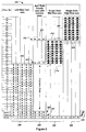
- FIG 2 illustrates an elevator system deployment scheme 200 employing two independently moving elevator cars (Twin Cars) operating within each elevator shaft according to another aspect of the present invention.
- the scheme 200 according to the present invention represents a hybrid elevator system comprising a twin elevator scheme 202 and a split twin shuttle scheme 204.
- Elevator scheme 202 is identical to that of region 106 shown in Figure 1 , where shafts 1-5, as indicated by 206, each include two elevator cars within each shaft for servicing floors 1-20.
- the split twin shuttle scheme 204 comprises a plurality of shafts 208 (i.e., shafts 6-8), where each shaft has two elevator cars that travel between a ground level and a lower and upper sky lobby 210, 212.
- a first elevator car (not shown) transports passengers between a lower ground floor level 222 and the lower sky lobby 210 (lighter colored circles). At the lower sky lobby 210, the passengers may access a bank of elevators 214 that service the mid-level floors of the building, as indicated by region 216. Similarly, a second elevator car (not shown) transports passengers between an upper ground floor level 224 and the upper sky lobby 212 (dark colored circles). At the upper sky lobby 212, the passengers may access another bank of elevators 218 that service the upper-level floors of the building, as indicated by region 220.
- elevator banks 214 and 218 are accessible from the upper level floors (i.e., floor 21 and 31, respectively).
- This provides an advantage where the shafts for these elevator banks 214, 218 do not have to extend down to the ground floor level as the elevator cars are operable from their respective sky lobbies.
- elevator shafts 9-12, indicated by 226, are not required to extend from floor 21 to the lower ground level 222.
- elevator shafts 13-16, indicated by 228, are not required to extend from floor 31 to the upper ground level 224. This provides an increase in building core space, in addition to providing more efficient elevator traffic management.
- Passengers requiring transportation to lower sky lobby 210 may enter the first elevator car on the lower ground level 222 of the building, whereas passengers traveling to upper sky lobby 212 may enter the second elevator car from the upper ground level 224.
- Access between the upper and lower ground levels 222, 224 may be provided, for example, by a connecting stair case, a shuttle elevator, and/or an escalator 230.
- elevator cars associated with elevator shafts 1-5, as indicated by 206 may be accessed from the lower or upper ground levels 222, 224 depending on whether passengers require transportation to the lower level floors, denoted by the lighter colored circles, or the upper floors, as indicated by the dark colored circles.
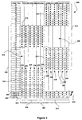
- FIG. 3 illustrates an elevator system deployment scheme 300 comprising two independently moving elevator cars (Twin Cars) operating within each elevator shaft according to an aspect of the present invention.
- the system 300 according to the present invention represents a zoned twin elevator system, where each zone has a respective express region therebetween.
- Each elevator car operates within an elevator shaft, where each shaft is designated by a lift or elevator number 302 (e.g., 1-12).
- Elevator shafts 1-12, as indicated by 304, are illustrated at the bottom of deployment scheme 300, where a first group of elevator shafts, indicated by 306, provide transportation services to a first region of floors within a building (e.g., floors 1-30), as indicated by 308.
- a second group of elevator shafts, indicated by 310 similarly provide transportation services to a second region of floors with the building (e.g., floors 11-40), as indicated by 312.
- elevator shaft 314 comprises a twin elevator system incorporating two elevator cars that move independently of each other within the shaft. Independent motion is enabled by providing separate counter weight, rope, and traction drive units for each elevator car. Other known methods known in the art of elevator motion and control may be incorporated to achieve independent movement of the elevator cars.
- an express region 319 is located between regions 316 and 318, which expedites the transportation of passengers to the upper floors of the elevator cars operating within the first group of elevator shafts indicated by 306.
- the express region 319 also simplifies the safety and control capabilities of the elevator control system. This is facilitated by the physical separation between any two elevator cars operating in their designated regions within each shaft. For example, there is a ten floor separation between the first elevator car operating within region 316 and the second elevator car operating within region 318. In such a scenario, the closest proximity between the cars operating in regions 316 and 318 is ten floors, which accounts for a relatively safe distance between the cars. If either car violates this distance, either or both elevator cars can be safely closed down using less complex sensor and control programming.
- Passengers requiring transportation to floors in the first region 316 may enter the first elevator car on a lower ground level 320 of the building, whereas passengers or users traveling to the floors associated with the second region 318 may enter the second elevator car from the upper ground level 322.
- Access between the upper and lower ground levels may be provided, for example, by a connecting stair case, a shuttle elevator, and/or an escalator 324. All the other elevator shafts 326, 328, 330, 332, 334 within the first group of elevators 306 are identical to that of elevator shaft 314, described above.
- the number of elevator shafts designated for each elevator group, and the number of floors associated with each region are for purposes of illustration and not limitation, and may vary according to various elevator system design factors (e.g., building size, traffic, etc.). Also, it may be possible to increase the number of elevator cars operating within each shaft to more than two.
- One or more elevator system controllers may include various safety and monitoring procedures for ensuring that the independently moving elevator cars sharing a shaft do not come within a certain range or distance of each other for collision avoidance and safety purposes.
- elevator shaft 340 also comprises a twin elevator system incorporating two elevator cars that move independently of each other.
- a first region 342 within shaft 340 denoted by lighter colored circles, indicate the floors (i.e., floors 21-30) that are serviced by a first elevator car (not shown) associated with the twin elevator cars.
- a second region 344 within shaft 340 denoted by the dark colored circles, indicate floors (i.e., floors 31-40) that are serviced by a second elevator car (not shown).
- an express region 356 is also located between regions 342 and 344, which expedites the transportation of passengers to the upper floors of the elevator cars operating within the first group of elevator shafts indicated by 310.
- the express region 356 also simplifies the safety and control capabilities of the elevator control system. This is facilitated by the physical separation between any two elevator cars operating in their designated regions within each shaft.
- Passengers or users requiring transportation to floors in the first region 342 may enter the first elevator car on a lower ground level 320 of the building, whereas passengers or users traveling to floors associated with the second region 344 may enter the second elevator car from upper ground level 322.
- access between the upper and lower ground levels may be provided, for example, by a connecting stair case, a shuttle elevator, and/or an escalator 324. All the other elevator shafts 346, 348, 350, 352, 354 within the second group of elevators 310 are identical to that of elevator shaft 340, described above.
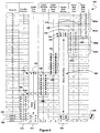
- FIG. 4 illustrates a yet another hybrid elevator system deployment scheme 400, which includes two independently moving elevator cars (Twin Cars) operating within each elevator shaft according to another aspect of the present invention.
- the scheme 400 according to the present invention represents a hybrid elevator system comprising a zoned twin elevator scheme 402, a split twin shuttle scheme 404, a double deck elevator shuttle 406, and an upper and lower zoned twin elevator scheme 408, 410.
- Elevator scheme 402 is identical to that of scheme 202 illustrated and described in connection with Figure 2 , where shafts 1-2, as indicated by 412, each include two elevator cars within each shaft for servicing floors 1-8.
- the split twin shuttle scheme 404 is identical to that of scheme 204 illustrated and described in connection with Figure 2 , and comprises a plurality of shafts 414 (i.e., shafts 3-4), where each shaft has two elevator cars that travel between a ground level and a lower mid-level and upper mid-level sky lobby 416, 418, respectively.
- a first elevator car (not shown) transports passengers between a lower ground floor level 422 and the lower mid-level sky lobby 416 (lighter colored circles) via an express zone 417.
- the passengers may access a bank of elevators 424 that service the lower mid-level floors of the building, as indicated by region 426.
- a second elevator car (not shown) transports passengers between an upper ground floor level 423 and the upper mid-level sky lobby 418 (dark colored circles) via express zone 417.
- the passengers may access another bank of elevators 430 that service the upper mid-level floors of the building, as indicated by region 432.
- elevator banks 426 and 430 are accessible from the mid level floors (i.e., floor 9 and 18, respectively).
- This provides an advantage, where the shafts corresponding to these elevator banks 426, 430 do not have to extend down to the ground floor level, as the elevator cars are operable from their respective sky lobbies (i.e., floor 9 and 18, respectively).
- elevator shafts 5-6, indicated by 426 are not required to extend from floor 9 to the lower ground level 422.
- elevator shafts 7-8, indicated by 430 are not required to extend from floor 17 to the upper ground level 423. This provides an increase in building core space, in addition to providing more efficient elevator traffic management.
- Passengers requiring transportation to lower mid-level sky lobby 416 may enter the first elevator car on the lower ground level 422 of the building, whereas passengers traveling to upper mid-level sky lobby 418 may enter the second elevator car from the upper ground level 423.
- Access between the upper and lower ground levels 422, 423 may be provided, for example, by a connecting stair case, a shuttle elevator, and/or an escalator 436.
- elevator cars associated with elevator shafts 1-2, as indicated by 412 may be accessed from the lower or upper ground levels 422, 423 depending on whether passengers require transportation to the lower level floors, denoted by the lighter colored circles, or the upper floors, as indicated by the dark colored circles.
- the double deck elevator shuttle scheme 406 illustrated in Figure 4 comprises a plurality of shafts (i.e., 9-10), as indicated by 440.
- Each shaft includes a double deck elevator car (not shown) which comprises a lower deck elevator car coupled to an upper deck elevator car.
- the double deck elevator car When the double deck elevator car is at any given floor, the upper deck elevator car concurrently serves the floor immediately above the floor served by the lower deck elevator car.
- the double deck elevator car associated with each of the plurality of shafts 440 provides passenger transportation between the upper and lower ground floor levels 422, 423, and a first and second upper-level lobby 442, 444, respectively.
- Zoned twin scheme 408 comprises a top down zoned twin system, whereby floor region 450B is serviced by a first elevator car operating within each shaft (i.e., Lift No. 11-12) and floor region 452B is, similarly, serviced by a second elevator car operating within each shaft (i.e., Lift No. 11-12).
- Zoned twin scheme 410 comprises floor region 450A, which is serviced by a first elevator car operating within each shaft (i.e., Lift No. 13-14) and floor region 452A is, similarly, serviced by a second elevator car operating within each shaft (i.e., Lift No. 11-12) of the zoned twin system.
- Passengers requiring access to floor regions 450B and 452A may access elevator banks 446 and 448 by taking one of the double deck elevator cars (i.e., Lift No. 9 or 10) from upper ground level 423 to the second upper-level lobby 444.
- floor regions 450A and 452B may be accessed via elevator banks 446 and 448 by taking one of the double deck elevator cars (i.e., Lift No. 9 or 10) from lower ground level 422 to the first upper-level lobby 442.
- the upper and lower zoned twin elevator schemes 408, 410 are accessed by the double deck elevator shuttle scheme 406 and, thus, provide an efficient means of traffic management, whereby passengers requiring service to the upper floors of the building are transported via express zone 456 to the upper-level lobbies 442, 444.
- This also enables the elevator shafts within elevator banks 446 and 448 to extend only as far down as the lowest floor for which they provide service.
- the elevator shafts associated with elevator bank 446 may only need to extend as far "floor 28," which facilitates the use of core building space below this floor (i.e., floor 28).
- the shafts of elevator bank 448 may only need to extend from the top region of the building to "floor 37." Hence, the use of core building space below "floor 37" is mad made available.
- the number of floors and elevator shafts (i.e., indicated by lift no.) illustrated in connection with Figure 4 are for purposes of illustration and not of limitation. For example, the number of floors and elevator shafts may be increased in accordance with traffic management, elevator system design principles, and/or other factors.
- FIG. 5 illustrates an elevator deployment scheme 500 for providing a combination of goods and passenger transportation according to an aspect of the present invention.
- transportation of both goods and passengers is provided by two independently moving elevator cars operating within each shaft, as indicated by 502.
- Each elevator shaft comprises a lower and an upper elevator car, where transportation provided by the lower elevator car is indicated by the lighter colored circles and service provided by upper car is identified by the dark colored circles.
- Transportation between the ground floor level and a floor immediately below the top floor (i.e., 15 th floor), as indicated by 504 is provided by both the upper and lower elevator cars moving within each shaft.
- Transportation to the basement 506 is provided by the lower elevator car only.
- transportation to the top floor 508 i.e., 16 th floor
- the upper elevator may move into the virtual landing area 510, allowing the lower elevator car to service or provide transportation to the top floor 508.
- the virtual landing may comprise a location in the hoistway or elevator shaft, where one of the twin elevator cars can be moved in order to make way for the other elevator car operating within the same elevator shaft.
- the lighter colored circles designate the floors that receive transportation services from the lower elevator cars within each of elevator shafts 1-6, defined by 502.
- the lower elevator cars may be used as a goods or services elevator.
- the darker colored circles designate the floors that receive transportation services from the upper elevator cars within each of elevator shafts 1-6, defined by 502, whereby the upper elevator cars may provide passenger transportation.
- the minimum permissible safe distance between the upper and lower elevator cars may be a single floor.
- the lower elevator car may be on the 5 th floor and the upper elevator car may be directly above it on the 6 th floor.
- the control mechanisms for controlling and maintaining a safe distance between the upper and lower elevator cars may depend on the elevator controller system (not shown) and sensory technology (not shown) employed. For example, based on safety and other considerations, a minimum safe distance of two or more floors may be required between the elevator cars.
- the elevator controller may also provide a priority based elevator dispatching process, that assigns a higher priority to passenger transportation relative to goods or services transportation. Therefore, the controller system may ensure that the elevator shafts are mainly free and not obstructed by the lower goods elevator cars during periods when passenger traffic is high (e.g., 5pm in an office building).
- FIG. 6 illustrates an elevator deployment scheme 600 comprising a zoned twin elevator system according to an aspect of the present invention.
- the zoned twin elevator is identical to the zoned twin system described and illustrated in connection with Figure 1 , accept that deployment scheme 600 comprises a single ground floor level 602 (i.e., no upper and lower ground floor level) and a virtual landing 604 that is located beneath ground level 602.
- Each of the elevator shafts, indicated by 606, include two elevator cars (not shown) independent operating within them.
- each elevator operates within a region or zone.
- a first elevator car provides transportation between the ground floor 602 and the 10 th floor of the building, as indicated by region 608, and designated by the lighter colored circles.
- a second elevator car provides transportation from the ground floor 602 to the upper floors of the building (i.e., floors 11-20), as indicated by region 610, and designated by the darker colored circles.
- both the first and second elevator cars may load passengers from the ground level 602.
- the first elevator cars operating in region 608 may load passengers from their rear doors and the second elevator cars operating in region 610 load passengers from their front doors.
- only one of the elevator cars operating within each shaft can access the ground floor 602 for the purpose of loading passengers. If, for example, the second elevator car operating in region 610 is assigned to load passengers from the ground floor 602, the first elevator car operating in region 608 must be relocated to the virtual landing 604 in order to allow the second elevator to access the ground floor 602.
- the second elevator car should be operating within region 610 or be located at a minimum safe distance above the first elevator car in compliance with the safety standards and mechanisms in place.
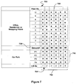
- FIG. 7 illustrates an elevator deployment scheme 700 comprising a zoned twin elevator system according to an aspect of the present invention.
- Each of the elevator shafts, indicated by 702 include two elevator cars (not shown) independent operating within them.
- each elevator operates within a region or zone.
- a first elevator car provides transportation between the ground floor 706 and the top floor of the building, as indicated by region 708, and designated by the dark colored circles.
- a second elevator car provides transportation from the ground floor 706 to the sub-ground level floors of the building (i.e., floors P1-P4), as indicated by region 710, and designated by the lighter colored circles.
- the sub-ground level floors, indicated by 710 may, for example, be parking levels underneath the building.
- the floor levels located above ground level 706, may for example, be residential apartments, offices, and/or commercial shopping floors.
- elevator deployment scheme 700 comprises a single ground floor level 706 (i.e., no upper and lower ground floor level). Both the first and second elevator cars within each shaft may load passengers from the ground level 706. The first elevator cars operating in region 708 may load passengers from their front doors and the second elevator cars operating in region 710 (i.e., parking levels) may load passengers from their rear doors. At any given instant, only one of the elevator cars operating within each shaft can access the ground floor 706 for the purpose of loading passengers.
- the first elevator car operating in region 708 should remain operating at a minimum safe distance from the second elevator car in region 708.
- the second elevator car should be operating within region 710 and be located at a minimum safe distance below the first elevator car.
- This deployment scheme 700 increases the traffic flow significantly by allowing each of the twin elevator cars to operate in two separate regions 708, 710 that have little or no overlap within each shaft (e.g., shaft 702).
Claims (15)
- Ein Aufzugsystem (100, 200, 300, 400, 500, 600, 700) eines Gebäudes, umfassend:einen ersten Bereich (116);einen zweiten Bereich (118), wobei der zweite Bereich wenigstens teilweise über dem ersten Bereich angeordnet ist;eine erste Aufzugkabine zum Bewegen innerhalb des ersten Bereichs;eine zweite Aufzugkabine zum Bewegen innerhalb des zweiten Bereichs, wobei die ersten und zweiten Aufzugkabinen innerhalb eines ersten Aufzugschachts (106, 206, 306, 412, 502, 602, 702) angeordnet sind und unabhängig voneinander beweglich gesteuert werden; undwenigstens einen Transfervorraum, in welchem Passagiere die erste Aufzugkabine und die zweite Aufzugkabine betreten können.
- Aufzugsystem (100, 200, 300, 400, 500, 600, 700) gemäß Anspruch 1, wobei der erste Bereich (116) und der zweite Bereich (118) sich nicht überlappen.
- Aufzugsystem (100, 200, 300, 400, 500, 600, 700) gemäß Anspruch 1, wobei der erste Bereich (116) und der zweite Bereich (118) sich wenigstens teilweise überlappen.
- Aufzugsystem (100, 200, 300, 400, 500, 600, 700) gemäß Anspruch 1, des Weiteren umfassend:einen dritten Bereich, der über dem zweiten Bereich (118) angeordnet ist;eine dritte Aufzugkabine zum Bewegen innerhalb des dritten Bereichs, wobei die dritte Aufzugkabine innerhalb des ersten Aufzugschachts (106, 206, 306, 412, 502, 606, 702) angeordnet ist, und unabhängig von den ersten und zweiten Aufzugkabinen beweglich gesteuert wird.
- Aufzugsystem (100, 200, 300, 400, 500, 600, 700) gemäß Anspruch 1, des Weiteren umfassend:einen zweiten Aufzugschacht; undeinen Expressaufzugzubringer, der sich im zweiten Aufzugschacht bewegt.
- Aufzugsystem (100, 200, 300, 400, 500, 600, 700) gemäß Anspruch 5, wobei der Expressaufzugzubringer exklusiv den wenigstens einen Transfervorraum von einem Erdgeschosstransfervorraum aus bedient.
- Aufzugsystem (100, 200, 300, 400, 500, 600, 700) gemäß Anspruch 6, wobei der Expresszubringer eine Auswahl aus einer einzelnen Expressaufzugkabine, zweier Expressaufzugkabinen und einer Doppeldeckeraufzugkabine umfasst.
- Aufzugsystem (100, 200, 300, 400, 500, 600, 700) gemäß Anspruch 5, wobei der Expresszubringer eine Auswahl aus einer einzelnen Expressaufzugkabine, zweier Expressaufzugkabinen und einer Doppeldeckeraufzugkabine umfasst.
- Aufzugsystem (100, 200, 300, 400, 500, 600, 700) gemäß Anspruch 1, wobei der wenigstens eine Transfervorraum eine obere Transferebene und eine untere Transferebene, die durch eine Auswahl aus einer Treppe, einem Zubringeraufzug und einer Rolltreppe miteinander verbunden sind, umfasst.
- Verfahren zum Betreiben eines Aufzugsystems (100, 200, 300, 400, 500, 600, 700) umfassend eine erste und eine zweite unabhängig betreibbare Aufzugkabine innerhalb von jedem des wenigstens einen Aufzugschachts (106, 206, 306, 412, 502, 606, 702) innerhalb eines Gebäudes, wobei das Verfahren umfasst:Bereitstellen von Passagiertransport in einem ersten Bereich (116) unter Verwendung der ersten Aufzugskabine in dem wenigstens einen Aufzugschacht, wobei der erste Bereich durch eine Vielzahl von Ebenen des Gebäudes definiert wird, wobei sich der erste Bereich zwischen einer ersten Ebene und einer zweiten Ebene erstreckt und diese einschließt;Bereitstellen von Passagiertransport in einen zweiten Bereich (118) unter Verwendung der zweiten Aufzugkabine in dem wenigstens einen Aufzugschacht, wobei der zweite Bereich durch eine Vielzahl von Ebenen des Gebäudes definiert wird, wobei sich der zweite Bereich zwischen einer dritten Ebene und einer vierten Ebene erstreckt und diese einschließt; dadurch gekennzeichnet, dass es weiterhin umfasstSteuern der Beladung der ersten Aufzugkabine von der ersten Ebene aus durch das Bewegen der zweiten Aufzugkabine in einen virtuellen Landebereich, wobei sich der virtuelle Landebereich außerhalb des ersten und des zweiten Bereichs befindet.
- Verfahren nach Anspruch 10, wobei die erste Ebene eine Grundebene des ersten Bereichs ist.
- Verfahren nach Anspruch 10, wobei die erste Ebene eine oberste Ebene des ersten Bereichs ist.
- Verfahren nach Anspruch 10, wobei die dritte Ebene und die erste Ebene die gleiche Ebene sind.
- Verfahren nach Anspruch 13, wobei die vierte Ebene und die zweite Ebene die gleiche Ebene sind.
- Verfahren nach Anspruch 10, wobei die dritte Ebene außerhalb des ersten Bereichs liegt.
Applications Claiming Priority (2)
| Application Number | Priority Date | Filing Date | Title |
|---|---|---|---|
| US11/207,539 US7841450B2 (en) | 2005-08-19 | 2005-08-19 | Twin elevator systems |
| EP06801074.3A EP1915308B1 (de) | 2005-08-19 | 2006-08-09 | Doppelaufzugsysteme |
Related Parent Applications (2)
| Application Number | Title | Priority Date | Filing Date |
|---|---|---|---|
| EP06801074.3A Division EP1915308B1 (de) | 2005-08-19 | 2006-08-09 | Doppelaufzugsysteme |
| EP06801074.3A Division-Into EP1915308B1 (de) | 2005-08-19 | 2006-08-09 | Doppelaufzugsysteme |
Publications (2)
| Publication Number | Publication Date |
|---|---|
| EP2860140A1 EP2860140A1 (de) | 2015-04-15 |
| EP2860140B1 true EP2860140B1 (de) | 2016-03-30 |
Family
ID=37766437
Family Applications (2)
| Application Number | Title | Priority Date | Filing Date |
|---|---|---|---|
| EP06801074.3A Not-in-force EP1915308B1 (de) | 2005-08-19 | 2006-08-09 | Doppelaufzugsysteme |
| EP14003906.6A Not-in-force EP2860140B1 (de) | 2005-08-19 | 2006-08-09 | Aufgeteiltes Aufzugssystem |
Family Applications Before (1)
| Application Number | Title | Priority Date | Filing Date |
|---|---|---|---|
| EP06801074.3A Not-in-force EP1915308B1 (de) | 2005-08-19 | 2006-08-09 | Doppelaufzugsysteme |
Country Status (8)
| Country | Link |
|---|---|
| US (5) | US7841450B2 (de) |
| EP (2) | EP1915308B1 (de) |
| JP (1) | JP2009504540A (de) |
| AU (1) | AU2006283763A1 (de) |
| BR (1) | BRPI0615359A2 (de) |
| CA (3) | CA2619764C (de) |
| ES (1) | ES2535711T3 (de) |
| WO (1) | WO2007024488A2 (de) |
Families Citing this family (42)
| Publication number | Priority date | Publication date | Assignee | Title |
|---|---|---|---|---|
| SG111198A1 (en) * | 2003-10-09 | 2005-05-30 | Inventio Ag | Lift installation for zonal operation in a building, method for zonal operation of such a lift installation and method for modernisation of a lift installation |
| EP1765710A4 (de) * | 2004-06-21 | 2011-09-21 | Otis Elevator Co | Aufzugssytem mit mehreren kabinen in einem schacht |
| EP1666398B1 (de) * | 2004-12-01 | 2013-06-19 | Inventio AG | Verfahren zur Beförderung von Personen in einem Gebäude |
| EP1666399B1 (de) * | 2004-12-01 | 2012-10-31 | Inventio AG | Verfahren zur Beförderung von Personen in einem Gebäude |
| WO2006065241A2 (en) * | 2004-12-16 | 2006-06-22 | Otis Elevator Company | Elevator system with multiple cars in a hoistway |
| WO2006071222A1 (en) * | 2004-12-29 | 2006-07-06 | Otis Elevator Company | Compensation in an elevator system having multiple cars within a single hoistway |
| KR100946353B1 (ko) * | 2005-02-04 | 2010-03-08 | 오티스 엘리베이터 컴파니 | 승강로 내의 2 대의 카 중 어느 한 쪽에 부과되는 지연을최소화시키기 위하여 상기 2 대의 카 중 하나의 카에할당되는 호출들 |
| EP1853506B1 (de) * | 2005-02-04 | 2011-11-02 | Otis Elevator Company | Ankündigungen, die anzeigen, dass ein wagen auf einen anderen wagen im gleichen schacht wartet |
| CN100554120C (zh) * | 2005-02-17 | 2009-10-28 | 奥蒂斯电梯公司 | 将轿厢去往底坑或者顶部的运行告知电梯乘客的方法 |
| CN101119916B (zh) * | 2005-02-17 | 2010-09-29 | 奥蒂斯电梯公司 | 在具有两个轿厢的电梯通道内防止碰撞的方法 |
| DE112005003475B4 (de) * | 2005-02-25 | 2019-04-18 | Otis Elevator Co. | Aufzugfahrkorb mit einer abgewinkelten Unterzugs-Verseilungsanordnung |
| US7841450B2 (en) * | 2005-08-19 | 2010-11-30 | Thyssenkrupp Elevator Capital Corporation | Twin elevator systems |
| EP2032489B1 (de) * | 2006-06-07 | 2018-12-05 | Otis Elevator Company | Mehrkabinenaufzugsschachttrenngewährleistung |
| IL184194A (en) * | 2006-07-25 | 2012-02-29 | Inventio Ag | Method of modernizing a lift installation |
| WO2008079147A1 (en) * | 2006-12-22 | 2008-07-03 | Otis Elevator Company | Elevator system with multiple cars in a single hoistway |
| EP1970342A1 (de) * | 2007-03-15 | 2008-09-17 | Inventio Ag | Anzeigevorrichtung und Kommunikationsverfahren für ein Aufzugsystem |
| KR100898916B1 (ko) * | 2007-04-02 | 2009-05-26 | 최성식 | 엘리베이터 시스템 및 그 제어방법 |
| WO2009024853A1 (en) * | 2007-08-21 | 2009-02-26 | De Groot Pieter J | Intelligent destination elevator control system |
| FI119686B (fi) * | 2007-10-11 | 2009-02-13 | Kone Corp | Hissijärjestelmä |
| US8297409B2 (en) * | 2007-11-30 | 2012-10-30 | Otis Elevator Company | Coordination of multiple elevator cars in a hoistway |
| WO2009073025A1 (en) * | 2007-12-05 | 2009-06-11 | Otis Elevator Company | Control strategy for operating two elevator cars in a single hoistway |
| BRPI0822608B1 (pt) | 2008-04-28 | 2020-03-03 | Inventio Ag | Sistema de elevadores, processo para o reequipamento de um sistema de elevadores e porta de prédio |
| FI20080640L (fi) * | 2008-11-28 | 2010-05-29 | Kone Corp | Hissijärjestelmä |
| JP5771431B2 (ja) * | 2011-04-12 | 2015-08-26 | 株式会社日立製作所 | 複数バンクの群管理エレベーター |
| CN103764533B (zh) | 2011-09-08 | 2017-05-31 | 奥的斯电梯公司 | 具有动态运输分布解决方案的升降机系统 |
| CN102616630A (zh) * | 2012-04-09 | 2012-08-01 | 李凯 | 单向电梯及其运行方法 |
| EP2864230B1 (de) * | 2012-06-25 | 2016-06-22 | Inventio AG | Transfers in aufzugsystemen mit mehreren decks |
| US10059566B2 (en) * | 2013-05-07 | 2018-08-28 | Otis Elevator Company | Connecting cars in a multicar elevator system |
| JP6143599B2 (ja) * | 2013-08-02 | 2017-06-07 | 三菱電機株式会社 | エレベータの運転装置、及びエレベータの運転方法 |
| ES2536799B1 (es) * | 2013-11-28 | 2016-03-04 | Fernando Antolín García | Sistema optimizado de transporte en ascensor en edificios de gran altura |
| CN105939948B (zh) * | 2013-12-05 | 2019-11-05 | 奥的斯电梯公司 | 电梯组中的目的地分配和可变能力 |
| US9440818B2 (en) * | 2014-01-17 | 2016-09-13 | Thyssenkrupp Elevator Corporation | Elevator swing operation system and method |
| DE102014220966A1 (de) | 2014-10-16 | 2016-04-21 | Thyssenkrupp Elevator Ag | Verfahren zum Betreiben einer Transportanlage sowie entsprechende Transportanlage |
| CN106794957A (zh) * | 2014-10-23 | 2017-05-31 | 三菱电机株式会社 | 电梯系统 |
| US9896303B2 (en) | 2014-12-10 | 2018-02-20 | Thyssenkrupp Elevator Corporation | Method for controlling elevator cars |
| DE102015102563A1 (de) * | 2015-02-23 | 2016-08-25 | Thyssenkrupp Ag | Verfahren zum Betreiben eines Aufzugsystems mit mehreren Schächten und mehreren Kabinen |
| AU2016231585B2 (en) | 2015-09-25 | 2018-08-09 | Otis Elevator Company | Elevator component separation assurance system and method of operation |
| US9650226B2 (en) * | 2015-09-28 | 2017-05-16 | Smart Lifts, Llc | System and method for controlling multiple elevator cabs in an elevator shaft |
| US10611568B2 (en) | 2017-01-25 | 2020-04-07 | Intelligrated Headquarters, Llc | AS/RS lift having vertically-aligned dual carriages |
| EP3357850A1 (de) | 2017-02-07 | 2018-08-08 | KONE Corporation | Aufzugsmontage im shuttle-modus |
| US11027943B2 (en) * | 2018-03-29 | 2021-06-08 | Otis Elevator Company | Destination dispatch sectoring |
| US11292690B2 (en) | 2018-07-25 | 2022-04-05 | Otis Elevator Company | Capacity shifting between partially-overlapping elevator groups |
Family Cites Families (36)
| Publication number | Priority date | Publication date | Assignee | Title |
|---|---|---|---|---|
| US1911834A (en) | 1931-02-26 | 1933-05-30 | Otis Elevator Co | Elevator system |
| US1837643A (en) | 1931-03-28 | 1931-12-22 | Otis Elevator Co | Elevator system |
| JPS5856475B2 (ja) * | 1979-08-03 | 1983-12-15 | 株式会社東芝 | 誘導加熱調理器の発振回路 |
| JPS59207379A (ja) * | 1983-05-12 | 1984-11-24 | 大成建設株式会社 | 建築構造物 |
| FI85970C (fi) * | 1986-09-24 | 1992-06-25 | Kone Oy | Foerfarande foer koordinering av hissgrupper. |
| JP2776940B2 (ja) * | 1990-02-13 | 1998-07-16 | 株式会社日立製作所 | エレベータ装置 |
| US5419414A (en) * | 1993-11-18 | 1995-05-30 | Sakita; Masami | Elevator system with multiple cars in the same hoistway |
| JPH07187525A (ja) * | 1993-11-18 | 1995-07-25 | Masami Sakita | 複数ばこエレベータシステム |
| GB2324170A (en) | 1995-03-31 | 1998-10-14 | Masami Sakita | Elevator dispatch system |
| DE59611367D1 (de) * | 1995-10-17 | 2006-08-31 | Inventio Ag | Sicherheitseinrichtung für eine Aufzugsgruppe |
| US5773772A (en) * | 1996-06-19 | 1998-06-30 | Otis Elevator Company | Transferring elevator cabs between non-contiguous hoistways |
| US5823299A (en) * | 1996-06-19 | 1998-10-20 | Otis Elevator Company | Shuttle elevators feeding local elevators |
| US5924524A (en) * | 1996-07-25 | 1999-07-20 | Otis Elevator Company | Integrated, multi-level elevator shuttle |
| US5752585A (en) * | 1996-07-25 | 1998-05-19 | Otis Elevator Company | Elevator shuttle with auxiliary elevators at terminals |
| US5861587A (en) * | 1997-11-26 | 1999-01-19 | Otis Elevator Company | Method for operating a double deck elevator car |
| FI112063B (fi) * | 2000-07-14 | 2003-10-31 | Kone Corp | Menetelmä liikenteen kontrolloimiseksi vaihtotasolla |
| JP4642200B2 (ja) * | 2000-09-07 | 2011-03-02 | 三菱電機株式会社 | エレベーター群管理制御装置 |
| EP1302431B1 (de) | 2001-10-15 | 2005-10-05 | ThyssenKrupp Elevator AG | Seilaufzugsystem mit zwei Fahrkörben mit gemeinsamen und getrennten Farhbahnabschnitten |
| FI112350B (fi) * | 2001-10-29 | 2003-11-28 | Kone Corp | Hissijärjestelmä |
| JP4131456B2 (ja) * | 2001-11-26 | 2008-08-13 | 三菱電機株式会社 | エレベーター群管理制御装置 |
| CN1299964C (zh) * | 2002-05-30 | 2007-02-14 | 三菱电机株式会社 | 电梯群管理控制装置 |
| FI113259B (fi) | 2002-06-03 | 2004-03-31 | Kone Corp | Menetelmä hissiryhmän hissien ohjaamiseksi |
| SG108324A1 (en) * | 2002-11-06 | 2005-01-28 | Inventio Ag | Control device and control method for a lift installation with multiple cage |
| JP4386842B2 (ja) * | 2002-11-26 | 2009-12-16 | ティッセンクルップ エレバートル アーゲー | エレベータ設備の制御方法、及び該方法を実行するためのエレベータ設備 |
| SG119203A1 (en) | 2002-12-13 | 2006-02-28 | Inventio Ag | Method and device for controlling a zonally operated elevator installation |
| US7198136B2 (en) * | 2003-09-11 | 2007-04-03 | Otis Elevator Company | Elevator device for a multi-sky-lobby system |
| SG111198A1 (en) * | 2003-10-09 | 2005-05-30 | Inventio Ag | Lift installation for zonal operation in a building, method for zonal operation of such a lift installation and method for modernisation of a lift installation |
| EP1526103B1 (de) * | 2003-10-09 | 2012-01-11 | Inventio AG | Aufzugsanlage mit mehrstöckigen Kabinen für den Zonenbetrieb in einem Gebäude |
| JP2005170597A (ja) * | 2003-12-11 | 2005-06-30 | Mitsubishi Electric Corp | エレベータ制御装置及び制御方法 |
| EP1765710A4 (de) * | 2004-06-21 | 2011-09-21 | Otis Elevator Co | Aufzugssytem mit mehreren kabinen in einem schacht |
| EP1783083B1 (de) * | 2004-08-26 | 2013-08-14 | Mitsubishi Denki Kabushiki Kaisha | Aufzugsgruppenmanagement-steuerung |
| CN100554120C (zh) * | 2005-02-17 | 2009-10-28 | 奥蒂斯电梯公司 | 将轿厢去往底坑或者顶部的运行告知电梯乘客的方法 |
| US7841450B2 (en) * | 2005-08-19 | 2010-11-30 | Thyssenkrupp Elevator Capital Corporation | Twin elevator systems |
| FI20080640L (fi) * | 2008-11-28 | 2010-05-29 | Kone Corp | Hissijärjestelmä |
| US9365392B2 (en) * | 2011-01-19 | 2016-06-14 | Smart Lifts, Llc | System having multiple cabs in an elevator shaft and control method thereof |
| FI124330B (fi) * | 2012-01-02 | 2014-06-30 | Kone Corp | Hissijärjestely ja menetelmä hissijärjestelyn uudelleenasettelemiseksi |
-
2005
- 2005-08-19 US US11/207,539 patent/US7841450B2/en not_active Expired - Fee Related
-
2006
- 2006-08-09 CA CA2619764A patent/CA2619764C/en not_active Expired - Fee Related
- 2006-08-09 WO PCT/US2006/031093 patent/WO2007024488A2/en active Application Filing
- 2006-08-09 JP JP2008527003A patent/JP2009504540A/ja active Pending
- 2006-08-09 AU AU2006283763A patent/AU2006283763A1/en not_active Abandoned
- 2006-08-09 CA CA2751650A patent/CA2751650C/en not_active Expired - Fee Related
- 2006-08-09 EP EP06801074.3A patent/EP1915308B1/de not_active Not-in-force
- 2006-08-09 EP EP14003906.6A patent/EP2860140B1/de not_active Not-in-force
- 2006-08-09 ES ES06801074.3T patent/ES2535711T3/es active Active
- 2006-08-09 BR BRPI0615359-3A patent/BRPI0615359A2/pt not_active Application Discontinuation
- 2006-08-09 CA CA2751637A patent/CA2751637C/en not_active Expired - Fee Related
-
2010
- 2010-11-30 US US12/957,128 patent/US8100230B2/en not_active Expired - Fee Related
-
2011
- 2011-12-21 US US13/332,540 patent/US8397873B2/en not_active Expired - Fee Related
-
2013
- 2013-03-12 US US13/796,021 patent/US8733507B2/en not_active Expired - Fee Related
-
2014
- 2014-04-07 US US14/246,502 patent/US20140216855A1/en not_active Abandoned
Also Published As
| Publication number | Publication date |
|---|---|
| EP1915308A2 (de) | 2008-04-30 |
| ES2535711T3 (es) | 2015-05-14 |
| US8397873B2 (en) | 2013-03-19 |
| JP2009504540A (ja) | 2009-02-05 |
| US20110073415A1 (en) | 2011-03-31 |
| WO2007024488A2 (en) | 2007-03-01 |
| EP1915308A4 (de) | 2012-09-19 |
| EP1915308B1 (de) | 2015-01-28 |
| US8100230B2 (en) | 2012-01-24 |
| US20140216855A1 (en) | 2014-08-07 |
| CA2751650C (en) | 2016-11-01 |
| AU2006283763A1 (en) | 2007-03-01 |
| EP2860140A1 (de) | 2015-04-15 |
| CA2751650A1 (en) | 2007-03-01 |
| CA2619764C (en) | 2011-10-18 |
| CA2619764A1 (en) | 2007-03-01 |
| CA2751637A1 (en) | 2007-03-01 |
| BRPI0615359A2 (pt) | 2011-05-17 |
| US20130186712A1 (en) | 2013-07-25 |
| US8733507B2 (en) | 2014-05-27 |
| CA2751637C (en) | 2013-11-12 |
| WO2007024488A3 (en) | 2007-05-10 |
| US20070039785A1 (en) | 2007-02-22 |
| US20120118674A1 (en) | 2012-05-17 |
| US7841450B2 (en) | 2010-11-30 |
Similar Documents
| Publication | Publication Date | Title |
|---|---|---|
| EP2860140B1 (de) | Aufgeteiltes Aufzugssystem | |
| US7917341B2 (en) | Elevator system including multiple cars in a hoistway destination entry control and parking positions | |
| CN107074482B (zh) | 用于操作运输系统的方法和相应的运输系统 | |
| EP2238064B1 (de) | Koordination von mehreren aufzugskabinen in einem schacht | |
| US7537089B2 (en) | Elevator installation with individually movable elevator cars and method for operating such an elevator installation | |
| US9365392B2 (en) | System having multiple cabs in an elevator shaft and control method thereof | |
| US7392883B2 (en) | Elevator group control system | |
| EP2349901A1 (de) | Aufzugssystem | |
| US9522807B2 (en) | System of elevator cabs and counterweights that move independently in different sections of a hoistway | |
| CN112888647A (zh) | 具有第一部分电梯系统和第二部分电梯系统的电梯系统 | |
| JP3135760B2 (ja) | エレベータシステム | |
| JPH0539173A (ja) | 自走エレベータの運行制御方法 | |
| JPH07277615A (ja) | 昇降機システム | |
| WO2007133173A2 (en) | Elevator system including car-to-car passenger transfer | |
| JPH07277609A (ja) | 昇降機システムの制御装置 | |
| CN110775745B (zh) | 多轿厢电梯以及多轿厢电梯控制方法 | |
| WO2014194330A2 (en) | System having multiple cabs in an elevator shaft and control method thereof | |
| JPH10129956A (ja) | エレベータシャトルシステムおよびエレベータかご室の輸送方法 |
Legal Events
| Date | Code | Title | Description |
|---|---|---|---|
| PUAI | Public reference made under article 153(3) epc to a published international application that has entered the european phase |
Free format text: ORIGINAL CODE: 0009012 |
|
| 17P | Request for examination filed |
Effective date: 20141120 |
|
| AC | Divisional application: reference to earlier application |
Ref document number: 1915308 Country of ref document: EP Kind code of ref document: P |
|
| AK | Designated contracting states |
Kind code of ref document: A1 Designated state(s): AT BE BG CH CY CZ DE DK EE ES FI FR GB GR HU IE IS IT LI LT LU LV MC NL PL PT RO SE SI SK TR |
|
| GRAP | Despatch of communication of intention to grant a patent |
Free format text: ORIGINAL CODE: EPIDOSNIGR1 |
|
| INTG | Intention to grant announced |
Effective date: 20151111 |
|
| RIN1 | Information on inventor provided before grant (corrected) |
Inventor name: THUM, GERHARD Inventor name: SMITH, RORY S. Inventor name: PETERS, RICHARD D. Inventor name: HUFF, RANDOLPH W. Inventor name: POWELL, BRUCE |
|
| GRAS | Grant fee paid |
Free format text: ORIGINAL CODE: EPIDOSNIGR3 |
|
| GRAA | (expected) grant |
Free format text: ORIGINAL CODE: 0009210 |
|
| AC | Divisional application: reference to earlier application |
Ref document number: 1915308 Country of ref document: EP Kind code of ref document: P |
|
| AK | Designated contracting states |
Kind code of ref document: B1 Designated state(s): AT BE BG CH CY CZ DE DK EE ES FI FR GB GR HU IE IS IT LI LT LU LV MC NL PL PT RO SE SI SK TR |
|
| REG | Reference to a national code |
Ref country code: GB Ref legal event code: FG4D |
|
| REG | Reference to a national code |
Ref country code: CH Ref legal event code: EP |
|
| REG | Reference to a national code |
Ref country code: AT Ref legal event code: REF Ref document number: 785146 Country of ref document: AT Kind code of ref document: T Effective date: 20160415 |
|
| REG | Reference to a national code |
Ref country code: IE Ref legal event code: FG4D |
|
| REG | Reference to a national code |
Ref country code: DE Ref legal event code: R096 Ref document number: 602006048512 Country of ref document: DE |
|
| REG | Reference to a national code |
Ref country code: CH Ref legal event code: NV Representative=s name: FIAMMENGHI-FIAMMENGHI, CH |
|
| RAP2 | Party data changed (patent owner data changed or rights of a patent transferred) |
Owner name: THYSSENKRUPP ELEVATOR CORPORATION |
|
| REG | Reference to a national code |
Ref country code: LT Ref legal event code: MG4D |
|
| PG25 | Lapsed in a contracting state [announced via postgrant information from national office to epo] |
Ref country code: GR Free format text: LAPSE BECAUSE OF FAILURE TO SUBMIT A TRANSLATION OF THE DESCRIPTION OR TO PAY THE FEE WITHIN THE PRESCRIBED TIME-LIMIT Effective date: 20160701 |
|
| REG | Reference to a national code |
Ref country code: NL Ref legal event code: MP Effective date: 20160330 |
|
| REG | Reference to a national code |
Ref country code: AT Ref legal event code: MK05 Ref document number: 785146 Country of ref document: AT Kind code of ref document: T Effective date: 20160330 |
|
| PG25 | Lapsed in a contracting state [announced via postgrant information from national office to epo] |
Ref country code: LT Free format text: LAPSE BECAUSE OF FAILURE TO SUBMIT A TRANSLATION OF THE DESCRIPTION OR TO PAY THE FEE WITHIN THE PRESCRIBED TIME-LIMIT Effective date: 20160330 Ref country code: SE Free format text: LAPSE BECAUSE OF FAILURE TO SUBMIT A TRANSLATION OF THE DESCRIPTION OR TO PAY THE FEE WITHIN THE PRESCRIBED TIME-LIMIT Effective date: 20160330 Ref country code: LV Free format text: LAPSE BECAUSE OF FAILURE TO SUBMIT A TRANSLATION OF THE DESCRIPTION OR TO PAY THE FEE WITHIN THE PRESCRIBED TIME-LIMIT Effective date: 20160330 |
|
| PG25 | Lapsed in a contracting state [announced via postgrant information from national office to epo] |
Ref country code: NL Free format text: LAPSE BECAUSE OF FAILURE TO SUBMIT A TRANSLATION OF THE DESCRIPTION OR TO PAY THE FEE WITHIN THE PRESCRIBED TIME-LIMIT Effective date: 20160330 |
|
| PG25 | Lapsed in a contracting state [announced via postgrant information from national office to epo] |
Ref country code: PL Free format text: LAPSE BECAUSE OF FAILURE TO SUBMIT A TRANSLATION OF THE DESCRIPTION OR TO PAY THE FEE WITHIN THE PRESCRIBED TIME-LIMIT Effective date: 20160330 Ref country code: IS Free format text: LAPSE BECAUSE OF FAILURE TO SUBMIT A TRANSLATION OF THE DESCRIPTION OR TO PAY THE FEE WITHIN THE PRESCRIBED TIME-LIMIT Effective date: 20160730 Ref country code: EE Free format text: LAPSE BECAUSE OF FAILURE TO SUBMIT A TRANSLATION OF THE DESCRIPTION OR TO PAY THE FEE WITHIN THE PRESCRIBED TIME-LIMIT Effective date: 20160330 |
|
| PG25 | Lapsed in a contracting state [announced via postgrant information from national office to epo] |
Ref country code: CZ Free format text: LAPSE BECAUSE OF FAILURE TO SUBMIT A TRANSLATION OF THE DESCRIPTION OR TO PAY THE FEE WITHIN THE PRESCRIBED TIME-LIMIT Effective date: 20160330 Ref country code: SK Free format text: LAPSE BECAUSE OF FAILURE TO SUBMIT A TRANSLATION OF THE DESCRIPTION OR TO PAY THE FEE WITHIN THE PRESCRIBED TIME-LIMIT Effective date: 20160330 Ref country code: PT Free format text: LAPSE BECAUSE OF FAILURE TO SUBMIT A TRANSLATION OF THE DESCRIPTION OR TO PAY THE FEE WITHIN THE PRESCRIBED TIME-LIMIT Effective date: 20160801 Ref country code: ES Free format text: LAPSE BECAUSE OF FAILURE TO SUBMIT A TRANSLATION OF THE DESCRIPTION OR TO PAY THE FEE WITHIN THE PRESCRIBED TIME-LIMIT Effective date: 20160330 Ref country code: RO Free format text: LAPSE BECAUSE OF FAILURE TO SUBMIT A TRANSLATION OF THE DESCRIPTION OR TO PAY THE FEE WITHIN THE PRESCRIBED TIME-LIMIT Effective date: 20160330 Ref country code: AT Free format text: LAPSE BECAUSE OF FAILURE TO SUBMIT A TRANSLATION OF THE DESCRIPTION OR TO PAY THE FEE WITHIN THE PRESCRIBED TIME-LIMIT Effective date: 20160330 |
|
| PG25 | Lapsed in a contracting state [announced via postgrant information from national office to epo] |
Ref country code: IT Free format text: LAPSE BECAUSE OF FAILURE TO SUBMIT A TRANSLATION OF THE DESCRIPTION OR TO PAY THE FEE WITHIN THE PRESCRIBED TIME-LIMIT Effective date: 20160330 Ref country code: BE Free format text: LAPSE BECAUSE OF FAILURE TO SUBMIT A TRANSLATION OF THE DESCRIPTION OR TO PAY THE FEE WITHIN THE PRESCRIBED TIME-LIMIT Effective date: 20160330 |
|
| REG | Reference to a national code |
Ref country code: DE Ref legal event code: R097 Ref document number: 602006048512 Country of ref document: DE |
|
| PG25 | Lapsed in a contracting state [announced via postgrant information from national office to epo] |
Ref country code: DK Free format text: LAPSE BECAUSE OF FAILURE TO SUBMIT A TRANSLATION OF THE DESCRIPTION OR TO PAY THE FEE WITHIN THE PRESCRIBED TIME-LIMIT Effective date: 20160330 |
|
| PLBE | No opposition filed within time limit |
Free format text: ORIGINAL CODE: 0009261 |
|
| STAA | Information on the status of an ep patent application or granted ep patent |
Free format text: STATUS: NO OPPOSITION FILED WITHIN TIME LIMIT |
|
| 26N | No opposition filed |
Effective date: 20170103 |
|
| PG25 | Lapsed in a contracting state [announced via postgrant information from national office to epo] |
Ref country code: MC Free format text: LAPSE BECAUSE OF FAILURE TO SUBMIT A TRANSLATION OF THE DESCRIPTION OR TO PAY THE FEE WITHIN THE PRESCRIBED TIME-LIMIT Effective date: 20160330 |
|
| GBPC | Gb: european patent ceased through non-payment of renewal fee |
Effective date: 20160809 |
|
| REG | Reference to a national code |
Ref country code: FR Ref legal event code: ST Effective date: 20170428 |
|
| PG25 | Lapsed in a contracting state [announced via postgrant information from national office to epo] |
Ref country code: SI Free format text: LAPSE BECAUSE OF FAILURE TO SUBMIT A TRANSLATION OF THE DESCRIPTION OR TO PAY THE FEE WITHIN THE PRESCRIBED TIME-LIMIT Effective date: 20160330 |
|
| REG | Reference to a national code |
Ref country code: IE Ref legal event code: MM4A |
|
| PG25 | Lapsed in a contracting state [announced via postgrant information from national office to epo] |
Ref country code: FR Free format text: LAPSE BECAUSE OF NON-PAYMENT OF DUE FEES Effective date: 20160831 Ref country code: IE Free format text: LAPSE BECAUSE OF NON-PAYMENT OF DUE FEES Effective date: 20160809 Ref country code: GB Free format text: LAPSE BECAUSE OF NON-PAYMENT OF DUE FEES Effective date: 20160809 |
|
| PG25 | Lapsed in a contracting state [announced via postgrant information from national office to epo] |
Ref country code: LU Free format text: LAPSE BECAUSE OF NON-PAYMENT OF DUE FEES Effective date: 20160809 |
|
| PG25 | Lapsed in a contracting state [announced via postgrant information from national office to epo] |
Ref country code: HU Free format text: LAPSE BECAUSE OF FAILURE TO SUBMIT A TRANSLATION OF THE DESCRIPTION OR TO PAY THE FEE WITHIN THE PRESCRIBED TIME-LIMIT; INVALID AB INITIO Effective date: 20060809 |
|
| PG25 | Lapsed in a contracting state [announced via postgrant information from national office to epo] |
Ref country code: CY Free format text: LAPSE BECAUSE OF FAILURE TO SUBMIT A TRANSLATION OF THE DESCRIPTION OR TO PAY THE FEE WITHIN THE PRESCRIBED TIME-LIMIT Effective date: 20160330 |
|
| PG25 | Lapsed in a contracting state [announced via postgrant information from national office to epo] |
Ref country code: BG Free format text: LAPSE BECAUSE OF FAILURE TO SUBMIT A TRANSLATION OF THE DESCRIPTION OR TO PAY THE FEE WITHIN THE PRESCRIBED TIME-LIMIT Effective date: 20160330 |
|
| PG25 | Lapsed in a contracting state [announced via postgrant information from national office to epo] |
Ref country code: TR Free format text: LAPSE BECAUSE OF FAILURE TO SUBMIT A TRANSLATION OF THE DESCRIPTION OR TO PAY THE FEE WITHIN THE PRESCRIBED TIME-LIMIT Effective date: 20160330 |
|
| PGFP | Annual fee paid to national office [announced via postgrant information from national office to epo] |
Ref country code: FI Payment date: 20190822 Year of fee payment: 14 Ref country code: DE Payment date: 20190822 Year of fee payment: 14 |
|
| PGFP | Annual fee paid to national office [announced via postgrant information from national office to epo] |
Ref country code: CH Payment date: 20190821 Year of fee payment: 14 |
|
| REG | Reference to a national code |
Ref country code: DE Ref legal event code: R119 Ref document number: 602006048512 Country of ref document: DE |
|
| REG | Reference to a national code |
Ref country code: FI Ref legal event code: MAE |
|
| REG | Reference to a national code |
Ref country code: CH Ref legal event code: PL |
|
| PG25 | Lapsed in a contracting state [announced via postgrant information from national office to epo] |
Ref country code: CH Free format text: LAPSE BECAUSE OF NON-PAYMENT OF DUE FEES Effective date: 20200831 Ref country code: LI Free format text: LAPSE BECAUSE OF NON-PAYMENT OF DUE FEES Effective date: 20200831 Ref country code: FI Free format text: LAPSE BECAUSE OF NON-PAYMENT OF DUE FEES Effective date: 20200809 |
|
| PG25 | Lapsed in a contracting state [announced via postgrant information from national office to epo] |
Ref country code: DE Free format text: LAPSE BECAUSE OF NON-PAYMENT OF DUE FEES Effective date: 20210302 |