EP2860140B1 - Zoned elevator system - Google Patents
Zoned elevator system Download PDFInfo
- Publication number
- EP2860140B1 EP2860140B1 EP14003906.6A EP14003906A EP2860140B1 EP 2860140 B1 EP2860140 B1 EP 2860140B1 EP 14003906 A EP14003906 A EP 14003906A EP 2860140 B1 EP2860140 B1 EP 2860140B1
- Authority
- EP
- European Patent Office
- Prior art keywords
- elevator
- region
- floor
- shaft
- floors
- Prior art date
- Legal status (The legal status is an assumption and is not a legal conclusion. Google has not performed a legal analysis and makes no representation as to the accuracy of the status listed.)
- Not-in-force
Links
Images

Classifications
-
- B—PERFORMING OPERATIONS; TRANSPORTING
- B66—HOISTING; LIFTING; HAULING
- B66B—ELEVATORS; ESCALATORS OR MOVING WALKWAYS
- B66B1/00—Control systems of elevators in general
- B66B1/34—Details, e.g. call counting devices, data transmission from car to control system, devices giving information to the control system
- B66B1/46—Adaptations of switches or switchgear
- B66B1/468—Call registering systems
-
- B—PERFORMING OPERATIONS; TRANSPORTING
- B66—HOISTING; LIFTING; HAULING
- B66B—ELEVATORS; ESCALATORS OR MOVING WALKWAYS
- B66B1/00—Control systems of elevators in general
- B66B1/02—Control systems without regulation, i.e. without retroactive action
- B66B1/06—Control systems without regulation, i.e. without retroactive action electric
- B66B1/14—Control systems without regulation, i.e. without retroactive action electric with devices, e.g. push-buttons, for indirect control of movements
- B66B1/18—Control systems without regulation, i.e. without retroactive action electric with devices, e.g. push-buttons, for indirect control of movements with means for storing pulses controlling the movements of several cars or cages
-
- B—PERFORMING OPERATIONS; TRANSPORTING
- B66—HOISTING; LIFTING; HAULING
- B66B—ELEVATORS; ESCALATORS OR MOVING WALKWAYS
- B66B1/00—Control systems of elevators in general
- B66B1/24—Control systems with regulation, i.e. with retroactive action, for influencing travelling speed, acceleration, or deceleration
- B66B1/2408—Control systems with regulation, i.e. with retroactive action, for influencing travelling speed, acceleration, or deceleration where the allocation of a call to an elevator car is of importance, i.e. by means of a supervisory or group controller
- B66B1/2466—For elevator systems with multiple shafts and multiple cars per shaft
-
- B—PERFORMING OPERATIONS; TRANSPORTING
- B66—HOISTING; LIFTING; HAULING
- B66B—ELEVATORS; ESCALATORS OR MOVING WALKWAYS
- B66B9/00—Kinds or types of lifts in, or associated with, buildings or other structures
-
- B—PERFORMING OPERATIONS; TRANSPORTING
- B66—HOISTING; LIFTING; HAULING
- B66B—ELEVATORS; ESCALATORS OR MOVING WALKWAYS
- B66B2201/00—Aspects of control systems of elevators
- B66B2201/30—Details of the elevator system configuration
- B66B2201/301—Shafts divided into zones
-
- B—PERFORMING OPERATIONS; TRANSPORTING
- B66—HOISTING; LIFTING; HAULING
- B66B—ELEVATORS; ESCALATORS OR MOVING WALKWAYS
- B66B2201/00—Aspects of control systems of elevators
- B66B2201/30—Details of the elevator system configuration
- B66B2201/303—Express or shuttle elevators
-
- B—PERFORMING OPERATIONS; TRANSPORTING
- B66—HOISTING; LIFTING; HAULING
- B66B—ELEVATORS; ESCALATORS OR MOVING WALKWAYS
- B66B2201/00—Aspects of control systems of elevators
- B66B2201/30—Details of the elevator system configuration
- B66B2201/304—Transit control
- B66B2201/305—Transit control with sky lobby
-
- B—PERFORMING OPERATIONS; TRANSPORTING
- B66—HOISTING; LIFTING; HAULING
- B66B—ELEVATORS; ESCALATORS OR MOVING WALKWAYS
- B66B2201/00—Aspects of control systems of elevators
- B66B2201/30—Details of the elevator system configuration
- B66B2201/306—Multi-deck elevator cars
-
- Y—GENERAL TAGGING OF NEW TECHNOLOGICAL DEVELOPMENTS; GENERAL TAGGING OF CROSS-SECTIONAL TECHNOLOGIES SPANNING OVER SEVERAL SECTIONS OF THE IPC; TECHNICAL SUBJECTS COVERED BY FORMER USPC CROSS-REFERENCE ART COLLECTIONS [XRACs] AND DIGESTS
- Y02—TECHNOLOGIES OR APPLICATIONS FOR MITIGATION OR ADAPTATION AGAINST CLIMATE CHANGE
- Y02B—CLIMATE CHANGE MITIGATION TECHNOLOGIES RELATED TO BUILDINGS, e.g. HOUSING, HOUSE APPLIANCES OR RELATED END-USER APPLICATIONS
- Y02B50/00—Energy efficient technologies in elevators, escalators and moving walkways, e.g. energy saving or recuperation technologies
-
- Y—GENERAL TAGGING OF NEW TECHNOLOGICAL DEVELOPMENTS; GENERAL TAGGING OF CROSS-SECTIONAL TECHNOLOGIES SPANNING OVER SEVERAL SECTIONS OF THE IPC; TECHNICAL SUBJECTS COVERED BY FORMER USPC CROSS-REFERENCE ART COLLECTIONS [XRACs] AND DIGESTS
- Y10—TECHNICAL SUBJECTS COVERED BY FORMER USPC
- Y10S—TECHNICAL SUBJECTS COVERED BY FORMER USPC CROSS-REFERENCE ART COLLECTIONS [XRACs] AND DIGESTS
- Y10S187/00—Elevator, industrial lift truck, or stationary lift for vehicle
- Y10S187/902—Control for double-decker car
Definitions
- the present invention relates to a system deploying elevator systems, in particular, the deployment of a plurality of deployment schemes associated with twin elevator systems.
- one of the main objectives is to efficiently transport passengers to various floors using an elevator system.
- an elevator system In designing, developing, and deploying elevator systems, particular attention should be paid to the portion of the building core that is dedicated to the elevator system. For example, as the number of elevator shafts are increased to meet the demands of higher buildings, maximizing real estate space as a commodity is also a main concern that must be addressed. Therefore, the object is to try and minimize the required number of elevator shafts that are deployed within an elevator system, while also trying to effectively meet the transportation needs of passengers and freight within the building. For example, a poorly designed elevator system may cause unacceptable delays for passengers trying to reach a desired floor.
- the present invention provides elevator system architectures and methods that employ the use of two elevator cars within a single elevator shaft, where each of the two elevator cars move independently of each other within the shaft.
- An aspect of the present invention provides an elevator system having the features of claim 1.
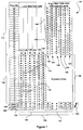
- FIG. 1 illustrates an elevator system deployment scheme 100 employing two independently moving elevator cars (Twin Cars) operating within each elevator shaft according to an aspect of the present invention.
- the system 100 represents a zoned twin elevator system.
- Each elevator car or lift operates within an elevator shaft, where each shaft is designated by a lift number 102 (e.g., 1-12).
- Elevator shafts 1-12, as indicated by 104 are illustrated at the bottom of deployment scheme 100, where a first group of elevator shafts, indicated by 106, provide transportation services to a first region of floors within a building (e.g., floors 1-20), as indicated by 108.
- a second group of elevator shafts, indicated by 110 similarly provide transportation services to a second region of floors with the building (e.g., floors 21-40), as indicated by 112.
- elevator shaft 114 comprises a twin elevator system incorporating two elevator cars that move independently of each other, where independent motion is enabled by providing separate counter weight, rope, and traction drive units for each elevator car.
- a first region 116 within shaft 114 denoted by lighter colored circles, indicate the floors (i.e., floors 1-10) that are serviced by a first elevator car (not shown) associated with the twin elevator cars.
- a second region 118 within shaft 114 denoted by the dark colored circles, indicate floors (i.e., floors 11-20) that are serviced by a second elevator car (not shown).
- Passengers or uses requiring transportation to floors in the first region 116 may enter the first elevator car on a lower ground level 120 of the building, whereas passengers or users traveling to the floors associated with the second region 118 may enter the second elevator car from the upper ground level 122.
- Access between the upper and lower ground levels may be provided, for example, by a connecting stair case, a shuttle elevator, and/or an escalator 124. All the other elevator shafts 126,128, 130, 132,134 within the first group of elevators 106 are identical to that of elevator shaft 114, described above.
- the number of elevator shafts designated for each elevator group, and the number of floors associated with each region are for purposes of illustration and not limitation, and may vary according to various elevator system design factors (e.g., building size, traffic, etc.). Also, it may be possible to increase the number of elevator cars operating within each shaft to more than two.
- One or more elevator system controllers may include various safety and monitoring procedures for ensuring that the independently moving elevator cars sharing a shaft do not come within a certain range or distance of each other for collision avoidance and safety purposes.
- elevator shaft 140 also comprises a twin elevator system incorporating two elevator cars that move independently of each other.
- a first region 142 within shaft 140 denoted by lighter colored circles, indicate the floors (i.e., floors 21-30) that are serviced by a first elevator car (not shown) associated with the twin elevator cars.
- a second region 144 within shaft 140 denoted by the dark colored circles, indicate floors (i.e., floors 31-40) that are serviced by a second elevator car (not shown).
- Passengers or users requiring transportation to floors in the first region 142 may enter the first elevator car on a lower ground level 120 of the building, whereas passengers or users traveling to floors associated with the second region 144 may enter the second elevator car from upper ground level 122.
- access between the upper and lower ground levels may be provided, for example, by a connecting stair case, a shuttle elevator, and/or an escalator 124.
- All the other elevator shafts 146, 148, 150, 152, 154 within the second group of elevators 110 are identical to that of elevator shaft 140, described above.
- the second group of elevator cars 110 comprise a express zone 158 over which the elevator cars do not stop until the upper region floors (i.e., floors 21-40) have been reached.
- the express zone facilitates an expedited service for passengers wishing to be transported to the upper floors of the building, while simultaneously providing the advantages of multiple elevator cars within each shaft.
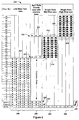
- FIG 2 illustrates an elevator system deployment scheme 200 employing two independently moving elevator cars (Twin Cars) operating within each elevator shaft according to another aspect of the present invention.
- the scheme 200 according to the present invention represents a hybrid elevator system comprising a twin elevator scheme 202 and a split twin shuttle scheme 204.
- Elevator scheme 202 is identical to that of region 106 shown in Figure 1 , where shafts 1-5, as indicated by 206, each include two elevator cars within each shaft for servicing floors 1-20.
- the split twin shuttle scheme 204 comprises a plurality of shafts 208 (i.e., shafts 6-8), where each shaft has two elevator cars that travel between a ground level and a lower and upper sky lobby 210, 212.
- a first elevator car (not shown) transports passengers between a lower ground floor level 222 and the lower sky lobby 210 (lighter colored circles). At the lower sky lobby 210, the passengers may access a bank of elevators 214 that service the mid-level floors of the building, as indicated by region 216. Similarly, a second elevator car (not shown) transports passengers between an upper ground floor level 224 and the upper sky lobby 212 (dark colored circles). At the upper sky lobby 212, the passengers may access another bank of elevators 218 that service the upper-level floors of the building, as indicated by region 220.
- elevator banks 214 and 218 are accessible from the upper level floors (i.e., floor 21 and 31, respectively).
- This provides an advantage where the shafts for these elevator banks 214, 218 do not have to extend down to the ground floor level as the elevator cars are operable from their respective sky lobbies.
- elevator shafts 9-12, indicated by 226, are not required to extend from floor 21 to the lower ground level 222.
- elevator shafts 13-16, indicated by 228, are not required to extend from floor 31 to the upper ground level 224. This provides an increase in building core space, in addition to providing more efficient elevator traffic management.
- Passengers requiring transportation to lower sky lobby 210 may enter the first elevator car on the lower ground level 222 of the building, whereas passengers traveling to upper sky lobby 212 may enter the second elevator car from the upper ground level 224.
- Access between the upper and lower ground levels 222, 224 may be provided, for example, by a connecting stair case, a shuttle elevator, and/or an escalator 230.
- elevator cars associated with elevator shafts 1-5, as indicated by 206 may be accessed from the lower or upper ground levels 222, 224 depending on whether passengers require transportation to the lower level floors, denoted by the lighter colored circles, or the upper floors, as indicated by the dark colored circles.
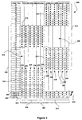
- FIG. 3 illustrates an elevator system deployment scheme 300 comprising two independently moving elevator cars (Twin Cars) operating within each elevator shaft according to an aspect of the present invention.
- the system 300 according to the present invention represents a zoned twin elevator system, where each zone has a respective express region therebetween.
- Each elevator car operates within an elevator shaft, where each shaft is designated by a lift or elevator number 302 (e.g., 1-12).
- Elevator shafts 1-12, as indicated by 304, are illustrated at the bottom of deployment scheme 300, where a first group of elevator shafts, indicated by 306, provide transportation services to a first region of floors within a building (e.g., floors 1-30), as indicated by 308.
- a second group of elevator shafts, indicated by 310 similarly provide transportation services to a second region of floors with the building (e.g., floors 11-40), as indicated by 312.
- elevator shaft 314 comprises a twin elevator system incorporating two elevator cars that move independently of each other within the shaft. Independent motion is enabled by providing separate counter weight, rope, and traction drive units for each elevator car. Other known methods known in the art of elevator motion and control may be incorporated to achieve independent movement of the elevator cars.
- an express region 319 is located between regions 316 and 318, which expedites the transportation of passengers to the upper floors of the elevator cars operating within the first group of elevator shafts indicated by 306.
- the express region 319 also simplifies the safety and control capabilities of the elevator control system. This is facilitated by the physical separation between any two elevator cars operating in their designated regions within each shaft. For example, there is a ten floor separation between the first elevator car operating within region 316 and the second elevator car operating within region 318. In such a scenario, the closest proximity between the cars operating in regions 316 and 318 is ten floors, which accounts for a relatively safe distance between the cars. If either car violates this distance, either or both elevator cars can be safely closed down using less complex sensor and control programming.
- Passengers requiring transportation to floors in the first region 316 may enter the first elevator car on a lower ground level 320 of the building, whereas passengers or users traveling to the floors associated with the second region 318 may enter the second elevator car from the upper ground level 322.
- Access between the upper and lower ground levels may be provided, for example, by a connecting stair case, a shuttle elevator, and/or an escalator 324. All the other elevator shafts 326, 328, 330, 332, 334 within the first group of elevators 306 are identical to that of elevator shaft 314, described above.
- the number of elevator shafts designated for each elevator group, and the number of floors associated with each region are for purposes of illustration and not limitation, and may vary according to various elevator system design factors (e.g., building size, traffic, etc.). Also, it may be possible to increase the number of elevator cars operating within each shaft to more than two.
- One or more elevator system controllers may include various safety and monitoring procedures for ensuring that the independently moving elevator cars sharing a shaft do not come within a certain range or distance of each other for collision avoidance and safety purposes.
- elevator shaft 340 also comprises a twin elevator system incorporating two elevator cars that move independently of each other.
- a first region 342 within shaft 340 denoted by lighter colored circles, indicate the floors (i.e., floors 21-30) that are serviced by a first elevator car (not shown) associated with the twin elevator cars.
- a second region 344 within shaft 340 denoted by the dark colored circles, indicate floors (i.e., floors 31-40) that are serviced by a second elevator car (not shown).
- an express region 356 is also located between regions 342 and 344, which expedites the transportation of passengers to the upper floors of the elevator cars operating within the first group of elevator shafts indicated by 310.
- the express region 356 also simplifies the safety and control capabilities of the elevator control system. This is facilitated by the physical separation between any two elevator cars operating in their designated regions within each shaft.
- Passengers or users requiring transportation to floors in the first region 342 may enter the first elevator car on a lower ground level 320 of the building, whereas passengers or users traveling to floors associated with the second region 344 may enter the second elevator car from upper ground level 322.
- access between the upper and lower ground levels may be provided, for example, by a connecting stair case, a shuttle elevator, and/or an escalator 324. All the other elevator shafts 346, 348, 350, 352, 354 within the second group of elevators 310 are identical to that of elevator shaft 340, described above.
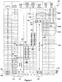
- FIG. 4 illustrates a yet another hybrid elevator system deployment scheme 400, which includes two independently moving elevator cars (Twin Cars) operating within each elevator shaft according to another aspect of the present invention.
- the scheme 400 according to the present invention represents a hybrid elevator system comprising a zoned twin elevator scheme 402, a split twin shuttle scheme 404, a double deck elevator shuttle 406, and an upper and lower zoned twin elevator scheme 408, 410.
- Elevator scheme 402 is identical to that of scheme 202 illustrated and described in connection with Figure 2 , where shafts 1-2, as indicated by 412, each include two elevator cars within each shaft for servicing floors 1-8.
- the split twin shuttle scheme 404 is identical to that of scheme 204 illustrated and described in connection with Figure 2 , and comprises a plurality of shafts 414 (i.e., shafts 3-4), where each shaft has two elevator cars that travel between a ground level and a lower mid-level and upper mid-level sky lobby 416, 418, respectively.
- a first elevator car (not shown) transports passengers between a lower ground floor level 422 and the lower mid-level sky lobby 416 (lighter colored circles) via an express zone 417.
- the passengers may access a bank of elevators 424 that service the lower mid-level floors of the building, as indicated by region 426.
- a second elevator car (not shown) transports passengers between an upper ground floor level 423 and the upper mid-level sky lobby 418 (dark colored circles) via express zone 417.
- the passengers may access another bank of elevators 430 that service the upper mid-level floors of the building, as indicated by region 432.
- elevator banks 426 and 430 are accessible from the mid level floors (i.e., floor 9 and 18, respectively).
- This provides an advantage, where the shafts corresponding to these elevator banks 426, 430 do not have to extend down to the ground floor level, as the elevator cars are operable from their respective sky lobbies (i.e., floor 9 and 18, respectively).
- elevator shafts 5-6, indicated by 426 are not required to extend from floor 9 to the lower ground level 422.
- elevator shafts 7-8, indicated by 430 are not required to extend from floor 17 to the upper ground level 423. This provides an increase in building core space, in addition to providing more efficient elevator traffic management.
- Passengers requiring transportation to lower mid-level sky lobby 416 may enter the first elevator car on the lower ground level 422 of the building, whereas passengers traveling to upper mid-level sky lobby 418 may enter the second elevator car from the upper ground level 423.
- Access between the upper and lower ground levels 422, 423 may be provided, for example, by a connecting stair case, a shuttle elevator, and/or an escalator 436.
- elevator cars associated with elevator shafts 1-2, as indicated by 412 may be accessed from the lower or upper ground levels 422, 423 depending on whether passengers require transportation to the lower level floors, denoted by the lighter colored circles, or the upper floors, as indicated by the dark colored circles.
- the double deck elevator shuttle scheme 406 illustrated in Figure 4 comprises a plurality of shafts (i.e., 9-10), as indicated by 440.
- Each shaft includes a double deck elevator car (not shown) which comprises a lower deck elevator car coupled to an upper deck elevator car.
- the double deck elevator car When the double deck elevator car is at any given floor, the upper deck elevator car concurrently serves the floor immediately above the floor served by the lower deck elevator car.
- the double deck elevator car associated with each of the plurality of shafts 440 provides passenger transportation between the upper and lower ground floor levels 422, 423, and a first and second upper-level lobby 442, 444, respectively.
- Zoned twin scheme 408 comprises a top down zoned twin system, whereby floor region 450B is serviced by a first elevator car operating within each shaft (i.e., Lift No. 11-12) and floor region 452B is, similarly, serviced by a second elevator car operating within each shaft (i.e., Lift No. 11-12).
- Zoned twin scheme 410 comprises floor region 450A, which is serviced by a first elevator car operating within each shaft (i.e., Lift No. 13-14) and floor region 452A is, similarly, serviced by a second elevator car operating within each shaft (i.e., Lift No. 11-12) of the zoned twin system.
- Passengers requiring access to floor regions 450B and 452A may access elevator banks 446 and 448 by taking one of the double deck elevator cars (i.e., Lift No. 9 or 10) from upper ground level 423 to the second upper-level lobby 444.
- floor regions 450A and 452B may be accessed via elevator banks 446 and 448 by taking one of the double deck elevator cars (i.e., Lift No. 9 or 10) from lower ground level 422 to the first upper-level lobby 442.
- the upper and lower zoned twin elevator schemes 408, 410 are accessed by the double deck elevator shuttle scheme 406 and, thus, provide an efficient means of traffic management, whereby passengers requiring service to the upper floors of the building are transported via express zone 456 to the upper-level lobbies 442, 444.
- This also enables the elevator shafts within elevator banks 446 and 448 to extend only as far down as the lowest floor for which they provide service.
- the elevator shafts associated with elevator bank 446 may only need to extend as far "floor 28," which facilitates the use of core building space below this floor (i.e., floor 28).
- the shafts of elevator bank 448 may only need to extend from the top region of the building to "floor 37." Hence, the use of core building space below "floor 37" is mad made available.
- the number of floors and elevator shafts (i.e., indicated by lift no.) illustrated in connection with Figure 4 are for purposes of illustration and not of limitation. For example, the number of floors and elevator shafts may be increased in accordance with traffic management, elevator system design principles, and/or other factors.
- FIG. 5 illustrates an elevator deployment scheme 500 for providing a combination of goods and passenger transportation according to an aspect of the present invention.
- transportation of both goods and passengers is provided by two independently moving elevator cars operating within each shaft, as indicated by 502.
- Each elevator shaft comprises a lower and an upper elevator car, where transportation provided by the lower elevator car is indicated by the lighter colored circles and service provided by upper car is identified by the dark colored circles.
- Transportation between the ground floor level and a floor immediately below the top floor (i.e., 15 th floor), as indicated by 504 is provided by both the upper and lower elevator cars moving within each shaft.
- Transportation to the basement 506 is provided by the lower elevator car only.
- transportation to the top floor 508 i.e., 16 th floor
- the upper elevator may move into the virtual landing area 510, allowing the lower elevator car to service or provide transportation to the top floor 508.
- the virtual landing may comprise a location in the hoistway or elevator shaft, where one of the twin elevator cars can be moved in order to make way for the other elevator car operating within the same elevator shaft.
- the lighter colored circles designate the floors that receive transportation services from the lower elevator cars within each of elevator shafts 1-6, defined by 502.
- the lower elevator cars may be used as a goods or services elevator.
- the darker colored circles designate the floors that receive transportation services from the upper elevator cars within each of elevator shafts 1-6, defined by 502, whereby the upper elevator cars may provide passenger transportation.
- the minimum permissible safe distance between the upper and lower elevator cars may be a single floor.
- the lower elevator car may be on the 5 th floor and the upper elevator car may be directly above it on the 6 th floor.
- the control mechanisms for controlling and maintaining a safe distance between the upper and lower elevator cars may depend on the elevator controller system (not shown) and sensory technology (not shown) employed. For example, based on safety and other considerations, a minimum safe distance of two or more floors may be required between the elevator cars.
- the elevator controller may also provide a priority based elevator dispatching process, that assigns a higher priority to passenger transportation relative to goods or services transportation. Therefore, the controller system may ensure that the elevator shafts are mainly free and not obstructed by the lower goods elevator cars during periods when passenger traffic is high (e.g., 5pm in an office building).
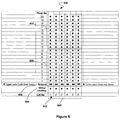
- FIG. 6 illustrates an elevator deployment scheme 600 comprising a zoned twin elevator system according to an aspect of the present invention.
- the zoned twin elevator is identical to the zoned twin system described and illustrated in connection with Figure 1 , accept that deployment scheme 600 comprises a single ground floor level 602 (i.e., no upper and lower ground floor level) and a virtual landing 604 that is located beneath ground level 602.
- Each of the elevator shafts, indicated by 606, include two elevator cars (not shown) independent operating within them.
- each elevator operates within a region or zone.
- a first elevator car provides transportation between the ground floor 602 and the 10 th floor of the building, as indicated by region 608, and designated by the lighter colored circles.
- a second elevator car provides transportation from the ground floor 602 to the upper floors of the building (i.e., floors 11-20), as indicated by region 610, and designated by the darker colored circles.
- both the first and second elevator cars may load passengers from the ground level 602.
- the first elevator cars operating in region 608 may load passengers from their rear doors and the second elevator cars operating in region 610 load passengers from their front doors.
- only one of the elevator cars operating within each shaft can access the ground floor 602 for the purpose of loading passengers. If, for example, the second elevator car operating in region 610 is assigned to load passengers from the ground floor 602, the first elevator car operating in region 608 must be relocated to the virtual landing 604 in order to allow the second elevator to access the ground floor 602.
- the second elevator car should be operating within region 610 or be located at a minimum safe distance above the first elevator car in compliance with the safety standards and mechanisms in place.
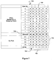
- FIG. 7 illustrates an elevator deployment scheme 700 comprising a zoned twin elevator system according to an aspect of the present invention.
- Each of the elevator shafts, indicated by 702 include two elevator cars (not shown) independent operating within them.
- each elevator operates within a region or zone.
- a first elevator car provides transportation between the ground floor 706 and the top floor of the building, as indicated by region 708, and designated by the dark colored circles.
- a second elevator car provides transportation from the ground floor 706 to the sub-ground level floors of the building (i.e., floors P1-P4), as indicated by region 710, and designated by the lighter colored circles.
- the sub-ground level floors, indicated by 710 may, for example, be parking levels underneath the building.
- the floor levels located above ground level 706, may for example, be residential apartments, offices, and/or commercial shopping floors.
- elevator deployment scheme 700 comprises a single ground floor level 706 (i.e., no upper and lower ground floor level). Both the first and second elevator cars within each shaft may load passengers from the ground level 706. The first elevator cars operating in region 708 may load passengers from their front doors and the second elevator cars operating in region 710 (i.e., parking levels) may load passengers from their rear doors. At any given instant, only one of the elevator cars operating within each shaft can access the ground floor 706 for the purpose of loading passengers.
- the first elevator car operating in region 708 should remain operating at a minimum safe distance from the second elevator car in region 708.
- the second elevator car should be operating within region 710 and be located at a minimum safe distance below the first elevator car.
- This deployment scheme 700 increases the traffic flow significantly by allowing each of the twin elevator cars to operate in two separate regions 708, 710 that have little or no overlap within each shaft (e.g., shaft 702).
Description
- The present invention relates to a system deploying elevator systems, in particular, the deployment of a plurality of deployment schemes associated with twin elevator systems.
- In multi-storey buildings, one of the main objectives is to efficiently transport passengers to various floors using an elevator system. In designing, developing, and deploying elevator systems, particular attention should be paid to the portion of the building core that is dedicated to the elevator system. For example, as the number of elevator shafts are increased to meet the demands of higher buildings, maximizing real estate space as a commodity is also a main concern that must be addressed. Therefore, the object is to try and minimize the required number of elevator shafts that are deployed within an elevator system, while also trying to effectively meet the transportation needs of passengers and freight within the building. For example, a poorly designed elevator system may cause unacceptable delays for passengers trying to reach a desired floor. However, solutions to try and reduce the number of shafts and improve service have included higher elevator travel speeds, shorter door opening/closing times, advanced control systems, express elevators, splitting buildings into zones, etc. These solutions, while relatively successful in addressing some of the challenges, may not be acceptable by the user. These reasons may include a feeling of unease when elevators accelerate, doors quickly closing, or difficulties that may be experienced as the result of using a complicated system, where passengers may have to change one or several times to get to a desired floor.
- Despite the mentioned optimization measures, it is evident that the largest part or portion of the elevator shaft is not used when the elevator car is in another part of the shaft. One solution attempting to capitalize on this is the double-decker elevator. However, some of the disadvantages of such a system are the large scale drives and power supplies that become necessary for accelerating such a large mass. Also, as the cars are semi-connected, the delays for passengers waiting for other passengers to exit and enter the elevator may be more as a result of two floors being simultaneously served. Moreover, the stories of the building would have to be virtually equidistant, which is an expensive objective to meet in a building.
GB 2 324 170 AUS2004/173417A1 discloses elevator systems according to the state of the art.
US 2004/0173417 A1 relates to an elevator system in tall buildings, which comprises at least one first elevator shaft and at least one second elevator shaft. - It is therefore an object of the present invention to provide an elevator system that is capable of effectively maximizing an elevator shaft by accommodating more than one independently controllable elevator car within a shaft.
- It is another object of the present invention to deploy various elevator schemes using more than one elevator car within each elevator shaft based on different buildings, where each building comprises a different number of floors and elevator shafts.
- While the invention is defined in the independent claims, further aspects of the invention are set forth in the dependent claims, the drawings and the following description.
- The present invention provides elevator system architectures and methods that employ the use of two elevator cars within a single elevator shaft, where each of the two elevator cars move independently of each other within the shaft.
- An aspect of the present invention provides an elevator system having the features of
claim 1. -
-
Figure 1 illustrates an elevator system deployment scheme employing two independently moving elevator cars operating within each elevator shaft according to an aspect of the present invention, where the lower floors are serviced by a first group of elevator cars, and the upper floors are serviced by a second group via an express zone. -
Figure 2 illustrates an elevator system deployment scheme employing two independently moving elevator cars operating within each elevator shaft according to an aspect of the present invention, where the upper floors are serviced by two shuttle cars operating within the same elevator shaft. -
Figure 3 illustrates an elevator system deployment scheme employing two independently moving elevator cars operating within each elevator shaft according to an aspect of the present invention, where an elevator motion-free zone is established within each shaft. -
Figure 4 illustrates an elevator system deployment scheme employing two independently moving elevator cars operating within each elevator shaft according to an aspect of the present invention, where the upper floors are serviced by double deck shuttles for transporting passengers to lobbies that provide access to the upper floors that utilize the two independently moving elevator cars operating within each elevator shaft. -
Figure 5 illustrates an elevator system deployment scheme employing two independently moving elevator cars operating within each elevator shaft according to an aspect of the present invention, where an upper floor virtual landing is provided. -
Figure 6 illustrates an elevator system deployment scheme employing two independently moving elevator cars operating within each elevator shaft according to an aspect of the present invention, where a lower ground level virtual landing is provided. -
Figure 7 illustrates an elevator system deployment scheme employing two independently moving elevator cars operating within each elevator shaft according to an aspect of the present invention, where one of the two independently moving elevator cars services sub-ground level floors, and the other elevator car accordingly services the floors above ground level. -
Figure 1 illustrates an elevatorsystem deployment scheme 100 employing two independently moving elevator cars (Twin Cars) operating within each elevator shaft according to an aspect of the present invention. Thesystem 100 according to the present invention represents a zoned twin elevator system. Each elevator car or lift operates within an elevator shaft, where each shaft is designated by a lift number 102 (e.g., 1-12). Elevator shafts 1-12, as indicated by 104, are illustrated at the bottom ofdeployment scheme 100, where a first group of elevator shafts, indicated by 106, provide transportation services to a first region of floors within a building (e.g., floors 1-20), as indicated by 108. A second group of elevator shafts, indicated by 110, similarly provide transportation services to a second region of floors with the building (e.g., floors 21-40), as indicated by 112. - Within the first group of elevator shafts, indicated by 106,
elevator shaft 114 comprises a twin elevator system incorporating two elevator cars that move independently of each other, where independent motion is enabled by providing separate counter weight, rope, and traction drive units for each elevator car. Afirst region 116 withinshaft 114, denoted by lighter colored circles, indicate the floors (i.e., floors 1-10) that are serviced by a first elevator car (not shown) associated with the twin elevator cars. Asecond region 118 withinshaft 114, denoted by the dark colored circles, indicate floors (i.e., floors 11-20) that are serviced by a second elevator car (not shown). Passengers or uses requiring transportation to floors in thefirst region 116 may enter the first elevator car on alower ground level 120 of the building, whereas passengers or users traveling to the floors associated with thesecond region 118 may enter the second elevator car from theupper ground level 122. Access between the upper and lower ground levels may be provided, for example, by a connecting stair case, a shuttle elevator, and/or anescalator 124. All the other elevator shafts 126,128, 130, 132,134 within the first group ofelevators 106 are identical to that ofelevator shaft 114, described above. - The number of elevator shafts designated for each elevator group, and the number of floors associated with each region (e.g., floors 1-10 in the first region 116) are for purposes of illustration and not limitation, and may vary according to various elevator system design factors (e.g., building size, traffic, etc.). Also, it may be possible to increase the number of elevator cars operating within each shaft to more than two.
- One or more elevator system controllers (not shown) may include various safety and monitoring procedures for ensuring that the independently moving elevator cars sharing a shaft do not come within a certain range or distance of each other for collision avoidance and safety purposes.
- Within the second group of elevator shafts, indicated by 110,
elevator shaft 140 also comprises a twin elevator system incorporating two elevator cars that move independently of each other. Afirst region 142 withinshaft 140, denoted by lighter colored circles, indicate the floors (i.e., floors 21-30) that are serviced by a first elevator car (not shown) associated with the twin elevator cars. Asecond region 144 withinshaft 140, denoted by the dark colored circles, indicate floors (i.e., floors 31-40) that are serviced by a second elevator car (not shown). Passengers or users requiring transportation to floors in thefirst region 142 may enter the first elevator car on alower ground level 120 of the building, whereas passengers or users traveling to floors associated with thesecond region 144 may enter the second elevator car fromupper ground level 122. As previously described, access between the upper and lower ground levels may be provided, for example, by a connecting stair case, a shuttle elevator, and/or anescalator 124. All theother elevator shafts elevators 110 are identical to that ofelevator shaft 140, described above. The second group ofelevator cars 110 comprise aexpress zone 158 over which the elevator cars do not stop until the upper region floors (i.e., floors 21-40) have been reached. - Use of two elevator cars within each shaft, and the provision of an
express zone 158, reduces the number of elevator shafts required in comparison to systems employing single elevator cars operating within each shaft for a given traffic or utilization factor. The express zone facilitates an expedited service for passengers wishing to be transported to the upper floors of the building, while simultaneously providing the advantages of multiple elevator cars within each shaft. -
Figure 2 illustrates an elevatorsystem deployment scheme 200 employing two independently moving elevator cars (Twin Cars) operating within each elevator shaft according to another aspect of the present invention. Thescheme 200 according to the present invention represents a hybrid elevator system comprising atwin elevator scheme 202 and a splittwin shuttle scheme 204.Elevator scheme 202 is identical to that ofregion 106 shown inFigure 1 , where shafts 1-5, as indicated by 206, each include two elevator cars within each shaft for servicing floors 1-20. The splittwin shuttle scheme 204 comprises a plurality of shafts 208 (i.e., shafts 6-8), where each shaft has two elevator cars that travel between a ground level and a lower andupper sky lobby ground floor level 222 and the lower sky lobby 210 (lighter colored circles). At thelower sky lobby 210, the passengers may access a bank ofelevators 214 that service the mid-level floors of the building, as indicated by region 216. Similarly, a second elevator car (not shown) transports passengers between an upperground floor level 224 and the upper sky lobby 212 (dark colored circles). At theupper sky lobby 212, the passengers may access another bank ofelevators 218 that service the upper-level floors of the building, as indicated byregion 220. - As illustrated in
Figure 2 ,elevator banks floor elevator banks floor 21 to thelower ground level 222. Similarly, elevator shafts 13-16, indicated by 228, are not required to extend fromfloor 31 to theupper ground level 224. This provides an increase in building core space, in addition to providing more efficient elevator traffic management. - Passengers requiring transportation to
lower sky lobby 210 may enter the first elevator car on thelower ground level 222 of the building, whereas passengers traveling toupper sky lobby 212 may enter the second elevator car from theupper ground level 224. Access between the upper andlower ground levels escalator 230. Also, elevator cars associated with elevator shafts 1-5, as indicated by 206, may be accessed from the lower orupper ground levels -
Figure 3 illustrates an elevatorsystem deployment scheme 300 comprising two independently moving elevator cars (Twin Cars) operating within each elevator shaft according to an aspect of the present invention. Thesystem 300 according to the present invention represents a zoned twin elevator system, where each zone has a respective express region therebetween. - Each elevator car operates within an elevator shaft, where each shaft is designated by a lift or elevator number 302 (e.g., 1-12). Elevator shafts 1-12, as indicated by 304, are illustrated at the bottom of
deployment scheme 300, where a first group of elevator shafts, indicated by 306, provide transportation services to a first region of floors within a building (e.g., floors 1-30), as indicated by 308. A second group of elevator shafts, indicated by 310, similarly provide transportation services to a second region of floors with the building (e.g., floors 11-40), as indicated by 312. - Within the first group of elevator shafts, indicated by 306,
elevator shaft 314 comprises a twin elevator system incorporating two elevator cars that move independently of each other within the shaft. Independent motion is enabled by providing separate counter weight, rope, and traction drive units for each elevator car. Other known methods known in the art of elevator motion and control may be incorporated to achieve independent movement of the elevator cars. Afirst region 316 withinshaft 314, denoted by lighter colored circles, indicates the floors (i.e., floors 1-10) that are serviced by a first elevator car (not shown), and asecond region 318 withinshaft 314, denoted by the dark colored circles, illustrates floors (i.e., floors 21-30) that are serviced by a second elevator car (not shown). As illustrated in the figure, anexpress region 319 is located betweenregions express region 319 also simplifies the safety and control capabilities of the elevator control system. This is facilitated by the physical separation between any two elevator cars operating in their designated regions within each shaft. For example, there is a ten floor separation between the first elevator car operating withinregion 316 and the second elevator car operating withinregion 318. In such a scenario, the closest proximity between the cars operating inregions - Passengers requiring transportation to floors in the
first region 316 may enter the first elevator car on alower ground level 320 of the building, whereas passengers or users traveling to the floors associated with thesecond region 318 may enter the second elevator car from theupper ground level 322. Access between the upper and lower ground levels may be provided, for example, by a connecting stair case, a shuttle elevator, and/or anescalator 324. All theother elevator shafts elevators 306 are identical to that ofelevator shaft 314, described above. - The number of elevator shafts designated for each elevator group, and the number of floors associated with each region (e.g., floors 1-10 in the first region 316) are for purposes of illustration and not limitation, and may vary according to various elevator system design factors (e.g., building size, traffic, etc.). Also, it may be possible to increase the number of elevator cars operating within each shaft to more than two.
- One or more elevator system controllers (not shown) may include various safety and monitoring procedures for ensuring that the independently moving elevator cars sharing a shaft do not come within a certain range or distance of each other for collision avoidance and safety purposes.
- Within the second group of elevator shafts, indicated by 310,
elevator shaft 340 also comprises a twin elevator system incorporating two elevator cars that move independently of each other. Afirst region 342 withinshaft 340, denoted by lighter colored circles, indicate the floors (i.e., floors 21-30) that are serviced by a first elevator car (not shown) associated with the twin elevator cars. Asecond region 344 withinshaft 340, denoted by the dark colored circles, indicate floors (i.e., floors 31-40) that are serviced by a second elevator car (not shown). As illustrated in the figure, anexpress region 356 is also located betweenregions express region 356 also simplifies the safety and control capabilities of the elevator control system. This is facilitated by the physical separation between any two elevator cars operating in their designated regions within each shaft. - Passengers or users requiring transportation to floors in the
first region 342 may enter the first elevator car on alower ground level 320 of the building, whereas passengers or users traveling to floors associated with thesecond region 344 may enter the second elevator car fromupper ground level 322. As previously described, access between the upper and lower ground levels may be provided, for example, by a connecting stair case, a shuttle elevator, and/or anescalator 324. All theother elevator shafts elevators 310 are identical to that ofelevator shaft 340, described above. -
Figure 4 illustrates a yet another hybrid elevatorsystem deployment scheme 400, which includes two independently moving elevator cars (Twin Cars) operating within each elevator shaft according to another aspect of the present invention. Thescheme 400 according to the present invention represents a hybrid elevator system comprising a zonedtwin elevator scheme 402, a splittwin shuttle scheme 404, a doubledeck elevator shuttle 406, and an upper and lower zonedtwin elevator scheme Elevator scheme 402 is identical to that ofscheme 202 illustrated and described in connection withFigure 2 , where shafts 1-2, as indicated by 412, each include two elevator cars within each shaft for servicing floors 1-8. - The split
twin shuttle scheme 404 is identical to that ofscheme 204 illustrated and described in connection withFigure 2 , and comprises a plurality of shafts 414 (i.e., shafts 3-4), where each shaft has two elevator cars that travel between a ground level and a lower mid-level and uppermid-level sky lobby ground floor level 422 and the lower mid-level sky lobby 416 (lighter colored circles) via an express zone 417. At the lowermid-level sky lobby 416, the passengers may access a bank of elevators 424 that service the lower mid-level floors of the building, as indicated byregion 426. Similarly, a second elevator car (not shown) transports passengers between an upperground floor level 423 and the upper mid-level sky lobby 418 (dark colored circles) via express zone 417. At the uppermid-level sky lobby 418, the passengers may access another bank ofelevators 430 that service the upper mid-level floors of the building, as indicated byregion 432. - As illustrated in
Figure 4 ,elevator banks floor elevator banks floor floor 9 to thelower ground level 422. Similarly, elevator shafts 7-8, indicated by 430, are not required to extend fromfloor 17 to theupper ground level 423. This provides an increase in building core space, in addition to providing more efficient elevator traffic management. - Passengers requiring transportation to lower
mid-level sky lobby 416 may enter the first elevator car on thelower ground level 422 of the building, whereas passengers traveling to uppermid-level sky lobby 418 may enter the second elevator car from theupper ground level 423. Access between the upper andlower ground levels escalator 436. Also, elevator cars associated with elevator shafts 1-2, as indicated by 412, may be accessed from the lower orupper ground levels - The double deck
elevator shuttle scheme 406 illustrated inFigure 4 comprises a plurality of shafts (i.e., 9-10), as indicated by 440. Each shaft includes a double deck elevator car (not shown) which comprises a lower deck elevator car coupled to an upper deck elevator car. When the double deck elevator car is at any given floor, the upper deck elevator car concurrently serves the floor immediately above the floor served by the lower deck elevator car. The double deck elevator car associated with each of the plurality ofshafts 440, provides passenger transportation between the upper and lowerground floor levels level lobby - At the first and second upper-
level lobby elevator banks twin elevator schemes elevator banks twin scheme 408 comprises a top down zoned twin system, wherebyfloor region 450B is serviced by a first elevator car operating within each shaft (i.e., Lift No. 11-12) andfloor region 452B is, similarly, serviced by a second elevator car operating within each shaft (i.e., Lift No. 11-12). Zonedtwin scheme 410 comprisesfloor region 450A, which is serviced by a first elevator car operating within each shaft (i.e., Lift No. 13-14) andfloor region 452A is, similarly, serviced by a second elevator car operating within each shaft (i.e., Lift No. 11-12) of the zoned twin system. - Passengers requiring access to
floor regions elevator banks upper ground level 423 to the second upper-level lobby 444. Similarly,floor regions elevator banks lower ground level 422 to the first upper-level lobby 442. The upper and lower zonedtwin elevator schemes elevator shuttle scheme 406 and, thus, provide an efficient means of traffic management, whereby passengers requiring service to the upper floors of the building are transported viaexpress zone 456 to the upper-level lobbies 442, 444. This also enables the elevator shafts withinelevator banks elevator bank 446 may only need to extend as far "floor 28," which facilitates the use of core building space below this floor (i.e., floor 28). Also, the shafts ofelevator bank 448 may only need to extend from the top region of the building to "floor 37." Hence, the use of core building space below "floor 37" is mad made available. The number of floors and elevator shafts (i.e., indicated by lift no.) illustrated in connection withFigure 4 are for purposes of illustration and not of limitation. For example, the number of floors and elevator shafts may be increased in accordance with traffic management, elevator system design principles, and/or other factors. -
Figure 5 illustrates anelevator deployment scheme 500 for providing a combination of goods and passenger transportation according to an aspect of the present invention. In the embodiment ofFigure 5 , transportation of both goods and passengers is provided by two independently moving elevator cars operating within each shaft, as indicated by 502. Each elevator shaft comprises a lower and an upper elevator car, where transportation provided by the lower elevator car is indicated by the lighter colored circles and service provided by upper car is identified by the dark colored circles. Transportation between the ground floor level and a floor immediately below the top floor (i.e., 15th floor), as indicated by 504, is provided by both the upper and lower elevator cars moving within each shaft. Transportation to thebasement 506 is provided by the lower elevator car only. Also, transportation to the top floor 508 (i.e., 16th floor) is normally provided by the upper elevator car. However, if avirtual landing area 510 is provided, the upper elevator may move into thevirtual landing area 510, allowing the lower elevator car to service or provide transportation to thetop floor 508. The virtual landing may comprise a location in the hoistway or elevator shaft, where one of the twin elevator cars can be moved in order to make way for the other elevator car operating within the same elevator shaft. - For illustrative purposes, the lighter colored circles designate the floors that receive transportation services from the lower elevator cars within each of elevator shafts 1-6, defined by 502. The lower elevator cars may be used as a goods or services elevator. The darker colored circles designate the floors that receive transportation services from the upper elevator cars within each of elevator shafts 1-6, defined by 502, whereby the upper elevator cars may provide passenger transportation.
- As both elevator cars within each elevator shaft have access to a common set of floors within a building, the minimum permissible safe distance between the upper and lower elevator cars may be a single floor. For example, the lower elevator car may be on the 5th floor and the upper elevator car may be directly above it on the 6th floor. The control mechanisms for controlling and maintaining a safe distance between the upper and lower elevator cars may depend on the elevator controller system (not shown) and sensory technology (not shown) employed. For example, based on safety and other considerations, a minimum safe distance of two or more floors may be required between the elevator cars.
- The elevator controller may also provide a priority based elevator dispatching process, that assigns a higher priority to passenger transportation relative to goods or services transportation. Therefore, the controller system may ensure that the elevator shafts are mainly free and not obstructed by the lower goods elevator cars during periods when passenger traffic is high (e.g., 5pm in an office building).
-
Figure 6 illustrates anelevator deployment scheme 600 comprising a zoned twin elevator system according to an aspect of the present invention. The zoned twin elevator is identical to the zoned twin system described and illustrated in connection withFigure 1 , accept thatdeployment scheme 600 comprises a single ground floor level 602 (i.e., no upper and lower ground floor level) and avirtual landing 604 that is located beneathground level 602. Each of the elevator shafts, indicated by 606, include two elevator cars (not shown) independent operating within them. As previously described, each elevator operates within a region or zone. For example, within each shaft (e.g., shaft 612), a first elevator car provides transportation between theground floor 602 and the 10th floor of the building, as indicated byregion 608, and designated by the lighter colored circles. Also within each shaft, a second elevator car provides transportation from theground floor 602 to the upper floors of the building (i.e., floors 11-20), as indicated byregion 610, and designated by the darker colored circles. - As illustrated in
Figure 6 , both the first and second elevator cars may load passengers from theground level 602. The first elevator cars operating inregion 608 may load passengers from their rear doors and the second elevator cars operating inregion 610 load passengers from their front doors. At any given instant, only one of the elevator cars operating within each shaft can access theground floor 602 for the purpose of loading passengers. If, for example, the second elevator car operating inregion 610 is assigned to load passengers from theground floor 602, the first elevator car operating inregion 608 must be relocated to thevirtual landing 604 in order to allow the second elevator to access theground floor 602. - If the first elevator car operating in
region 608 is assigned to load passengers from theground floor 602, the second elevator car should be operating withinregion 610 or be located at a minimum safe distance above the first elevator car in compliance with the safety standards and mechanisms in place. -
Figure 7 illustrates anelevator deployment scheme 700 comprising a zoned twin elevator system according to an aspect of the present invention. Each of the elevator shafts, indicated by 702, include two elevator cars (not shown) independent operating within them. As previously described, each elevator operates within a region or zone. For example, within each shaft (e.g., shaft 704), a first elevator car provides transportation between theground floor 706 and the top floor of the building, as indicated byregion 708, and designated by the dark colored circles. Also within each shaft, a second elevator car provides transportation from theground floor 706 to the sub-ground level floors of the building (i.e., floors P1-P4), as indicated byregion 710, and designated by the lighter colored circles. The sub-ground level floors, indicated by 710, may, for example, be parking levels underneath the building. The floor levels located aboveground level 706, may for example, be residential apartments, offices, and/or commercial shopping floors. - As illustrated and described in connection with
Figure 6 ,elevator deployment scheme 700 comprises a single ground floor level 706 (i.e., no upper and lower ground floor level). Both the first and second elevator cars within each shaft may load passengers from theground level 706. The first elevator cars operating inregion 708 may load passengers from their front doors and the second elevator cars operating in region 710 (i.e., parking levels) may load passengers from their rear doors. At any given instant, only one of the elevator cars operating within each shaft can access theground floor 706 for the purpose of loading passengers. If, for example, the second elevator car operating inregion 710 is assigned to load passengers from theground floor 706 for the purpose of transporting them to the parking area, the first elevator car operating inregion 708 should remain operating at a minimum safe distance from the second elevator car inregion 708. - If the first elevator car operating in
region 708 is assigned to load passengers from theground floor 706, the second elevator car should be operating withinregion 710 and be located at a minimum safe distance below the first elevator car. By operating two elevators within a single shaft, more efficient use of the elevator shaft and, therefore, more passenger transportation is facilitated. As illustrated inFigure 7 , while passengers are being transported to the upper floors, the elevator shaft is simultaneously utilized for transporting our passengers to the parking area. Thisdeployment scheme 700 increases the traffic flow significantly by allowing each of the twin elevator cars to operate in twoseparate regions - In addition to the embodiments of the aspects of the present invention described above, those of skill in the art will be able to arrive at a variety of other arrangements and steps which, if not explicitly described in this document, nevertheless embody the invention and fall within the scope of the appended claims. For example, the ordering of method steps is not necessarily fixed, but may be capable of being modified without departing from the scope of the present invention.
Claims (15)
- An elevator system (100, 200, 300, 400, 500, 600, 700) of a building comprising:a first region (116);a second region (118), wherein said second region is disposed at least partially above said first region;a first elevator car for moving within said first region;a second elevator car for moving within said second region, wherein the first and second elevator cars are disposed within a first elevator shaft (106, 206, 306, 412, 502, 606, 702) and movably controlled independently of each other; andat least one transfer lobby at which passengers can access the first elevator car and the second elevator car.
- An elevator system (100, 200, 300, 400, 500, 600, 700) according to claim 1, wherein the first region (116) and the second region (118) do not overlap.
- An elevator system (100, 200, 300, 400, 500, 600, 700) according to claim 1, wherein the first region (116) and the second region (118) at least partially overlap.
- An elevator system (100, 200, 300, 400, 500, 600, 700) according to claim 1, further comprising:a third region arranged above the second region (118);a third elevator car for moving within said third region, wherein the third elevator car is disposed within the first elevator shaft (106, 206, 306, 412, 502, 606, 702) and is movably controlled independently of said first and second cars.
- An elevator system (100, 200, 300, 400, 500, 600, 700) according to claim 1, further comprising:a second elevator shaft; andan express elevator shuttle moving within the second elevator shaft.
- An elevator system (100, 200, 300, 400, 500, 600, 700) according to claim 5, wherein the express elevator shuttle exclusively serves the at least one transfer lobby from a ground floor transfer lobby.
- An elevator system (100, 200, 300, 400, 500, 600, 700) according to claim 6, wherein the express shuttle comprises a select one of a single express elevator car, two express elevator cars, and a double deck elevator car.
- An elevator system (100, 200, 300, 400, 500, 600, 700) according to claim 5, wherein the express shuttle comprises a select one of a single express elevator car, two express elevator cars, and a double deck elevator car.
- An elevator system (100, 200, 300, 400, 500, 600, 700) according to claim 1, wherein the at least one transfer lobby comprises an upper transfer floor and a lower transfer floor connected by a select one of a stair case, a shuttle elevator, and an escalator.
- A method of operating an elevator system (100, 200, 300, 400, 500, 600, 700) comprising a first and a second independently operable elevator car within each at least one elevator shaft (106, 206, 306, 412, 502, 606, 702) within a building, the method comprising:providing passenger transportation to a first region (116) using the first elevator car within the at least one elevator shaft, said first region defined by a plurality of floors of said building, said first region extending between and including a first floor and a second floor;providing passenger transportation to a second region (118) using the second car within the at least one elevator shaft, said second region defined by a plurality of floors of said building, said second region extending between and including a third floor and a fourth floor;characterised by further comprisingcontrolling the loading of the first elevator car from the first floor by moving the second elevator to a virtual landing region, said virtual landing region located outside of said first and said second region.
- The method according to claim 10, wherein the first floor is a bottom floor of said first region.
- The method according to claim 10, wherein the first floor is a top floor of said first region.
- The method according to claim 10, wherein said third floor and said first floor are the same floor.
- The method according to claim 13, wherein said fourth floor and said second floor are the same floor.
- The method according to claim 10, wherein said third floor is outside of said first region.
Applications Claiming Priority (2)
| Application Number | Priority Date | Filing Date | Title |
|---|---|---|---|
| US11/207,539 US7841450B2 (en) | 2005-08-19 | 2005-08-19 | Twin elevator systems |
| EP06801074.3A EP1915308B1 (en) | 2005-08-19 | 2006-08-09 | Twin elevator systems |
Related Parent Applications (2)
| Application Number | Title | Priority Date | Filing Date |
|---|---|---|---|
| EP06801074.3A Division EP1915308B1 (en) | 2005-08-19 | 2006-08-09 | Twin elevator systems |
| EP06801074.3A Division-Into EP1915308B1 (en) | 2005-08-19 | 2006-08-09 | Twin elevator systems |
Publications (2)
| Publication Number | Publication Date |
|---|---|
| EP2860140A1 EP2860140A1 (en) | 2015-04-15 |
| EP2860140B1 true EP2860140B1 (en) | 2016-03-30 |
Family
ID=37766437
Family Applications (2)
| Application Number | Title | Priority Date | Filing Date |
|---|---|---|---|
| EP06801074.3A Not-in-force EP1915308B1 (en) | 2005-08-19 | 2006-08-09 | Twin elevator systems |
| EP14003906.6A Not-in-force EP2860140B1 (en) | 2005-08-19 | 2006-08-09 | Zoned elevator system |
Family Applications Before (1)
| Application Number | Title | Priority Date | Filing Date |
|---|---|---|---|
| EP06801074.3A Not-in-force EP1915308B1 (en) | 2005-08-19 | 2006-08-09 | Twin elevator systems |
Country Status (8)
| Country | Link |
|---|---|
| US (5) | US7841450B2 (en) |
| EP (2) | EP1915308B1 (en) |
| JP (1) | JP2009504540A (en) |
| AU (1) | AU2006283763A1 (en) |
| BR (1) | BRPI0615359A2 (en) |
| CA (3) | CA2751637C (en) |
| ES (1) | ES2535711T3 (en) |
| WO (1) | WO2007024488A2 (en) |
Families Citing this family (42)
| Publication number | Priority date | Publication date | Assignee | Title |
|---|---|---|---|---|
| SG111198A1 (en) * | 2003-10-09 | 2005-05-30 | Inventio Ag | Lift installation for zonal operation in a building, method for zonal operation of such a lift installation and method for modernisation of a lift installation |
| US7650966B2 (en) * | 2004-06-21 | 2010-01-26 | Otis Elevator Company | Elevator system including multiple cars in a hoistway, destination entry control and parking positions |
| EP1666398B1 (en) * | 2004-12-01 | 2013-06-19 | Inventio AG | Method for transporting passengers in a building |
| EP1666399B1 (en) * | 2004-12-01 | 2012-10-31 | Inventio AG | Method for transporting passengers in a building |
| JP5031577B2 (en) * | 2004-12-16 | 2012-09-19 | オーチス エレベータ カンパニー | Elevator system with multiple cars in hoistway |
| EP1843963B1 (en) * | 2004-12-29 | 2012-05-02 | Otis Elevator Company | Compensation in an elevator system having multiple cars within a single hoistway |
| US7784588B2 (en) * | 2005-02-04 | 2010-08-31 | Otis Elevator Company | Calls assigned to one of two cars in a hoistway to minimize delay imposed on either car |
| AU2005327255B2 (en) * | 2005-02-04 | 2009-02-12 | Otis Elevator Company | Announcements indicating one car is waiting for another car in the same hoistway |
| WO2006088457A1 (en) * | 2005-02-17 | 2006-08-24 | Otis Elevator Company | Communicating to elevator passengers re car movement to pit or overhead |
| US7819228B2 (en) * | 2005-02-17 | 2010-10-26 | Otis Elevator Company | Collison prevention in hoistway with two elevator cars |
| CN101128383B (en) * | 2005-02-25 | 2010-10-13 | 奥蒂斯电梯公司 | Elevator car having an angled underslung roping arrangement |
| US7841450B2 (en) * | 2005-08-19 | 2010-11-30 | Thyssenkrupp Elevator Capital Corporation | Twin elevator systems |
| US9010499B2 (en) * | 2006-06-07 | 2015-04-21 | Otis Elevator Company | Multi-car elevator hoistway separation assurance |
| IL184194A (en) * | 2006-07-25 | 2012-02-29 | Inventio Ag | Method of modernizing a lift installation |
| WO2008079147A1 (en) * | 2006-12-22 | 2008-07-03 | Otis Elevator Company | Elevator system with multiple cars in a single hoistway |
| EP1970342A1 (en) * | 2007-03-15 | 2008-09-17 | Inventio Ag | Display device and communication method for a lift system |
| KR100898916B1 (en) * | 2007-04-02 | 2009-05-26 | 최성식 | System for intelligent elevator and control method thereof |
| WO2009024853A1 (en) | 2007-08-21 | 2009-02-26 | De Groot Pieter J | Intelligent destination elevator control system |
| FI119686B (en) * | 2007-10-11 | 2009-02-13 | Kone Corp | Lift system |
| ATE549284T1 (en) * | 2007-11-30 | 2012-03-15 | Otis Elevator Co | COORDINATION OF SEVERAL ELEVATOR CABINS IN ONE SHAFT |
| KR101207905B1 (en) * | 2007-12-05 | 2012-12-04 | 오티스 엘리베이터 컴파니 | Control strategy for operating two elevator cars in a single hoistway |
| US8556042B2 (en) * | 2008-04-28 | 2013-10-15 | Inventio Ag | Elevator coupled to building door |
| FI20080640L (en) * | 2008-11-28 | 2010-05-29 | Kone Corp | Elevator system |
| JP5771431B2 (en) * | 2011-04-12 | 2015-08-26 | 株式会社日立製作所 | Multi-bank group management elevator |
| KR101734423B1 (en) | 2011-09-08 | 2017-05-11 | 오티스엘리베이터캄파니 | Elevator system with dynamic traffic profile solutions |
| CN102616630A (en) * | 2012-04-09 | 2012-08-01 | 李凯 | Unidirectional elevator and operation method thereof |
| WO2014001082A1 (en) * | 2012-06-25 | 2014-01-03 | Inventio Ag | Transfers in multiple-deck elevator systems |
| US10059566B2 (en) * | 2013-05-07 | 2018-08-28 | Otis Elevator Company | Connecting cars in a multicar elevator system |
| JP6143599B2 (en) * | 2013-08-02 | 2017-06-07 | 三菱電機株式会社 | Elevator operation apparatus and elevator operation method |
| ES2536799B1 (en) * | 2013-11-28 | 2016-03-04 | Fernando Antolín García | Optimized elevator transport system in high-rise buildings |
| US10196233B2 (en) * | 2013-12-05 | 2019-02-05 | Otis Elevator Company | Elevator system assigning cars to floor groups |
| US9440818B2 (en) * | 2014-01-17 | 2016-09-13 | Thyssenkrupp Elevator Corporation | Elevator swing operation system and method |
| DE102014220966A1 (en) | 2014-10-16 | 2016-04-21 | Thyssenkrupp Elevator Ag | Method for operating a transport system and corresponding transport system |
| JP6233529B2 (en) * | 2014-10-23 | 2017-11-22 | 三菱電機株式会社 | Elevator system |
| US9896303B2 (en) | 2014-12-10 | 2018-02-20 | Thyssenkrupp Elevator Corporation | Method for controlling elevator cars |
| DE102015102563A1 (en) * | 2015-02-23 | 2016-08-25 | Thyssenkrupp Ag | Method for operating an elevator system with several shafts and several cabins |
| AU2016231585B2 (en) | 2015-09-25 | 2018-08-09 | Otis Elevator Company | Elevator component separation assurance system and method of operation |
| US9650226B2 (en) * | 2015-09-28 | 2017-05-16 | Smart Lifts, Llc | System and method for controlling multiple elevator cabs in an elevator shaft |
| US10611568B2 (en) | 2017-01-25 | 2020-04-07 | Intelligrated Headquarters, Llc | AS/RS lift having vertically-aligned dual carriages |
| EP3357850A1 (en) * | 2017-02-07 | 2018-08-08 | KONE Corporation | Elevator monitoring in shuttle mode |
| US11027943B2 (en) * | 2018-03-29 | 2021-06-08 | Otis Elevator Company | Destination dispatch sectoring |
| US11292690B2 (en) | 2018-07-25 | 2022-04-05 | Otis Elevator Company | Capacity shifting between partially-overlapping elevator groups |
Family Cites Families (36)
| Publication number | Priority date | Publication date | Assignee | Title |
|---|---|---|---|---|
| US1911834A (en) * | 1931-02-26 | 1933-05-30 | Otis Elevator Co | Elevator system |
| US1837643A (en) * | 1931-03-28 | 1931-12-22 | Otis Elevator Co | Elevator system |
| JPS5856475B2 (en) * | 1979-08-03 | 1983-12-15 | 株式会社東芝 | Oscillation circuit of induction heating cooker |
| JPS59207379A (en) * | 1983-05-12 | 1984-11-24 | 大成建設株式会社 | Architecture |
| FI85970C (en) * | 1986-09-24 | 1992-06-25 | Kone Oy | FOERFARANDE FOER KOORDINERING AV HISSGRUPPER. |
| JP2776940B2 (en) * | 1990-02-13 | 1998-07-16 | 株式会社日立製作所 | Elevator equipment |
| GB2324170A (en) | 1995-03-31 | 1998-10-14 | Masami Sakita | Elevator dispatch system |
| US5419414A (en) * | 1993-11-18 | 1995-05-30 | Sakita; Masami | Elevator system with multiple cars in the same hoistway |
| JPH07187525A (en) * | 1993-11-18 | 1995-07-25 | Masami Sakita | Elevator system with plural cars |
| DE59610869D1 (en) * | 1995-10-17 | 2004-01-29 | Inventio Ag | Safety device for multimobile elevator groups |
| US5773772A (en) * | 1996-06-19 | 1998-06-30 | Otis Elevator Company | Transferring elevator cabs between non-contiguous hoistways |
| US5823299A (en) * | 1996-06-19 | 1998-10-20 | Otis Elevator Company | Shuttle elevators feeding local elevators |
| US5924524A (en) * | 1996-07-25 | 1999-07-20 | Otis Elevator Company | Integrated, multi-level elevator shuttle |
| US5752585A (en) * | 1996-07-25 | 1998-05-19 | Otis Elevator Company | Elevator shuttle with auxiliary elevators at terminals |
| US5861587A (en) * | 1997-11-26 | 1999-01-19 | Otis Elevator Company | Method for operating a double deck elevator car |
| FI112063B (en) * | 2000-07-14 | 2003-10-31 | Kone Corp | A method for controlling traffic at the interchange level |
| JP4642200B2 (en) * | 2000-09-07 | 2011-03-02 | 三菱電機株式会社 | Elevator group management control device |
| DE50107625D1 (en) * | 2001-10-15 | 2006-02-16 | Thyssenkrupp Elevator Ag | Cable lift system with two cars with common and separate Farhbahnabschnitten |
| FI112350B (en) * | 2001-10-29 | 2003-11-28 | Kone Corp | Elevator system |
| JP4131456B2 (en) * | 2001-11-26 | 2008-08-13 | 三菱電機株式会社 | Elevator group management control device |
| CN1299964C (en) * | 2002-05-30 | 2007-02-14 | 三菱电机株式会社 | Group controller of elevator |
| FI113259B (en) * | 2002-06-03 | 2004-03-31 | Kone Corp | A method for controlling elevators in an elevator group |
| SG108324A1 (en) * | 2002-11-06 | 2005-01-28 | Inventio Ag | Control device and control method for a lift installation with multiple cage |
| WO2004048243A1 (en) * | 2002-11-26 | 2004-06-10 | Thyssenkrupp Elevator Ag | Method for controlling an elevator system and elevator system for carrying out said method |
| SG119203A1 (en) * | 2002-12-13 | 2006-02-28 | Inventio Ag | Method and device for controlling a zonally operated elevator installation |
| US7198136B2 (en) * | 2003-09-11 | 2007-04-03 | Otis Elevator Company | Elevator device for a multi-sky-lobby system |
| SG111198A1 (en) * | 2003-10-09 | 2005-05-30 | Inventio Ag | Lift installation for zonal operation in a building, method for zonal operation of such a lift installation and method for modernisation of a lift installation |
| EP1526103B1 (en) * | 2003-10-09 | 2012-01-11 | Inventio AG | Multiple deck elevator system for group elevators |
| JP2005170597A (en) * | 2003-12-11 | 2005-06-30 | Mitsubishi Electric Corp | Elevator control device and control method |
| US7650966B2 (en) * | 2004-06-21 | 2010-01-26 | Otis Elevator Company | Elevator system including multiple cars in a hoistway, destination entry control and parking positions |
| CN100567118C (en) * | 2004-08-26 | 2009-12-09 | 三菱电机株式会社 | Controlling apparatus for elevator group manage |
| WO2006088457A1 (en) * | 2005-02-17 | 2006-08-24 | Otis Elevator Company | Communicating to elevator passengers re car movement to pit or overhead |
| US7841450B2 (en) | 2005-08-19 | 2010-11-30 | Thyssenkrupp Elevator Capital Corporation | Twin elevator systems |
| FI20080640L (en) * | 2008-11-28 | 2010-05-29 | Kone Corp | Elevator system |
| US9365392B2 (en) * | 2011-01-19 | 2016-06-14 | Smart Lifts, Llc | System having multiple cabs in an elevator shaft and control method thereof |
| FI124330B (en) * | 2012-01-02 | 2014-06-30 | Kone Corp | Elevator Arrangement and Method for Redesigning the Elevator Arrangement |
-
2005
- 2005-08-19 US US11/207,539 patent/US7841450B2/en not_active Expired - Fee Related
-
2006
- 2006-08-09 CA CA2751637A patent/CA2751637C/en not_active Expired - Fee Related
- 2006-08-09 WO PCT/US2006/031093 patent/WO2007024488A2/en active Application Filing
- 2006-08-09 BR BRPI0615359-3A patent/BRPI0615359A2/en not_active Application Discontinuation
- 2006-08-09 AU AU2006283763A patent/AU2006283763A1/en not_active Abandoned
- 2006-08-09 EP EP06801074.3A patent/EP1915308B1/en not_active Not-in-force
- 2006-08-09 CA CA2619764A patent/CA2619764C/en not_active Expired - Fee Related
- 2006-08-09 EP EP14003906.6A patent/EP2860140B1/en not_active Not-in-force
- 2006-08-09 CA CA2751650A patent/CA2751650C/en not_active Expired - Fee Related
- 2006-08-09 JP JP2008527003A patent/JP2009504540A/en active Pending
- 2006-08-09 ES ES06801074.3T patent/ES2535711T3/en active Active
-
2010
- 2010-11-30 US US12/957,128 patent/US8100230B2/en not_active Expired - Fee Related
-
2011
- 2011-12-21 US US13/332,540 patent/US8397873B2/en not_active Expired - Fee Related
-
2013
- 2013-03-12 US US13/796,021 patent/US8733507B2/en not_active Expired - Fee Related
-
2014
- 2014-04-07 US US14/246,502 patent/US20140216855A1/en not_active Abandoned
Also Published As
| Publication number | Publication date |
|---|---|
| US7841450B2 (en) | 2010-11-30 |
| CA2619764A1 (en) | 2007-03-01 |
| ES2535711T3 (en) | 2015-05-14 |
| AU2006283763A1 (en) | 2007-03-01 |
| US20130186712A1 (en) | 2013-07-25 |
| CA2751637A1 (en) | 2007-03-01 |
| US20120118674A1 (en) | 2012-05-17 |
| CA2619764C (en) | 2011-10-18 |
| EP1915308B1 (en) | 2015-01-28 |
| US20140216855A1 (en) | 2014-08-07 |
| WO2007024488A2 (en) | 2007-03-01 |
| EP1915308A2 (en) | 2008-04-30 |
| US8733507B2 (en) | 2014-05-27 |
| CA2751650A1 (en) | 2007-03-01 |
| US20070039785A1 (en) | 2007-02-22 |
| CA2751650C (en) | 2016-11-01 |
| JP2009504540A (en) | 2009-02-05 |
| WO2007024488A3 (en) | 2007-05-10 |
| US8397873B2 (en) | 2013-03-19 |
| EP2860140A1 (en) | 2015-04-15 |
| EP1915308A4 (en) | 2012-09-19 |
| US8100230B2 (en) | 2012-01-24 |
| CA2751637C (en) | 2013-11-12 |
| BRPI0615359A2 (en) | 2011-05-17 |
| US20110073415A1 (en) | 2011-03-31 |
Similar Documents
| Publication | Publication Date | Title |
|---|---|---|
| EP2860140B1 (en) | Zoned elevator system | |
| US7917341B2 (en) | Elevator system including multiple cars in a hoistway destination entry control and parking positions | |
| CN107074482B (en) | Method for operating a transport system and corresponding transport system | |
| EP2238064B1 (en) | Coordination of multiple elevator cars in a hoistway | |
| US7621376B2 (en) | Elevator installation and method for operating a vertical elevator shafts arranged adjacent to one another | |
| US7537089B2 (en) | Elevator installation with individually movable elevator cars and method for operating such an elevator installation | |
| US9365392B2 (en) | System having multiple cabs in an elevator shaft and control method thereof | |
| US7392883B2 (en) | Elevator group control system | |
| WO2010061036A1 (en) | Elevator system | |
| US9522807B2 (en) | System of elevator cabs and counterweights that move independently in different sections of a hoistway | |
| CN112888647A (en) | Elevator system with a first part of an elevator system and a second part of an elevator system | |
| JPH1087191A (en) | Elevator shuttle system and operation method in elevator shuttle | |
| JP3135760B2 (en) | Elevator system | |
| JPH0539173A (en) | Operation control method for self-advancing elevator | |
| JPH07277615A (en) | Elevator system | |
| WO2007133173A2 (en) | Elevator system including car-to-car passenger transfer | |
| JPH07277609A (en) | Control device of elevator system | |
| CN110775745B (en) | Multi-car elevator and multi-car elevator control method | |
| WO2014194330A2 (en) | System having multiple cabs in an elevator shaft and control method thereof | |
| JPH10129956A (en) | Elevator shattle system and transporting method of elevator cage |
Legal Events
| Date | Code | Title | Description |
|---|---|---|---|
| PUAI | Public reference made under article 153(3) epc to a published international application that has entered the european phase |
Free format text: ORIGINAL CODE: 0009012 |
|
| 17P | Request for examination filed |
Effective date: 20141120 |
|
| AC | Divisional application: reference to earlier application |
Ref document number: 1915308 Country of ref document: EP Kind code of ref document: P |
|
| AK | Designated contracting states |
Kind code of ref document: A1 Designated state(s): AT BE BG CH CY CZ DE DK EE ES FI FR GB GR HU IE IS IT LI LT LU LV MC NL PL PT RO SE SI SK TR |
|
| GRAP | Despatch of communication of intention to grant a patent |
Free format text: ORIGINAL CODE: EPIDOSNIGR1 |
|
| INTG | Intention to grant announced |
Effective date: 20151111 |
|
| RIN1 | Information on inventor provided before grant (corrected) |
Inventor name: THUM, GERHARD Inventor name: SMITH, RORY S. Inventor name: PETERS, RICHARD D. Inventor name: HUFF, RANDOLPH W. Inventor name: POWELL, BRUCE |
|
| GRAS | Grant fee paid |
Free format text: ORIGINAL CODE: EPIDOSNIGR3 |
|
| GRAA | (expected) grant |
Free format text: ORIGINAL CODE: 0009210 |
|
| AC | Divisional application: reference to earlier application |
Ref document number: 1915308 Country of ref document: EP Kind code of ref document: P |
|
| AK | Designated contracting states |
Kind code of ref document: B1 Designated state(s): AT BE BG CH CY CZ DE DK EE ES FI FR GB GR HU IE IS IT LI LT LU LV MC NL PL PT RO SE SI SK TR |
|
| REG | Reference to a national code |
Ref country code: GB Ref legal event code: FG4D |
|
| REG | Reference to a national code |
Ref country code: CH Ref legal event code: EP |
|
| REG | Reference to a national code |
Ref country code: AT Ref legal event code: REF Ref document number: 785146 Country of ref document: AT Kind code of ref document: T Effective date: 20160415 |
|
| REG | Reference to a national code |
Ref country code: IE Ref legal event code: FG4D |
|
| REG | Reference to a national code |
Ref country code: DE Ref legal event code: R096 Ref document number: 602006048512 Country of ref document: DE |
|
| REG | Reference to a national code |
Ref country code: CH Ref legal event code: NV Representative=s name: FIAMMENGHI-FIAMMENGHI, CH |
|
| RAP2 | Party data changed (patent owner data changed or rights of a patent transferred) |
Owner name: THYSSENKRUPP ELEVATOR CORPORATION |
|
| REG | Reference to a national code |
Ref country code: LT Ref legal event code: MG4D |
|
| PG25 | Lapsed in a contracting state [announced via postgrant information from national office to epo] |
Ref country code: GR Free format text: LAPSE BECAUSE OF FAILURE TO SUBMIT A TRANSLATION OF THE DESCRIPTION OR TO PAY THE FEE WITHIN THE PRESCRIBED TIME-LIMIT Effective date: 20160701 |
|
| REG | Reference to a national code |
Ref country code: NL Ref legal event code: MP Effective date: 20160330 |
|
| REG | Reference to a national code |
Ref country code: AT Ref legal event code: MK05 Ref document number: 785146 Country of ref document: AT Kind code of ref document: T Effective date: 20160330 |
|
| PG25 | Lapsed in a contracting state [announced via postgrant information from national office to epo] |
Ref country code: LT Free format text: LAPSE BECAUSE OF FAILURE TO SUBMIT A TRANSLATION OF THE DESCRIPTION OR TO PAY THE FEE WITHIN THE PRESCRIBED TIME-LIMIT Effective date: 20160330 Ref country code: SE Free format text: LAPSE BECAUSE OF FAILURE TO SUBMIT A TRANSLATION OF THE DESCRIPTION OR TO PAY THE FEE WITHIN THE PRESCRIBED TIME-LIMIT Effective date: 20160330 Ref country code: LV Free format text: LAPSE BECAUSE OF FAILURE TO SUBMIT A TRANSLATION OF THE DESCRIPTION OR TO PAY THE FEE WITHIN THE PRESCRIBED TIME-LIMIT Effective date: 20160330 |
|
| PG25 | Lapsed in a contracting state [announced via postgrant information from national office to epo] |
Ref country code: NL Free format text: LAPSE BECAUSE OF FAILURE TO SUBMIT A TRANSLATION OF THE DESCRIPTION OR TO PAY THE FEE WITHIN THE PRESCRIBED TIME-LIMIT Effective date: 20160330 |
|
| PG25 | Lapsed in a contracting state [announced via postgrant information from national office to epo] |
Ref country code: PL Free format text: LAPSE BECAUSE OF FAILURE TO SUBMIT A TRANSLATION OF THE DESCRIPTION OR TO PAY THE FEE WITHIN THE PRESCRIBED TIME-LIMIT Effective date: 20160330 Ref country code: IS Free format text: LAPSE BECAUSE OF FAILURE TO SUBMIT A TRANSLATION OF THE DESCRIPTION OR TO PAY THE FEE WITHIN THE PRESCRIBED TIME-LIMIT Effective date: 20160730 Ref country code: EE Free format text: LAPSE BECAUSE OF FAILURE TO SUBMIT A TRANSLATION OF THE DESCRIPTION OR TO PAY THE FEE WITHIN THE PRESCRIBED TIME-LIMIT Effective date: 20160330 |
|
| PG25 | Lapsed in a contracting state [announced via postgrant information from national office to epo] |
Ref country code: CZ Free format text: LAPSE BECAUSE OF FAILURE TO SUBMIT A TRANSLATION OF THE DESCRIPTION OR TO PAY THE FEE WITHIN THE PRESCRIBED TIME-LIMIT Effective date: 20160330 Ref country code: SK Free format text: LAPSE BECAUSE OF FAILURE TO SUBMIT A TRANSLATION OF THE DESCRIPTION OR TO PAY THE FEE WITHIN THE PRESCRIBED TIME-LIMIT Effective date: 20160330 Ref country code: PT Free format text: LAPSE BECAUSE OF FAILURE TO SUBMIT A TRANSLATION OF THE DESCRIPTION OR TO PAY THE FEE WITHIN THE PRESCRIBED TIME-LIMIT Effective date: 20160801 Ref country code: ES Free format text: LAPSE BECAUSE OF FAILURE TO SUBMIT A TRANSLATION OF THE DESCRIPTION OR TO PAY THE FEE WITHIN THE PRESCRIBED TIME-LIMIT Effective date: 20160330 Ref country code: RO Free format text: LAPSE BECAUSE OF FAILURE TO SUBMIT A TRANSLATION OF THE DESCRIPTION OR TO PAY THE FEE WITHIN THE PRESCRIBED TIME-LIMIT Effective date: 20160330 Ref country code: AT Free format text: LAPSE BECAUSE OF FAILURE TO SUBMIT A TRANSLATION OF THE DESCRIPTION OR TO PAY THE FEE WITHIN THE PRESCRIBED TIME-LIMIT Effective date: 20160330 |
|
| PG25 | Lapsed in a contracting state [announced via postgrant information from national office to epo] |
Ref country code: IT Free format text: LAPSE BECAUSE OF FAILURE TO SUBMIT A TRANSLATION OF THE DESCRIPTION OR TO PAY THE FEE WITHIN THE PRESCRIBED TIME-LIMIT Effective date: 20160330 Ref country code: BE Free format text: LAPSE BECAUSE OF FAILURE TO SUBMIT A TRANSLATION OF THE DESCRIPTION OR TO PAY THE FEE WITHIN THE PRESCRIBED TIME-LIMIT Effective date: 20160330 |
|
| REG | Reference to a national code |
Ref country code: DE Ref legal event code: R097 Ref document number: 602006048512 Country of ref document: DE |
|
| PG25 | Lapsed in a contracting state [announced via postgrant information from national office to epo] |
Ref country code: DK Free format text: LAPSE BECAUSE OF FAILURE TO SUBMIT A TRANSLATION OF THE DESCRIPTION OR TO PAY THE FEE WITHIN THE PRESCRIBED TIME-LIMIT Effective date: 20160330 |
|
| PLBE | No opposition filed within time limit |
Free format text: ORIGINAL CODE: 0009261 |
|
| STAA | Information on the status of an ep patent application or granted ep patent |
Free format text: STATUS: NO OPPOSITION FILED WITHIN TIME LIMIT |
|
| 26N | No opposition filed |
Effective date: 20170103 |
|
| PG25 | Lapsed in a contracting state [announced via postgrant information from national office to epo] |
Ref country code: MC Free format text: LAPSE BECAUSE OF FAILURE TO SUBMIT A TRANSLATION OF THE DESCRIPTION OR TO PAY THE FEE WITHIN THE PRESCRIBED TIME-LIMIT Effective date: 20160330 |
|
| GBPC | Gb: european patent ceased through non-payment of renewal fee |
Effective date: 20160809 |
|
| REG | Reference to a national code |
Ref country code: FR Ref legal event code: ST Effective date: 20170428 |
|
| PG25 | Lapsed in a contracting state [announced via postgrant information from national office to epo] |
Ref country code: SI Free format text: LAPSE BECAUSE OF FAILURE TO SUBMIT A TRANSLATION OF THE DESCRIPTION OR TO PAY THE FEE WITHIN THE PRESCRIBED TIME-LIMIT Effective date: 20160330 |
|
| REG | Reference to a national code |
Ref country code: IE Ref legal event code: MM4A |
|
| PG25 | Lapsed in a contracting state [announced via postgrant information from national office to epo] |
Ref country code: FR Free format text: LAPSE BECAUSE OF NON-PAYMENT OF DUE FEES Effective date: 20160831 Ref country code: IE Free format text: LAPSE BECAUSE OF NON-PAYMENT OF DUE FEES Effective date: 20160809 Ref country code: GB Free format text: LAPSE BECAUSE OF NON-PAYMENT OF DUE FEES Effective date: 20160809 |
|
| PG25 | Lapsed in a contracting state [announced via postgrant information from national office to epo] |
Ref country code: LU Free format text: LAPSE BECAUSE OF NON-PAYMENT OF DUE FEES Effective date: 20160809 |
|
| PG25 | Lapsed in a contracting state [announced via postgrant information from national office to epo] |
Ref country code: HU Free format text: LAPSE BECAUSE OF FAILURE TO SUBMIT A TRANSLATION OF THE DESCRIPTION OR TO PAY THE FEE WITHIN THE PRESCRIBED TIME-LIMIT; INVALID AB INITIO Effective date: 20060809 |
|
| PG25 | Lapsed in a contracting state [announced via postgrant information from national office to epo] |
Ref country code: CY Free format text: LAPSE BECAUSE OF FAILURE TO SUBMIT A TRANSLATION OF THE DESCRIPTION OR TO PAY THE FEE WITHIN THE PRESCRIBED TIME-LIMIT Effective date: 20160330 |
|
| PG25 | Lapsed in a contracting state [announced via postgrant information from national office to epo] |
Ref country code: BG Free format text: LAPSE BECAUSE OF FAILURE TO SUBMIT A TRANSLATION OF THE DESCRIPTION OR TO PAY THE FEE WITHIN THE PRESCRIBED TIME-LIMIT Effective date: 20160330 |
|
| PG25 | Lapsed in a contracting state [announced via postgrant information from national office to epo] |
Ref country code: TR Free format text: LAPSE BECAUSE OF FAILURE TO SUBMIT A TRANSLATION OF THE DESCRIPTION OR TO PAY THE FEE WITHIN THE PRESCRIBED TIME-LIMIT Effective date: 20160330 |
|
| PGFP | Annual fee paid to national office [announced via postgrant information from national office to epo] |
Ref country code: FI Payment date: 20190822 Year of fee payment: 14 Ref country code: DE Payment date: 20190822 Year of fee payment: 14 |
|
| PGFP | Annual fee paid to national office [announced via postgrant information from national office to epo] |
Ref country code: CH Payment date: 20190821 Year of fee payment: 14 |
|
| REG | Reference to a national code |
Ref country code: DE Ref legal event code: R119 Ref document number: 602006048512 Country of ref document: DE |
|
| REG | Reference to a national code |
Ref country code: FI Ref legal event code: MAE |
|
| REG | Reference to a national code |
Ref country code: CH Ref legal event code: PL |
|
| PG25 | Lapsed in a contracting state [announced via postgrant information from national office to epo] |
Ref country code: CH Free format text: LAPSE BECAUSE OF NON-PAYMENT OF DUE FEES Effective date: 20200831 Ref country code: LI Free format text: LAPSE BECAUSE OF NON-PAYMENT OF DUE FEES Effective date: 20200831 Ref country code: FI Free format text: LAPSE BECAUSE OF NON-PAYMENT OF DUE FEES Effective date: 20200809 |
|
| PG25 | Lapsed in a contracting state [announced via postgrant information from national office to epo] |
Ref country code: DE Free format text: LAPSE BECAUSE OF NON-PAYMENT OF DUE FEES Effective date: 20210302 |