EP2858079B1 - Kontaktloser leistungsübertragungstransformator - Google Patents
Kontaktloser leistungsübertragungstransformator Download PDFInfo
- Publication number
- EP2858079B1 EP2858079B1 EP13800225.8A EP13800225A EP2858079B1 EP 2858079 B1 EP2858079 B1 EP 2858079B1 EP 13800225 A EP13800225 A EP 13800225A EP 2858079 B1 EP2858079 B1 EP 2858079B1
- Authority
- EP
- European Patent Office
- Prior art keywords
- magnetic
- power transfer
- heat
- pole
- inter
- Prior art date
- Legal status (The legal status is an assumption and is not a legal conclusion. Google has not performed a legal analysis and makes no representation as to the accuracy of the status listed.)
- Not-in-force
Links
- 238000012546 transfer Methods 0.000 title claims description 93
- 239000004020 conductor Substances 0.000 claims description 92
- 229910000859 α-Fe Inorganic materials 0.000 claims description 75
- 238000004804 winding Methods 0.000 claims description 59
- 229910052751 metal Inorganic materials 0.000 claims description 30
- 239000002184 metal Substances 0.000 claims description 30
- 229910052782 aluminium Inorganic materials 0.000 claims description 20
- XAGFODPZIPBFFR-UHFFFAOYSA-N aluminium Chemical compound [Al] XAGFODPZIPBFFR-UHFFFAOYSA-N 0.000 claims description 19
- 229910052802 copper Inorganic materials 0.000 claims description 9
- 239000010949 copper Substances 0.000 claims description 9
- RYGMFSIKBFXOCR-UHFFFAOYSA-N Copper Chemical compound [Cu] RYGMFSIKBFXOCR-UHFFFAOYSA-N 0.000 claims description 8
- 239000007788 liquid Substances 0.000 claims description 6
- 230000004907 flux Effects 0.000 description 32
- 230000005540 biological transmission Effects 0.000 description 25
- 238000010586 diagram Methods 0.000 description 21
- 230000008859 change Effects 0.000 description 15
- 230000007423 decrease Effects 0.000 description 12
- 230000017525 heat dissipation Effects 0.000 description 11
- XEEYBQQBJWHFJM-UHFFFAOYSA-N Iron Chemical compound [Fe] XEEYBQQBJWHFJM-UHFFFAOYSA-N 0.000 description 10
- 239000000463 material Substances 0.000 description 7
- 238000001816 cooling Methods 0.000 description 5
- 230000003247 decreasing effect Effects 0.000 description 5
- 229910052742 iron Inorganic materials 0.000 description 5
- 238000012360 testing method Methods 0.000 description 5
- 230000000694 effects Effects 0.000 description 4
- 230000005674 electromagnetic induction Effects 0.000 description 2
- 238000005259 measurement Methods 0.000 description 2
- 238000000034 method Methods 0.000 description 2
- 238000012986 modification Methods 0.000 description 2
- 230000004048 modification Effects 0.000 description 2
- 238000009529 body temperature measurement Methods 0.000 description 1
- 239000011248 coating agent Substances 0.000 description 1
- 238000000576 coating method Methods 0.000 description 1
- 230000008878 coupling Effects 0.000 description 1
- 238000010168 coupling process Methods 0.000 description 1
- 238000005859 coupling reaction Methods 0.000 description 1
- 230000001419 dependent effect Effects 0.000 description 1
- 238000011161 development Methods 0.000 description 1
- 230000018109 developmental process Effects 0.000 description 1
- 230000005672 electromagnetic field Effects 0.000 description 1
- 230000006872 improvement Effects 0.000 description 1
- 239000000155 melt Substances 0.000 description 1
- 229920006395 saturated elastomer Polymers 0.000 description 1
Images


Classifications
-
- H—ELECTRICITY
- H01—ELECTRIC ELEMENTS
- H01F—MAGNETS; INDUCTANCES; TRANSFORMERS; SELECTION OF MATERIALS FOR THEIR MAGNETIC PROPERTIES
- H01F27/00—Details of transformers or inductances, in general
- H01F27/08—Cooling; Ventilating
- H01F27/22—Cooling by heat conduction through solid or powdered fillings
-
- B—PERFORMING OPERATIONS; TRANSPORTING
- B60—VEHICLES IN GENERAL
- B60L—PROPULSION OF ELECTRICALLY-PROPELLED VEHICLES; SUPPLYING ELECTRIC POWER FOR AUXILIARY EQUIPMENT OF ELECTRICALLY-PROPELLED VEHICLES; ELECTRODYNAMIC BRAKE SYSTEMS FOR VEHICLES IN GENERAL; MAGNETIC SUSPENSION OR LEVITATION FOR VEHICLES; MONITORING OPERATING VARIABLES OF ELECTRICALLY-PROPELLED VEHICLES; ELECTRIC SAFETY DEVICES FOR ELECTRICALLY-PROPELLED VEHICLES
- B60L53/00—Methods of charging batteries, specially adapted for electric vehicles; Charging stations or on-board charging equipment therefor; Exchange of energy storage elements in electric vehicles
- B60L53/10—Methods of charging batteries, specially adapted for electric vehicles; Charging stations or on-board charging equipment therefor; Exchange of energy storage elements in electric vehicles characterised by the energy transfer between the charging station and the vehicle
- B60L53/11—DC charging controlled by the charging station, e.g. mode 4
-
- B—PERFORMING OPERATIONS; TRANSPORTING
- B60—VEHICLES IN GENERAL
- B60L—PROPULSION OF ELECTRICALLY-PROPELLED VEHICLES; SUPPLYING ELECTRIC POWER FOR AUXILIARY EQUIPMENT OF ELECTRICALLY-PROPELLED VEHICLES; ELECTRODYNAMIC BRAKE SYSTEMS FOR VEHICLES IN GENERAL; MAGNETIC SUSPENSION OR LEVITATION FOR VEHICLES; MONITORING OPERATING VARIABLES OF ELECTRICALLY-PROPELLED VEHICLES; ELECTRIC SAFETY DEVICES FOR ELECTRICALLY-PROPELLED VEHICLES
- B60L53/00—Methods of charging batteries, specially adapted for electric vehicles; Charging stations or on-board charging equipment therefor; Exchange of energy storage elements in electric vehicles
- B60L53/10—Methods of charging batteries, specially adapted for electric vehicles; Charging stations or on-board charging equipment therefor; Exchange of energy storage elements in electric vehicles characterised by the energy transfer between the charging station and the vehicle
- B60L53/12—Inductive energy transfer
-
- B—PERFORMING OPERATIONS; TRANSPORTING
- B60—VEHICLES IN GENERAL
- B60L—PROPULSION OF ELECTRICALLY-PROPELLED VEHICLES; SUPPLYING ELECTRIC POWER FOR AUXILIARY EQUIPMENT OF ELECTRICALLY-PROPELLED VEHICLES; ELECTRODYNAMIC BRAKE SYSTEMS FOR VEHICLES IN GENERAL; MAGNETIC SUSPENSION OR LEVITATION FOR VEHICLES; MONITORING OPERATING VARIABLES OF ELECTRICALLY-PROPELLED VEHICLES; ELECTRIC SAFETY DEVICES FOR ELECTRICALLY-PROPELLED VEHICLES
- B60L53/00—Methods of charging batteries, specially adapted for electric vehicles; Charging stations or on-board charging equipment therefor; Exchange of energy storage elements in electric vehicles
- B60L53/30—Constructional details of charging stations
-
- H—ELECTRICITY
- H01—ELECTRIC ELEMENTS
- H01F—MAGNETS; INDUCTANCES; TRANSFORMERS; SELECTION OF MATERIALS FOR THEIR MAGNETIC PROPERTIES
- H01F27/00—Details of transformers or inductances, in general
- H01F27/08—Cooling; Ventilating
- H01F27/085—Cooling by ambient air
-
- H—ELECTRICITY
- H01—ELECTRIC ELEMENTS
- H01F—MAGNETS; INDUCTANCES; TRANSFORMERS; SELECTION OF MATERIALS FOR THEIR MAGNETIC PROPERTIES
- H01F27/00—Details of transformers or inductances, in general
- H01F27/08—Cooling; Ventilating
- H01F27/10—Liquid cooling
-
- H—ELECTRICITY
- H01—ELECTRIC ELEMENTS
- H01F—MAGNETS; INDUCTANCES; TRANSFORMERS; SELECTION OF MATERIALS FOR THEIR MAGNETIC PROPERTIES
- H01F27/00—Details of transformers or inductances, in general
- H01F27/24—Magnetic cores
-
- H—ELECTRICITY
- H01—ELECTRIC ELEMENTS
- H01F—MAGNETS; INDUCTANCES; TRANSFORMERS; SELECTION OF MATERIALS FOR THEIR MAGNETIC PROPERTIES
- H01F27/00—Details of transformers or inductances, in general
- H01F27/24—Magnetic cores
- H01F27/255—Magnetic cores made from particles
-
- H—ELECTRICITY
- H01—ELECTRIC ELEMENTS
- H01F—MAGNETS; INDUCTANCES; TRANSFORMERS; SELECTION OF MATERIALS FOR THEIR MAGNETIC PROPERTIES
- H01F3/00—Cores, Yokes, or armatures
- H01F3/10—Composite arrangements of magnetic circuits
- H01F3/14—Constrictions; Gaps, e.g. air-gaps
-
- H—ELECTRICITY
- H01—ELECTRIC ELEMENTS
- H01F—MAGNETS; INDUCTANCES; TRANSFORMERS; SELECTION OF MATERIALS FOR THEIR MAGNETIC PROPERTIES
- H01F38/00—Adaptations of transformers or inductances for specific applications or functions
- H01F38/14—Inductive couplings
-
- B—PERFORMING OPERATIONS; TRANSPORTING
- B60—VEHICLES IN GENERAL
- B60L—PROPULSION OF ELECTRICALLY-PROPELLED VEHICLES; SUPPLYING ELECTRIC POWER FOR AUXILIARY EQUIPMENT OF ELECTRICALLY-PROPELLED VEHICLES; ELECTRODYNAMIC BRAKE SYSTEMS FOR VEHICLES IN GENERAL; MAGNETIC SUSPENSION OR LEVITATION FOR VEHICLES; MONITORING OPERATING VARIABLES OF ELECTRICALLY-PROPELLED VEHICLES; ELECTRIC SAFETY DEVICES FOR ELECTRICALLY-PROPELLED VEHICLES
- B60L2240/00—Control parameters of input or output; Target parameters
- B60L2240/10—Vehicle control parameters
- B60L2240/36—Temperature of vehicle components or parts
-
- H—ELECTRICITY
- H01—ELECTRIC ELEMENTS
- H01F—MAGNETS; INDUCTANCES; TRANSFORMERS; SELECTION OF MATERIALS FOR THEIR MAGNETIC PROPERTIES
- H01F27/00—Details of transformers or inductances, in general
- H01F27/34—Special means for preventing or reducing unwanted electric or magnetic effects, e.g. no-load losses, reactive currents, harmonics, oscillations, leakage fields
- H01F2027/348—Preventing eddy currents
-
- Y—GENERAL TAGGING OF NEW TECHNOLOGICAL DEVELOPMENTS; GENERAL TAGGING OF CROSS-SECTIONAL TECHNOLOGIES SPANNING OVER SEVERAL SECTIONS OF THE IPC; TECHNICAL SUBJECTS COVERED BY FORMER USPC CROSS-REFERENCE ART COLLECTIONS [XRACs] AND DIGESTS
- Y02—TECHNOLOGIES OR APPLICATIONS FOR MITIGATION OR ADAPTATION AGAINST CLIMATE CHANGE
- Y02T—CLIMATE CHANGE MITIGATION TECHNOLOGIES RELATED TO TRANSPORTATION
- Y02T10/00—Road transport of goods or passengers
- Y02T10/60—Other road transportation technologies with climate change mitigation effect
- Y02T10/70—Energy storage systems for electromobility, e.g. batteries
-
- Y—GENERAL TAGGING OF NEW TECHNOLOGICAL DEVELOPMENTS; GENERAL TAGGING OF CROSS-SECTIONAL TECHNOLOGIES SPANNING OVER SEVERAL SECTIONS OF THE IPC; TECHNICAL SUBJECTS COVERED BY FORMER USPC CROSS-REFERENCE ART COLLECTIONS [XRACs] AND DIGESTS
- Y02—TECHNOLOGIES OR APPLICATIONS FOR MITIGATION OR ADAPTATION AGAINST CLIMATE CHANGE
- Y02T—CLIMATE CHANGE MITIGATION TECHNOLOGIES RELATED TO TRANSPORTATION
- Y02T10/00—Road transport of goods or passengers
- Y02T10/60—Other road transportation technologies with climate change mitigation effect
- Y02T10/7072—Electromobility specific charging systems or methods for batteries, ultracapacitors, supercapacitors or double-layer capacitors
-
- Y—GENERAL TAGGING OF NEW TECHNOLOGICAL DEVELOPMENTS; GENERAL TAGGING OF CROSS-SECTIONAL TECHNOLOGIES SPANNING OVER SEVERAL SECTIONS OF THE IPC; TECHNICAL SUBJECTS COVERED BY FORMER USPC CROSS-REFERENCE ART COLLECTIONS [XRACs] AND DIGESTS
- Y02—TECHNOLOGIES OR APPLICATIONS FOR MITIGATION OR ADAPTATION AGAINST CLIMATE CHANGE
- Y02T—CLIMATE CHANGE MITIGATION TECHNOLOGIES RELATED TO TRANSPORTATION
- Y02T90/00—Enabling technologies or technologies with a potential or indirect contribution to GHG emissions mitigation
- Y02T90/10—Technologies relating to charging of electric vehicles
- Y02T90/12—Electric charging stations
-
- Y—GENERAL TAGGING OF NEW TECHNOLOGICAL DEVELOPMENTS; GENERAL TAGGING OF CROSS-SECTIONAL TECHNOLOGIES SPANNING OVER SEVERAL SECTIONS OF THE IPC; TECHNICAL SUBJECTS COVERED BY FORMER USPC CROSS-REFERENCE ART COLLECTIONS [XRACs] AND DIGESTS
- Y02—TECHNOLOGIES OR APPLICATIONS FOR MITIGATION OR ADAPTATION AGAINST CLIMATE CHANGE
- Y02T—CLIMATE CHANGE MITIGATION TECHNOLOGIES RELATED TO TRANSPORTATION
- Y02T90/00—Enabling technologies or technologies with a potential or indirect contribution to GHG emissions mitigation
- Y02T90/10—Technologies relating to charging of electric vehicles
- Y02T90/14—Plug-in electric vehicles
Definitions
- the present invention relates to a contactless power transfer transformer that transfers power to an electric vehicle and/or the like in a contactless manner, and relates to improvement in heat dissipation characteristic.
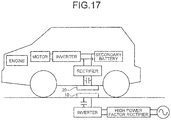
- FIG. 18 As a system for charging a battery of an electric vehicle or a plug-in hybrid car, there has been developing a method that transfers power to the vehicle in contactless manner by using electromagnetic induction, as illustrated in FIG. 18 .
- Such a method transfers power from a primary coil (power transmission coil) 10 installed on the ground to a secondary coil (power reception coil) 20 of the contactless power transfer transformer, installed on a floor of the vehicle.
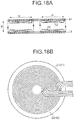
- FIGS. 18A and 18B As the power transmission coil and the power reception coil of the contactless power transfer transformer used in this system, there is disclosed a configuration in which a winding wire (electric wire) is wound in a flattened circle and provided on one face of a flat plate ferrite magnetic core 21, 31, as illustrated in FIGS. 18A and 18B .
- a winding wire electric wire
- FIGS. 18A and 18B Such a coil is referred to as "one-side wound coil” since the winding wires 22, 23 are wound only at one side of the ferrite magnetic cores 21, 31.
- FIG. 18A is a cross sectional view of the power transmission coil and the power reception coil
- FIG. 18B is a plan view of the power transmission coil and the power reception coil.
- the power transfer efficiency of the contactless power transfer transformer that uses the one-side wound coil largely decreases when a vehicle is stopped at a position different from a vehicle stop position and the power transmission coil and the power reception coil do not oppose each other, or when a gap g between the power transmission coil and the power reception coil changes.
- a gap g between the power transmission coil and the power reception coil changes.
- JP 2010 172084 A there is disclosed a contactless power transfer transformer with large permissible amount for the positional variation and the gap variation and that can be configured small in size.
- the power transmission coil and the power reception coil are configured by winding the winding wires 62, 64 around the ferrite cores 61, 63.
- Such a coil is referred to as "both-sides wound coil”.
- the "square core" is used as the ferrite cores 61, 63.
- FIG. 19A is a cross sectional view of the power transmission coil and the power reception coil
- FIG. 19B is a plan view of the power transmission coil and the power reception coil.
- a main magnetic flux 67 that circles around the magnetic pole portions of the ferrite cores 61, 63 is generated. Additionally, bypassing leakage magnetic fluxes 68, 69 are generated on the non-opposing sides of the power transmission coil and the power reception coil. If the leakage magnetic fluxes 68, 69 enter an iron plate or the like of the floor of the vehicle, induced current flows through the iron plate and the iron plate is heated, thereby the power transfer efficiency decreases.
- the core portion around which the coil is wound includes a plurality of separate magnetic members (41) arranged with a spacing therebetween and in parallel with each other.
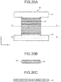
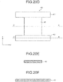
- FIGS. 20A to 20F in order to further decrease a size and weight of the both-sides wound coil, there is disclosed a power transmission coil and a power reception coil as illustrated in FIGS. 20A to 20F .
- a ferrite core is configured in H-shape, parts arranged at both ends of the H-shape and being parallel to each other are provided as magnetic pole portions 41, 42, and a winding wire 50 is wound around a part 43 (the part connects between the magnetic pole portions) corresponding to a horizontal pole of the H-shape.
- FIG. 20A is a state in which the winding wire 50 is wound around the ferrite core 40, and FIG.
- FIG. 20D is a state in which the winding wire 50 is not wound around the ferrite core 40.
- FIG. 20B is a cross sectional view taken along a line A-A of FIG. 20A
- FIG. 20C is a cross sectional view taken along a line B-B of FIG. 20A
- FIG. 20E is a cross sectional view taken along a line A-A of FIG. 20D
- FIG. 20F is a cross sectional view taken along a line B-B of FIG. 20D .
- the power transmission coil and the power reception coil each configured by a both-sides wound coil by using this H-shape core are arranged to oppose each other with a spacing therebetween at a normal gap length of 70 mm and the power transfer of 3 kW is performed.
- the following power transfer properties are obtained.
- the efficiency of the transformer is 95 %
- the permissible amount of positional variation in the left and right direction (y-direction in FIG. 20A ) is ⁇ 150 mm
- the permissible amount of positional variation in the front and back direction (x-direction in FIG. 20A ) is ⁇ 60 mm
- the efficiency at which the normal gap length is increased to 100 mm is 92 %.
- JP 2010 172084 A relates to a contactless power transfer transformer.
- WO 2011/030531 A1 relates to a high power inductance device, with a ferrite core (10)separated into a plurality of separate magnetic members, arranged with a spacing therebetween and in parallel with each others.
- Heat conducting metal plates (12) or Al or Cu are alternately arranged with respect to the separate magnetic members on a plane formed by the separate magnetic members so as to be in contact with the separate magnetic members. Heat generated by the separate magnetic members is guided to the outside of the core through the metal plates, and is dissipated to a heat dissipation structure (18).
- a current at a frequency of approximately between 10 kHz to 200 kHz flows through the power transmission coil.
- a magnetic flux of high-frequency wave is generated. Therefore, at a core part of the power transmission coil and the power reception coil through which the magnetic flux flows, a temperature increases due to iron loss.
- a size of the both-sides wound coil can be decreased; however, a heat capacity decreases therewith.
- the temperature tends to increase due to the iron loss of the core part or due to the copper loss of the winding wire. Therefore, in order to obtain a both-sides wound coil capable of transferring large electric power, the heat dissipation countermeasure is required.
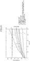
- FIG. 21 illustrates temperature raise test results measured in terms of a relationship between a power transfer time and a temperature of each portion of a power transmission coil and a power reception coil.
- the power transmission coil and the power reception coil are configured by a both-sides wound coil for 10 kW and having H-shape core.
- the temperatures of the primary core, the primary coil, and the primary aluminum plate (corresponding to an electromagnetic shielding metal plate 65, which is an aluminum plate for magnetic shielding, illustrated in FIG. 19 ) of the power transmission coil, temperatures of the secondary core, the secondary coil, and the secondary aluminum plate (corresponding to an electromagnetic shielding metal plate 66, which is an aluminum plate for magnetic shielding, illustrated in FIG. 19 ) of the power reception coil, the room temperature, and the power transfer efficiency are measured over 50 minutes.
- the core of the power reception coil reaches to a temperature of greater than or equal to 110 °C after 50 minutes from the beginning of the power transferring.
- the winding wire is present on a surface of the ferrite core. Therefore, the heat generated by the winding wire of the both-sides wound coil can be dissipated via a casing for containing the coil.
- a portion of the casing is formed of a material having high heat conductivity (such as an aluminum material).
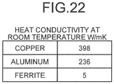
- the ferrite core has a heat conductivity lower than aluminum and copper and further because the ferrite core is wound by the winding wire, the heat dissipation is difficult.
- the heat generated by the core can directly be dissipated from a side at which the ferrite core is not arranged because the winding wire is arranged only on one side of the ferrite core. Further, such a one-side wound coil has a size and a heat capacity larger than that of the both-sides wound coil. Therefore, the heat dissipation countermeasure is not of a large issue.
- an object of the present invention is to provide a contactless power transfer transformer that can effectively dissipate heat of a magnetic (e.g. ferrite) core part, which is covered by a winding wire, of a both-sides wound coil.
- a magnetic e.g. ferrite
- a heat dissipation characteristic of a both-sides wound coil can be improved, and there can be provided a contactless power transfer transformer which uses a both-sides wound coil, is small in size, and is capable of performing first charge.
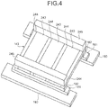
- FIG. 1 schematically illustrates a configuration of a contactless power transfer transformer according to an example forming not part of the present invention.
- FIGS. 2 , 3 , and 4 schematically illustrates a configuration on the way to a configuration of FIG. 1 .
- the contactless power transfer transformer includes a both-sides wound coil in which a winding wire (electric wire) 150 is wound around an inter-magnetic-pole core portion configuring a portion of an H-shape core.
- the winding wire 150 is wound around a winding zone 144 of an inter-magnetic-pole core portion 143, and is not wound around end portions of the inter-magnetic-pole core portion 143 away from the winding zone 144.
- the inter-magnetic-pole core portion 143 is configured by: a plurality of separate magnetic members 243 (ferrite is used in the contactless power transfer transformer as a magnetic body, thereby the separate magnetic member is referred to as a separate ferrite member in the following) that are arranged with a spacing therebetween and in parallel with each other; and a plurality of heat conductors 244 alternately arranged with respect to the separate ferrite members 243 so as to be in contact with a side face of the separate ferrite member 243 arranged at the end and to be in contact with both side faces of the adjacent separate ferrite members 243. Then, the separate ferrite members 243 and the heat conductors 244 are combined together into one flat plate.
- a width of the heat conductor 244 is set to be approximately 1/5 of a width of the separate ferrite member 243.
- the separate ferrite members 243 function as a winding wire core of the H-shape core.
- the heat conductors 244 are formed of a material with high heat conductivity such as an aluminum material. The heat conductors 244 realize a function to guide heat generated at the separate ferrite members 243 at the time of power transferring to an end portion side of the inter-magnetic-pole core portion 143 away from the winding zone.
- both end portions of the inter-magnetic-pole core portion 143 located away from the winding zone 144 are connected to ferrite magnetic pole members 180 via lower layer ferrite plates 181, 182, respectively.
- the ferrite magnetic pole members 180 configure the magnetic pole portions, respectively.
- the length of each of the ferrite magnetic pole members 180 is set to be longer than a width of the inter-magnetic-pole core portion 143 connected to the ferrite magnetic pole members 180 via the lower layer ferrite plates 181, 182.
- the inter-magnetic-pole core portion 143 is connected to a middle portion of each of the ferrite magnetic pole members 180.
- the H-shape core is formed by: two ferrite magnetic pole members 180 that are in parallel with each other; and the inter-magnetic-pole core portion 143 that connects between the two ferrite magnetic pole members 180.
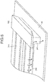
- FIG. 5A is a plan view illustrating a configuration of the both-sides wound coil
- FIG. 5B is a side view of when the both-sides wound coils of FIGS. 5A are arranged opposite each other.
- FIG. 5C illustrates a magnetic gap length G2 and a distance G1 between the winding wires of when the both-sides wound coils are arranged opposite each other.
- the "legs” configured by the lower layer ferrite plates 181, 182 are attached to the ferrite magnetic pole members 180 of the magnetic pole portions. Consequently, it becomes possible to shorten the magnetic gap length G2 to a length equal to or less than the distance G1 between the winding wires.
- the magnetic gap length is shortened, the coupling coefficient between the coils increases, and the power transfer efficiency and the maximum power transfer power increase.
- a heat conductor connecting portions 245 that are closely connected to the heat conductors 244 are arranged at one of the faces of the inter-magnetic-pole core portion 143 opposing other one of the faces at which the ferrite magnetic pole members 180 are connected via the lower layer ferrite plates 181, 182 and at the both end portions of the inter-magnetic-pole core portion 143 away from the winding zone 144.
- the heat conductor connecting portions 245 has a role in guiding the heat transferred from the heat conductors 244 to the outside of the contactless power transfer transformer.
- the heat conductor connecting portions 245 are connected to an electromagnetic shielding metal plate (corresponding to the electromagnetic shielding metal plates 65, 66 of FIG.
- FIG. 6 schematically illustrates the flow of heat communicated to the electromagnetic shielding metal plate 65 via the heat conductor connecting portion 245 from the heat conductors 244.
- the inter-magnetic-pole core portion 143 is configured by alternately arranging the separate ferrite members 243 and the heat conductors 244 with respect to each other on the same plain and in parallel with each other.
- the reasons why the inter-magnetic-pole core portion 143 of such a configuration is employed is because of the following.
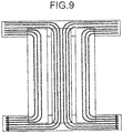
- FIG. 7 illustrates a result of analysis of the flow of the magnetic fluxes of the both-sides wound coil having the H-shape core by using an electromagnetic field analyzing software.
- FIG. 8 illustrates a result of analysis on the leakage magnetic fluxes of the both-sides wound coils each having the H-shape core and opposing each other.
- Conductivity of metal is high. Therefore, if the magnetic flux flowing through the core or the magnetic flux leaking out from the core is shielded by metal, eddy current is generated and the power transfer efficiency is thereby decreased.
- the power transfer efficiency decreases. This is because there exists a leakage magnetic flux from the ferrite member of the inter-magnetic-pole core portion toward directly thereabove as appearing in a part surrounded by a circle Q of FIG. 8 , and because the metal plate shields such a leakage magnetic flux.
- the metal (the heat conductors 244 of the present embodiment) arranged in the spacing does not shield the leakage magnetic flux.
- parallel magnetic fluxes flows from one of the magnetic pole members to other one of the magnetic pole members through the ferrite plates.
- the heat conductors 244 are arranged on the same plane as the separate ferrite members 243 and in parallel to the separate ferrite members 243, so that the heat conductors 244 does not block the magnetic flux flowing through the separate ferrite members 243 or the magnetic flux leaking out from the separate ferrite members 243.
- the heat conductor connecting portion 245 arranged on one of the faces of the inter-magnetic-pole core portion 143 opposing other one of the faces at which the ferrite magnetic pole member 180 is connected does not block the magnetic flux flowing through the separate ferrite members 243 or the leakage magnetic flux. This is because, the magnetic flux flows toward the ferrite magnetic pole member 180.
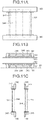
- FIG. 10 illustrates the contactless power transfer transformer used for the measurement and in a state in which the winding wire and the electromagnetic shielding metal plate are removed.
- FIG. 11A illustrates a plan view of the contactless power transfer transformer above the electromagnetic shielding metal plate 65
- FIG. 11B illustrates a side view of the contactless power transfer transformers opposing each other, when viewed from an angle of the ferrite magnetic pole member 180.
- FIG. 11C illustrates a side view of the contactless power transfer transformer opposing each other, when viewed from a different angle.
- FIG. 11A illustrates a state in which the inter-magnetic-pole core portion is housed in the winding frame 151.
- the winding frame 151 defines the wound region 144 (see FIG.
- FIGS. 11A to 11C the ferrite magnetic pole member 180, the separate magnetic member 243, the heat conductor 244, the heat conductor connecting portion 254, and/or the like, are also illustrated.
- FIG. 12 is a temperature raise test result of when the present embodiment is applied.
- FIG. 12 illustrates a temperature change a of the primary core of the power transmission coil, a temperature change b of the primary coil of the power transmission coil, a temperature change e of the aluminum plate (electromagnetic shielding metal plate) for the primary side shielding of the power transmission coil, a temperature change c of the secondary core of the power reception coil, a temperature change d of the secondary coil of the power reception coil, and a temperature change f of the aluminum plate (electromagnetic shielding plate) for secondary side shielding, room temperature g, and power transfer efficiency h, measured over 150 minutes.
- the secondary coil d reaches the temperature of 100 °C after 150 minutes since the beginning of the power transferring. In view of the temperature changes of FIG. 12 , each temperature seems to be nearly at the saturation.
- the power transfer efficiency soon after the start of the power transferring is 94.0 %, and increases to 94.6 % after one hour.
- the temperature of the secondary core reaches 110 °C only within 50 minutes.
- the maximum temperature is approximately 100°C even after 150 minutes, which is three times the aforementioned time period.
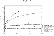
- FIG. 13 illustrates a comparison between the temperature change c' of the secondary core recited in FIG. 21 and the temperature change c of the secondary core recited in FIG. 12 . Further, FIG. 13 illustrates a comparison between the change g' in room temperature recited in FIG. 21 and the change g in room temperature recited in FIG. 12 .
- FIG. 14 illustrates comparison of constants among various contactless power transfer transformer.
- the constants includes: constants (aluminum present) of a contactless power transfer transformer in which an aluminum material is used for the heat conductors 244 and the separate ferrite members 243 and the heat conductors 244 are alternately arranged for the inter-magnetic-pole core portion 143; constants (aluminum absent) of a contactless power transfer transformer in which only the separate ferrite members 243 are arranged with a spacing therebetween for the inter-magnetic-pole core portion 143; and constants (before countermeasure) of a contactless power transfer transformer in which the inter-magnetic-pole core portion 143 of the core is configured by a conventional ferrite member.
- the heat conductors 244 alternately arranged with respect to the separate ferrite members 243 in the inter-magnetic-pole core portion 143 of the both-sides wound coil forms a conducting loop L illustrated by a dotted line (traveling through the heat conductor 244 to one heat conductor connecting portion 245 to the adjacent heat conductor 244 to other one heat conductor connecting portion 245) in FIG. 15A . If there exists a magnetic flux which penetrates through the conducting loop L, a current flowing through the conducting loop L is generated and the power transfer efficiency might be decreased due to the copper loss.
- the heat conductors 244 of a contactless power transfer transformer in accordance with the present invention are divided into half at the middle between the two heat conductor connecting portions 245, as illustrated in FIG. 15B .
- Each of the two divided heat conductors 244 is connected to one of the heat conductor connecting portions 245, thereby the heat dissipating performance does not decrease.
- heat conductors 244 can be formed of copper and the like having high heat conductivity.
- the heat conductors 244 can have a tube structure having a cross section of a square shape in order to increase cooling performance by circulating gas or liquid within the tube structure. Further, the heat conductors 244 can have a heat pipe structure. In this case, circulating liquid absorbs heat at a high temperature portion and is thereby evaporated, releases the heat at a low temperature portion and is thereby liquefied, and the operations are repeated. Accordingly, efficiency in heat transferring from the high temperature portion to the low temperature portion increases.
- a heat dissipating fin or an air supply fan can be provided so as to cool the electromagnetic shielding metal plates 65, 66.
- the both-sides wound coil has the H-shape core is explained above.
- the both-sides wound coil may have a square shape. In such a case, a configuration of the both-sides wound coil can be simplified.
- ferrite is used for the core.
- other magnetic bodies such as an amorphous magnetic body, with less loss at the frequency used for the contactless power transferring can be used for a portion or for the entire core.
- a contactless power transfer transformer as defined in present claim 1 including a both-sides wound coil between two magnetic pole portions.
- the both-sides wound coil includes: an inter-magnetic-pole core portion including a winding region covered by a winding wire; and a winding wire wound around the winding region of the inter-magnetic-pole core portion.
- the inter-magnetic-pole portion includes a plurality of separate magnetic members (magnetic bodies of the inter-magnetic-pole core portion) and heat conductors. Each of the separate magnetic members is connected to magnetic bodies (magnetic magnetic-pole members) of the two magnetic pole portions, and arranged with a spacing therebetween and in parallel with each other.
- the heat conductors are alternately arranged with respect to the separate magnetic members so as to be in contact with the separate magnetic members within a flat face formed by the separate magnetic members.
- the heat generated at the separate magnetic members is taken out to the outside of the winding region of the inter-magnetic-pole core portion through the heat conductors, and dissipated.
- the generated heat of the separate magnetic members covered by the winding wire is dissipated to the outside through the heat conductors.
- the heat conductors or the conducting loop configured by the heat conductors crosses the magnetic field lines traveling through the separate magnetic members or the magnetic field lines leaking to the outside from the separate magnetic members, the eddy current flows though the heat conductors and the eddy current loss is caused. Accordingly, the power transfer efficiency is decreased. Therefore, the heat conductors and the separate magnetic members are arranged on the same plane and in parallel with each other so that the heat conductors or the conducting loop configuring the heat conductors do not cross the magnetic field lines.
- heat conductor connecting portions that adhere to the heat conductors are arranged at both end portions of the inter-magnetic-pole core portion away from the winding region. Then, the heat taken out through the heat conductors is dissipated via the heat conductor connecting portions. That is to say, the generated heat of the separate magnetic members covered by the winding wire is dissipated to the outside via the heat conductors and the heat conductor connecting portions.
- each of the two magnetic pole portions is configured by a magnetic magnetic-pole portion having a length longer than a width of the inter-magnetic-pole core portion connected to the magnetic pole portions. Then, both end portions of the inter-magnetic-pole core portion on one of the faces thereof and away from the winding region are connected to a middle position of the magnetic magnetic-pole members in the elongated direction thereof, respectively. Further, at the both end portions of the inter-magnetic-pole core portion on other one of the faces thereof and away from the winding region, the heat conductor connecting portions adhered to the heat conductors are arranged, respectively. Accordingly, the heat taken out through the heat conductors is dissipated via the heat conductor connecting portions.
- the length of the magnetic magnetic-pole member is set to be longer than the contact width of the inter-magnetic pole core portion so that the core member has the H-shape.
- the heat conductor connecting portions which adhere to the heat conductors are arranged on a face opposite the face of the inter-magnetic-pole core portion connected to the magnetic magnetic-pole member.
- the heat conductor connecting portions are connected to the electromagnetic shielding metal plate installed on a non-opposing face side with respect to a corresponding coil. Therefore, the generated heat of the inter-magnetic-pole core portion covered by the winding wire is guided to the heat conductors that are in contact with the separate magnetic members, to the heat conductor connecting portions, and to the electromagnetic shielding metal plate, and is dissipated.
- the heat conductors are divided into half at a middle position between the two heat conductor connecting portions arranged at both end portions away from the winding region, respectively.
- the heat conductors can be configured by rod-shape bodies of aluminum or copper.
- the heat conductivity of the aluminum or the copper is 50 to 80 times that of the ferrite. Therefore, the heat generated at the separate magnetic members can effectively be taken out.
- the heat conductors may have the pipe structure so that gas or liquid flows therethrough.
- the heat dissipating effect can be increased by making the gas or the liquid, which has high heat conductivity, flowing within the pipe structure.
- a heat pipe may be used for the heat conductor.
- the heat pipe can efficiently move the heat from a high temperature portion to a low temperature portion by phenomenon in which liquid is evaporated at the high temperature portion and the vapor is liquefied at the low temperature portion. Therefore, heat dissipation can be performed efficiently.
- a heat dissipating fin or an air supply fan can be provided to cool the electromagnetic shielding metal plate.
- the magnetic pole portion or the magnetic body of the inter-magnetic-pole core portion can be formed by ferrite. Further, a portion of the magnetic pole portion or the magnetic body of the inter-magnetic-pole core portion can be formed by an amorphous core. Further, the rated power of a transformer of the contactless power transfer transformer can be greater than or equal to 10 kW.
- the contactless power transfer transformer of the present embodiment has high heat dissipation characteristic. Therefore, the contactless power transfer transformer is small and can transfer large power of greater than or equal to 10 kW of the rated power. Consequently, the contactless power transfer transformer can be widely used for contactless power transfer of various moving bodies such as an electric vehicle or a plug-in hybrid car.
Landscapes
- Engineering & Computer Science (AREA)
- Power Engineering (AREA)
- Transportation (AREA)
- Mechanical Engineering (AREA)
- Chemical & Material Sciences (AREA)
- Composite Materials (AREA)
- Electric Propulsion And Braking For Vehicles (AREA)
- Current-Collector Devices For Electrically Propelled Vehicles (AREA)
- Coils Of Transformers For General Uses (AREA)
Claims (10)
- Kontaktloser Leistungsübertragungstransformator mit:einer beidseitig gewickelten Spule, die einen Intermagnetpolkernabschnitt (143) zwischen zwei Magnetpolabschnitten (180-182) enthält,einem Wicklungsdraht (150) von der Spule um einen Wicklungsbereich und ist auf beiden Seiten des Intermagnetpolkernabschnitts gewickelt, wobeider Intermagnetpolkernabschnitt (143) enthält:eine Vielzahl von separaten magnetischen Elementen (243), die jeden der zwei Magnetpolabschnitte verbindet, und mit einer Beabstandung dazwischen und parallel zueinander angeordnet sind; undWärmeleiter (244), die abwechselnd in Bezug auf die separaten magnetischen Elemente in einer von den separaten magnetischen Elementen gebildeten Ebene angeordnet sind, um mit den separaten magnetischen Elementen in Kontakt zu sein,Wärme, die von den separaten magnetischen Elementen erzeugt wird, wird durch die Wärmeleiter nach Außerhalb des Wicklungsbereichs des Intermagnetpolkernabschnitts geführt, und abgeleitet,Wärmeleiterverbindungsabschnitte (245) des Transformators, die an den Wärmeleitern haften, sind an beiden Endabschnitten des Intermagnetpolkernabschnitts angeordnet, die entfernt vom Wicklungsbereich angeordnet sind,die Wärme, die durch den Wärmeleiter geführt wird, wird durch die Wärmeleiterverbindungsabschnitte abgeleitet, unddie Wärmeleiter (244) sind an einer mittigen bzw. mittleren Position zwischen den Wärmeleiterverbindungsabschnitten, die an den beiden Endabschnitten entfernt vom Wicklungsbereich angeordnet sind, halbiert.
- Kontaktloser Leistungsübertragungstransformator gemäß Anspruch 1, wobei
die zwei Magnetpolabschnitte jeweils so konfiguriert sind, dass ein magnetisches Magnetpolelement, das länger ist als eine Breite des Intermagnetpolkernabschnitts (143), mit den Magnetpolabschnitten (180-182) verbunden ist,
jeder der beiden Endabschnitte auf einer der Flächen der Intermagnetpolkernabschnitte und entfernt vom Wicklungsbereich in einer mittigen bzw. mittleren Position in longitudinaler Richtung eines jeden magnetischen Magnetelements angeordnet ist,
jedes der separaten magnetischen Elemente (243) mit zwei magnetischen Magnetpolelementen verbunden ist,
jeder der Wärmeleiterverbindungsabschnitte an beiden Endabschnitten auf einer anderen als der Flächen der Intermagnetpolkernabschnitte und entfernt vom Wicklungsbereich angeordnet ist, und
die Wärme, die durch die Wärmeleiter geführt wird, wird über die Wärmeleiterverbindungsabschnitte abgeleitet. - Kontaktloser Leistungsübertragungstransformator gemäß Anspruch 1 oder 2, wobei
die Wärmeleiterverbindungsabschnitte mit einer elektromagnetischen Abschirmmetallplatte verbunden sind, die an einer nicht der Spule des Transformators gegenüberliegenden Seite vorgesehen ist. - Kontaktloser Leistungsübertragungstransformator gemäß einem der Ansprüche 1 bis 3, wobei
die Wärmeleiter stabförmige Körper aus Aluminium oder Kupfer sind. - Kontaktloser Leistungsübertragungstransformator gemäß einem der Ansprüche 1 bis 3, wobei
die Wärmeleiter (244) eine Rohstruktur aufweisen, und
Gas oder Flüssigkeit durch die Rohrstruktur strömt. - Kontaktloser Leistungsübertragungstransformator gemäß Anspruch 5, wobei
die Rohrstruktur ein Abschnitt eines Wärmerohrs ist. - Kontaktloser Leistungsübertragungstransformator gemäß Anspruch 3, ferner mit
einem Wärmeableitungsseitenleitwerk oder einem Luftversorgungsseitenleitwerk, das die elektromagnetische Abschirmmetallplatte kühlt. - Kontaktloser Leistungsübertragungstransformator gemäß einem der Ansprüche 1 bis 7, wobei
ein magnetischer Körper eines jeden der Magnetpolabschnitte und der Intermagnetpolkernabschnitte Ferrit ist. - Kontaktloser Leistungsübertragungstransformator gemäß einem der Ansprüche 1 bis 7, wobei
ein amorpher Kern für einen Abschnitt vom magnetischen Körper des Magnetpolabschnitts und des Intermagnetpolkernabschnitts verwendet wird. - Kontaktloser Leistungsübertragungstransformator gemäß einem der Ansprüche 1 bis 9, wobei
ein Nennstrom bzw. Benennungsstrom des Transformators größer oder gleich 10 kW ist.
Applications Claiming Priority (2)
| Application Number | Priority Date | Filing Date | Title |
|---|---|---|---|
| JP2012128459 | 2012-06-05 | ||
| PCT/JP2013/065572 WO2013183665A1 (ja) | 2012-06-05 | 2013-06-05 | 非接触給電トランス |
Publications (3)
| Publication Number | Publication Date |
|---|---|
| EP2858079A1 EP2858079A1 (de) | 2015-04-08 |
| EP2858079A4 EP2858079A4 (de) | 2016-02-24 |
| EP2858079B1 true EP2858079B1 (de) | 2017-11-15 |
Family
ID=49712054
Family Applications (1)
| Application Number | Title | Priority Date | Filing Date |
|---|---|---|---|
| EP13800225.8A Not-in-force EP2858079B1 (de) | 2012-06-05 | 2013-06-05 | Kontaktloser leistungsübertragungstransformator |
Country Status (5)
| Country | Link |
|---|---|
| US (1) | US9406429B2 (de) |
| EP (1) | EP2858079B1 (de) |
| JP (2) | JP6147741B2 (de) |
| CN (1) | CN104335303B (de) |
| WO (1) | WO2013183665A1 (de) |
Families Citing this family (18)
| Publication number | Priority date | Publication date | Assignee | Title |
|---|---|---|---|---|
| EP3131174B1 (de) * | 2014-04-08 | 2018-01-31 | Nissan Motor Co., Ltd | Kontaktlose stromversorgungsspule |
| WO2015155834A1 (ja) * | 2014-04-08 | 2015-10-15 | 日産自動車株式会社 | 非接触給電用コイル |
| WO2015155836A1 (ja) * | 2014-04-08 | 2015-10-15 | 日産自動車株式会社 | 非接触給電用コイル |
| GB2529630A (en) * | 2014-08-26 | 2016-03-02 | Bombardier Transp Gmbh | A receiving device for receiving a magnetic field and for producing electric energy by magnetic induction, in particular for use by a vehicle |
| JP6476721B2 (ja) * | 2014-10-10 | 2019-03-06 | 株式会社Ihi | 受電コイル装置および非接触給電システム |
| KR101826495B1 (ko) * | 2015-04-08 | 2018-02-06 | 닛산 지도우샤 가부시키가이샤 | 비접촉 전력 전송용 코일 유닛 |
| DE102015006307B4 (de) * | 2015-05-16 | 2021-03-18 | Audi Ag | Ladevorrichtung zum induktiven Laden eines elektrischen Energiespeichers eines Kraftfahrzeugs und Verfahren zum Betreiben einer Ladevorrichtung |
| CN105405622B (zh) * | 2015-12-31 | 2017-10-03 | 浙江大学 | 一种用于电动汽车无线充电的松散耦合变压器装置 |
| JP6276349B1 (ja) * | 2016-08-30 | 2018-02-07 | 国立大学法人埼玉大学 | 非接触給電装置及び非接触給電装置用電力伝送コイルユニット |
| DE102017206988A1 (de) | 2017-04-26 | 2018-10-31 | Mahle Lnternational Gmbh | Akkumulatoranordnung |
| DE102017207266A1 (de) | 2017-04-28 | 2018-10-31 | Mahle International Gmbh | Induktionsladevorrichtung |
| JP7117540B2 (ja) * | 2018-07-31 | 2022-08-15 | パナソニックIpマネジメント株式会社 | 受電装置および水中給電システム |
| EP3846186A4 (de) | 2018-08-30 | 2022-06-15 | Dai Nippon Printing Co., Ltd. | Leistungstransfervorrichtung, leistungsübertragungsvorrichtung, leistungsempfangsvorrichtung und leistungstransfersystem |
| CN109878360B (zh) * | 2019-03-13 | 2021-06-29 | 上海蔚来汽车有限公司 | 散热控制方法、装置、充电车以及计算机可读存储介质 |
| DE102019209141A1 (de) | 2019-06-25 | 2020-12-31 | Mahle International Gmbh | Verfahren zur Herstellung einer induktiven Ladeeinrichtung |
| AU2020343587B2 (en) | 2019-09-03 | 2023-12-14 | Nippon Steel Corporation | Wound core |
| KR102755493B1 (ko) * | 2019-11-20 | 2025-01-17 | 에스케이씨 주식회사 | 무선충전 패드, 무선충전 장치, 및 이를 포함하는 전기 자동차 |
| DE102022213359A1 (de) * | 2022-12-09 | 2024-06-20 | Mahle International Gmbh | Induktionsladevorrichtung |
Family Cites Families (22)
| Publication number | Priority date | Publication date | Assignee | Title |
|---|---|---|---|---|
| JPS4718012U (de) * | 1971-03-30 | 1972-10-31 | ||
| JPS59125819U (ja) * | 1983-02-09 | 1984-08-24 | シャープ株式会社 | トランス装置 |
| JPH02129716U (de) | 1988-04-20 | 1990-10-25 | ||
| JP2589697Y2 (ja) | 1991-06-04 | 1999-02-03 | 富士通株式会社 | トランス実装構造 |
| JPH06225482A (ja) * | 1993-01-26 | 1994-08-12 | Matsushita Electric Works Ltd | 給電装置 |
| JPH10261534A (ja) * | 1997-03-21 | 1998-09-29 | Sumitomo Wiring Syst Ltd | 電気自動車用充電システム |
| JPH11238638A (ja) * | 1998-02-23 | 1999-08-31 | Toyota Autom Loom Works Ltd | 非接触型充電装置 |
| KR100318670B1 (ko) * | 1999-05-27 | 2002-01-04 | 윤종용 | 방열 리브를 가지는 고압 트랜스포머 |
| JP2002203726A (ja) * | 2001-01-05 | 2002-07-19 | Toyota Industries Corp | 磁性コア |
| JP2002343655A (ja) * | 2001-05-18 | 2002-11-29 | Ishikawajima Harima Heavy Ind Co Ltd | 高電圧大電流用磁気結合コネクタ |
| JP2003142327A (ja) * | 2001-10-31 | 2003-05-16 | Furukawa Electric Co Ltd:The | 非接触給電装置 |
| JP2004014773A (ja) | 2002-06-06 | 2004-01-15 | Matsushita Electric Ind Co Ltd | フェライトコアとそのフェライトコアを用いた磁界発生装置、及び磁界発生装置の製造方法 |
| US7295092B2 (en) * | 2002-12-19 | 2007-11-13 | Cooper Technologies Company | Gapped core structure for magnetic components |
| JP4506668B2 (ja) * | 2005-12-27 | 2010-07-21 | トヨタ自動車株式会社 | リアクトルの冷却構造および電気機器ユニット |
| JP4356844B2 (ja) | 2006-10-05 | 2009-11-04 | 昭和飛行機工業株式会社 | 非接触給電装置 |
| JP4605192B2 (ja) * | 2007-07-20 | 2011-01-05 | セイコーエプソン株式会社 | コイルユニット及び電子機器 |
| US8947186B2 (en) * | 2008-09-27 | 2015-02-03 | Witricity Corporation | Wireless energy transfer resonator thermal management |
| JP5467569B2 (ja) * | 2009-01-21 | 2014-04-09 | 国立大学法人埼玉大学 | 非接触給電装置 |
| JP5240786B2 (ja) * | 2009-08-25 | 2013-07-17 | 国立大学法人埼玉大学 | 非接触給電装置 |
| JP5601661B2 (ja) * | 2009-09-11 | 2014-10-08 | Fdk株式会社 | 大電力用インダクタンス装置 |
| EP2617120B1 (de) * | 2010-09-14 | 2017-01-18 | WiTricity Corporation | Drahtloses energieverteilungssystem |
| JP5562804B2 (ja) * | 2010-11-02 | 2014-07-30 | 昭和飛行機工業株式会社 | インダクタンス可変の非接触給電装置 |
-
2013
- 2013-06-05 US US14/405,022 patent/US9406429B2/en not_active Expired - Fee Related
- 2013-06-05 JP JP2014520025A patent/JP6147741B2/ja active Active
- 2013-06-05 WO PCT/JP2013/065572 patent/WO2013183665A1/ja not_active Ceased
- 2013-06-05 CN CN201380029282.1A patent/CN104335303B/zh not_active Expired - Fee Related
- 2013-06-05 EP EP13800225.8A patent/EP2858079B1/de not_active Not-in-force
-
2016
- 2016-12-13 JP JP2016241691A patent/JP6400663B2/ja active Active
Non-Patent Citations (1)
| Title |
|---|
| None * |
Also Published As
| Publication number | Publication date |
|---|---|
| JP6400663B2 (ja) | 2018-10-03 |
| HK1206141A1 (en) | 2015-12-31 |
| EP2858079A4 (de) | 2016-02-24 |
| EP2858079A1 (de) | 2015-04-08 |
| US9406429B2 (en) | 2016-08-02 |
| JP2017103461A (ja) | 2017-06-08 |
| JPWO2013183665A1 (ja) | 2016-02-01 |
| CN104335303B (zh) | 2017-10-24 |
| CN104335303A (zh) | 2015-02-04 |
| JP6147741B2 (ja) | 2017-06-14 |
| US20150137925A1 (en) | 2015-05-21 |
| WO2013183665A1 (ja) | 2013-12-12 |
Similar Documents
| Publication | Publication Date | Title |
|---|---|---|
| EP2858079B1 (de) | Kontaktloser leistungsübertragungstransformator | |
| US10784035B2 (en) | Coil device and coil system | |
| JP5923916B2 (ja) | 非接触給電装置 | |
| US9793045B2 (en) | Contactless power transfer transformer for moving body | |
| CN105405622B (zh) | 一种用于电动汽车无线充电的松散耦合变压器装置 | |
| JP6665454B2 (ja) | コイル装置及びコイルシステム | |
| CN104953719B (zh) | 线圈单元以及无线电力传输装置 | |
| CN104952605B (zh) | 线圈单元以及无线电力传输装置 | |
| US20140368059A1 (en) | Transformer, electronic apparatus, and method for controlling transformer | |
| JP2013055229A (ja) | 非接触給電トランス | |
| WO2014103298A1 (ja) | リアクトル | |
| JP2017045792A (ja) | コイル装置 | |
| JP6179160B2 (ja) | ワイヤレス電力伝送装置 | |
| JP2014053366A (ja) | コイル装置 | |
| JP6111645B2 (ja) | コイル装置及びそれを用いたワイヤレス電力伝送システム | |
| CN109910645B (zh) | 无线充电模组及其加工方法、车辆的无线充电装置 | |
| CN110027418B (zh) | 一种具有最短磁路的无线充电装置 | |
| HK1206141B (en) | Contactless feeding transformer | |
| JP6035155B2 (ja) | 非接触給電トランスのコイル装置 | |
| Boumerdassi et al. | LCC-Compensated Wireless Power Receiver: An Efficient and Lightweight Solution for EVs | |
| RU2699058C1 (ru) | Магнитная система | |
| KR20250009903A (ko) | 절연성이 강화된 무선 충전 패드 및 무선 충전 패드의 제조 방법 | |
| Triviño-Cabrera et al. | Coil Design for Magnetic Resonance Chargers | |
| CN121306752A (zh) | 磁集成变压器以及电源系统 | |
| JP2002353036A (ja) | 電気機器 |
Legal Events
| Date | Code | Title | Description |
|---|---|---|---|
| PUAI | Public reference made under article 153(3) epc to a published international application that has entered the european phase |
Free format text: ORIGINAL CODE: 0009012 |
|
| 17P | Request for examination filed |
Effective date: 20141201 |
|
| AK | Designated contracting states |
Kind code of ref document: A1 Designated state(s): AL AT BE BG CH CY CZ DE DK EE ES FI FR GB GR HR HU IE IS IT LI LT LU LV MC MK MT NL NO PL PT RO RS SE SI SK SM TR |
|
| AX | Request for extension of the european patent |
Extension state: BA ME |
|
| DAX | Request for extension of the european patent (deleted) | ||
| RA4 | Supplementary search report drawn up and despatched (corrected) |
Effective date: 20160121 |
|
| RIC1 | Information provided on ipc code assigned before grant |
Ipc: H01F 27/22 20060101ALI20160115BHEP Ipc: H01F 27/24 20060101ALI20160115BHEP Ipc: H01F 38/14 20060101AFI20160115BHEP Ipc: H01F 3/14 20060101ALI20160115BHEP Ipc: B60L 11/18 20060101ALI20160115BHEP |
|
| 17Q | First examination report despatched |
Effective date: 20161103 |
|
| GRAP | Despatch of communication of intention to grant a patent |
Free format text: ORIGINAL CODE: EPIDOSNIGR1 |
|
| GRAJ | Information related to disapproval of communication of intention to grant by the applicant or resumption of examination proceedings by the epo deleted |
Free format text: ORIGINAL CODE: EPIDOSDIGR1 |
|
| INTG | Intention to grant announced |
Effective date: 20170410 |
|
| GRAP | Despatch of communication of intention to grant a patent |
Free format text: ORIGINAL CODE: EPIDOSNIGR1 |
|
| INTC | Intention to grant announced (deleted) | ||
| INTG | Intention to grant announced |
Effective date: 20170523 |
|
| GRAS | Grant fee paid |
Free format text: ORIGINAL CODE: EPIDOSNIGR3 |
|
| GRAA | (expected) grant |
Free format text: ORIGINAL CODE: 0009210 |
|
| AK | Designated contracting states |
Kind code of ref document: B1 Designated state(s): AL AT BE BG CH CY CZ DE DK EE ES FI FR GB GR HR HU IE IS IT LI LT LU LV MC MK MT NL NO PL PT RO RS SE SI SK SM TR |
|
| REG | Reference to a national code |
Ref country code: CH Ref legal event code: EP Ref country code: GB Ref legal event code: FG4D Ref country code: AT Ref legal event code: REF Ref document number: 947024 Country of ref document: AT Kind code of ref document: T Effective date: 20171115 |
|
| REG | Reference to a national code |
Ref country code: IE Ref legal event code: FG4D |
|
| REG | Reference to a national code |
Ref country code: DE Ref legal event code: R096 Ref document number: 602013029557 Country of ref document: DE |
|
| REG | Reference to a national code |
Ref country code: NL Ref legal event code: MP Effective date: 20171115 |
|
| REG | Reference to a national code |
Ref country code: LT Ref legal event code: MG4D |
|
| REG | Reference to a national code |
Ref country code: AT Ref legal event code: MK05 Ref document number: 947024 Country of ref document: AT Kind code of ref document: T Effective date: 20171115 |
|
| PG25 | Lapsed in a contracting state [announced via postgrant information from national office to epo] |
Ref country code: SE Free format text: LAPSE BECAUSE OF FAILURE TO SUBMIT A TRANSLATION OF THE DESCRIPTION OR TO PAY THE FEE WITHIN THE PRESCRIBED TIME-LIMIT Effective date: 20171115 Ref country code: LT Free format text: LAPSE BECAUSE OF FAILURE TO SUBMIT A TRANSLATION OF THE DESCRIPTION OR TO PAY THE FEE WITHIN THE PRESCRIBED TIME-LIMIT Effective date: 20171115 Ref country code: NL Free format text: LAPSE BECAUSE OF FAILURE TO SUBMIT A TRANSLATION OF THE DESCRIPTION OR TO PAY THE FEE WITHIN THE PRESCRIBED TIME-LIMIT Effective date: 20171115 Ref country code: NO Free format text: LAPSE BECAUSE OF FAILURE TO SUBMIT A TRANSLATION OF THE DESCRIPTION OR TO PAY THE FEE WITHIN THE PRESCRIBED TIME-LIMIT Effective date: 20180215 Ref country code: FI Free format text: LAPSE BECAUSE OF FAILURE TO SUBMIT A TRANSLATION OF THE DESCRIPTION OR TO PAY THE FEE WITHIN THE PRESCRIBED TIME-LIMIT Effective date: 20171115 Ref country code: ES Free format text: LAPSE BECAUSE OF FAILURE TO SUBMIT A TRANSLATION OF THE DESCRIPTION OR TO PAY THE FEE WITHIN THE PRESCRIBED TIME-LIMIT Effective date: 20171115 |
|
| PG25 | Lapsed in a contracting state [announced via postgrant information from national office to epo] |
Ref country code: RS Free format text: LAPSE BECAUSE OF FAILURE TO SUBMIT A TRANSLATION OF THE DESCRIPTION OR TO PAY THE FEE WITHIN THE PRESCRIBED TIME-LIMIT Effective date: 20171115 Ref country code: GR Free format text: LAPSE BECAUSE OF FAILURE TO SUBMIT A TRANSLATION OF THE DESCRIPTION OR TO PAY THE FEE WITHIN THE PRESCRIBED TIME-LIMIT Effective date: 20180216 Ref country code: HR Free format text: LAPSE BECAUSE OF FAILURE TO SUBMIT A TRANSLATION OF THE DESCRIPTION OR TO PAY THE FEE WITHIN THE PRESCRIBED TIME-LIMIT Effective date: 20171115 Ref country code: AT Free format text: LAPSE BECAUSE OF FAILURE TO SUBMIT A TRANSLATION OF THE DESCRIPTION OR TO PAY THE FEE WITHIN THE PRESCRIBED TIME-LIMIT Effective date: 20171115 Ref country code: BG Free format text: LAPSE BECAUSE OF FAILURE TO SUBMIT A TRANSLATION OF THE DESCRIPTION OR TO PAY THE FEE WITHIN THE PRESCRIBED TIME-LIMIT Effective date: 20180215 Ref country code: LV Free format text: LAPSE BECAUSE OF FAILURE TO SUBMIT A TRANSLATION OF THE DESCRIPTION OR TO PAY THE FEE WITHIN THE PRESCRIBED TIME-LIMIT Effective date: 20171115 |
|
| REG | Reference to a national code |
Ref country code: FR Ref legal event code: PLFP Year of fee payment: 6 |
|
| PG25 | Lapsed in a contracting state [announced via postgrant information from national office to epo] |
Ref country code: DK Free format text: LAPSE BECAUSE OF FAILURE TO SUBMIT A TRANSLATION OF THE DESCRIPTION OR TO PAY THE FEE WITHIN THE PRESCRIBED TIME-LIMIT Effective date: 20171115 Ref country code: EE Free format text: LAPSE BECAUSE OF FAILURE TO SUBMIT A TRANSLATION OF THE DESCRIPTION OR TO PAY THE FEE WITHIN THE PRESCRIBED TIME-LIMIT Effective date: 20171115 Ref country code: CY Free format text: LAPSE BECAUSE OF FAILURE TO SUBMIT A TRANSLATION OF THE DESCRIPTION OR TO PAY THE FEE WITHIN THE PRESCRIBED TIME-LIMIT Effective date: 20171115 Ref country code: CZ Free format text: LAPSE BECAUSE OF FAILURE TO SUBMIT A TRANSLATION OF THE DESCRIPTION OR TO PAY THE FEE WITHIN THE PRESCRIBED TIME-LIMIT Effective date: 20171115 Ref country code: SK Free format text: LAPSE BECAUSE OF FAILURE TO SUBMIT A TRANSLATION OF THE DESCRIPTION OR TO PAY THE FEE WITHIN THE PRESCRIBED TIME-LIMIT Effective date: 20171115 |
|
| REG | Reference to a national code |
Ref country code: DE Ref legal event code: R097 Ref document number: 602013029557 Country of ref document: DE |
|
| PG25 | Lapsed in a contracting state [announced via postgrant information from national office to epo] |
Ref country code: RO Free format text: LAPSE BECAUSE OF FAILURE TO SUBMIT A TRANSLATION OF THE DESCRIPTION OR TO PAY THE FEE WITHIN THE PRESCRIBED TIME-LIMIT Effective date: 20171115 Ref country code: SM Free format text: LAPSE BECAUSE OF FAILURE TO SUBMIT A TRANSLATION OF THE DESCRIPTION OR TO PAY THE FEE WITHIN THE PRESCRIBED TIME-LIMIT Effective date: 20171115 Ref country code: PL Free format text: LAPSE BECAUSE OF FAILURE TO SUBMIT A TRANSLATION OF THE DESCRIPTION OR TO PAY THE FEE WITHIN THE PRESCRIBED TIME-LIMIT Effective date: 20171115 Ref country code: IT Free format text: LAPSE BECAUSE OF FAILURE TO SUBMIT A TRANSLATION OF THE DESCRIPTION OR TO PAY THE FEE WITHIN THE PRESCRIBED TIME-LIMIT Effective date: 20171115 |
|
| PLBE | No opposition filed within time limit |
Free format text: ORIGINAL CODE: 0009261 |
|
| STAA | Information on the status of an ep patent application or granted ep patent |
Free format text: STATUS: NO OPPOSITION FILED WITHIN TIME LIMIT |
|
| 26N | No opposition filed |
Effective date: 20180817 |
|
| PG25 | Lapsed in a contracting state [announced via postgrant information from national office to epo] |
Ref country code: SI Free format text: LAPSE BECAUSE OF FAILURE TO SUBMIT A TRANSLATION OF THE DESCRIPTION OR TO PAY THE FEE WITHIN THE PRESCRIBED TIME-LIMIT Effective date: 20171115 |
|
| REG | Reference to a national code |
Ref country code: CH Ref legal event code: PL |
|
| REG | Reference to a national code |
Ref country code: BE Ref legal event code: MM Effective date: 20180630 |
|
| REG | Reference to a national code |
Ref country code: IE Ref legal event code: MM4A |
|
| PG25 | Lapsed in a contracting state [announced via postgrant information from national office to epo] |
Ref country code: LU Free format text: LAPSE BECAUSE OF NON-PAYMENT OF DUE FEES Effective date: 20180605 Ref country code: MC Free format text: LAPSE BECAUSE OF FAILURE TO SUBMIT A TRANSLATION OF THE DESCRIPTION OR TO PAY THE FEE WITHIN THE PRESCRIBED TIME-LIMIT Effective date: 20171115 |
|
| PG25 | Lapsed in a contracting state [announced via postgrant information from national office to epo] |
Ref country code: CH Free format text: LAPSE BECAUSE OF NON-PAYMENT OF DUE FEES Effective date: 20180630 Ref country code: LI Free format text: LAPSE BECAUSE OF NON-PAYMENT OF DUE FEES Effective date: 20180630 Ref country code: IE Free format text: LAPSE BECAUSE OF NON-PAYMENT OF DUE FEES Effective date: 20180605 |
|
| PG25 | Lapsed in a contracting state [announced via postgrant information from national office to epo] |
Ref country code: BE Free format text: LAPSE BECAUSE OF NON-PAYMENT OF DUE FEES Effective date: 20180630 |
|
| REG | Reference to a national code |
Ref country code: FR Ref legal event code: PLFP Year of fee payment: 7 |
|
| PGFP | Annual fee paid to national office [announced via postgrant information from national office to epo] |
Ref country code: DE Payment date: 20190321 Year of fee payment: 7 |
|
| PGFP | Annual fee paid to national office [announced via postgrant information from national office to epo] |
Ref country code: FR Payment date: 20190625 Year of fee payment: 7 |
|
| PGFP | Annual fee paid to national office [announced via postgrant information from national office to epo] |
Ref country code: GB Payment date: 20190624 Year of fee payment: 7 |
|
| PG25 | Lapsed in a contracting state [announced via postgrant information from national office to epo] |
Ref country code: MT Free format text: LAPSE BECAUSE OF NON-PAYMENT OF DUE FEES Effective date: 20180605 |
|
| PG25 | Lapsed in a contracting state [announced via postgrant information from national office to epo] |
Ref country code: TR Free format text: LAPSE BECAUSE OF FAILURE TO SUBMIT A TRANSLATION OF THE DESCRIPTION OR TO PAY THE FEE WITHIN THE PRESCRIBED TIME-LIMIT Effective date: 20171115 |
|
| PG25 | Lapsed in a contracting state [announced via postgrant information from national office to epo] |
Ref country code: PT Free format text: LAPSE BECAUSE OF FAILURE TO SUBMIT A TRANSLATION OF THE DESCRIPTION OR TO PAY THE FEE WITHIN THE PRESCRIBED TIME-LIMIT Effective date: 20171115 |
|
| PG25 | Lapsed in a contracting state [announced via postgrant information from national office to epo] |
Ref country code: MK Free format text: LAPSE BECAUSE OF NON-PAYMENT OF DUE FEES Effective date: 20171115 Ref country code: HU Free format text: LAPSE BECAUSE OF FAILURE TO SUBMIT A TRANSLATION OF THE DESCRIPTION OR TO PAY THE FEE WITHIN THE PRESCRIBED TIME-LIMIT; INVALID AB INITIO Effective date: 20130605 |
|
| PG25 | Lapsed in a contracting state [announced via postgrant information from national office to epo] |
Ref country code: AL Free format text: LAPSE BECAUSE OF FAILURE TO SUBMIT A TRANSLATION OF THE DESCRIPTION OR TO PAY THE FEE WITHIN THE PRESCRIBED TIME-LIMIT Effective date: 20171115 Ref country code: IS Free format text: LAPSE BECAUSE OF FAILURE TO SUBMIT A TRANSLATION OF THE DESCRIPTION OR TO PAY THE FEE WITHIN THE PRESCRIBED TIME-LIMIT Effective date: 20180315 |
|
| REG | Reference to a national code |
Ref country code: DE Ref legal event code: R119 Ref document number: 602013029557 Country of ref document: DE |
|
| GBPC | Gb: european patent ceased through non-payment of renewal fee |
Effective date: 20200605 |
|
| PG25 | Lapsed in a contracting state [announced via postgrant information from national office to epo] |
Ref country code: FR Free format text: LAPSE BECAUSE OF NON-PAYMENT OF DUE FEES Effective date: 20200630 Ref country code: GB Free format text: LAPSE BECAUSE OF NON-PAYMENT OF DUE FEES Effective date: 20200605 |
|
| PG25 | Lapsed in a contracting state [announced via postgrant information from national office to epo] |
Ref country code: DE Free format text: LAPSE BECAUSE OF NON-PAYMENT OF DUE FEES Effective date: 20210101 |