EP2857567A1 - Procédé et dispositif de surveillance de la production d'une machine à tricoter - Google Patents
Procédé et dispositif de surveillance de la production d'une machine à tricoter Download PDFInfo
- Publication number
- EP2857567A1 EP2857567A1 EP14183885.4A EP14183885A EP2857567A1 EP 2857567 A1 EP2857567 A1 EP 2857567A1 EP 14183885 A EP14183885 A EP 14183885A EP 2857567 A1 EP2857567 A1 EP 2857567A1
- Authority
- EP
- European Patent Office
- Prior art keywords
- unit
- clock
- clock signal
- knitting
- yarn
- Prior art date
- Legal status (The legal status is an assumption and is not a legal conclusion. Google has not performed a legal analysis and makes no representation as to the accuracy of the status listed.)
- Granted
Links
- 238000009940 knitting Methods 0.000 title claims abstract description 162
- 238000000034 method Methods 0.000 title claims abstract description 22
- 238000004519 manufacturing process Methods 0.000 title claims abstract description 16
- 238000012544 monitoring process Methods 0.000 title claims abstract description 16
- 238000011156 evaluation Methods 0.000 claims abstract description 8
- 238000004804 winding Methods 0.000 claims description 19
- 230000004044 response Effects 0.000 claims description 3
- 238000004891 communication Methods 0.000 description 15
- 238000012806 monitoring device Methods 0.000 description 14
- 230000006870 function Effects 0.000 description 11
- 230000027455 binding Effects 0.000 description 9
- 238000009739 binding Methods 0.000 description 9
- 238000005259 measurement Methods 0.000 description 8
- 238000010586 diagram Methods 0.000 description 4
- 239000004753 textile Substances 0.000 description 4
- 230000001419 dependent effect Effects 0.000 description 3
- 230000003287 optical effect Effects 0.000 description 3
- 238000012545 processing Methods 0.000 description 3
- 230000005540 biological transmission Effects 0.000 description 1
- 239000004020 conductor Substances 0.000 description 1
- 239000004744 fabric Substances 0.000 description 1
- 230000000737 periodic effect Effects 0.000 description 1
- 230000001105 regulatory effect Effects 0.000 description 1
Images


Classifications
-
- D—TEXTILES; PAPER
- D04—BRAIDING; LACE-MAKING; KNITTING; TRIMMINGS; NON-WOVEN FABRICS
- D04B—KNITTING
- D04B15/00—Details of, or auxiliary devices incorporated in, weft knitting machines, restricted to machines of this kind
- D04B15/38—Devices for supplying, feeding, or guiding threads to needles
- D04B15/48—Thread-feeding devices
- D04B15/482—Thread-feeding devices comprising a rotatable or stationary intermediate storage drum from which the thread is axially and intermittently pulled off; Devices which can be switched between positive feed and intermittent feed
- D04B15/484—Yarn braking means acting on the drum
-
- D—TEXTILES; PAPER
- D04—BRAIDING; LACE-MAKING; KNITTING; TRIMMINGS; NON-WOVEN FABRICS
- D04B—KNITTING
- D04B35/00—Details of, or auxiliary devices incorporated in, knitting machines, not otherwise provided for
- D04B35/10—Indicating, warning, or safety devices, e.g. stop motions
- D04B35/12—Indicating, warning, or safety devices, e.g. stop motions responsive to thread consumption
-
- D—TEXTILES; PAPER
- D04—BRAIDING; LACE-MAKING; KNITTING; TRIMMINGS; NON-WOVEN FABRICS
- D04B—KNITTING
- D04B35/00—Details of, or auxiliary devices incorporated in, knitting machines, not otherwise provided for
- D04B35/10—Indicating, warning, or safety devices, e.g. stop motions
- D04B35/14—Indicating, warning, or safety devices, e.g. stop motions responsive to thread breakage
Definitions
- the invention relates to a method and a device for monitoring the production of a knitting machine.
- the control unit polls the sensor devices individually based on a periodic reference signal that is a function of the operating position of the textile machine, according to the data regarding the state of supply of the threads.
- the control unit controls the operation of the textile machine with the data from the sensor devices. It interrupts the operation of the textile machine when a difference occurs between the data obtained from at least one sensor device and the corresponding stored data.
- a production monitoring / adjustment device and a corresponding method for a knitting machine, in particular a circular knitting machine are in the EP 1 370 720 B1 described.
- the apparatus comprises a plurality of knitting systems, a plurality of delivery devices and a computerized unit, the delivery devices being connected to the computerized unit.
- the production monitor / adjuster receives trig signals.
- yarn is delivered to the active knitting systems of a plurality of non-positive delivering delivery devices according to at least two distinct yarn delivery principles.
- the individual yarn quantities are continuously measured by means of sampled actual rotation signals at the delivery devices.
- the individual yarn quantities are compared in the computerized unit with nominal yarn quantities of about a masterpiece and information and / or adjustment measures derived from the comparisons. Tolerances are defined for the comparisons, which are matched in their width to yarn quality and / or yarn path parameters. Exceeding the different tolerance ranges is used to trigger different measures, such as alarm signals, adjustment measures or switching off the knitting machine.
- the individual Yarn quantities are also used to determine a total amount of yarn and / or a yarn weight, being converted or converted into equal units or weight units.
- the knitting machine with its machine control, the production monitoring / adjustment device and the delivery devices are connected via a bus system, e.g. a CAN bus system or a daisy chain linked.
- a bus system e.g. a CAN bus system or a daisy chain linked.
- yarn quantities of a certain size are compared with their target yarn quantities.
- the individual yarn quantities are determined, for example, for knitting paths which correspond to one or more revolutions of the knitting cylinder of the circular knitting machine.
- the EP 2 270 269 B1 describes a method for detecting the stopping of yarn unwinding from a yarn feeder to a downstream machine.
- the yarn feeder has a stationary drum and a sensor, through whose sensor signal one pulse is generated per loop unwound from the drum.
- the machine is stopped when a measured time since the last pulse exceeds a setpoint for the time between two pulses.
- the setpoint is updated in real time depending on the yarn unwinding speed.
- the object of the invention is to improve a method and a device for monitoring the production of a knitting machine.
- it is the task of Invention to allow a quick stop the knitting machine at yarn standstill or yarn breakage with little effort.
- the object is achieved by a method according to claim 1.
- An inventive method relates to the monitoring of the production of a knitting machine and allows in particular with little effort a rapid stopping of the knitting machine in yarn standstill or yarn breakage.
- a knitting machine is designed, for example, as a circular knitting machine or a flat knitting machine.
- a circular knitting machine has several or a plurality of identical or different yarn feeding devices.
- Yarn feeding devices are, for example, positive yarn feeding devices, thread tension controlled yarn feeding devices or storage yarn feeding devices. Thread tension controlled thread feeders and store thread feeders are used when making knitwear with patterns.
- the thread delivery takes place at storage yarn feeding devices in which the thread is withdrawn from, for example, a winding body.
- the yarn delivery takes place, in which the thread tension is regulated and the yarn is delivered accordingly.
- the yarn delivery of the Postiv yarn feeding devices is a feeding of the thread synchronously to the speed of the knitting machine.
- the yarn delivery of at least one yarn feeding device is monitored by a sensor device and a control unit.
- a sensor signal is generated with one measurement pulse per unit length of a yarn delivery path.
- This sensor signal is evaluated by the control unit.
- a stop signal for the knitting machine is generated by the control unit.
- the respective control unit is provided by a clock unit, a clock signal available.
- a clock pulse of the clock signal corresponds to a unit length of a knitting path.
- the length unit of the knitting path is smaller by a factor of at least 2 than the unit length of the yarn feeding path.
- the factor is 3 to 10.
- the sensor signal indicating the yarn delivery path is evaluated by the control unit as a function of the clock signal indicating the knitting path.
- a stop signal for the knitting machine is possibly generated by the control unit.
- the knitting path is defined in the context of the invention in a circular knitting machine as the distance traveled by the outer diameter of the knitting cylinder, on which the knitting needles are. That in one revolution of the knitting cylinder, the knitting path corresponds to the outer circumference of the knitting cylinder.
- the knitting path is defined in a flat knitting machine as the path traveled along the needle bed by the carriage.
- individual measuring pulses are evaluated in response to a specific clock signal, which represents a measure of the knitting path, for monitoring yarn delivery, for example, for yarn breakage.
- the clock signal is selected or generated so that at least 2 clock pulses are available per measuring pulse.
- a certain number of these clock pulses corresponds to a certain length of the knitting path. It is independent of the machine speed of the knitting machine and also of the withdrawal speed of the thread. In operation, a number of clock pulses can be determined simply by counting.
- the length unit of the knitting path is 2 to 8 cm. It is preferably 4 to 6 cm.
- a number of clock pulses of the clock signal are counted by the control unit for evaluating the sensor signal in each case starting with a measurement pulse.
- the number of detected clock pulses is compared with a predetermined number.
- the predetermined number corresponds to the factor given above, which corresponds to the ratio of the unit length of the yarn delivery path to the length unit of the knitting path, or is determined from the factor.
- the predetermined number for a yarn feeding device is selected in one embodiment, depending on the binding, such as mesh, float and handle, the knitted product.
- the predetermined number in the case of binding floats corresponds, for example, to the order of magnitude of the factor Z. For example, in the binding loop, it is reduced to one-third of the factor Z. For example, when changing binding within a product, an average value is chosen.
- a predetermined number plus a safety constant or multiplied by a safety value is selected as a predetermined number as determined.
- a stop signal for the knitting machine is generated by the control unit. Exceeding the given number indicates that the thread is being delivered too slowly or broken.
- the number of clock pulses that trigger a stop signal is constant even if the withdrawal speed of the thread changes by changing the speed of the knitting machine. An additional consideration of the take-off speed is not necessary. This monitoring of the yarn delivery is possible only by using a dependent of the knitting path clock signal.
- the length unit of the yarn delivery path corresponds to a wound from a winding body of the yarn feeding device yarn winding or a part of the unwound Garnwindung.
- the yarn feeding device are designed as a storage yarn feeding device and the winding body as a storage drum.
- the clock unit is provided with a clock signal.
- the clock signal is generated by a clock unit depending on the knitting route of the knitting machine.
- the clock signal is used by the clock unit as the clock signal or the clock signal is generated from the clock signal.
- the clock signal is extracted in one embodiment by the timing unit of the machine controller of the knitting machine or generated from one or more machine signals.
- the clock signal is generated in an alternative embodiment by the clock unit by means of a measurement of the traveled knit path.
- the clock signal is provided by a clock unit designed as a clock unit.
- every N th pulse of the clock signal is used as the clock pulse, where N is an integer number.
- the clock signal of a knitting machine designed as a circular knitting machine is determined by the clock unit as a function of the rotation of a knitting cylinder of the circular knitting machine.
- the clock unit has, for example, a mechanical or electronic measuring unit.
- ⁇ XS is the length unit of the knitting path
- m is the number of pulses m of the clock signal per revolution of the knitting cylinder
- U is the circumference of the knitting cylinder.
- the number m of pulses is determined in one example in an initialization of the monitoring device by the clock unit using the machine control.
- the circumference U and the length unit ⁇ XS of the knitting path are predetermined, for example, by an operator.
- each pulse is used as a clock pulse, i. the clock signal is used as a clock signal.
- the clock signal generator signal is generated from sensor signals by the clock unit designed as a clock unit, wherein the sensor signals are provided by sensor devices of one or more yarn feeding devices.
- measurement pulses of the sensor signals from, for example, 6 to 10 storage yarn feeding devices are interpreted by the clock unit designed as a clock unit as pulses of the clock signal.
- the clock unit designed as a clock unit as pulses of the clock signal.
- Nth for example second, pulse as a clock pulse of the clock signal.
- monitoring device for monitoring the production of a knitting machine, referred to below as monitoring device, according to claim 11 and knitting machine according to claim 20.
- monitoring device for monitoring the production of a knitting machine
- knitting machine according to claim 20.
- a monitoring device comprises at least one yarn feeding device.
- Each yarn feeding device of the monitoring device is associated with a sensor device and a control unit.
- the sensor device is designed to generate a sensor signal as a function of a yarn delivery path, i. from the length of the yarn supplied to the knitting machine.
- the sensor device generates a sensor signal with one measurement pulse per unit length of the yarn delivery path.
- the control unit is designed to evaluate the sensor signal of the sensor device and, if necessary, to generate a stop signal for the knitting machine.
- control unit for evaluating the sensor signal is connected to the sensor device.
- control unit is directly connected to the sensor device or connected to it via a communication line.
- the control unit is integrated in one embodiment in the sensor device. It is integrated into the yarn feeder in an alternative. In an alternative, the control unit is designed as a separate device.
- the monitoring device comprises a clock unit, which is designed to provide the control unit (s) with a clock signal dependent on the knitting path of the knitting machine.
- a clock pulse of the clock signal corresponds to a unit length of a knitting route.
- the length unit of the knitting path is selected so that it is smaller by a factor of at least 2 than the length unit of the yarn delivery path.
- the factor is 3 to 10.
- the control unit evaluates the sensor signal as a function of the clock signal provided.
- the length unit of the knitting path is 2 to 8 cm. It is preferably 4 to 6 cm.
- the clock unit is formed in one embodiment as a control unit for the yarn feeding devices or integrated into a control unit. In an alternative embodiment, the clock unit is formed as a separate unit.
- control unit or units are integrated into the clock unit. That the clock unit comprises the control unit of one, several or all sensor devices.
- control unit is designed in each case to count a number of clock pulses beginning with one measurement pulse and to compare the number of clock pulses with a predetermined number.
- the predetermined number corresponds to the factor mentioned above or is determined from it.
- the control unit is configured to generate a stop signal for the knitting machine when the determined number of clock pulses exceeds the predetermined number.
- the yarn feeding device has a winding body, wherein the length unit corresponds to a wound from the wound body of the yarn feeding device yarn winding or a part of the unwound Garnwindung.
- the yarn feeding device is designed as a storage yarn feeding device and the winding body as a storage drum.
- the sensor device is arranged, for example, at the discharge end of the storage drum. It comprises, for example, an optical sensor which transmits one pulse per passing, i. From the drum withdrawn yarn winding generated.
- the monitoring device comprises a clock unit, which is designed to provide a clock signal which is designed as a signal dependent on the knitting path of the knitting machine.
- the clock unit is configured to use the clock signal as the clock signal or to generate the clock signal from the clock signal.
- the clock unit is designed as a clock generator unit.
- the clock unit is connected to or integrated into the machine control.
- the timing unit is connected, for example, to the drive system of the knitting machine.
- the clock unit is configured to generate the clock signal from the clock signal and to use every Nth pulse of the clock signal as a clock pulse.
- N is an integer.
- the knitting machine is designed as a circular knitting machine.
- the clock unit is adapted to generate the clock signal in response to the rotation of a knitting cylinder of the circular knitting machine.
- the clock unit is configured to generate the clock signal at 200 to 2000 or more pulses per revolution of the knitting cylinder of the circular knitting machine.
- the clock signal is generated at approximately 1000 pulses per revolution of the knitting cylinder.
- the number of pulses of the clock signal per unit length of the knitting path is about 20 in this example.
- the clock unit is configured to use from the clock signal every Nth pulse to generate the clock signal.
- the clock unit comprises a measuring unit for measuring the knitting path of the knitting machine.
- the measuring unit comprises e.g. a gear disposed on a drive shaft of the knitting machine or on a shaft connected to the drive shaft.
- the measuring unit is designed as a rotary encoder, wherein the rotary encoder is arranged on the drive of the knitting machine.
- the clock unit comprises a measuring unit which is connected to the drive of positive yarn feeding devices.
- This measuring unit has, for example, a measuring wheel connected to the drive with a sensor.
- the timing unit is integrated into such a specially designed sensor device for determining the delivered yarn amount of one or more positive yarn feeding devices.
- the clock unit designed as a clock unit is designed to generate the clock signal from sensor signals of a plurality of yarn feeding devices.
- the timing unit is connected to control units of, for example, 6 to 10, storage yarn feeding devices.
- the clock unit is designed to be a Clock signal, as described above, to generate from the sensor signals of the storage yarn feeding devices.
- FIG. 1 shows a schematic view of a circular knitting machine 1 with elements of a device according to the invention for monitoring the production of the knitting machine, hereinafter referred to as monitoring device.
- the circular knitting machine 1 has a plurality of yarn feeding devices, namely as storage yarn feeding devices 2, as voltage-controlled yarn feeding devices 3 and trained as positive yarn feeding devices 4 yarn feeding devices.
- the yarn feeding devices are arranged on a plurality of carrier rings 5 of the circular knitting machines 1. In FIG. 1 only some of the yarn feeding devices are shown, wherein on an upper carrier ring 5 three storage yarn feeding devices 2, on a central carrier ring 5 three Thread tension controlled yarn feeding devices 3 and on a lower carrier ring 5 three positive yarn feeding devices 4 can be seen.
- the circular knitting machine 1 has, for example for the production of a patterned knitted fabric, for example a jacquard knit, several knitting points 6 on its knitting device, wherein each knitting point 6 is associated, for example, with a yarn feeding device.
- the knitting device comprises z. B. a knitting cylinder 7, the in FIG. 1 is covered by knitting locks 8 and is displayed as an arrow.
- FIG. 1 also shows that the knitting point 6, a thread 9 is fed by a storage yarn feeding device 2.
- the knitting device is rotatably arranged in a frame 10, which is surrounded by a housing 11 in the region below the knitting device and to which the carrier rings 5 are fastened in the region above the knitting device.
- a machine control 12 u. a. for a non-visible drive of the knitting device is arranged adjacent to the housing 10.
- the monitoring device comprises at least one yarn feeding device whose yarn delivery is monitored.
- the monitoring device of this example has a clock unit.
- the clock unit is designed as a control unit 13 or integrated into the control unit 13.
- the clock unit is integrated into the control unit 13.
- the control unit 13 is how FIG. 1 shows attached to a central part of the frame 11 of the circular knitting machine 1.
- control unit 13 is detachably held on the frame 11.
- control unit 13 is integrated in the machine control 12.
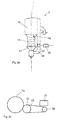
- FIG. 2a shows a yarn feeding device of the monitoring device.
- the yarn feeding device is a storage yarn feeding device 2 with a winding body designed as a storage drum 14.
- the stationary storage drum 14 is arranged in front of a housing 15. At the inlet end of the storage drum 14, a take-up element 16 for winding yarn turns on the storage drum 14 is arranged. At the other end, i.e. at the outlet end, the storage drum 14, is e.g. a cone brake 17 is provided. The cone brake 17 is supported by a boom 18 of the housing 15.
- the memory yarn feeding device 2 is associated with a sensor device 19 and a control unit 20.
- the sensor device 19 is designed to generate a sensor signal with one measurement pulse I per unit length of a yarn delivery path .DELTA.XF.
- the unit length of the yarn delivery path ⁇ XF corresponds to a yarn turn taken from the storage drum 14.
- the sensor device 19 is designed, for example, as an optical sensor which generates a measuring pulse I for each unwound yarn winding.
- the circumference of the storage drum 14, and thus the length of a yarn turn is 20 cm, i. the unit length of the thread delivery path ⁇ XF is 20 cm.
- the control unit has, for example, a microprocessor. It is designed to evaluate the sensor signal of the sensor device 19 and possibly to generate a stop signal ST for the knitting machine.
- the control unit 20 is integrated in the housing 15, but in FIG. 2a shown separately for clarity.
- the clock unit integrated in the control unit 13 is designed to provide the respective control unit 20 with a clock signal S2.
- the clock unit is designed to generate the clock signal S2 from a clock signal S1 of a clock unit.
- FIG. 2b shows a schematic representation of an arrangement of the clock unit, which has a measuring unit, namely a rotary encoder 21.
- the rotary encoder 21 is arranged on a drive 22 which is connected via a drive belt 23 to a drive wheel 24 for the knitting cylinder 7.
- the clock unit with the rotary encoder 21 generates the clock signal S1, which in this example has a number m of approximately 1000 pulses P per revolution of the knitting cylinder 7.
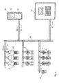
- FIG. 3 shows on the basis of a block diagram that devices of the circular knitting machine 1 are interconnected by communication links 30.
- the communication links 30 are formed as lines and guided on the support rings 5 and parts of the frame 11.
- the communication links 30 are in FIG. 1 not shown. Data is exchanged between the connected devices via the communication links 30.
- the communication links 30 are designed, for example, as two lines of CAN-BUS connections via which a serial data transmission takes place.
- the monitoring device the at least one yarn feeding device, namely at least the in FIG. 2a illustrated storage yarn feeding device 2, the clock unit with the in FIG. 2b shown encoder 21 and the control unit 13 is connected via the communication links 30 to the machine control 12.
- the control unit 13 is in the in FIG. 3 embodiment shown as an electronic device and provided with an input unit 31 and a display unit 32.
- the control unit 13 is possibly designed CAN-bus capable and provided, for example, with a microprocessor.
- the clock unit in the control unit 13 is designed to generate from the clock signal S1 from the clock unit with the rotary encoder 21 the clock signal S2 and to provide the control unit or units 20. That the control unit 13 receives the clock signal S1 from the clock unit and sends the generated clock signal S2 to the control units of the yarn feeding devices, in particular to the control units 20 of the storage yarn feeding devices 2.
- the clock unit in the control unit 13 is configured to use every Nth pulse P of the clock signal S1 as clock pulse T of the clock signal S2, where N is an integer number.
- the clock unit Upon initialization of the monitoring device, the clock unit once determines the number m of pulses P per revolution of the knitting cylinder 7. For this purpose, the clock unit receives a machine cycle signal from the machine control 12, for example.
- the integer number N is determined on the basis of these data by the clock unit possibly once and automatically.
- the number m of about 1000 and a circumference of the knitting cylinder 7 of 250 cm results in an integer of 20. That is, the clock unit is adapted to every 20th pulse P of the clock signal S1 as Clock pulse T of the clock signal S2 to use.
- the clock signal S2 has a clock pulse T per unit length of the knitting path .DELTA.XS. That the clock pulses T of the clock signal S2 provided by the control unit 13 of the control unit 20 correspond to a unit length of the knitting path ⁇ XS, respectively.
- the length unit of the knitting path ⁇ XS is smaller than the length unit of the yarn delivery path ⁇ XF by a factor Z of at least 2, preferably from 3 to 10.
- the factor Z has the value 4.
- Each control unit 20 is designed to evaluate the sensor signal S as a function of the clock signal S2 by counting, starting with a pulse I of the sensor signal S, a number A of clocks T2, comparing it with a predetermined number Ac and, if exceeded, a stop signal ST for the Knitting machine generated.
- the yarn delivery of at least one yarn feeding device is monitored by corresponding sensor devices 19 and control units 20.
- the respective sensor device 19 is a sensor signal S with a measuring pulse I per unit length of the yarn delivery path .DELTA.XF, i. per deducted from the storage drum 14 of the storage yarn feeding device 2 yarn winding generated.
- the respective control unit 20 evaluates the sensor signal S as a function of the clock signal S2 provided by the central control unit 13 with a clock pulse T per unit length of the knitting path ⁇ XS.
- the clock signal S2 is generated by the control unit 13 from the clock signal S1, in this example using every 20th pulse P of the clock signal S1 as the clock pulse T of the clock signal S2.
- the clock signal S1 is, as described, provided by the clock unit with the rotary encoder 21, which determines it as a function of the rotation of the knitting cylinder 7 of the circular knitting machine 1.
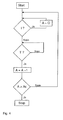
- FIG. 4 shows by means of a flow chart, the evaluation of the sensor signal S by a control unit 20.
- the control unit 20 counts starting with a measuring pulse I a number A of clock pulses T. At each clock pulse T, the control unit 20 compares the number A with a predetermined number Ac.
- the number Ac is a constant that is given depending on the knitted product. The number Ac is entered by an operator over the
- Input unit 31 of the control unit 13 is inputted and provided by the clock unit to the control units 20.
- the number Ac is determined in this example from the factor Z.
- a value Ac is determined which is greater than the factor Z by a safety value z, for example of 2.
- Ac x Z
- a value Ac is determined which is greater by a safety factor x of 1.5 or 3 than the factor Z.
- the predetermined number Ac is chosen depending on the pattern of the product, depending on the bond.
- the predetermined number Ac is determined, for example, in a binding float from the factor Z of 4 multiplied by a safety factor x of 2 to the value 8. In a binding stitch, about one-third of this, for example a value of 3, is determined for the given number Ac. That For example, in a product using bonds with higher thread consumption, a predetermined number Ac may be less than the Z factor. For example, for a product using both mesh and float bindings, a predetermined number Ac of 6 is determined.
- a stop signal ST for the circular knitting machine 1 is generated by the control unit 20 and supplied to the machine controller 12 via the communication link 30 of the knitting machine.
- FIG. 2b shows an alternative timing unit, namely designed as a timing unit sensor device for the positive yarn feeding devices 4, for measuring the knitting path of the circular knitting machine first
- the timing unit comprises a measuring unit 41 and a processing unit 42. It is arranged on a drive belt 43 for the positive yarn feeding devices 4.
- the drive belt or belts 23 are in FIG. 1 only partially shown.
- the measuring unit 41 has at least one measuring wheel 44 driven by the drive belt 43 and at least one sensor 45 and a housing 46.
- the processing unit 42 is arranged in the housing 46.
- the measuring wheel 44 is provided with a plurality of measuring points 47 distributed on an outer circumference of the measuring wheel 41.
- a measuring point 47 is formed, for example, as a bore in which a magnet is arranged.
- the sensor 45 is arranged on or partially in the housing 46 and aligned with the measuring points 47 of the measuring wheel 44.
- the sensor 45 is designed as a Hall sensor.
- an optical sensor for example with a light-emitting diode and a photocell, which are aligned, for example, on light-reflecting measuring points.
- the sensor 45 of the measuring unit 41 When the measuring wheel 44 rotates, the sensor 45 of the measuring unit 41 generates the clock signal S1, each with a pulse P, when one of the measuring points 47 passes the sensor 45.
- the number of measuring wheels 44 and the sensors 45 corresponds to the number of drive wheels of the positive yarn feeding devices 4. In this example, two measuring wheels 44 and two sensors 45 are provided in each case.
- a third example corresponds to the first example except for the features described below.
- a monitoring device is provided on a circular knitting machine on which at least storage yarn feeding devices 2 are arranged.
- the monitoring device comprises a plurality of storage yarn feeding devices 2, which are arranged on a machine ring 5 and have sensor devices and control units, and a clock unit, which is integrated into the control unit 13.
- the storage yarn feeding devices 2 and the control unit 13 are connected to each other via communication lines 30. That is, the clock unit is connected via the communication lines 30 with the control units 20 of the yarn feeding devices 2.
- the clock unit of the control unit 13 is designed as a clock unit, specifically to generate a clock signal S1 from sensor signals S with measuring pulses I of the sensor devices 19 of a plurality of storage yarn feeding devices 2.
- measuring pulses I of the sensor signals S are made available in the control unit 13 via the communication lines 30 of the clock unit.
- the measuring pulses I of Sensor signals S are interpreted by the clock unit as pulses P of the clock signal S1.
- each Nth pulse P is used by the clock unit as the clock pulse T of the clock signal S2.
- the calculation of the integer N is carried out as in the first example, wherein in a starting phase the number m of the pulses P, i. the measuring pulses I of the sensor signals, per revolution of the knitting cylinder 7 is determined. With 8 storage yarn feeding devices and a determination of the number m predominantly at the binding float, with a circumference of the storage drums of 20 cm and a circumference of the knitting cylinder of 250 cm, a number of m of the order of 100 is determined.
- the integer number N has a value of 2 cm for a length unit of the knitting path of 5 cm. through the clock unit every 2nd pulse P is used as clock pulse T.
- the binding is not known exactly, the predetermined number Ac, which is determined from the factor Z with the value 4, with a greater safety value z or safety factor x determined.
Applications Claiming Priority (1)
| Application Number | Priority Date | Filing Date | Title |
|---|---|---|---|
| DE102013110988.8A DE102013110988B4 (de) | 2013-10-02 | 2013-10-02 | Verfahren und Vorrichtung zur Überwachung der Produktion einer Strickmaschine sowie Strickmaschine |
Publications (2)
| Publication Number | Publication Date |
|---|---|
| EP2857567A1 true EP2857567A1 (fr) | 2015-04-08 |
| EP2857567B1 EP2857567B1 (fr) | 2017-03-08 |
Family
ID=51584928
Family Applications (1)
| Application Number | Title | Priority Date | Filing Date |
|---|---|---|---|
| EP14183885.4A Active EP2857567B1 (fr) | 2013-10-02 | 2014-09-08 | Procédé et dispositif de surveillance de la production d'une machine à tricoter |
Country Status (5)
| Country | Link |
|---|---|
| EP (1) | EP2857567B1 (fr) |
| CN (1) | CN104514078B (fr) |
| DE (1) | DE102013110988B4 (fr) |
| TR (1) | TR201707952T4 (fr) |
| TW (1) | TWI564447B (fr) |
Cited By (2)
| Publication number | Priority date | Publication date | Assignee | Title |
|---|---|---|---|---|
| EP3269857A1 (fr) | 2016-07-15 | 2018-01-17 | L.G.L. Electronics S.p.A. | Procédé de commande du déroulement de fil à partir d'une alimentation en trame |
| EP3699343A1 (fr) * | 2019-02-25 | 2020-08-26 | Memminger-IRO GmbH | Procédé et système de surveillance de la production d'une machine à tricoter pourvue d'une pluralité de dispositifs d'alimentation en fil |
Families Citing this family (5)
| Publication number | Priority date | Publication date | Assignee | Title |
|---|---|---|---|---|
| DE102015104903B3 (de) * | 2015-03-30 | 2016-06-16 | Memminger-Iro Gmbh | Verfahren und Vorrichtung zur Überwachung der Produktion einer Strickmaschine sowie Strickmaschine |
| ITUB20155502A1 (it) * | 2015-11-12 | 2017-05-12 | Camozzi Digital S R L | Sistema di monitoraggio di parametri di funzionamento di componenti di un telaio per tessitura |
| CN106987998B (zh) * | 2017-05-24 | 2020-03-17 | 泉州威廉针织科技研究院股份有限公司 | 一种针织圆纬机送纱控制方法 |
| KR102223031B1 (ko) * | 2019-03-20 | 2021-03-04 | 삼성전자주식회사 | 향상된 브레이드 클락 시그널링을 이용한 차동 신호 처리장치 |
| CN114481436B (zh) * | 2022-02-08 | 2023-10-20 | 庸博(厦门)电气技术有限公司 | 一种输纱器的断线检测方法、装置、设备及可读存储介质 |
Citations (8)
| Publication number | Priority date | Publication date | Assignee | Title |
|---|---|---|---|---|
| EP0122582A1 (fr) * | 1983-04-07 | 1984-10-24 | Aktiebolaget Iro | Dispositif fournisseur de fil et procédé pour sa commande |
| US6112557A (en) * | 1998-11-27 | 2000-09-05 | Carla A. Taylor | Flat bed yarn measuring device and method |
| EP0752631B1 (fr) | 1995-07-03 | 2002-04-17 | B.T.S.R. International S.p.A. | Dispositif de surveillance du chargement d'une pluralité de fils pour une machine textile ayant des capteurs encodés et méthode de commande du dispositif |
| EP1335054A2 (fr) * | 2002-01-28 | 2003-08-13 | L.G.L. Electronics S.p.A. | Procédé et dispositif pour mesurer le fil de trame, en particulier dans les métiers à tricoter circulaires électroniques |
| EP1370720A1 (fr) | 2001-03-16 | 2003-12-17 | Memminger-IRO GmbH | Procede de reglage/surveillance de production d'un metier a tricoter circulaire et dispositif de reglage/surveillance de production |
| WO2007062740A1 (fr) * | 2005-12-01 | 2007-06-07 | Memminger-Iro Gmbh | Procede et dispositif de determination de la quantite de fil sur une machine a tricoter |
| WO2008083691A1 (fr) | 2006-12-22 | 2008-07-17 | Memminger-Iro Gmbh | Dévidoir de fil doté d'un débrayage amélioré |
| EP2270269B1 (fr) | 2009-07-03 | 2011-10-26 | L.G.L. Electronics S.p.A. | Procédé de détection de l'arrêt du déroulement du fil dans un dispositif d'alimentation de fil doté d'un tambour stationnaire |
Family Cites Families (5)
| Publication number | Priority date | Publication date | Assignee | Title |
|---|---|---|---|---|
| GB1218181A (en) * | 1967-02-28 | 1971-01-06 | Nat Res Dev | Improved apparatus for use in knitting machines |
| JPS59106548A (ja) * | 1982-12-11 | 1984-06-20 | 株式会社島精機製作所 | 度目調整方法 |
| DE3729297C1 (de) * | 1987-09-02 | 1989-03-02 | Gustav Memminger | Vorrichtung zur UEberwachung der Fadenlieferung bei einer Fadenliefervorrichtung fuer Textilmaschinen |
| GB0318271D0 (en) * | 2003-08-05 | 2003-09-10 | Univ Manchester | Improved knitting machines and methods of knitting |
| EP2415916B1 (fr) * | 2010-08-04 | 2015-03-04 | L.G.L. Electronics S.p.A. | Procédé et appareil pour détecter des arrêts accidentels de fil dans une chaîne de fabrication tricotage |
-
2013
- 2013-10-02 DE DE102013110988.8A patent/DE102013110988B4/de not_active Expired - Fee Related
-
2014
- 2014-09-08 EP EP14183885.4A patent/EP2857567B1/fr active Active
- 2014-09-08 TR TR2017/07952T patent/TR201707952T4/tr unknown
- 2014-09-30 TW TW103133845A patent/TWI564447B/zh active
- 2014-10-08 CN CN201410523724.4A patent/CN104514078B/zh active Active
Patent Citations (9)
| Publication number | Priority date | Publication date | Assignee | Title |
|---|---|---|---|---|
| EP0122582A1 (fr) * | 1983-04-07 | 1984-10-24 | Aktiebolaget Iro | Dispositif fournisseur de fil et procédé pour sa commande |
| EP0752631B1 (fr) | 1995-07-03 | 2002-04-17 | B.T.S.R. International S.p.A. | Dispositif de surveillance du chargement d'une pluralité de fils pour une machine textile ayant des capteurs encodés et méthode de commande du dispositif |
| US6112557A (en) * | 1998-11-27 | 2000-09-05 | Carla A. Taylor | Flat bed yarn measuring device and method |
| EP1370720A1 (fr) | 2001-03-16 | 2003-12-17 | Memminger-IRO GmbH | Procede de reglage/surveillance de production d'un metier a tricoter circulaire et dispositif de reglage/surveillance de production |
| EP1370720B1 (fr) | 2001-03-16 | 2006-11-02 | Memminger-IRO GmbH | Procede de reglage/surveillance de production d'un metier a tricoter circulaire et dispositif de reglage/surveillance de production |
| EP1335054A2 (fr) * | 2002-01-28 | 2003-08-13 | L.G.L. Electronics S.p.A. | Procédé et dispositif pour mesurer le fil de trame, en particulier dans les métiers à tricoter circulaires électroniques |
| WO2007062740A1 (fr) * | 2005-12-01 | 2007-06-07 | Memminger-Iro Gmbh | Procede et dispositif de determination de la quantite de fil sur une machine a tricoter |
| WO2008083691A1 (fr) | 2006-12-22 | 2008-07-17 | Memminger-Iro Gmbh | Dévidoir de fil doté d'un débrayage amélioré |
| EP2270269B1 (fr) | 2009-07-03 | 2011-10-26 | L.G.L. Electronics S.p.A. | Procédé de détection de l'arrêt du déroulement du fil dans un dispositif d'alimentation de fil doté d'un tambour stationnaire |
Cited By (2)
| Publication number | Priority date | Publication date | Assignee | Title |
|---|---|---|---|---|
| EP3269857A1 (fr) | 2016-07-15 | 2018-01-17 | L.G.L. Electronics S.p.A. | Procédé de commande du déroulement de fil à partir d'une alimentation en trame |
| EP3699343A1 (fr) * | 2019-02-25 | 2020-08-26 | Memminger-IRO GmbH | Procédé et système de surveillance de la production d'une machine à tricoter pourvue d'une pluralité de dispositifs d'alimentation en fil |
Also Published As
| Publication number | Publication date |
|---|---|
| TWI564447B (zh) | 2017-01-01 |
| EP2857567B1 (fr) | 2017-03-08 |
| DE102013110988B4 (de) | 2019-08-29 |
| DE102013110988A1 (de) | 2015-04-02 |
| CN104514078B (zh) | 2017-04-12 |
| TW201527615A (zh) | 2015-07-16 |
| TR201707952T4 (tr) | 2018-03-21 |
| CN104514078A (zh) | 2015-04-15 |
Similar Documents
| Publication | Publication Date | Title |
|---|---|---|
| EP2857567B1 (fr) | Procédé et dispositif de surveillance de la production d'une machine à tricoter | |
| DE69916693T3 (de) | Vorrichtung zum Steuern der Fadenlieferung zu einer Textilmaschine und Verfahren zum Steuern des Betriebs der Maschine und der Produktion | |
| EP0530492B1 (fr) | Procédé pour la détection de défauts d'un produit textile en bande | |
| DE2736416C3 (de) | Vorrichtung zum Zuführen von Garn zu einer Strickmaschine | |
| DE10234545B4 (de) | Verfahren und Vorrichtung zum Liefern von Fäden | |
| DE3429207C2 (de) | Fadenliefervorrichtung für fadenverbrauchende Textilmaschinen | |
| EP1370720B1 (fr) | Procede de reglage/surveillance de production d'un metier a tricoter circulaire et dispositif de reglage/surveillance de production | |
| DE3732102C1 (de) | Fadenliefervorrichtung fuer Textilmaschinen mit zeitlich unterschiedlichem Fadenverbrauch,insbesondere Strick- und Wirkmaschinen | |
| DE60218130T2 (de) | Verfahren und Vorrichtung zur Messung des Schussfadens, insbesondere in elektronischen Rundstrickmaschinen | |
| DD282252A5 (de) | Vorrichtung zur ueberwachung der fadenlieferung bei einer fadenliefervorrichtung fuer textilmaschinen | |
| EP0658507A1 (fr) | Procédé pour détecter une réserve de fil dans un dispositif pour emmagasiner et délivrer le fil, et dispositif pour emmagasiner et délivrer le fil | |
| DE102015104903B3 (de) | Verfahren und Vorrichtung zur Überwachung der Produktion einer Strickmaschine sowie Strickmaschine | |
| DE4213842C2 (de) | Verfahren und Einrichtung zur Überwachung der Funktion der Nadeln einer Textilmaschine | |
| EP0307769B1 (fr) | Métier à tricoter avec dispositif de changement de fils | |
| DE3629699A1 (de) | Verfahren zur digitalen fadenlaengen-kontrolle an textilmaschinen | |
| DE102012103535B3 (de) | Vorrichtung und Verfahren zur Überwachung der Produktion einer Strickmaschine | |
| EP1954861B1 (fr) | Procede et dispositif de determination de la quantite de fil sur une machine a tricoter | |
| DE3813216C2 (fr) | ||
| EP0728857B1 (fr) | Procédé et dispositif pour enrouler des faisceaux de fils | |
| DE102004017045B3 (de) | Vorrichtung und Verfahren zur Fadenpositivlieferung | |
| DE102012025607A1 (de) | Vorrichtung und Verfahren zur Überwachung der Produktion einer Strickmaschine | |
| DE1804038A1 (de) | Vorrichtung zur Steuerung von Kett-Wirkmaschinen | |
| CH711314A2 (de) | Schiffchenstickmaschine mit Messvorrichtung zur Überwachung der Fadenspannung des Nadelfadens und Verfahren hierzu. | |
| AT504844A1 (de) | Verfahren zum wickeln einer spule, spule und vorrichtung zum erkennen von eigenschaften des spulgutes |
Legal Events
| Date | Code | Title | Description |
|---|---|---|---|
| PUAI | Public reference made under article 153(3) epc to a published international application that has entered the european phase |
Free format text: ORIGINAL CODE: 0009012 |
|
| 17P | Request for examination filed |
Effective date: 20140908 |
|
| AK | Designated contracting states |
Kind code of ref document: A1 Designated state(s): AL AT BE BG CH CY CZ DE DK EE ES FI FR GB GR HR HU IE IS IT LI LT LU LV MC MK MT NL NO PL PT RO RS SE SI SK SM TR |
|
| AX | Request for extension of the european patent |
Extension state: BA ME |
|
| R17P | Request for examination filed (corrected) |
Effective date: 20150922 |
|
| RBV | Designated contracting states (corrected) |
Designated state(s): AL AT BE BG CH CY CZ DE DK EE ES FI FR GB GR HR HU IE IS IT LI LT LU LV MC MK MT NL NO PL PT RO RS SE SI SK SM TR |
|
| GRAP | Despatch of communication of intention to grant a patent |
Free format text: ORIGINAL CODE: EPIDOSNIGR1 |
|
| INTG | Intention to grant announced |
Effective date: 20160413 |
|
| GRAJ | Information related to disapproval of communication of intention to grant by the applicant or resumption of examination proceedings by the epo deleted |
Free format text: ORIGINAL CODE: EPIDOSDIGR1 |
|
| INTC | Intention to grant announced (deleted) | ||
| GRAS | Grant fee paid |
Free format text: ORIGINAL CODE: EPIDOSNIGR3 |
|
| GRAP | Despatch of communication of intention to grant a patent |
Free format text: ORIGINAL CODE: EPIDOSNIGR1 |
|
| INTG | Intention to grant announced |
Effective date: 20160819 |
|
| GRAA | (expected) grant |
Free format text: ORIGINAL CODE: 0009210 |
|
| AK | Designated contracting states |
Kind code of ref document: B1 Designated state(s): AL AT BE BG CH CY CZ DE DK EE ES FI FR GB GR HR HU IE IS IT LI LT LU LV MC MK MT NL NO PL PT RO RS SE SI SK SM TR |
|
| REG | Reference to a national code |
Ref country code: GB Ref legal event code: FG4D Free format text: NOT ENGLISH |
|
| REG | Reference to a national code |
Ref country code: CH Ref legal event code: EP Ref country code: AT Ref legal event code: REF Ref document number: 873622 Country of ref document: AT Kind code of ref document: T Effective date: 20170315 |
|
| REG | Reference to a national code |
Ref country code: IE Ref legal event code: FG4D Free format text: LANGUAGE OF EP DOCUMENT: GERMAN |
|
| REG | Reference to a national code |
Ref country code: DE Ref legal event code: R096 Ref document number: 502014002899 Country of ref document: DE |
|
| REG | Reference to a national code |
Ref country code: LT Ref legal event code: MG4D |
|
| REG | Reference to a national code |
Ref country code: NL Ref legal event code: MP Effective date: 20170308 |
|
| PG25 | Lapsed in a contracting state [announced via postgrant information from national office to epo] |
Ref country code: LT Free format text: LAPSE BECAUSE OF FAILURE TO SUBMIT A TRANSLATION OF THE DESCRIPTION OR TO PAY THE FEE WITHIN THE PRESCRIBED TIME-LIMIT Effective date: 20170308 Ref country code: FI Free format text: LAPSE BECAUSE OF FAILURE TO SUBMIT A TRANSLATION OF THE DESCRIPTION OR TO PAY THE FEE WITHIN THE PRESCRIBED TIME-LIMIT Effective date: 20170308 Ref country code: HR Free format text: LAPSE BECAUSE OF FAILURE TO SUBMIT A TRANSLATION OF THE DESCRIPTION OR TO PAY THE FEE WITHIN THE PRESCRIBED TIME-LIMIT Effective date: 20170308 Ref country code: NO Free format text: LAPSE BECAUSE OF FAILURE TO SUBMIT A TRANSLATION OF THE DESCRIPTION OR TO PAY THE FEE WITHIN THE PRESCRIBED TIME-LIMIT Effective date: 20170608 Ref country code: GR Free format text: LAPSE BECAUSE OF FAILURE TO SUBMIT A TRANSLATION OF THE DESCRIPTION OR TO PAY THE FEE WITHIN THE PRESCRIBED TIME-LIMIT Effective date: 20170609 |
|
| PG25 | Lapsed in a contracting state [announced via postgrant information from national office to epo] |
Ref country code: ES Free format text: LAPSE BECAUSE OF FAILURE TO SUBMIT A TRANSLATION OF THE DESCRIPTION OR TO PAY THE FEE WITHIN THE PRESCRIBED TIME-LIMIT Effective date: 20170308 Ref country code: LV Free format text: LAPSE BECAUSE OF FAILURE TO SUBMIT A TRANSLATION OF THE DESCRIPTION OR TO PAY THE FEE WITHIN THE PRESCRIBED TIME-LIMIT Effective date: 20170308 Ref country code: RS Free format text: LAPSE BECAUSE OF FAILURE TO SUBMIT A TRANSLATION OF THE DESCRIPTION OR TO PAY THE FEE WITHIN THE PRESCRIBED TIME-LIMIT Effective date: 20170308 Ref country code: BG Free format text: LAPSE BECAUSE OF FAILURE TO SUBMIT A TRANSLATION OF THE DESCRIPTION OR TO PAY THE FEE WITHIN THE PRESCRIBED TIME-LIMIT Effective date: 20170608 Ref country code: SE Free format text: LAPSE BECAUSE OF FAILURE TO SUBMIT A TRANSLATION OF THE DESCRIPTION OR TO PAY THE FEE WITHIN THE PRESCRIBED TIME-LIMIT Effective date: 20170308 |
|
| PG25 | Lapsed in a contracting state [announced via postgrant information from national office to epo] |
Ref country code: NL Free format text: LAPSE BECAUSE OF FAILURE TO SUBMIT A TRANSLATION OF THE DESCRIPTION OR TO PAY THE FEE WITHIN THE PRESCRIBED TIME-LIMIT Effective date: 20170308 |
|
| PG25 | Lapsed in a contracting state [announced via postgrant information from national office to epo] |
Ref country code: RO Free format text: LAPSE BECAUSE OF FAILURE TO SUBMIT A TRANSLATION OF THE DESCRIPTION OR TO PAY THE FEE WITHIN THE PRESCRIBED TIME-LIMIT Effective date: 20170308 Ref country code: CZ Free format text: LAPSE BECAUSE OF FAILURE TO SUBMIT A TRANSLATION OF THE DESCRIPTION OR TO PAY THE FEE WITHIN THE PRESCRIBED TIME-LIMIT Effective date: 20170308 Ref country code: EE Free format text: LAPSE BECAUSE OF FAILURE TO SUBMIT A TRANSLATION OF THE DESCRIPTION OR TO PAY THE FEE WITHIN THE PRESCRIBED TIME-LIMIT Effective date: 20170308 Ref country code: SK Free format text: LAPSE BECAUSE OF FAILURE TO SUBMIT A TRANSLATION OF THE DESCRIPTION OR TO PAY THE FEE WITHIN THE PRESCRIBED TIME-LIMIT Effective date: 20170308 |
|
| PG25 | Lapsed in a contracting state [announced via postgrant information from national office to epo] |
Ref country code: PT Free format text: LAPSE BECAUSE OF FAILURE TO SUBMIT A TRANSLATION OF THE DESCRIPTION OR TO PAY THE FEE WITHIN THE PRESCRIBED TIME-LIMIT Effective date: 20170710 Ref country code: SM Free format text: LAPSE BECAUSE OF FAILURE TO SUBMIT A TRANSLATION OF THE DESCRIPTION OR TO PAY THE FEE WITHIN THE PRESCRIBED TIME-LIMIT Effective date: 20170308 Ref country code: PL Free format text: LAPSE BECAUSE OF FAILURE TO SUBMIT A TRANSLATION OF THE DESCRIPTION OR TO PAY THE FEE WITHIN THE PRESCRIBED TIME-LIMIT Effective date: 20170308 Ref country code: IS Free format text: LAPSE BECAUSE OF FAILURE TO SUBMIT A TRANSLATION OF THE DESCRIPTION OR TO PAY THE FEE WITHIN THE PRESCRIBED TIME-LIMIT Effective date: 20170708 |
|
| REG | Reference to a national code |
Ref country code: DE Ref legal event code: R097 Ref document number: 502014002899 Country of ref document: DE |
|
| PLBE | No opposition filed within time limit |
Free format text: ORIGINAL CODE: 0009261 |
|
| STAA | Information on the status of an ep patent application or granted ep patent |
Free format text: STATUS: NO OPPOSITION FILED WITHIN TIME LIMIT |
|
| PG25 | Lapsed in a contracting state [announced via postgrant information from national office to epo] |
Ref country code: DK Free format text: LAPSE BECAUSE OF FAILURE TO SUBMIT A TRANSLATION OF THE DESCRIPTION OR TO PAY THE FEE WITHIN THE PRESCRIBED TIME-LIMIT Effective date: 20170308 |
|
| 26N | No opposition filed |
Effective date: 20171211 |
|
| PG25 | Lapsed in a contracting state [announced via postgrant information from national office to epo] |
Ref country code: SI Free format text: LAPSE BECAUSE OF FAILURE TO SUBMIT A TRANSLATION OF THE DESCRIPTION OR TO PAY THE FEE WITHIN THE PRESCRIBED TIME-LIMIT Effective date: 20170308 |
|
| REG | Reference to a national code |
Ref country code: CH Ref legal event code: PL |
|
| PG25 | Lapsed in a contracting state [announced via postgrant information from national office to epo] |
Ref country code: MC Free format text: LAPSE BECAUSE OF FAILURE TO SUBMIT A TRANSLATION OF THE DESCRIPTION OR TO PAY THE FEE WITHIN THE PRESCRIBED TIME-LIMIT Effective date: 20170308 |
|
| REG | Reference to a national code |
Ref country code: IE Ref legal event code: MM4A |
|
| REG | Reference to a national code |
Ref country code: BE Ref legal event code: MM Effective date: 20170930 |
|
| PG25 | Lapsed in a contracting state [announced via postgrant information from national office to epo] |
Ref country code: LU Free format text: LAPSE BECAUSE OF NON-PAYMENT OF DUE FEES Effective date: 20170908 |
|
| REG | Reference to a national code |
Ref country code: FR Ref legal event code: ST Effective date: 20180531 |
|
| PG25 | Lapsed in a contracting state [announced via postgrant information from national office to epo] |
Ref country code: CH Free format text: LAPSE BECAUSE OF NON-PAYMENT OF DUE FEES Effective date: 20170930 Ref country code: LI Free format text: LAPSE BECAUSE OF NON-PAYMENT OF DUE FEES Effective date: 20170930 Ref country code: IE Free format text: LAPSE BECAUSE OF NON-PAYMENT OF DUE FEES Effective date: 20170908 |
|
| PG25 | Lapsed in a contracting state [announced via postgrant information from national office to epo] |
Ref country code: BE Free format text: LAPSE BECAUSE OF NON-PAYMENT OF DUE FEES Effective date: 20170930 Ref country code: FR Free format text: LAPSE BECAUSE OF NON-PAYMENT OF DUE FEES Effective date: 20171002 |
|
| PG25 | Lapsed in a contracting state [announced via postgrant information from national office to epo] |
Ref country code: MT Free format text: LAPSE BECAUSE OF FAILURE TO SUBMIT A TRANSLATION OF THE DESCRIPTION OR TO PAY THE FEE WITHIN THE PRESCRIBED TIME-LIMIT Effective date: 20170308 |
|
| GBPC | Gb: european patent ceased through non-payment of renewal fee |
Effective date: 20180908 |
|
| PG25 | Lapsed in a contracting state [announced via postgrant information from national office to epo] |
Ref country code: HU Free format text: LAPSE BECAUSE OF FAILURE TO SUBMIT A TRANSLATION OF THE DESCRIPTION OR TO PAY THE FEE WITHIN THE PRESCRIBED TIME-LIMIT; INVALID AB INITIO Effective date: 20140908 |
|
| PG25 | Lapsed in a contracting state [announced via postgrant information from national office to epo] |
Ref country code: GB Free format text: LAPSE BECAUSE OF NON-PAYMENT OF DUE FEES Effective date: 20180908 Ref country code: CY Free format text: LAPSE BECAUSE OF FAILURE TO SUBMIT A TRANSLATION OF THE DESCRIPTION OR TO PAY THE FEE WITHIN THE PRESCRIBED TIME-LIMIT Effective date: 20170308 |
|
| PG25 | Lapsed in a contracting state [announced via postgrant information from national office to epo] |
Ref country code: MK Free format text: LAPSE BECAUSE OF FAILURE TO SUBMIT A TRANSLATION OF THE DESCRIPTION OR TO PAY THE FEE WITHIN THE PRESCRIBED TIME-LIMIT Effective date: 20170308 |
|
| PG25 | Lapsed in a contracting state [announced via postgrant information from national office to epo] |
Ref country code: AL Free format text: LAPSE BECAUSE OF FAILURE TO SUBMIT A TRANSLATION OF THE DESCRIPTION OR TO PAY THE FEE WITHIN THE PRESCRIBED TIME-LIMIT Effective date: 20170308 |
|
| REG | Reference to a national code |
Ref country code: AT Ref legal event code: MM01 Ref document number: 873622 Country of ref document: AT Kind code of ref document: T Effective date: 20190908 |
|
| PG25 | Lapsed in a contracting state [announced via postgrant information from national office to epo] |
Ref country code: AT Free format text: LAPSE BECAUSE OF NON-PAYMENT OF DUE FEES Effective date: 20190908 |
|
| PGFP | Annual fee paid to national office [announced via postgrant information from national office to epo] |
Ref country code: TR Payment date: 20230901 Year of fee payment: 10 |
|
| PGFP | Annual fee paid to national office [announced via postgrant information from national office to epo] |
Ref country code: DE Payment date: 20230919 Year of fee payment: 10 |
|
| PGFP | Annual fee paid to national office [announced via postgrant information from national office to epo] |
Ref country code: IT Payment date: 20230929 Year of fee payment: 10 |
|
| REG | Reference to a national code |
Ref country code: DE Ref legal event code: R082 Ref document number: 502014002899 Country of ref document: DE Representative=s name: PAUL & ALBRECHT PATENTANWAELTE PARTG MBB, DE |