EP2857567A1 - Method and device for monitoring the production of a knitting machine - Google Patents
Method and device for monitoring the production of a knitting machine Download PDFInfo
- Publication number
- EP2857567A1 EP2857567A1 EP14183885.4A EP14183885A EP2857567A1 EP 2857567 A1 EP2857567 A1 EP 2857567A1 EP 14183885 A EP14183885 A EP 14183885A EP 2857567 A1 EP2857567 A1 EP 2857567A1
- Authority
- EP
- European Patent Office
- Prior art keywords
- unit
- clock
- clock signal
- knitting
- yarn
- Prior art date
- Legal status (The legal status is an assumption and is not a legal conclusion. Google has not performed a legal analysis and makes no representation as to the accuracy of the status listed.)
- Granted
Links
- 238000009940 knitting Methods 0.000 title claims abstract description 162
- 238000000034 method Methods 0.000 title claims abstract description 22
- 238000004519 manufacturing process Methods 0.000 title claims abstract description 16
- 238000012544 monitoring process Methods 0.000 title claims abstract description 16
- 238000011156 evaluation Methods 0.000 claims abstract description 8
- 238000004804 winding Methods 0.000 claims description 19
- 230000004044 response Effects 0.000 claims description 3
- 238000004891 communication Methods 0.000 description 15
- 238000012806 monitoring device Methods 0.000 description 14
- 230000006870 function Effects 0.000 description 11
- 230000027455 binding Effects 0.000 description 9
- 238000009739 binding Methods 0.000 description 9
- 238000005259 measurement Methods 0.000 description 8
- 238000010586 diagram Methods 0.000 description 4
- 239000004753 textile Substances 0.000 description 4
- 230000001419 dependent effect Effects 0.000 description 3
- 230000003287 optical effect Effects 0.000 description 3
- 238000012545 processing Methods 0.000 description 3
- 230000005540 biological transmission Effects 0.000 description 1
- 239000004020 conductor Substances 0.000 description 1
- 239000004744 fabric Substances 0.000 description 1
- 230000000737 periodic effect Effects 0.000 description 1
- 230000001105 regulatory effect Effects 0.000 description 1
Images


Classifications
-
- D—TEXTILES; PAPER
- D04—BRAIDING; LACE-MAKING; KNITTING; TRIMMINGS; NON-WOVEN FABRICS
- D04B—KNITTING
- D04B15/00—Details of, or auxiliary devices incorporated in, weft knitting machines, restricted to machines of this kind
- D04B15/38—Devices for supplying, feeding, or guiding threads to needles
- D04B15/48—Thread-feeding devices
- D04B15/482—Thread-feeding devices comprising a rotatable or stationary intermediate storage drum from which the thread is axially and intermittently pulled off; Devices which can be switched between positive feed and intermittent feed
- D04B15/484—Yarn braking means acting on the drum
-
- D—TEXTILES; PAPER
- D04—BRAIDING; LACE-MAKING; KNITTING; TRIMMINGS; NON-WOVEN FABRICS
- D04B—KNITTING
- D04B35/00—Details of, or auxiliary devices incorporated in, knitting machines, not otherwise provided for
- D04B35/10—Indicating, warning, or safety devices, e.g. stop motions
- D04B35/12—Indicating, warning, or safety devices, e.g. stop motions responsive to thread consumption
-
- D—TEXTILES; PAPER
- D04—BRAIDING; LACE-MAKING; KNITTING; TRIMMINGS; NON-WOVEN FABRICS
- D04B—KNITTING
- D04B35/00—Details of, or auxiliary devices incorporated in, knitting machines, not otherwise provided for
- D04B35/10—Indicating, warning, or safety devices, e.g. stop motions
- D04B35/14—Indicating, warning, or safety devices, e.g. stop motions responsive to thread breakage
Definitions
- the invention relates to a method and a device for monitoring the production of a knitting machine.
- the control unit polls the sensor devices individually based on a periodic reference signal that is a function of the operating position of the textile machine, according to the data regarding the state of supply of the threads.
- the control unit controls the operation of the textile machine with the data from the sensor devices. It interrupts the operation of the textile machine when a difference occurs between the data obtained from at least one sensor device and the corresponding stored data.
- a production monitoring / adjustment device and a corresponding method for a knitting machine, in particular a circular knitting machine are in the EP 1 370 720 B1 described.
- the apparatus comprises a plurality of knitting systems, a plurality of delivery devices and a computerized unit, the delivery devices being connected to the computerized unit.
- the production monitor / adjuster receives trig signals.
- yarn is delivered to the active knitting systems of a plurality of non-positive delivering delivery devices according to at least two distinct yarn delivery principles.
- the individual yarn quantities are continuously measured by means of sampled actual rotation signals at the delivery devices.
- the individual yarn quantities are compared in the computerized unit with nominal yarn quantities of about a masterpiece and information and / or adjustment measures derived from the comparisons. Tolerances are defined for the comparisons, which are matched in their width to yarn quality and / or yarn path parameters. Exceeding the different tolerance ranges is used to trigger different measures, such as alarm signals, adjustment measures or switching off the knitting machine.
- the individual Yarn quantities are also used to determine a total amount of yarn and / or a yarn weight, being converted or converted into equal units or weight units.
- the knitting machine with its machine control, the production monitoring / adjustment device and the delivery devices are connected via a bus system, e.g. a CAN bus system or a daisy chain linked.
- a bus system e.g. a CAN bus system or a daisy chain linked.
- yarn quantities of a certain size are compared with their target yarn quantities.
- the individual yarn quantities are determined, for example, for knitting paths which correspond to one or more revolutions of the knitting cylinder of the circular knitting machine.
- the EP 2 270 269 B1 describes a method for detecting the stopping of yarn unwinding from a yarn feeder to a downstream machine.
- the yarn feeder has a stationary drum and a sensor, through whose sensor signal one pulse is generated per loop unwound from the drum.
- the machine is stopped when a measured time since the last pulse exceeds a setpoint for the time between two pulses.
- the setpoint is updated in real time depending on the yarn unwinding speed.
- the object of the invention is to improve a method and a device for monitoring the production of a knitting machine.
- it is the task of Invention to allow a quick stop the knitting machine at yarn standstill or yarn breakage with little effort.
- the object is achieved by a method according to claim 1.
- An inventive method relates to the monitoring of the production of a knitting machine and allows in particular with little effort a rapid stopping of the knitting machine in yarn standstill or yarn breakage.
- a knitting machine is designed, for example, as a circular knitting machine or a flat knitting machine.
- a circular knitting machine has several or a plurality of identical or different yarn feeding devices.
- Yarn feeding devices are, for example, positive yarn feeding devices, thread tension controlled yarn feeding devices or storage yarn feeding devices. Thread tension controlled thread feeders and store thread feeders are used when making knitwear with patterns.
- the thread delivery takes place at storage yarn feeding devices in which the thread is withdrawn from, for example, a winding body.
- the yarn delivery takes place, in which the thread tension is regulated and the yarn is delivered accordingly.
- the yarn delivery of the Postiv yarn feeding devices is a feeding of the thread synchronously to the speed of the knitting machine.
- the yarn delivery of at least one yarn feeding device is monitored by a sensor device and a control unit.
- a sensor signal is generated with one measurement pulse per unit length of a yarn delivery path.
- This sensor signal is evaluated by the control unit.
- a stop signal for the knitting machine is generated by the control unit.
- the respective control unit is provided by a clock unit, a clock signal available.
- a clock pulse of the clock signal corresponds to a unit length of a knitting path.
- the length unit of the knitting path is smaller by a factor of at least 2 than the unit length of the yarn feeding path.
- the factor is 3 to 10.
- the sensor signal indicating the yarn delivery path is evaluated by the control unit as a function of the clock signal indicating the knitting path.
- a stop signal for the knitting machine is possibly generated by the control unit.
- the knitting path is defined in the context of the invention in a circular knitting machine as the distance traveled by the outer diameter of the knitting cylinder, on which the knitting needles are. That in one revolution of the knitting cylinder, the knitting path corresponds to the outer circumference of the knitting cylinder.
- the knitting path is defined in a flat knitting machine as the path traveled along the needle bed by the carriage.
- individual measuring pulses are evaluated in response to a specific clock signal, which represents a measure of the knitting path, for monitoring yarn delivery, for example, for yarn breakage.
- the clock signal is selected or generated so that at least 2 clock pulses are available per measuring pulse.
- a certain number of these clock pulses corresponds to a certain length of the knitting path. It is independent of the machine speed of the knitting machine and also of the withdrawal speed of the thread. In operation, a number of clock pulses can be determined simply by counting.
- the length unit of the knitting path is 2 to 8 cm. It is preferably 4 to 6 cm.
- a number of clock pulses of the clock signal are counted by the control unit for evaluating the sensor signal in each case starting with a measurement pulse.
- the number of detected clock pulses is compared with a predetermined number.
- the predetermined number corresponds to the factor given above, which corresponds to the ratio of the unit length of the yarn delivery path to the length unit of the knitting path, or is determined from the factor.
- the predetermined number for a yarn feeding device is selected in one embodiment, depending on the binding, such as mesh, float and handle, the knitted product.
- the predetermined number in the case of binding floats corresponds, for example, to the order of magnitude of the factor Z. For example, in the binding loop, it is reduced to one-third of the factor Z. For example, when changing binding within a product, an average value is chosen.
- a predetermined number plus a safety constant or multiplied by a safety value is selected as a predetermined number as determined.
- a stop signal for the knitting machine is generated by the control unit. Exceeding the given number indicates that the thread is being delivered too slowly or broken.
- the number of clock pulses that trigger a stop signal is constant even if the withdrawal speed of the thread changes by changing the speed of the knitting machine. An additional consideration of the take-off speed is not necessary. This monitoring of the yarn delivery is possible only by using a dependent of the knitting path clock signal.
- the length unit of the yarn delivery path corresponds to a wound from a winding body of the yarn feeding device yarn winding or a part of the unwound Garnwindung.
- the yarn feeding device are designed as a storage yarn feeding device and the winding body as a storage drum.
- the clock unit is provided with a clock signal.
- the clock signal is generated by a clock unit depending on the knitting route of the knitting machine.
- the clock signal is used by the clock unit as the clock signal or the clock signal is generated from the clock signal.
- the clock signal is extracted in one embodiment by the timing unit of the machine controller of the knitting machine or generated from one or more machine signals.
- the clock signal is generated in an alternative embodiment by the clock unit by means of a measurement of the traveled knit path.
- the clock signal is provided by a clock unit designed as a clock unit.
- every N th pulse of the clock signal is used as the clock pulse, where N is an integer number.
- the clock signal of a knitting machine designed as a circular knitting machine is determined by the clock unit as a function of the rotation of a knitting cylinder of the circular knitting machine.
- the clock unit has, for example, a mechanical or electronic measuring unit.
- ⁇ XS is the length unit of the knitting path
- m is the number of pulses m of the clock signal per revolution of the knitting cylinder
- U is the circumference of the knitting cylinder.
- the number m of pulses is determined in one example in an initialization of the monitoring device by the clock unit using the machine control.
- the circumference U and the length unit ⁇ XS of the knitting path are predetermined, for example, by an operator.
- each pulse is used as a clock pulse, i. the clock signal is used as a clock signal.
- the clock signal generator signal is generated from sensor signals by the clock unit designed as a clock unit, wherein the sensor signals are provided by sensor devices of one or more yarn feeding devices.
- measurement pulses of the sensor signals from, for example, 6 to 10 storage yarn feeding devices are interpreted by the clock unit designed as a clock unit as pulses of the clock signal.
- the clock unit designed as a clock unit as pulses of the clock signal.
- Nth for example second, pulse as a clock pulse of the clock signal.
- monitoring device for monitoring the production of a knitting machine, referred to below as monitoring device, according to claim 11 and knitting machine according to claim 20.
- monitoring device for monitoring the production of a knitting machine
- knitting machine according to claim 20.
- a monitoring device comprises at least one yarn feeding device.
- Each yarn feeding device of the monitoring device is associated with a sensor device and a control unit.
- the sensor device is designed to generate a sensor signal as a function of a yarn delivery path, i. from the length of the yarn supplied to the knitting machine.
- the sensor device generates a sensor signal with one measurement pulse per unit length of the yarn delivery path.
- the control unit is designed to evaluate the sensor signal of the sensor device and, if necessary, to generate a stop signal for the knitting machine.
- control unit for evaluating the sensor signal is connected to the sensor device.
- control unit is directly connected to the sensor device or connected to it via a communication line.
- the control unit is integrated in one embodiment in the sensor device. It is integrated into the yarn feeder in an alternative. In an alternative, the control unit is designed as a separate device.
- the monitoring device comprises a clock unit, which is designed to provide the control unit (s) with a clock signal dependent on the knitting path of the knitting machine.
- a clock pulse of the clock signal corresponds to a unit length of a knitting route.
- the length unit of the knitting path is selected so that it is smaller by a factor of at least 2 than the length unit of the yarn delivery path.
- the factor is 3 to 10.
- the control unit evaluates the sensor signal as a function of the clock signal provided.
- the length unit of the knitting path is 2 to 8 cm. It is preferably 4 to 6 cm.
- the clock unit is formed in one embodiment as a control unit for the yarn feeding devices or integrated into a control unit. In an alternative embodiment, the clock unit is formed as a separate unit.
- control unit or units are integrated into the clock unit. That the clock unit comprises the control unit of one, several or all sensor devices.
- control unit is designed in each case to count a number of clock pulses beginning with one measurement pulse and to compare the number of clock pulses with a predetermined number.
- the predetermined number corresponds to the factor mentioned above or is determined from it.
- the control unit is configured to generate a stop signal for the knitting machine when the determined number of clock pulses exceeds the predetermined number.
- the yarn feeding device has a winding body, wherein the length unit corresponds to a wound from the wound body of the yarn feeding device yarn winding or a part of the unwound Garnwindung.
- the yarn feeding device is designed as a storage yarn feeding device and the winding body as a storage drum.
- the sensor device is arranged, for example, at the discharge end of the storage drum. It comprises, for example, an optical sensor which transmits one pulse per passing, i. From the drum withdrawn yarn winding generated.
- the monitoring device comprises a clock unit, which is designed to provide a clock signal which is designed as a signal dependent on the knitting path of the knitting machine.
- the clock unit is configured to use the clock signal as the clock signal or to generate the clock signal from the clock signal.
- the clock unit is designed as a clock generator unit.
- the clock unit is connected to or integrated into the machine control.
- the timing unit is connected, for example, to the drive system of the knitting machine.
- the clock unit is configured to generate the clock signal from the clock signal and to use every Nth pulse of the clock signal as a clock pulse.
- N is an integer.
- the knitting machine is designed as a circular knitting machine.
- the clock unit is adapted to generate the clock signal in response to the rotation of a knitting cylinder of the circular knitting machine.
- the clock unit is configured to generate the clock signal at 200 to 2000 or more pulses per revolution of the knitting cylinder of the circular knitting machine.
- the clock signal is generated at approximately 1000 pulses per revolution of the knitting cylinder.
- the number of pulses of the clock signal per unit length of the knitting path is about 20 in this example.
- the clock unit is configured to use from the clock signal every Nth pulse to generate the clock signal.
- the clock unit comprises a measuring unit for measuring the knitting path of the knitting machine.
- the measuring unit comprises e.g. a gear disposed on a drive shaft of the knitting machine or on a shaft connected to the drive shaft.
- the measuring unit is designed as a rotary encoder, wherein the rotary encoder is arranged on the drive of the knitting machine.
- the clock unit comprises a measuring unit which is connected to the drive of positive yarn feeding devices.
- This measuring unit has, for example, a measuring wheel connected to the drive with a sensor.
- the timing unit is integrated into such a specially designed sensor device for determining the delivered yarn amount of one or more positive yarn feeding devices.
- the clock unit designed as a clock unit is designed to generate the clock signal from sensor signals of a plurality of yarn feeding devices.
- the timing unit is connected to control units of, for example, 6 to 10, storage yarn feeding devices.
- the clock unit is designed to be a Clock signal, as described above, to generate from the sensor signals of the storage yarn feeding devices.
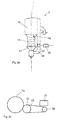
- FIG. 1 shows a schematic view of a circular knitting machine 1 with elements of a device according to the invention for monitoring the production of the knitting machine, hereinafter referred to as monitoring device.
- the circular knitting machine 1 has a plurality of yarn feeding devices, namely as storage yarn feeding devices 2, as voltage-controlled yarn feeding devices 3 and trained as positive yarn feeding devices 4 yarn feeding devices.
- the yarn feeding devices are arranged on a plurality of carrier rings 5 of the circular knitting machines 1. In FIG. 1 only some of the yarn feeding devices are shown, wherein on an upper carrier ring 5 three storage yarn feeding devices 2, on a central carrier ring 5 three Thread tension controlled yarn feeding devices 3 and on a lower carrier ring 5 three positive yarn feeding devices 4 can be seen.
- the circular knitting machine 1 has, for example for the production of a patterned knitted fabric, for example a jacquard knit, several knitting points 6 on its knitting device, wherein each knitting point 6 is associated, for example, with a yarn feeding device.
- the knitting device comprises z. B. a knitting cylinder 7, the in FIG. 1 is covered by knitting locks 8 and is displayed as an arrow.
- FIG. 1 also shows that the knitting point 6, a thread 9 is fed by a storage yarn feeding device 2.
- the knitting device is rotatably arranged in a frame 10, which is surrounded by a housing 11 in the region below the knitting device and to which the carrier rings 5 are fastened in the region above the knitting device.
- a machine control 12 u. a. for a non-visible drive of the knitting device is arranged adjacent to the housing 10.
- the monitoring device comprises at least one yarn feeding device whose yarn delivery is monitored.
- the monitoring device of this example has a clock unit.
- the clock unit is designed as a control unit 13 or integrated into the control unit 13.
- the clock unit is integrated into the control unit 13.
- the control unit 13 is how FIG. 1 shows attached to a central part of the frame 11 of the circular knitting machine 1.
- control unit 13 is detachably held on the frame 11.
- control unit 13 is integrated in the machine control 12.
- FIG. 2a shows a yarn feeding device of the monitoring device.
- the yarn feeding device is a storage yarn feeding device 2 with a winding body designed as a storage drum 14.
- the stationary storage drum 14 is arranged in front of a housing 15. At the inlet end of the storage drum 14, a take-up element 16 for winding yarn turns on the storage drum 14 is arranged. At the other end, i.e. at the outlet end, the storage drum 14, is e.g. a cone brake 17 is provided. The cone brake 17 is supported by a boom 18 of the housing 15.
- the memory yarn feeding device 2 is associated with a sensor device 19 and a control unit 20.
- the sensor device 19 is designed to generate a sensor signal with one measurement pulse I per unit length of a yarn delivery path .DELTA.XF.
- the unit length of the yarn delivery path ⁇ XF corresponds to a yarn turn taken from the storage drum 14.
- the sensor device 19 is designed, for example, as an optical sensor which generates a measuring pulse I for each unwound yarn winding.
- the circumference of the storage drum 14, and thus the length of a yarn turn is 20 cm, i. the unit length of the thread delivery path ⁇ XF is 20 cm.
- the control unit has, for example, a microprocessor. It is designed to evaluate the sensor signal of the sensor device 19 and possibly to generate a stop signal ST for the knitting machine.
- the control unit 20 is integrated in the housing 15, but in FIG. 2a shown separately for clarity.
- the clock unit integrated in the control unit 13 is designed to provide the respective control unit 20 with a clock signal S2.
- the clock unit is designed to generate the clock signal S2 from a clock signal S1 of a clock unit.
- FIG. 2b shows a schematic representation of an arrangement of the clock unit, which has a measuring unit, namely a rotary encoder 21.
- the rotary encoder 21 is arranged on a drive 22 which is connected via a drive belt 23 to a drive wheel 24 for the knitting cylinder 7.
- the clock unit with the rotary encoder 21 generates the clock signal S1, which in this example has a number m of approximately 1000 pulses P per revolution of the knitting cylinder 7.
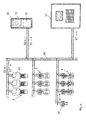
- FIG. 3 shows on the basis of a block diagram that devices of the circular knitting machine 1 are interconnected by communication links 30.
- the communication links 30 are formed as lines and guided on the support rings 5 and parts of the frame 11.
- the communication links 30 are in FIG. 1 not shown. Data is exchanged between the connected devices via the communication links 30.
- the communication links 30 are designed, for example, as two lines of CAN-BUS connections via which a serial data transmission takes place.
- the monitoring device the at least one yarn feeding device, namely at least the in FIG. 2a illustrated storage yarn feeding device 2, the clock unit with the in FIG. 2b shown encoder 21 and the control unit 13 is connected via the communication links 30 to the machine control 12.
- the control unit 13 is in the in FIG. 3 embodiment shown as an electronic device and provided with an input unit 31 and a display unit 32.
- the control unit 13 is possibly designed CAN-bus capable and provided, for example, with a microprocessor.
- the clock unit in the control unit 13 is designed to generate from the clock signal S1 from the clock unit with the rotary encoder 21 the clock signal S2 and to provide the control unit or units 20. That the control unit 13 receives the clock signal S1 from the clock unit and sends the generated clock signal S2 to the control units of the yarn feeding devices, in particular to the control units 20 of the storage yarn feeding devices 2.
- the clock unit in the control unit 13 is configured to use every Nth pulse P of the clock signal S1 as clock pulse T of the clock signal S2, where N is an integer number.
- the clock unit Upon initialization of the monitoring device, the clock unit once determines the number m of pulses P per revolution of the knitting cylinder 7. For this purpose, the clock unit receives a machine cycle signal from the machine control 12, for example.
- the integer number N is determined on the basis of these data by the clock unit possibly once and automatically.
- the number m of about 1000 and a circumference of the knitting cylinder 7 of 250 cm results in an integer of 20. That is, the clock unit is adapted to every 20th pulse P of the clock signal S1 as Clock pulse T of the clock signal S2 to use.
- the clock signal S2 has a clock pulse T per unit length of the knitting path .DELTA.XS. That the clock pulses T of the clock signal S2 provided by the control unit 13 of the control unit 20 correspond to a unit length of the knitting path ⁇ XS, respectively.
- the length unit of the knitting path ⁇ XS is smaller than the length unit of the yarn delivery path ⁇ XF by a factor Z of at least 2, preferably from 3 to 10.
- the factor Z has the value 4.
- Each control unit 20 is designed to evaluate the sensor signal S as a function of the clock signal S2 by counting, starting with a pulse I of the sensor signal S, a number A of clocks T2, comparing it with a predetermined number Ac and, if exceeded, a stop signal ST for the Knitting machine generated.
- the yarn delivery of at least one yarn feeding device is monitored by corresponding sensor devices 19 and control units 20.
- the respective sensor device 19 is a sensor signal S with a measuring pulse I per unit length of the yarn delivery path .DELTA.XF, i. per deducted from the storage drum 14 of the storage yarn feeding device 2 yarn winding generated.
- the respective control unit 20 evaluates the sensor signal S as a function of the clock signal S2 provided by the central control unit 13 with a clock pulse T per unit length of the knitting path ⁇ XS.
- the clock signal S2 is generated by the control unit 13 from the clock signal S1, in this example using every 20th pulse P of the clock signal S1 as the clock pulse T of the clock signal S2.
- the clock signal S1 is, as described, provided by the clock unit with the rotary encoder 21, which determines it as a function of the rotation of the knitting cylinder 7 of the circular knitting machine 1.
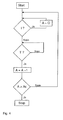
- FIG. 4 shows by means of a flow chart, the evaluation of the sensor signal S by a control unit 20.
- the control unit 20 counts starting with a measuring pulse I a number A of clock pulses T. At each clock pulse T, the control unit 20 compares the number A with a predetermined number Ac.
- the number Ac is a constant that is given depending on the knitted product. The number Ac is entered by an operator over the
- Input unit 31 of the control unit 13 is inputted and provided by the clock unit to the control units 20.
- the number Ac is determined in this example from the factor Z.
- a value Ac is determined which is greater than the factor Z by a safety value z, for example of 2.
- Ac x Z
- a value Ac is determined which is greater by a safety factor x of 1.5 or 3 than the factor Z.
- the predetermined number Ac is chosen depending on the pattern of the product, depending on the bond.
- the predetermined number Ac is determined, for example, in a binding float from the factor Z of 4 multiplied by a safety factor x of 2 to the value 8. In a binding stitch, about one-third of this, for example a value of 3, is determined for the given number Ac. That For example, in a product using bonds with higher thread consumption, a predetermined number Ac may be less than the Z factor. For example, for a product using both mesh and float bindings, a predetermined number Ac of 6 is determined.
- a stop signal ST for the circular knitting machine 1 is generated by the control unit 20 and supplied to the machine controller 12 via the communication link 30 of the knitting machine.
- FIG. 2b shows an alternative timing unit, namely designed as a timing unit sensor device for the positive yarn feeding devices 4, for measuring the knitting path of the circular knitting machine first
- the timing unit comprises a measuring unit 41 and a processing unit 42. It is arranged on a drive belt 43 for the positive yarn feeding devices 4.
- the drive belt or belts 23 are in FIG. 1 only partially shown.
- the measuring unit 41 has at least one measuring wheel 44 driven by the drive belt 43 and at least one sensor 45 and a housing 46.
- the processing unit 42 is arranged in the housing 46.
- the measuring wheel 44 is provided with a plurality of measuring points 47 distributed on an outer circumference of the measuring wheel 41.
- a measuring point 47 is formed, for example, as a bore in which a magnet is arranged.
- the sensor 45 is arranged on or partially in the housing 46 and aligned with the measuring points 47 of the measuring wheel 44.
- the sensor 45 is designed as a Hall sensor.
- an optical sensor for example with a light-emitting diode and a photocell, which are aligned, for example, on light-reflecting measuring points.
- the sensor 45 of the measuring unit 41 When the measuring wheel 44 rotates, the sensor 45 of the measuring unit 41 generates the clock signal S1, each with a pulse P, when one of the measuring points 47 passes the sensor 45.
- the number of measuring wheels 44 and the sensors 45 corresponds to the number of drive wheels of the positive yarn feeding devices 4. In this example, two measuring wheels 44 and two sensors 45 are provided in each case.
- a third example corresponds to the first example except for the features described below.
- a monitoring device is provided on a circular knitting machine on which at least storage yarn feeding devices 2 are arranged.
- the monitoring device comprises a plurality of storage yarn feeding devices 2, which are arranged on a machine ring 5 and have sensor devices and control units, and a clock unit, which is integrated into the control unit 13.
- the storage yarn feeding devices 2 and the control unit 13 are connected to each other via communication lines 30. That is, the clock unit is connected via the communication lines 30 with the control units 20 of the yarn feeding devices 2.
- the clock unit of the control unit 13 is designed as a clock unit, specifically to generate a clock signal S1 from sensor signals S with measuring pulses I of the sensor devices 19 of a plurality of storage yarn feeding devices 2.
- measuring pulses I of the sensor signals S are made available in the control unit 13 via the communication lines 30 of the clock unit.
- the measuring pulses I of Sensor signals S are interpreted by the clock unit as pulses P of the clock signal S1.
- each Nth pulse P is used by the clock unit as the clock pulse T of the clock signal S2.
- the calculation of the integer N is carried out as in the first example, wherein in a starting phase the number m of the pulses P, i. the measuring pulses I of the sensor signals, per revolution of the knitting cylinder 7 is determined. With 8 storage yarn feeding devices and a determination of the number m predominantly at the binding float, with a circumference of the storage drums of 20 cm and a circumference of the knitting cylinder of 250 cm, a number of m of the order of 100 is determined.
- the integer number N has a value of 2 cm for a length unit of the knitting path of 5 cm. through the clock unit every 2nd pulse P is used as clock pulse T.
- the binding is not known exactly, the predetermined number Ac, which is determined from the factor Z with the value 4, with a greater safety value z or safety factor x determined.
Abstract
Ein Verfahren zur Überwachung der Produktion einer Strickmaschine, wobei die Fadenlieferung mindestens eines Fadenliefergerätes durch eine Sensorvorrichtung (19) und eine Kontrolleinheit (20) überwacht wird. Dabei wird ein Sensorsignal (S) mit einem Messimpuls (I) pro Längeneinheit eines Fadenlieferweges (”XF) durch die Sensorvorrichtung (19) erzeugt. Das Sensorsignal (S) wird durch die Kontrolleinheit (20) ausgewertet und ggf. ein Stoppsignal (ST) für die Strickmaschine durch die Kontrolleinheit (20) erzeugt. Durch eine Takteinheit wird der Kontrolleinheit (20) ein Taktsignal (S2) zur Verfügung gestellt wird, wobei ein Taktimpuls (T) des Taktsignals (S2) einer Längeneinheit des Strickweges (”XS) entspricht. Die Längeneinheit des Strickweges (”XS) ist um einen Faktor (Z) von mindestens 2, vorzugsweise von 3 bis 10, kleiner ist als die Längeneinheit des Fadenlieferweges (”XF). Die Auswertung des Sensorsignals (S) durch die Kontrolleinheit (20) erfolgt in Abhängigkeit vom Taktsignal (S2).A method for monitoring the production of a knitting machine, wherein the yarn delivery of at least one yarn feeding device is monitored by a sensor device (19) and a control unit (20). In this case, a sensor signal (S) with a measuring pulse (I) per unit length of a yarn delivery path ("XF) is generated by the sensor device (19). The sensor signal (S) is evaluated by the control unit (20) and, if necessary, a stop signal (ST) for the knitting machine is generated by the control unit (20). A clock unit provides the control unit (20) with a clock signal (S2), wherein a clock pulse (T) of the clock signal (S2) corresponds to a length unit of the knitting path ("XS). The length unit of the knitting path ("XS") is smaller by a factor (Z) of at least 2, preferably from 3 to 10, than the length unit of the yarn feeding path ("XF"). The evaluation of the sensor signal (S) by the control unit (20) takes place as a function of the clock signal (S2).
Description
Die Erfindung betrifft ein Verfahren und eine Vorrichtung zur Überwachung der Produktion einer Strickmaschine.The invention relates to a method and a device for monitoring the production of a knitting machine.
In der Stricktechnik wird vielfach eine Überwachung der laufenden Produktion gewünscht. Dazu ist aus der
Die Steuereinheit fragt die Sensoreinrichtungen individuell aufgrund eines periodischen Referenzsignals, das eine Funktion der Betriebsposition der Textilmaschine ist, nach den Daten bezüglich des Zustandes der Zufuhr der Fäden ab. Die Steuereinheit steuert mit den Daten von den Sensoreinrichtungen den Betrieb der Textilmaschine. Sie unterbricht den Betrieb der Textilmaschine, wenn eine Differenz zwischen den von wenigstens einer Sensoreinrichtung erhaltenen Daten und den entsprechenden gespeicherten Daten auftritt.The control unit polls the sensor devices individually based on a periodic reference signal that is a function of the operating position of the textile machine, according to the data regarding the state of supply of the threads. The control unit controls the operation of the textile machine with the data from the sensor devices. It interrupts the operation of the textile machine when a difference occurs between the data obtained from at least one sensor device and the corresponding stored data.
Eine Produktionsüberwachungs/Einstellvorrichtung und ein entsprechendes Verfahren für eine Strickmaschinen, insbesondere eine Rundstrickmaschine, sind in der
In Betrieb wird Garn zu den aktiven Stricksystemen von mehreren nicht-positiv liefernden Liefergeräten nach zumindest zwei sich unterscheidenden Garn-Förderprinzipien geliefert. Dabei werden die individuellen Garnmengen fortlaufend anhand abgetasteter Ist-Drehsignale an den Liefergeräten gemessen. Die individuellen Garnmengen werden in der computerisierten Einheit mit Soll-Garnmengen etwa eines Masterpieces verglichen und Informationen und/oder Einstellmaßnahmen aus den Vergleichen abgeleitet. Für die Vergleiche sind Toleranzbereiche definiert, die in ihrer Breite auf Garnqualitäts- und/oder Garnwegparameter abgestimmt sind. Das Überschreiten der unterschiedlichen Toleranzbereiche wird zum Auslösen unterschiedlicher Maßnahmen, wie Alarmsignale, Einstellmaßnahmen oder Abschalten der Strickmaschine, genutzt. Die individuellen Garnmengen werden auch zur Feststellung einer Gesamtgarnmenge und/oder eines Garngewichts genutzt, wobei sie in gleiche Mengen- bzw. Gewichtseinheiten umgerechnet oder umgewandelt werden.In operation, yarn is delivered to the active knitting systems of a plurality of non-positive delivering delivery devices according to at least two distinct yarn delivery principles. The individual yarn quantities are continuously measured by means of sampled actual rotation signals at the delivery devices. The individual yarn quantities are compared in the computerized unit with nominal yarn quantities of about a masterpiece and information and / or adjustment measures derived from the comparisons. Tolerances are defined for the comparisons, which are matched in their width to yarn quality and / or yarn path parameters. Exceeding the different tolerance ranges is used to trigger different measures, such as alarm signals, adjustment measures or switching off the knitting machine. The individual Yarn quantities are also used to determine a total amount of yarn and / or a yarn weight, being converted or converted into equal units or weight units.
Die Strickmaschine mit ihrer Maschinensteuerung, die Produktionsüberwachungs-/Einstellvorrichtung und die Liefergeräte sind über ein Bussystem, z.B. ein CAN-Bussystem oder einen Daisy-Chain, verknüpft.The knitting machine with its machine control, the production monitoring / adjustment device and the delivery devices are connected via a bus system, e.g. a CAN bus system or a daisy chain linked.
In oben genannten Schriften werden individuell Daten über Zustände der Fadenzufuhr (
Bei der in der
Es ist außerdem zum Beispiel aus der
Die
Bei dem in der
Die Aufgabe der Erfindung ist es, ein Verfahren und eine Vorrichtung zur Überwachung der Produktion einer Strickmaschine zu verbessern. Insbesondere ist es die Aufgabe der Erfindung, ein schnelles Anhalten der Strickmaschine bei Fadenstillstand oder Fadenbruch mit geringem Aufwand zu ermöglichen.The object of the invention is to improve a method and a device for monitoring the production of a knitting machine. In particular, it is the task of Invention to allow a quick stop the knitting machine at yarn standstill or yarn breakage with little effort.
Die Aufgabe ist durch ein Verfahren gemäß Anspruch 1 gelöst.The object is achieved by a method according to
Ein erfindungsgemäßes Verfahren betrifft die Überwachung der Produktion einer Strickmaschine und ermöglicht insbesondere mit geringem Aufwand ein schnelles Anhalten der Strickmaschine bei Fadenstillstand oder Fadenbruch.An inventive method relates to the monitoring of the production of a knitting machine and allows in particular with little effort a rapid stopping of the knitting machine in yarn standstill or yarn breakage.
Eine Strickmaschine ist zum Beispiel als eine Rundstrickmaschine oder eine Flachstrickmaschine ausgebildet.A knitting machine is designed, for example, as a circular knitting machine or a flat knitting machine.
Eine Rundstrickmaschine weist zum Beispiel mehrere oder eine Vielzahl von gleichen oder unterschiedlichen Fadenliefergeräten auf. Fadenliefergeräte sind zum Beispiel Positiv-Fadenliefergeräte, fadenspannungsgesteuerte Fadenliefergeräte oder Speicher-Fadenliefergeräte. Fadenspannungsgesteuerte Fadenliefergeräte und Speicher-Fadenliefergeräte werden eingesetzt, wenn Strickwaren mit Mustern hergestellt werden.For example, a circular knitting machine has several or a plurality of identical or different yarn feeding devices. Yarn feeding devices are, for example, positive yarn feeding devices, thread tension controlled yarn feeding devices or storage yarn feeding devices. Thread tension controlled thread feeders and store thread feeders are used when making knitwear with patterns.
Die Fadenlieferung erfolgt bei Speicher-Fadenliefergeräten, in dem der Faden von zum Beispiel einem Wickelkörper abgezogen wird. Bei fadenspannungsgesteuerten Fadenliefergeräten erfolgt die Fadenlieferung, in dem die Fadenspannung geregelt und der Faden entsprechend geliefert wird. Bei der Fadenlieferung der Postiv-Fadenliefergeräte handelt es sich um eine Zuführung des Fadens synchron zur Geschwindigkeit der Strickmaschine.The thread delivery takes place at storage yarn feeding devices in which the thread is withdrawn from, for example, a winding body. In the case of yarn tension-controlled yarn feeding devices, the yarn delivery takes place, in which the thread tension is regulated and the yarn is delivered accordingly. The yarn delivery of the Postiv yarn feeding devices is a feeding of the thread synchronously to the speed of the knitting machine.
Bei einem erfindungsgemäßen Verfahren wird die Fadenlieferung mindestens eines Fadenliefergerätes durch eine Sensorvorrichtung und eine Kontrolleinheit überwacht. Durch die Sensorvorrichtung wird ein Sensorsignal mit jeweils einem Messimpuls pro Längeneinheit eines Fadenlieferweges erzeugt. Dieses Sensorsignal wird durch die Kontrolleinheit ausgewertet. Je nach Ergebnis der Auswertung wird durch die Kontrolleinheit ein Stoppsignal für die Strickmaschine erzeugt.In a method according to the invention, the yarn delivery of at least one yarn feeding device is monitored by a sensor device and a control unit. By the sensor device, a sensor signal is generated with one measurement pulse per unit length of a yarn delivery path. This sensor signal is evaluated by the control unit. Depending on the result of the evaluation, a stop signal for the knitting machine is generated by the control unit.
Der jeweiligen Kontrolleinheit wird durch eine Takteinheit ein Taktsignal zur Verfügung gestellt. Ein Taktimpuls des Taktsignals entspricht einer Längeneinheit eines Strickweges. Die Längeneinheit des Strickweges ist um einen Faktor von mindestens 2 kleiner als die Längeneinheit des Fadenlieferweges. Vorzugsweise beträgt der Faktor 3 bis 10.The respective control unit is provided by a clock unit, a clock signal available. A clock pulse of the clock signal corresponds to a unit length of a knitting path. The length unit of the knitting path is smaller by a factor of at least 2 than the unit length of the yarn feeding path. Preferably, the factor is 3 to 10.
Das den Fadenlieferweg anzeigende Sensorsignal wird in Abhängigkeit von dem den Strickweg anzeigenden Taktsignal durch die Kontrolleinheit ausgewertet. Wie erwähnt, wird durch die Kontrolleinheit ggf. ein Stoppsignal für die Strickmaschine erzeugt.The sensor signal indicating the yarn delivery path is evaluated by the control unit as a function of the clock signal indicating the knitting path. As mentioned, a stop signal for the knitting machine is possibly generated by the control unit.
Der Strickweg ist im Rahmen der Erfindung bei einer Rundstrickmaschine definiert als der vom Außendurchmesser des Strickzylinders, an dem sich die Stricknadeln befinden, zurückgelegte Weg. D.h. bei einer Umdrehung des Strickzylinders entspricht der Strickweg dem Außenumfang des Strickzylinders.The knitting path is defined in the context of the invention in a circular knitting machine as the distance traveled by the outer diameter of the knitting cylinder, on which the knitting needles are. That in one revolution of the knitting cylinder, the knitting path corresponds to the outer circumference of the knitting cylinder.
Der Strickweg ist bei einer Flachstrickmaschine definiert als der entlang des Nadelbettes durch den Schlitten zurückgelegte Weg.The knitting path is defined in a flat knitting machine as the path traveled along the needle bed by the carriage.
Bei der vorliegenden Erfindung werden zur Überwachung der Fadenlieferung zum Beispiel auf Fadenbruch einzelne Messimpulse in Abhängigkeit von einem speziellen Taktsignal, das ein Maß für den Strickweg darstellt, ausgewertet. Das Taktsignal ist so ausgewählt oder erzeugt, dass pro Messimpuls mindestens 2 Taktimpulse zur Verfügung stehen.In the present invention, individual measuring pulses are evaluated in response to a specific clock signal, which represents a measure of the knitting path, for monitoring yarn delivery, for example, for yarn breakage. The clock signal is selected or generated so that at least 2 clock pulses are available per measuring pulse.
Die Verwendung eines Taktsignals, das Taktimpulse in Abhängigkeit vom Strickweg zur Verfügung stellt, ermöglicht eine einfache Auswertung eines Sensorsignals, das Messimpulse in Abhängigkeit von einem Fadenlieferweg erzeugt.The use of a clock signal which provides clock pulses as a function of the knitting path makes possible a simple evaluation of a sensor signal which generates measurement pulses as a function of a yarn delivery path.
Eine bestimmte Anzahl dieser Taktimpulse entspricht einer bestimmten Länge des Strickweges. Sie ist unabhängig von der Maschinengeschwindigkeit der Strickmaschine und auch von der Abzugsgeschwindigkeit des Fadens. Im Betrieb ist eine Anzahl von Taktimpulsen einfach durch Zählen zu ermitteln.A certain number of these clock pulses corresponds to a certain length of the knitting path. It is independent of the machine speed of the knitting machine and also of the withdrawal speed of the thread. In operation, a number of clock pulses can be determined simply by counting.
Die Verwendung mehrerer Taktimpulse pro messbare Längeneinheit des Fadenlieferweges, d.h. pro Messimpuls, ermöglicht eine sehr schnelle Auswertung und Reaktion auf Fehler der Fadenlieferung, wie Fadenbruch.The use of multiple clock pulses per measurable length unit of the yarn delivery path, i. per measuring pulse, enables a very fast evaluation and reaction to errors of the thread delivery, such as thread breakage.
Damit ist ein Stoppen der Strickmaschine bei Fadenstillstand oder Fadenbruch durch ein einfaches und zuverlässiges Verfahren ohne Rechenaufwand möglich.This is a stopping of the knitting machine at yarn standstill or yarn breakage by a simple and reliable process without any computational effort.
In einer Ausführungsform beträgt die Längeneinheit des Strickweges 2 bis 8 cm. Bevorzugt beträgt sie 4 bis 6 cm.In one embodiment, the length unit of the knitting path is 2 to 8 cm. It is preferably 4 to 6 cm.
In einer Ausführungsform wird durch die Kontrolleinheit zur Auswertung des Sensorsignals jeweils beginnend mit einem Messimpuls eine Anzahl von Taktimpulsen des Taktsignals gezählt. Die Anzahl der ermittelten Taktimpulse wird mit einer vorgegebenen Anzahl verglichen.In one embodiment, a number of clock pulses of the clock signal are counted by the control unit for evaluating the sensor signal in each case starting with a measurement pulse. The number of detected clock pulses is compared with a predetermined number.
Die vorgegebene Anzahl entspricht dem oben angegebenen Faktor, der dem Verhältnis der Längeneinheit des Fadenlieferweges zur Längeneinheit des Strickweges entspricht, oder wird aus dem Faktor ermittelt.The predetermined number corresponds to the factor given above, which corresponds to the ratio of the unit length of the yarn delivery path to the length unit of the knitting path, or is determined from the factor.
Die vorgegebene Anzahl für ein Fadenliefergerät ist in einem Ausführungsbeispiel in Abhängigkeit von der Bindung, wie Masche, Flottung und Henkel, des gestrickten Produktes gewählt. Dabei entspricht die vorgegebene Anzahl bei der Bindung Flottung zum Beispiel größenordnungsmäßig dem Faktor Z. Sie ist bei der Bindung Masche zum Beispiel auf ein Drittel des Faktors Z erniedrigt. Bei wechselnder Bindung innerhalb eines Produktes wird zum Beispiel ein mittlerer Wert gewählt.The predetermined number for a yarn feeding device is selected in one embodiment, depending on the binding, such as mesh, float and handle, the knitted product. In this case, the predetermined number in the case of binding floats corresponds, for example, to the order of magnitude of the factor Z. For example, in the binding loop, it is reduced to one-third of the factor Z. For example, when changing binding within a product, an average value is chosen.
In einem Ausführungsbeispiel wird als vorgegebene Anzahl eine, wie beschrieben ermittelte, vorgegebene Anzahl zuzüglich einer Sicherheitskonstante oder multipliziert mit einem Sicherheitswert gewählt.In one embodiment, a predetermined number plus a safety constant or multiplied by a safety value is selected as a predetermined number as determined.
Bei Überschreiten der vorgegebenen Anzahl der Taktimpulse wird durch die Kontrolleinheit ein Stoppsignal für die Strickmaschine erzeugt. Das Überschreiten der vorgegebenen Anzahl zeigt an, dass der Faden zu langsam geliefert wird oder gerissen ist.When the predetermined number of clock pulses is exceeded, a stop signal for the knitting machine is generated by the control unit. Exceeding the given number indicates that the thread is being delivered too slowly or broken.
Die Anzahl der Taktimpulse, die ein Stoppsignal auslösen, ist insbesondere auch dann konstant, wenn sich die Abzugsgeschwindigkeit des Fadens durch Änderung der Geschwindigkeit der Strickmaschine ändert. Eine zusätzliche Berücksichtigung der Abzugsgeschwindigkeit ist nicht notwendig. Damit ist eine Überwachung der Fadenlieferung allein durch Verwendung eines vom Strickweg abhängigen Taktsignals möglich.The number of clock pulses that trigger a stop signal is constant even if the withdrawal speed of the thread changes by changing the speed of the knitting machine. An additional consideration of the take-off speed is not necessary. This monitoring of the yarn delivery is possible only by using a dependent of the knitting path clock signal.
In einer Ausführungsform entspricht die Längeneinheit des Fadenlieferweges einer von einem Wickelkörper des Fadenliefergerätes abgewickelten Garnwindung oder einem Teil der abgewickelten Garnwindung.In one embodiment, the length unit of the yarn delivery path corresponds to a wound from a winding body of the yarn feeding device yarn winding or a part of the unwound Garnwindung.
In einer Ausführungsform sind das Fadenliefergerät als ein Speicher-Fadenliefergerät und der Wickelkörper als eine Speichertrommel ausgebildet.In one embodiment, the yarn feeding device are designed as a storage yarn feeding device and the winding body as a storage drum.
In einer Ausführungsform wird der Takteinheit ein Taktgebersignal zur Verfügung gestellt. Das Taktgebersignal wird in Abhängigkeit von dem Strickweg der Strickmaschine durch eine Taktgebereinheit erzeugt. Das Taktgebersignal wird durch die Takteinheit als das Taktsignal verwendet oder das Taktsignal aus dem Taktgebersignal erzeugt.In one embodiment, the clock unit is provided with a clock signal. The clock signal is generated by a clock unit depending on the knitting route of the knitting machine. The clock signal is used by the clock unit as the clock signal or the clock signal is generated from the clock signal.
Das Taktgebersignal wird in einer Ausführungsform durch die Taktgebereinheit der Maschinensteuerung der Strickmaschine entnommen oder aus einem oder mehreren Maschinensignalen erzeugt. Das Taktgebersignal wird in einer alternativen Ausführungsform durch die Taktgebereinheit mit Hilfe einer Messung des zurückgelegten Strickweges erzeugt.The clock signal is extracted in one embodiment by the timing unit of the machine controller of the knitting machine or generated from one or more machine signals. The clock signal is generated in an alternative embodiment by the clock unit by means of a measurement of the traveled knit path.
In einer weiteren Ausführungsform wird das Taktsignal durch eine als Taktgebereinheit ausgebildete Takteinheit zur Verfügung gestellt.In a further embodiment, the clock signal is provided by a clock unit designed as a clock unit.
In einer Ausführungsform, bei der das Taktsignal durch die Takteinheit aus dem Taktgebersignal erzeugt wird, wird jeder N-te Impuls des Taktgebersignals als Taktimpuls verwendet, wobei N eine Integerzahl ist. Mit diesem Verfahren wird ein Taktsignal mit einer verringerten Anzahl von Taktimpulsen pro Strickweg zur Verfügung gestellt. Das erzeugte Taktsignal ist unabhängig von der Maschinengröße und von der Erzeugung des Taktgebersignals. Ein Taktsignal mit einer geringeren Anzahl von Taktimpulsen führt zu einer geringeren Belastung einer Kommunikationsverbindung zwischen der Takteinheit und den Kontrolleinheiten.In an embodiment where the clock signal is generated by the clock unit from the clock signal, every N th pulse of the clock signal is used as the clock pulse, where N is an integer number. With this method, a clock signal with a reduced number of clock pulses per knitting path is provided. The generated clock signal is independent of the machine size and the generation of the clock signal. A clock signal having a smaller number of clock pulses results in less stress on a communication link between the clock unit and the control units.
In einer Ausführungsform wird durch die Taktgebereinheit das Taktgebersignal einer als Rundstrickmaschine ausgebildeten Strickmaschine in Abhängigkeit von der Umdrehung eines Strickzylinders der Rundstrickmaschine ermittelt. Dazu weist die Taktgebereinheit zum Beispiel eine mechanische oder elektronische Messeinheit auf.In one embodiment, the clock signal of a knitting machine designed as a circular knitting machine is determined by the clock unit as a function of the rotation of a knitting cylinder of the circular knitting machine. For this purpose, the clock unit has, for example, a mechanical or electronic measuring unit.
In einer Ausführungsform wird die Integerzahl N folgendermaßen berechnet: ![]()
![]()
Bei einer Integerzahl N gleich 1 wird jeder Impuls als Taktimpuls verwendet, d.h. das Taktgebersignal wird als Taktsignal verwendet.With an integer N equal to 1, each pulse is used as a clock pulse, i. the clock signal is used as a clock signal.
In einer Ausführungsform wird durch die als Taktgebereinheit ausgebildete Takteinheit das Taktsignalgebersignal aus Sensorsignalen erzeugt, wobei die Sensorsignale von Sensorvorrichtungen eines oder mehrerer Fadenliefergeräte zur Verfügung gestellt werden.In one embodiment, the clock signal generator signal is generated from sensor signals by the clock unit designed as a clock unit, wherein the sensor signals are provided by sensor devices of one or more yarn feeding devices.
In einem Beispiel werden Messimpulse der Sensorsignale von, zum Beispiel 6 bis 10, Speicher-Fadenliefergeräten durch die als Taktgebereinheit ausgebildete Takteinheit als Impulse des Taktgebersignals interpretiert. Von diesen Impulsen des Taktgebersignals wird durch die Takteinheit ggf. jeder N-te, zum Beispiel zweite, Impuls als Taktimpuls des Taktsignals verwendet.In one example, measurement pulses of the sensor signals from, for example, 6 to 10, storage yarn feeding devices are interpreted by the clock unit designed as a clock unit as pulses of the clock signal. Of these pulses of the clock signal is used by the clock unit, if necessary, every Nth, for example second, pulse as a clock pulse of the clock signal.
Die Aufgabe ist auch durch eine erfindungsgemäße Vorrichtung zur Überwachung der Produktion einer Strickmaschine, im Folgenden Überwachungsvorrichtung genannt, gemäß Anspruch 11 und Strickmaschine gemäß Anspruch 20 gelöst. Merkmale und Vorteile der Ansprüche 11 bis 19 entsprechen denen der Ansprüche 1 bis 10 und umgekehrt.The object is also achieved by a device according to the invention for monitoring the production of a knitting machine, referred to below as monitoring device, according to claim 11 and knitting machine according to
Eine Überwachungseinrichtung umfasst mindestens ein Fadenliefergerät. Jedem Fadenliefergerät der Überwachungsvorrichtung sind eine Sensorvorrichtung und eine Kontrolleinheit zugeordnet. Die Sensorvorrichtung ist dazu ausgebildet, ein Sensorsignal in Abhängigkeit eines Fadenlieferweges, d.h. von der Länge des zur Strickmaschine gelieferten Fadens, zu erzeugen. Die Sensorvorrichtung erzeugt ein Sensorsignal mit jeweils einem Messimpuls pro Längeneinheit des Fadenlieferweges. Die Kontrolleinheit ist dazu ausgebildet, das Sensorsignal der Sensorvorrichtung auszuwerten und ggf. ein Stopsignal für die Strickmaschine zu erzeugen.A monitoring device comprises at least one yarn feeding device. Each yarn feeding device of the monitoring device is associated with a sensor device and a control unit. The sensor device is designed to generate a sensor signal as a function of a yarn delivery path, i. from the length of the yarn supplied to the knitting machine. The sensor device generates a sensor signal with one measurement pulse per unit length of the yarn delivery path. The control unit is designed to evaluate the sensor signal of the sensor device and, if necessary, to generate a stop signal for the knitting machine.
In einer Ausführungsform ist die Kontrolleinheit zur Auswertung des Sensorsignals mit der Sensorvorrichtung verbunden. Die Kontrolleinheit ist zum Beispiel direkt an die Sensorvorrichtung angeschlossen oder über einer Kommunikationsleitung mit ihr verbunden.In one embodiment, the control unit for evaluating the sensor signal is connected to the sensor device. For example, the control unit is directly connected to the sensor device or connected to it via a communication line.
Die Kontrolleinheit ist in einer Ausführungsform in die Sensorvorrichtung integriert. Sie ist in einer Alternative in das Fadenliefergerät integriert. In eine Alternative ist die Kontrolleinheit als separate Vorrichtung ausgeführt.The control unit is integrated in one embodiment in the sensor device. It is integrated into the yarn feeder in an alternative. In an alternative, the control unit is designed as a separate device.
Die Überwachungseinrichtung umfasst eine Takteinheit, die dazu ausgebildet ist, der oder den Kontrolleinheiten ein vom Strickweg der Strickmaschine abhängiges Taktsignal zur Verfügung zu stellen. Wie beschrieben, entspricht ein Taktimpuls des Taktsignals einer Längeneinheit eines Strickweges. Die Längeneinheit des Strickweges ist so gewählt, dass sie um einen Faktor von mindestens 2 kleiner ist als die Längeneinheit des Fadenlieferweges. Vorzugsweise beträgt der Faktor 3 bis 10. Die Kontrolleinheit wertet das Sensorsignal in Abhängigkeit von dem zur Verfügung gestellten Taktsignal aus.The monitoring device comprises a clock unit, which is designed to provide the control unit (s) with a clock signal dependent on the knitting path of the knitting machine. As described, a clock pulse of the clock signal corresponds to a unit length of a knitting route. The length unit of the knitting path is selected so that it is smaller by a factor of at least 2 than the length unit of the yarn delivery path. Preferably, the factor is 3 to 10. The control unit evaluates the sensor signal as a function of the clock signal provided.
Wie erwähnt, beträgt in einer Ausführungsform die Längeneinheit des Strickweges 2 bis 8 cm. Bevorzugt beträgt sie 4 bis 6 cm.As mentioned, in one embodiment, the length unit of the knitting path is 2 to 8 cm. It is preferably 4 to 6 cm.
Die Takteinheit ist in einer Ausführungsform als eine Steuereinheit für die Fadenliefergeräte ausgebildet oder in eine Steuereinheit integriert. In einer alternativen Ausführungsform ist die Takteinheit als eine separate Einheit ausgebildet.The clock unit is formed in one embodiment as a control unit for the yarn feeding devices or integrated into a control unit. In an alternative embodiment, the clock unit is formed as a separate unit.
In einer Ausführungsform ist die Kontrolleinheit oder sind die Kontrolleinheiten in die Takteinheit integriert. D.h. die Takteinheit umfasst die Kontrolleinheit einer, mehrerer oder aller Sensorvorrichtungen.In one embodiment, the control unit or units are integrated into the clock unit. That the clock unit comprises the control unit of one, several or all sensor devices.
In einer Ausführungsform ist die Kontrolleinheit dazu ausgebildet, jeweils beginnend mit einem Messimpuls eine Anzahl von Taktimpulsen zu zählen und die Anzahl der Taktimpulse mit einer vorgegebenen Anzahl zu vergleichen. Die vorgegebene Anzahl entspricht dem oben genannten Faktor oder wird aus ihm ermittelt. Die Kontrolleinheit ist dazu ausgebildet, ein Stoppsignal für die Strickmaschine zu erzeugen, wenn die ermittelte Anzahl der Taktimpulse die vorgegebene Anzahl überschreitet.In one embodiment, the control unit is designed in each case to count a number of clock pulses beginning with one measurement pulse and to compare the number of clock pulses with a predetermined number. The predetermined number corresponds to the factor mentioned above or is determined from it. The control unit is configured to generate a stop signal for the knitting machine when the determined number of clock pulses exceeds the predetermined number.
In einer Ausführungsform weist das Fadenliefergerät einen Wickelkörper auf, wobei die Längeneinheit einer von dem Wickelkörper des Fadenliefergerätes abgewickelten Garnwindung oder einem Teil der abgewickelten Garnwindung entspricht.In one embodiment, the yarn feeding device has a winding body, wherein the length unit corresponds to a wound from the wound body of the yarn feeding device yarn winding or a part of the unwound Garnwindung.
In einer Ausführungsform ist das Fadenliefergerät als ein Speicher-Fadenliefergerät und der Wickelkörper als eine Speichertrommel ausgebildet. Die Sensorvorrichtung ist zum Beispiel am Abzugsende der Speichertrommel angeordnet. Sie weist zum Beispiel einen optischen Sensor auf, der einen Impuls pro vorbeilaufender, d.h. von der Trommel abgezogener Garnwindung, erzeugt.In one embodiment, the yarn feeding device is designed as a storage yarn feeding device and the winding body as a storage drum. The sensor device is arranged, for example, at the discharge end of the storage drum. It comprises, for example, an optical sensor which transmits one pulse per passing, i. From the drum withdrawn yarn winding generated.
In einer Ausführungsform umfasst die Überwachungseinrichtung eine Taktgebereinheit, die dazu ausgebildet ist, ein Taktgebersignal zur Verfügung zu stellen, das als ein vom Strickweg der Strickmaschine abhängiges Signal ausgebildet ist.In one embodiment, the monitoring device comprises a clock unit, which is designed to provide a clock signal which is designed as a signal dependent on the knitting path of the knitting machine.
In einer Ausführungsform ist die Takteinheit dazu ausgebildet, das Taktgebersignal als das Taktsignal zu verwenden oder das Taktsignal aus dem Taktgebersignal zu erzeugen.In one embodiment, the clock unit is configured to use the clock signal as the clock signal or to generate the clock signal from the clock signal.
In einer alternativen Ausführungsform ist die Takteinheit als Taktgebereinheit ausgebildet.In an alternative embodiment, the clock unit is designed as a clock generator unit.
In einer Ausführungsform ist die Taktgebereinheit an die Maschinensteuerung angeschlossen oder in diese integriert. Die Taktgebereinheit ist zum Beispiel mit dem Antriebssystem der Strickmaschine verbunden.In one embodiment, the clock unit is connected to or integrated into the machine control. The timing unit is connected, for example, to the drive system of the knitting machine.
In einer Ausführungsform ist die Takteinheit dazu ausgebildet, das Taktsignal aus dem Taktgebersignal zu erzeugen und jeden N-te Puls des Taktgebersignals als Taktimpuls zu verwenden. N ist eine Integerzahl.In one embodiment, the clock unit is configured to generate the clock signal from the clock signal and to use every Nth pulse of the clock signal as a clock pulse. N is an integer.
In einer Ausführungsform ist die Strickmaschine als eine Rundstrickmaschine ausgebildet. Die Taktgebereinheit ist dazu ausgebildet, das Taktgebersignal in Abhängigkeit von der Umdrehung eines Strickzylinders der Rundstrickmaschine zu erzeugen.In one embodiment, the knitting machine is designed as a circular knitting machine. The clock unit is adapted to generate the clock signal in response to the rotation of a knitting cylinder of the circular knitting machine.
In einer Ausführungsform ist die Taktgebereinheit dazu ausgebildet, das Taktgebersignal mit 200 bis 2000 oder mehr Impulse pro Umdrehung des Strickzylinders der Rundstrickmaschine zu erzeugen.In one embodiment, the clock unit is configured to generate the clock signal at 200 to 2000 or more pulses per revolution of the knitting cylinder of the circular knitting machine.
Bei mit einem Außenumfang des Strickzylinders von zum Beispiel etwa 250 cm, d.h. mit einem Durchmesser von etwa 30 inch, wird zum Beispiel das Taktgebersignal mit circa 1000 Impulsen pro Umdrehung des Strickzylinders erzeugt. Bei einer Längeneinheit des Strickweges von zum Beispiel 5 cm beträgt die Anzahl der Impulse des Taktgebersignals pro Längeneinheit des Strickweges in diesem Beispiel circa 20.With an outer circumference of the knitting cylinder of, for example, about 250 cm, i. with a diameter of about 30 inches, for example, the clock signal is generated at approximately 1000 pulses per revolution of the knitting cylinder. For example, with a length unit of the knitting path of 5 cm, the number of pulses of the clock signal per unit length of the knitting path is about 20 in this example.
In einer Ausführungsform ist die Takteinheit dazu ausgebildet, aus dem Taktgebersignal jeden N-te Puls zu verwenden, um das Taktsignal zu erzeugen. Die zum Beispiel für einen Taktimpuls des Taktsignals pro Längeneinheit des Strickweges ΔXS zu wählende Integerzahl N wird aus der Längeneinheit des Strickweges ΔXS, der Anzahl der Impulse m des Taktgebersignals pro Umdrehung der Strickmaschine und dem Umfang U des Strickzylinders berechnet: ![]()
![]()
In einer Ausführungsform umfasst die Taktgebereinheit eine Messeinheit zur Messung des Strickweges der Strickmaschine.In one embodiment, the clock unit comprises a measuring unit for measuring the knitting path of the knitting machine.
In einer Ausführungsform weist die Messeinheit z.B. ein Zahnrad auf, das an einer Antriebswelle der Strickmaschine oder an einer mit der Antriebswelle verbundenen Welle angeordnet ist.In an embodiment, the measuring unit comprises e.g. a gear disposed on a drive shaft of the knitting machine or on a shaft connected to the drive shaft.
In einer Ausführungsform ist die Messeinheit als ein Drehgeber ausgebildet, wobei der Drehgeber an dem Antrieb der Strickmaschine angeordnet ist.In one embodiment, the measuring unit is designed as a rotary encoder, wherein the rotary encoder is arranged on the drive of the knitting machine.
In einer weiteren Ausführungsform umfasst die Taktgebereinheit eine Messeinheit, die mit dem Antrieb von Positiv-Fadenliefergeräten verbundenen ist. Diese Messeinheit weist zum Beispiel ein mit dem Antrieb verbundenes Messrad mit einem Sensor auf. In einem Beispiel ist die Taktgebereinheit in eine solche speziell ausgebildete Sensorvorrichtung zur Ermittlung der gelieferten Garnmenge eines oder mehrerer Positiv-Fadenliefergeräte integriert.In another embodiment, the clock unit comprises a measuring unit which is connected to the drive of positive yarn feeding devices. This measuring unit has, for example, a measuring wheel connected to the drive with a sensor. In one example, the timing unit is integrated into such a specially designed sensor device for determining the delivered yarn amount of one or more positive yarn feeding devices.
In einer Ausführungsform ist die als Taktgebereinheit ausgebildete Takteinheit dazu ausgebildet, das Taktsignal aus Sensorsignalen mehrerer Fadenliefergeräte zu erzeugen. In einem Beispiel ist die Takteinheit dazu an Kontrolleinheiten von, zum Beispiel 6 bis 10, Speicher-Fadenliefergeräten angeschlossen. Die Takteinheit ist dazu ausgebildet, ein Taktsignal, wie oben beschrieben, aus den Sensorsignalen der Speicher-Fadenliefergeräte zu erzeugen.In one embodiment, the clock unit designed as a clock unit is designed to generate the clock signal from sensor signals of a plurality of yarn feeding devices. In one example, the timing unit is connected to control units of, for example, 6 to 10, storage yarn feeding devices. The clock unit is designed to be a Clock signal, as described above, to generate from the sensor signals of the storage yarn feeding devices.
Die Erfindung wird anhand von in der Zeichnung schematisch dargestellter Beispiele weiter erläutert. Es zeigen:
-
Figur 1 -
Fig. 2a ein Speicher-Fadenliefergerät; -
Fig. 2b eine schematische Darstellung einer Anordnung einer Taktgebereinheit; -
Fig. 3 ein Blockdiagramm einer erfindungsgemäßen Vorrichtung des ersten Beispiels; -
Fig. 4 ein Ablaufdiagramm einer Auswertung eines Sensorsignals durch eine Kontrolleinheit; -
Fig. 5a eine schematische Ansicht einer Rundstrickmaschine mit Elementen einer erfindungsgemäßen Vorrichtung eines zweiten Beispiel; -
Fig. 5b eine als Taktgebereinheit ausgebildete Sensor-Vorrichtung von Positiv-Fadenliefergeräten des zweiten Beispiels; -
Fig. 6 ein Blockdiagramm einer erfindungsgemäßen Vorrichtung des zweiten Beispiels; -
Fig. 7 eine schematische Anordnung von Fadenliefergeräten und einer als Steuereinheit ausgebildeten Takteinheit eines dritten Beispiels; -
Fig. 8 ein Blockdiagramm einer erfindungsgemäßen Vorrichtung des dritten Beispiels.
-
FIG. 1 a schematic view of a circular knitting machine with elements of a device according to the invention of a first example; -
Fig. 2a a storage yarn feeding device; -
Fig. 2b a schematic representation of an arrangement of a clock generator unit; -
Fig. 3 a block diagram of a device according to the invention of the first example; -
Fig. 4 a flowchart of an evaluation of a sensor signal by a control unit; -
Fig. 5a a schematic view of a circular knitting machine with elements of a device according to the invention of a second example; -
Fig. 5b a trained as a clock generator sensor device of positive yarn feeding devices of the second example; -
Fig. 6 a block diagram of a device according to the invention of the second example; -
Fig. 7 a schematic arrangement of yarn feeding devices and designed as a control unit clock unit of a third example; -
Fig. 8 a block diagram of a device according to the invention of the third example.
Die Rundstrickmaschine 1 weist mehrere Fadenliefergeräte auf, und zwar als Speicher-Fadenliefergeräte 2, als spannungsgesteuerte Fadenliefergeräte 3 und als Positiv-Fadenliefergeräte 4 ausgebildete Fadenliefergeräte.The
Die Fadenliefergeräte sind auf mehreren Trägerringen 5 der Rundstrickmaschinen 1 angeordnet. In
Die Rundstrickmaschine 1 weist, z.B. zur Produktion eines gemusterten Gestricks, zum Beispiels eines Jacquard-Gestricks, mehrere Strickstellen 6 an ihrer Strickvorrichtung auf, wobei jeder Strickstelle 6 beispielsweise ein Fadenliefergerät zugeordnet ist. Die Strickvorrichtung umfasst z. B. einen Strickzylinder 7, der in
Bei einer Rundstrickmaschine 1 ist bekanntermaßen die Strickvorrichtung drehbar in einem Gestell 10 angeordnet, das im Bereich unterhalb der Strickvorrichtung von einem Gehäuse 11 umgeben ist und an dem im Bereich oberhalb der Strickvorrichtung die Trägerringe 5 befestigt sind. Eine Maschinensteuerung 12 u. a. für einen nicht sichtbaren Antrieb der Strickvorrichtung ist neben dem Gehäuse 10 angeordnet.In a
Die erfindungsgemäße Überwachungsvorrichtung umfasst mindestens ein Fadenliefergerät, dessen Fadenlieferung überwacht wird. Dazu weist die Überwachungsvorrichtung dieses Beispiels eine Takteinheit auf. Die Takteinheit ist als eine Steuereinheit 13 ausgebildet oder in die Steuereinheit 13 integriert. In diesem Beispiel ist die Takteinheit in die Steuereinheit 13 integriert. Die Steuereinheit 13 ist, wie
In einer Alternative ist die Steuereinheit 13 abnehmbar an dem Gestell 11 gehalten.In an alternative, the
In einer Alternative ist die Steuereinheit 13 in die Maschinensteuerung 12 integriert.In an alternative, the
Die stationäre Speichertrommel 14 ist vor einem Gehäuse 15 angeordnet. An dem Einlaufende der Speichertrommel 14 ist ein Aufwickelelement 16 zum Aufwickeln von Garnwindungen auf die Speichertrommel 14 angeordnet. Am anderen Ende, d.h. an dem Auslaufende, der Speichertrommel 14, ist z.B. eine Konusbremse 17 vorgesehen. Die Konusbremse 17 ist durch einen Ausleger 18 des Gehäuses 15 abgestützt.The
Dem Speicher-Fadenliefergerät 2 ist eine Sensorvorrichtung 19 und eine Kontrolleinheit 20 zugeordnet. Die Sensorvorrichtung 19 ist zur Erzeugung eines Sensorsignals mit jeweils einem Messimpuls I pro Längeneinheit eines Fadenlieferweges ΔXF ausgebildet. In diesem Beispiel entspricht die Längeneinheit des Fadenlieferweges ΔXF einer von der Speichertrommel 14 abgezogenen Garnwindung. Die Sensorvorrichtung 19 ist z.B. als ein optischer Sensor ausgebildet, der bei jeder abgewickelten Garnwindung einen Messimpuls I erzeugt.The memory
In einem Beispiel beträgt der Umfang der Speichertrommel 14 und damit die Länge einer Garnwindung 20 cm, d.h. die Längeneinheit des Fadenlieferweges ΔXF beträgt 20 cm.In one example, the circumference of the
Die Kontrolleinheit weist z.B. einen Mikroprozessor auf. Sie ist dazu ausgebildet, das Sensorsignal der Sensorvorrichtung 19 auszuwerten und ggf. ein Stoppsignal ST für die Strickmaschine zu erzeugen. Die Kontrolleinheit 20 ist in das Gehäuse15 integriert, jedoch in
Die in die Steuereinheit 13 integrierte Takteinheit ist dazu ausgebildet, der jeweiligen Kontrolleinheit 20 ein Taktsignal S2 zur Verfügung zu stellen. In diesem Beispiel ist die Takteinheit dazu ausgebildet, das Taktsignal S2 aus einem Taktgebersignal S1 einer Taktgebereinheit zu erzeugen.The clock unit integrated in the
Die Taktgebereinheit mit dem Drehgeber 21 erzeugt das Taktgebersignal S1, das in diesem Beispiel eine Anzahl m von circa 1000 Impulsen P pro Umdrehung des Strickzylinders 7 aufweist.The clock unit with the
In diesem Beispiel sind die Speicher-Fadenliefergeräte 2, die spannungsgesteuerten Fadenliefergeräte 3, die Positiv-Fadenliefergeräte 4, die Taktgebereinheit mit der Messeinheit 21, die Steuereinheit 13 und die Maschinensteuerung 12 an die Kommunikationsverbindungen 30 angeschlossen und über diese miteinander verbunden.In this example, the storage
Die Überwachungsvorrichtung, die mindestens ein Fadenliefergerät, nämlich mindestens das in
Die Steuereinheit 13 ist in der in
Wie erwähnt, ist die Takteinheit in der Steuereinheit 13 dazu ausgebildet, aus dem Taktgebersignal S1 von der Taktgebereinheit mit dem Drehgeber 21 das Taktsignal S2 zu erzeugen und der oder den Kontrolleinheiten 20 zur Verfügung zu stellen. D.h. die Steuereinheit 13 empfängt das Taktgebersignal S1 von der Taktgebereinheit und sendet das erzeugte Taktsignal S2 an die Kontrolleinheiten der Fadenliefergeräte, insbesondere an die Kontrolleinheiten 20 der Speicher-Fadenliefergeräte 2.As mentioned, the clock unit in the
Die Takteinheit in der Steuereinheit 13 ist dazu ausgebildet, jeden N-ten Impuls P des Taktgebersignals S1 als Taktimpuls T des Taktsignals S2 zu verwenden, wobei N eine Integerzahl ist. Die Integerzahl N wird aus der Längeneinheit des Strickweges ΔXS, der Anzahl m der Impulse P des Taktgebersignals S1 pro Umdrehung des Strickzylinders 7 und dem Umfang des Strickzylinders U folgendermaßen berechnet: ![]()
![]()
Bei einer Initialisierung der Überwachungsvorrichtung ermittelt die Takteinheit einmalig die Anzahl m der Impulse P pro Umdrehung des Strickzylinders 7. Dazu erhältt die Takteinheit beispielsweise von der Maschinensteuerung 12 ein Maschinentaktsignal.Upon initialization of the monitoring device, the clock unit once determines the number m of pulses P per revolution of the knitting cylinder 7. For this purpose, the clock unit receives a machine cycle signal from the
Die Integerzahl N wird anhand dieser Daten durch die Takteinheit ggf. einmalig und automatisch ermittelt.The integer number N is determined on the basis of these data by the clock unit possibly once and automatically.
Bei einer gewählten Längeneinheit des Strickweges ΔXS von zum Beispiel 5 cm, der Anzahl m von circa 1000 und einem Umfang des Strickzylinders 7 von 250 cm ergibt sich eine Integerzahl von 20. D.h. Die Takteinheit ist dazu ausgebildet, jeden 20ten Impuls P des Taktgebersignals S1 als Taktimpuls T des Taktsignals S2 zu verwenden.For a selected length unit of the knitting distance ΔXS of, for example, 5 cm, the number m of about 1000 and a circumference of the knitting cylinder 7 of 250 cm results in an integer of 20. That is, the clock unit is adapted to every 20th pulse P of the clock signal S1 as Clock pulse T of the clock signal S2 to use.
Das Taktsignal S2 weist einen Taktimpuls T pro Längeneinheit des Strickweges ΔXS auf. D.h. die Taktimpulse T des durch die Steuereinheit 13 der oder den Kontrolleinheiten 20 zur Verfügung gestellte Taktsignals S2 entsprechen jeweils einer Längeneinheit des Strickweges ΔXS.The clock signal S2 has a clock pulse T per unit length of the knitting path .DELTA.XS. That the clock pulses T of the clock signal S2 provided by the
Die Längeneinheit des Strickweges ΔXS ist um einen Faktor Z von mindestens 2, vorzugsweise von 3 bis 10, kleiner als die Längeneinheit des Fadenlieferweges ΔXF.The length unit of the knitting path ΔXS is smaller than the length unit of the yarn delivery path ΔXF by a factor Z of at least 2, preferably from 3 to 10.
Bei einer Längeneinheit des Strickweges ΔXS von 5 cm und einer oben beschriebenen Längeneinheit des Fadenlieferweges ΔXF von 20 cm hat der Faktor Z den Wert 4.With a length unit of the knitting path ΔXS of 5 cm and a length unit of the yarn delivery path ΔXF of 20 cm described above, the factor Z has the
Jede Kontrolleinheit 20 ist dazu ausgebildet, das Sensorsignals S in Abhängigkeit vom Taktsignal S2 auszuwerten, indem sie jeweils beginnend mit einem Impuls I des Sensorsignals S eine Anzahl A von Takten T2 zählt, mit einer vorgegebenen Anzahl Ac vergleicht und bei Überschreiten ein Stoppsignal ST für die Strickmaschine erzeugt.Each
In Betrieb wird zur Überwachung der Rundstrickmaschine 1 die Fadenlieferung mindestens eines Fadenliefergerätes, nämlich des oder der Speicher-Fadenliefergeräte 2, durch entsprechende Sensorvorrichtungen 19 und Kontrolleinheiten 20 überwacht. Durch die jeweilige Sensorvorrichtung 19 wird ein Sensorsignal S mit einem Messimpuls I pro Längeneinheit des Fadenlieferweges ΔXF, d.h. pro von der Speichertrommel 14 des Speicher-Fadenliefergerätes 2 abgezogener Garnwindung, erzeugt. Die jeweilige Kontrolleinheit 20 wertet das Sensorsignal S in Abhängigkeit von dem durch die zentrale Steuereinheit 13 zur Verfügung gestellte Taktsignal S2 mit einem Taktimpuls T pro Längeneinheit des Strickweges ΔXS aus.In operation, to monitor the
Das Taktsignal S2 wird durch die Steuereinheit 13 aus dem Taktgebersignal S1 erzeugt, indem in diesem Beispiel jeder 20te Impuls P des Taktgebersignals S1 als Taktimpuls T des Taktsignals S2 verwendet. Das Taktgebersignal S1 wird, wie beschrieben, durch die Taktgebereinheit mit dem Drehgeber 21 zur Verfügung gestellt, der es in Abhängigkeit von der Umdrehung des Strickzylinders 7 der Rundstrickmaschine 1 ermittelt.The clock signal S2 is generated by the
Eingabeeinheit 31 der Steuereinheit 13 eingegeben und durch die Takteinheit den Kontrolleinheiten 20 zur Verfügung gestellt.
Die Anzahl Ac wird in diesem Beispiel aus dem Faktor Z ermittelt. Zum Beispiel wird nach der Formel: Ac = Z + z ein Werte Ac ermittelt, der um einen Sicherheitswert z zum Beispiel von 2 größer ist als der Faktor Z.The number Ac is determined in this example from the factor Z. For example, according to the formula: Ac = Z + z, a value Ac is determined which is greater than the factor Z by a safety value z, for example of 2.
In einer Alternative wird nach der Formel: Ac = x Z ein Wert Ac ermittelt, der um einen Sicherheitsfaktor x von 1,5 oder 3 größer ist als der Faktor Z. Der Faktor Z, das Verhältnis der Längeneinheiten des Strickweges ΔXS und des Fadenlieferweges ΔXF, beträgt wie oben beschrieben 4.In an alternative, according to the formula: Ac = x Z, a value Ac is determined which is greater by a safety factor x of 1.5 or 3 than the factor Z. The factor Z, the ratio of the length units of the knitting path ΔXS and the yarn delivery path ΔXF , is 4 as described above.
Die vorgegebene Anzahl Ac wird in Abhängigkeit des Musters des Produktes, und zwar in Anhängigkeit von der Bindung, gewählt. Die vorgegebene Anzahl Ac wird zum Beispiel bei einer Bindung Flottung aus dem Faktor Z von 4 multipliziert mit einem Sicherheitsfaktor x von 2 zu dem Wert 8 ermittelt. Bei einer Bindung Masche wird für die vorgegebne Anzahl Ac etwa ein Drittel davon, zum Beispiel ein Wert 3, ermittelt. D.h. bei einem Produkt, bei dem Bindungen mit höherem Fadenverbrauch eingesetzt werden, wird ggf. eine vorgegebene Anzahl Ac kleiner als der Faktor Z gewählt. Bei einem Produkt, bei dem beide Bindungen Masche und Flottung verwendet werden, wird zum Beispiel eine vorgegebene Anzahl Ac von 6 ermittelt.The predetermined number Ac is chosen depending on the pattern of the product, depending on the bond. The predetermined number Ac is determined, for example, in a binding float from the factor Z of 4 multiplied by a safety factor x of 2 to the
Wenn die Anzahl A der Taktimpulse T die vorgegebene Anzahl Ac überschreitet, wird durch die Kontrolleinheit 20 ein Stoppsignal ST für die Rundstrickmaschine 1 erzeugt und über die Kommunikationsverbindung 30 der Maschinensteuerung 12 der Strickmaschine zugeführt.When the number A of the clock pulses T exceeds the predetermined number Ac, a stop signal ST for the
Das zweite Beispiel entspricht dem ersten Beispiel bis auf die im Folgenden beschriebenen Merkmale.
Die Taktgebereinheit umfasst eine Messeinheit 41 und eine Bearbeitungseinheit 42. Sie ist an einem Antriebsriemen 43 für die Positiv-Fadenliefergeräte 4 angeordnet. Der oder die Antriebsriemen 23 sind in
Die Messeinheit 41 weist mindestens ein durch den Antriebsriemen 43 angetriebenes Messrad 44 und mindestens einen Sensor 45 sowie ein Gehäuse 46 auf. Die Bearbeitungseinheit 42 ist in dem Gehäuse 46 angeordnet.The measuring
Das Messrad 44 ist mit mehreren an einem Außenumfang des Messrades 41 verteilten Messstellen 47 versehen.The measuring
Eine Messstelle 47 ist zum Beispiel als eine Bohrung ausbildet, in der ein Magnet angeordnet ist. Der Sensor 45 ist am oder teilweise in dem Gehäuse 46 angeordnet und auf die Messstellen 47 des Messrades 44 ausgerichtet. Der Sensor 45 ist als ein Hallsensor ausgebildet.A measuring
In einer Alternative ist ein optischer Sensor zum Beispiel mit einer Leuchtdiode und einer Photozelle vorgesehen, die zum Beispiel auf Licht reflektierende Messstellen ausgerichtet sind.In an alternative, an optical sensor is provided, for example with a light-emitting diode and a photocell, which are aligned, for example, on light-reflecting measuring points.
Bei sich drehendem Messrad 44 wird durch den Sensor 45 der Messeinheit 41 das Taktgebersignal S1 mit jeweils einem Impuls P erzeugt, wenn eine der Messstellen 47 den Sensor 45 passiert. Die Anzahl der Messräder 44 und der Sensoren 45 entspricht der Anzahl der Antriebsräder der Positiv-Fadenliefergeräte 4. In diesem Beispiel sind jeweils zwei Messräder 44 und zwei Sensoren 45 vorgesehen.When the measuring
Eine drittes Beispiel entspricht dem ersten Beispiel bis auf die im Folgenden beschriebenen Merkmale. Bei einem dritten in den
Die Takteinheit der Steuereinheit 13 ist als Taktgebereinheit ausgebildet, und zwar dazu, ein Taktgebersignal S1 aus Sensorsignalen S mit Messimpulsen I der Sensorvorrichtungen 19 von mehreren Speicher-Fadenliefergeräten 2 zu erzeugen.The clock unit of the
Durch die Sensorvorrichtungen von, zum Beispiel 6 bis 10, der Speicher-Fadenliefergeräte 2 werden Messimpulse I der Sensorsignale S über die Kommunikationsleitungen 30 der Takteinheit in der Steuereinheit 13 zur Verfügung gestellt. Die Messimpulse I der Sensorsignle S werden durch die Takteinheit als Impulse P des Taktgebersignals S1 interpretiert.By means of the sensor devices of, for example, 6 to 10, the storage
Von diesen Impulsen P des Taktgebersignals S1 wird durch die Takteinheit jeder Nte-Impuls P als Taktimpuls T des Taktsignals S2 verwendet.Of these pulses P of the clock signal S1, each Nth pulse P is used by the clock unit as the clock pulse T of the clock signal S2.
Die Berechnung der Integerzahl N erfolgt wie in dem ersten Beispiel, wobei in einer Startphase die Anzahl m der Impulse P, d.h. der Messimpulse I der Sensorsignale, pro Umdrehung des Strickzylinders 7 ermittelt wird. Bei 8 Speicher-Fadenliefergeräten und einer Ermittlung der Anzahl m überwiegend bei der Bindung Flottung, wird bei einem Umfang der Speichertrommeln von 20 cm und einem Umfang des Strickzylinders von 250 cm eine Anzahl von m von größenordnungsmäßig 100 ermittelt. Die Integerzahl N hat bei einer Längeneinheit des Strickweges von 5 cm einen Wert von 2. D.h. durch die Takteinheit wird jeder 2te Impuls P als Taktimpuls T verwendet.The calculation of the integer N is carried out as in the first example, wherein in a starting phase the number m of the pulses P, i. the measuring pulses I of the sensor signals, per revolution of the knitting cylinder 7 is determined. With 8 storage yarn feeding devices and a determination of the number m predominantly at the binding float, with a circumference of the storage drums of 20 cm and a circumference of the knitting cylinder of 250 cm, a number of m of the order of 100 is determined. The integer number N has a value of 2 cm for a length unit of the knitting path of 5 cm. through the clock unit every 2nd pulse P is used as clock pulse T.
Falls bei der Ermittlung der Anzahl m der Messimpulse I pro Umdrehung des Strickzylinders 7 des Taktgebersignals S1 die Bindung nicht genau bekannt ist, wird die vorgegebene Anzahl Ac, die aus dem Faktor Z mit dem Wert 4 ermittelt wird, mit einem größeren Sicherheitswert z oder Sicherheitsfaktor x ermittelt.If in the determination of the number m of the measuring pulses I per revolution of the knitting cylinder 7 of the clock signal S1, the binding is not known exactly, the predetermined number Ac, which is determined from the factor Z with the
- 11
- RundstrickmaschineCircular knitting machine
- 22
- Speicher-FadenliefergerätStorage yarn feeder
- 33
- spannungsgesteuertes Fadenliefergerätvoltage-controlled yarn feeding device
- 44
- Positiv-FadenliefergerätPositive yarn feeder
- 55
- Trägerringsupport ring
- 66
- Strickstelleknitting point
- 77
- Strickzylinderknitting cylinder
- 88th
- SchlösserCastles
- 99
- Fadenthread
- 1010
- Gestellframe
- 1111
- Gehäusecasing
- 1212
- Maschinensteuerungmachine control
- 1313
- Steuereinheitcontrol unit
- 1414
- Speichertrommelstorage drum
- 1515
- Gehäusecasing
- 1616
- Aufwickelelementtakeup
- 1717
- Konusbremsecone brake
- 1818
- Auslegerboom
- 1919
- Sensorvorrichtungsensor device
- 2020
- Kontrolleinheitcontrol unit
- 2121
- Messeinheitmeasuring unit
- 2222
- Antriebdrive
- 2323
- Antriebsriemendrive belts
- 2424
- Antriebsraddrive wheel
- 3030
- Kommunikationsverbindungcommunication link
- 3131
- Eingabeeinheitinput unit
- 3232
- Anzeigeeinheitdisplay unit
- 4141
- Messeinheitmeasuring unit
- 4242
- Bearbeitungseinheitprocessing unit
- 4343
- Antriebsriemendrive belts
- 4444
- MessradMeasuring Wheel
- 4545
- Sensorsensor
- 4646
- Gehäusecasing
- 4747
- Messstellemeasuring point
Claims (15)
Applications Claiming Priority (1)
| Application Number | Priority Date | Filing Date | Title |
|---|---|---|---|
| DE102013110988.8A DE102013110988B4 (en) | 2013-10-02 | 2013-10-02 | Method and device for monitoring the production of a knitting machine and knitting machine |
Publications (2)
| Publication Number | Publication Date |
|---|---|
| EP2857567A1 true EP2857567A1 (en) | 2015-04-08 |
| EP2857567B1 EP2857567B1 (en) | 2017-03-08 |
Family
ID=51584928
Family Applications (1)
| Application Number | Title | Priority Date | Filing Date |
|---|---|---|---|
| EP14183885.4A Active EP2857567B1 (en) | 2013-10-02 | 2014-09-08 | Method and device for monitoring the production by a knitting machine |
Country Status (5)
| Country | Link |
|---|---|
| EP (1) | EP2857567B1 (en) |
| CN (1) | CN104514078B (en) |
| DE (1) | DE102013110988B4 (en) |
| TR (1) | TR201707952T4 (en) |
| TW (1) | TWI564447B (en) |
Cited By (2)
| Publication number | Priority date | Publication date | Assignee | Title |
|---|---|---|---|---|
| EP3269857A1 (en) | 2016-07-15 | 2018-01-17 | L.G.L. Electronics S.p.A. | Method for controlling the unwinding of yarn from a weft feeder |
| EP3699343A1 (en) * | 2019-02-25 | 2020-08-26 | Memminger-IRO GmbH | Method and system for monitoring the production of a knitting machine with a plurality of yarn feeders |
Families Citing this family (5)
| Publication number | Priority date | Publication date | Assignee | Title |
|---|---|---|---|---|
| DE102015104903B3 (en) * | 2015-03-30 | 2016-06-16 | Memminger-Iro Gmbh | Method and device for monitoring the production of a knitting machine and knitting machine |
| ITUB20155502A1 (en) * | 2015-11-12 | 2017-05-12 | Camozzi Digital S R L | MONITORING SYSTEM OF PARAMETERS OF FUNCTIONING OF COMPONENTS OF A FRAME FOR WEAVING |
| CN106987998B (en) * | 2017-05-24 | 2020-03-17 | 泉州威廉针织科技研究院股份有限公司 | Yarn feeding control method for circular knitting machine |
| KR102223031B1 (en) * | 2019-03-20 | 2021-03-04 | 삼성전자주식회사 | Differential signal processing device using for advanced braid clock signaling |
| CN114481436B (en) * | 2022-02-08 | 2023-10-20 | 庸博(厦门)电气技术有限公司 | Yarn breakage detection method, device and equipment of yarn feeder and readable storage medium |
Citations (8)
| Publication number | Priority date | Publication date | Assignee | Title |
|---|---|---|---|---|
| EP0122582A1 (en) * | 1983-04-07 | 1984-10-24 | Aktiebolaget Iro | Yarn-feeding apparatus and method for controlling it |
| US6112557A (en) * | 1998-11-27 | 2000-09-05 | Carla A. Taylor | Flat bed yarn measuring device and method |
| EP0752631B1 (en) | 1995-07-03 | 2002-04-17 | B.T.S.R. International S.p.A. | Device for monitoring the feed of a plurality of yarns to a textile machine having encoded sensor means, and a method for its control |
| EP1335054A2 (en) * | 2002-01-28 | 2003-08-13 | L.G.L. Electronics S.p.A. | Method and device for measuring weft thread, particularly in electronic circular knitting machines |
| EP1370720A1 (en) | 2001-03-16 | 2003-12-17 | Memminger-IRO GmbH | Method for monitoring/adjusting production in a knitting machine and monitoring/adjusting device therefor |
| WO2007062740A1 (en) * | 2005-12-01 | 2007-06-07 | Memminger-Iro Gmbh | Method and device for determining the amount of thread on a knitting machine |
| WO2008083691A1 (en) | 2006-12-22 | 2008-07-17 | Memminger-Iro Gmbh | Thread delivery device having an improved stop element |
| EP2270269B1 (en) | 2009-07-03 | 2011-10-26 | L.G.L. Electronics S.p.A. | Method for detecting the stop of the yarn unwinding from a yarn feeder provided with a stationary drum |
Family Cites Families (5)
| Publication number | Priority date | Publication date | Assignee | Title |
|---|---|---|---|---|
| GB1218181A (en) * | 1967-02-28 | 1971-01-06 | Nat Res Dev | Improved apparatus for use in knitting machines |
| JPS59106548A (en) * | 1982-12-11 | 1984-06-20 | 株式会社島精機製作所 | Regulation of mesh |
| DE3729297C1 (en) * | 1987-09-02 | 1989-03-02 | Gustav Memminger | Device for monitoring the thread delivery in a thread delivery device for textile machines |
| GB0318271D0 (en) * | 2003-08-05 | 2003-09-10 | Univ Manchester | Improved knitting machines and methods of knitting |
| EP2415916B1 (en) * | 2010-08-04 | 2015-03-04 | L.G.L. Electronics S.p.A. | Method and apparatus for detecting accidental stops of the yarn on a knitting line |
-
2013
- 2013-10-02 DE DE102013110988.8A patent/DE102013110988B4/en not_active Expired - Fee Related
-
2014
- 2014-09-08 TR TR2017/07952T patent/TR201707952T4/en unknown
- 2014-09-08 EP EP14183885.4A patent/EP2857567B1/en active Active
- 2014-09-30 TW TW103133845A patent/TWI564447B/en active
- 2014-10-08 CN CN201410523724.4A patent/CN104514078B/en active Active
Patent Citations (9)
| Publication number | Priority date | Publication date | Assignee | Title |
|---|---|---|---|---|
| EP0122582A1 (en) * | 1983-04-07 | 1984-10-24 | Aktiebolaget Iro | Yarn-feeding apparatus and method for controlling it |
| EP0752631B1 (en) | 1995-07-03 | 2002-04-17 | B.T.S.R. International S.p.A. | Device for monitoring the feed of a plurality of yarns to a textile machine having encoded sensor means, and a method for its control |
| US6112557A (en) * | 1998-11-27 | 2000-09-05 | Carla A. Taylor | Flat bed yarn measuring device and method |
| EP1370720A1 (en) | 2001-03-16 | 2003-12-17 | Memminger-IRO GmbH | Method for monitoring/adjusting production in a knitting machine and monitoring/adjusting device therefor |
| EP1370720B1 (en) | 2001-03-16 | 2006-11-02 | Memminger-IRO GmbH | Method for monitoring/adjusting production in a knitting machine and monitoring/adjusting device therefor |
| EP1335054A2 (en) * | 2002-01-28 | 2003-08-13 | L.G.L. Electronics S.p.A. | Method and device for measuring weft thread, particularly in electronic circular knitting machines |
| WO2007062740A1 (en) * | 2005-12-01 | 2007-06-07 | Memminger-Iro Gmbh | Method and device for determining the amount of thread on a knitting machine |
| WO2008083691A1 (en) | 2006-12-22 | 2008-07-17 | Memminger-Iro Gmbh | Thread delivery device having an improved stop element |
| EP2270269B1 (en) | 2009-07-03 | 2011-10-26 | L.G.L. Electronics S.p.A. | Method for detecting the stop of the yarn unwinding from a yarn feeder provided with a stationary drum |
Cited By (2)
| Publication number | Priority date | Publication date | Assignee | Title |
|---|---|---|---|---|
| EP3269857A1 (en) | 2016-07-15 | 2018-01-17 | L.G.L. Electronics S.p.A. | Method for controlling the unwinding of yarn from a weft feeder |
| EP3699343A1 (en) * | 2019-02-25 | 2020-08-26 | Memminger-IRO GmbH | Method and system for monitoring the production of a knitting machine with a plurality of yarn feeders |
Also Published As
| Publication number | Publication date |
|---|---|
| CN104514078B (en) | 2017-04-12 |
| TWI564447B (en) | 2017-01-01 |
| DE102013110988A1 (en) | 2015-04-02 |
| TW201527615A (en) | 2015-07-16 |
| CN104514078A (en) | 2015-04-15 |
| TR201707952T4 (en) | 2018-03-21 |
| EP2857567B1 (en) | 2017-03-08 |
| DE102013110988B4 (en) | 2019-08-29 |
Similar Documents
| Publication | Publication Date | Title |
|---|---|---|
| EP2857567B1 (en) | Method and device for monitoring the production by a knitting machine | |
| DE69916693T3 (en) | Device for controlling the delivery of thread to a textile machine and method for controlling the operation of the machine and the production | |
| EP0530492B1 (en) | Method for detecting flaws in a textile web | |
| DE2736416C3 (en) | Device for feeding yarn to a knitting machine | |
| DE10234545B4 (en) | Method and device for delivering threads | |
| DE3429207C2 (en) | Yarn feeding device for yarn consuming textile machines | |
| EP1370720B1 (en) | Method for monitoring/adjusting production in a knitting machine and monitoring/adjusting device therefor | |
| DE3732102C1 (en) | Thread delivery device for textile machines with different times of thread consumption, in particular knitting and knitting machines | |
| DE60218130T2 (en) | Method and device for measuring the weft thread, in particular in electronic circular knitting machines | |
| DD282252A5 (en) | DEVICE FOR MONITORING THE FADEN DELIVERY IN A FADEN DELIVERY DEVICE FOR TEXTILE MACHINES | |
| EP0658507A1 (en) | Method for detecting a yarn store in a yarn storage and feed device, and yarn storage and feed device | |
| DE102015104903B3 (en) | Method and device for monitoring the production of a knitting machine and knitting machine | |
| DE4213842C2 (en) | Method and device for monitoring the function of the needles of a textile machine | |
| EP0307769B1 (en) | Knitting machine with a thread-changing device | |
| DE3629699A1 (en) | Method for digital thread-length checking on textile machines | |
| DE102012103535B3 (en) | Device for monitoring production of e.g. circular knitting machine to produce quilted jacket, has control unit determining production variables or parameters derived from variables and is adjusted if necessary for controlling machine | |
| EP1954861B1 (en) | Method and device for determining the amount of thread on a knitting machine | |
| DE3813216C2 (en) | ||
| EP0728857B1 (en) | Process and device for winding a sheet of yarns | |
| DE102004017045B3 (en) | Device and method for thread positive delivery | |
| DE102012025607A1 (en) | Device for monitoring production of e.g. circular knitting machine to produce quilted jacket, has control unit determining production variables or parameters derived from variables and is adjusted if necessary for controlling machine | |
| DE1804038A1 (en) | Control of warp knitting machine yarn - supply | |
| CH711314A2 (en) | A shuttle embroidery machine with a measuring device for monitoring the thread tension of the needle thread and the method thereof. | |
| AT504844A1 (en) | METHOD FOR WRAPPING A SPOOL, SPOOL AND DEVICE FOR DETECTING PROPERTIES OF THE SPOOL |
Legal Events
| Date | Code | Title | Description |
|---|---|---|---|
| PUAI | Public reference made under article 153(3) epc to a published international application that has entered the european phase |
Free format text: ORIGINAL CODE: 0009012 |
|
| 17P | Request for examination filed |
Effective date: 20140908 |
|
| AK | Designated contracting states |
Kind code of ref document: A1 Designated state(s): AL AT BE BG CH CY CZ DE DK EE ES FI FR GB GR HR HU IE IS IT LI LT LU LV MC MK MT NL NO PL PT RO RS SE SI SK SM TR |
|
| AX | Request for extension of the european patent |
Extension state: BA ME |
|
| R17P | Request for examination filed (corrected) |
Effective date: 20150922 |
|
| RBV | Designated contracting states (corrected) |
Designated state(s): AL AT BE BG CH CY CZ DE DK EE ES FI FR GB GR HR HU IE IS IT LI LT LU LV MC MK MT NL NO PL PT RO RS SE SI SK SM TR |
|
| GRAP | Despatch of communication of intention to grant a patent |
Free format text: ORIGINAL CODE: EPIDOSNIGR1 |
|
| INTG | Intention to grant announced |
Effective date: 20160413 |
|
| GRAJ | Information related to disapproval of communication of intention to grant by the applicant or resumption of examination proceedings by the epo deleted |
Free format text: ORIGINAL CODE: EPIDOSDIGR1 |
|
| INTC | Intention to grant announced (deleted) | ||
| GRAS | Grant fee paid |
Free format text: ORIGINAL CODE: EPIDOSNIGR3 |
|
| GRAP | Despatch of communication of intention to grant a patent |
Free format text: ORIGINAL CODE: EPIDOSNIGR1 |
|
| INTG | Intention to grant announced |
Effective date: 20160819 |
|
| GRAA | (expected) grant |
Free format text: ORIGINAL CODE: 0009210 |
|
| AK | Designated contracting states |
Kind code of ref document: B1 Designated state(s): AL AT BE BG CH CY CZ DE DK EE ES FI FR GB GR HR HU IE IS IT LI LT LU LV MC MK MT NL NO PL PT RO RS SE SI SK SM TR |
|
| REG | Reference to a national code |
Ref country code: GB Ref legal event code: FG4D Free format text: NOT ENGLISH |
|
| REG | Reference to a national code |
Ref country code: CH Ref legal event code: EP Ref country code: AT Ref legal event code: REF Ref document number: 873622 Country of ref document: AT Kind code of ref document: T Effective date: 20170315 |
|
| REG | Reference to a national code |
Ref country code: IE Ref legal event code: FG4D Free format text: LANGUAGE OF EP DOCUMENT: GERMAN |
|
| REG | Reference to a national code |
Ref country code: DE Ref legal event code: R096 Ref document number: 502014002899 Country of ref document: DE |
|
| REG | Reference to a national code |
Ref country code: LT Ref legal event code: MG4D |
|
| REG | Reference to a national code |
Ref country code: NL Ref legal event code: MP Effective date: 20170308 |
|
| PG25 | Lapsed in a contracting state [announced via postgrant information from national office to epo] |
Ref country code: LT Free format text: LAPSE BECAUSE OF FAILURE TO SUBMIT A TRANSLATION OF THE DESCRIPTION OR TO PAY THE FEE WITHIN THE PRESCRIBED TIME-LIMIT Effective date: 20170308 Ref country code: FI Free format text: LAPSE BECAUSE OF FAILURE TO SUBMIT A TRANSLATION OF THE DESCRIPTION OR TO PAY THE FEE WITHIN THE PRESCRIBED TIME-LIMIT Effective date: 20170308 Ref country code: HR Free format text: LAPSE BECAUSE OF FAILURE TO SUBMIT A TRANSLATION OF THE DESCRIPTION OR TO PAY THE FEE WITHIN THE PRESCRIBED TIME-LIMIT Effective date: 20170308 Ref country code: NO Free format text: LAPSE BECAUSE OF FAILURE TO SUBMIT A TRANSLATION OF THE DESCRIPTION OR TO PAY THE FEE WITHIN THE PRESCRIBED TIME-LIMIT Effective date: 20170608 Ref country code: GR Free format text: LAPSE BECAUSE OF FAILURE TO SUBMIT A TRANSLATION OF THE DESCRIPTION OR TO PAY THE FEE WITHIN THE PRESCRIBED TIME-LIMIT Effective date: 20170609 |
|
| PG25 | Lapsed in a contracting state [announced via postgrant information from national office to epo] |
Ref country code: ES Free format text: LAPSE BECAUSE OF FAILURE TO SUBMIT A TRANSLATION OF THE DESCRIPTION OR TO PAY THE FEE WITHIN THE PRESCRIBED TIME-LIMIT Effective date: 20170308 Ref country code: LV Free format text: LAPSE BECAUSE OF FAILURE TO SUBMIT A TRANSLATION OF THE DESCRIPTION OR TO PAY THE FEE WITHIN THE PRESCRIBED TIME-LIMIT Effective date: 20170308 Ref country code: RS Free format text: LAPSE BECAUSE OF FAILURE TO SUBMIT A TRANSLATION OF THE DESCRIPTION OR TO PAY THE FEE WITHIN THE PRESCRIBED TIME-LIMIT Effective date: 20170308 Ref country code: BG Free format text: LAPSE BECAUSE OF FAILURE TO SUBMIT A TRANSLATION OF THE DESCRIPTION OR TO PAY THE FEE WITHIN THE PRESCRIBED TIME-LIMIT Effective date: 20170608 Ref country code: SE Free format text: LAPSE BECAUSE OF FAILURE TO SUBMIT A TRANSLATION OF THE DESCRIPTION OR TO PAY THE FEE WITHIN THE PRESCRIBED TIME-LIMIT Effective date: 20170308 |
|
| PG25 | Lapsed in a contracting state [announced via postgrant information from national office to epo] |
Ref country code: NL Free format text: LAPSE BECAUSE OF FAILURE TO SUBMIT A TRANSLATION OF THE DESCRIPTION OR TO PAY THE FEE WITHIN THE PRESCRIBED TIME-LIMIT Effective date: 20170308 |
|
| PG25 | Lapsed in a contracting state [announced via postgrant information from national office to epo] |
Ref country code: RO Free format text: LAPSE BECAUSE OF FAILURE TO SUBMIT A TRANSLATION OF THE DESCRIPTION OR TO PAY THE FEE WITHIN THE PRESCRIBED TIME-LIMIT Effective date: 20170308 Ref country code: CZ Free format text: LAPSE BECAUSE OF FAILURE TO SUBMIT A TRANSLATION OF THE DESCRIPTION OR TO PAY THE FEE WITHIN THE PRESCRIBED TIME-LIMIT Effective date: 20170308 Ref country code: EE Free format text: LAPSE BECAUSE OF FAILURE TO SUBMIT A TRANSLATION OF THE DESCRIPTION OR TO PAY THE FEE WITHIN THE PRESCRIBED TIME-LIMIT Effective date: 20170308 Ref country code: SK Free format text: LAPSE BECAUSE OF FAILURE TO SUBMIT A TRANSLATION OF THE DESCRIPTION OR TO PAY THE FEE WITHIN THE PRESCRIBED TIME-LIMIT Effective date: 20170308 |
|
| PG25 | Lapsed in a contracting state [announced via postgrant information from national office to epo] |
Ref country code: PT Free format text: LAPSE BECAUSE OF FAILURE TO SUBMIT A TRANSLATION OF THE DESCRIPTION OR TO PAY THE FEE WITHIN THE PRESCRIBED TIME-LIMIT Effective date: 20170710 Ref country code: SM Free format text: LAPSE BECAUSE OF FAILURE TO SUBMIT A TRANSLATION OF THE DESCRIPTION OR TO PAY THE FEE WITHIN THE PRESCRIBED TIME-LIMIT Effective date: 20170308 Ref country code: PL Free format text: LAPSE BECAUSE OF FAILURE TO SUBMIT A TRANSLATION OF THE DESCRIPTION OR TO PAY THE FEE WITHIN THE PRESCRIBED TIME-LIMIT Effective date: 20170308 Ref country code: IS Free format text: LAPSE BECAUSE OF FAILURE TO SUBMIT A TRANSLATION OF THE DESCRIPTION OR TO PAY THE FEE WITHIN THE PRESCRIBED TIME-LIMIT Effective date: 20170708 |
|
| REG | Reference to a national code |
Ref country code: DE Ref legal event code: R097 Ref document number: 502014002899 Country of ref document: DE |
|
| PLBE | No opposition filed within time limit |
Free format text: ORIGINAL CODE: 0009261 |
|
| STAA | Information on the status of an ep patent application or granted ep patent |
Free format text: STATUS: NO OPPOSITION FILED WITHIN TIME LIMIT |
|
| PG25 | Lapsed in a contracting state [announced via postgrant information from national office to epo] |
Ref country code: DK Free format text: LAPSE BECAUSE OF FAILURE TO SUBMIT A TRANSLATION OF THE DESCRIPTION OR TO PAY THE FEE WITHIN THE PRESCRIBED TIME-LIMIT Effective date: 20170308 |
|
| 26N | No opposition filed |
Effective date: 20171211 |
|
| PG25 | Lapsed in a contracting state [announced via postgrant information from national office to epo] |
Ref country code: SI Free format text: LAPSE BECAUSE OF FAILURE TO SUBMIT A TRANSLATION OF THE DESCRIPTION OR TO PAY THE FEE WITHIN THE PRESCRIBED TIME-LIMIT Effective date: 20170308 |
|
| REG | Reference to a national code |
Ref country code: CH Ref legal event code: PL |
|
| PG25 | Lapsed in a contracting state [announced via postgrant information from national office to epo] |
Ref country code: MC Free format text: LAPSE BECAUSE OF FAILURE TO SUBMIT A TRANSLATION OF THE DESCRIPTION OR TO PAY THE FEE WITHIN THE PRESCRIBED TIME-LIMIT Effective date: 20170308 |
|
| REG | Reference to a national code |
Ref country code: IE Ref legal event code: MM4A |
|
| REG | Reference to a national code |
Ref country code: BE Ref legal event code: MM Effective date: 20170930 |
|
| PG25 | Lapsed in a contracting state [announced via postgrant information from national office to epo] |
Ref country code: LU Free format text: LAPSE BECAUSE OF NON-PAYMENT OF DUE FEES Effective date: 20170908 |
|
| REG | Reference to a national code |
Ref country code: FR Ref legal event code: ST Effective date: 20180531 |
|
| PG25 | Lapsed in a contracting state [announced via postgrant information from national office to epo] |
Ref country code: CH Free format text: LAPSE BECAUSE OF NON-PAYMENT OF DUE FEES Effective date: 20170930 Ref country code: LI Free format text: LAPSE BECAUSE OF NON-PAYMENT OF DUE FEES Effective date: 20170930 Ref country code: IE Free format text: LAPSE BECAUSE OF NON-PAYMENT OF DUE FEES Effective date: 20170908 |
|
| PG25 | Lapsed in a contracting state [announced via postgrant information from national office to epo] |
Ref country code: BE Free format text: LAPSE BECAUSE OF NON-PAYMENT OF DUE FEES Effective date: 20170930 Ref country code: FR Free format text: LAPSE BECAUSE OF NON-PAYMENT OF DUE FEES Effective date: 20171002 |
|
| PG25 | Lapsed in a contracting state [announced via postgrant information from national office to epo] |
Ref country code: MT Free format text: LAPSE BECAUSE OF FAILURE TO SUBMIT A TRANSLATION OF THE DESCRIPTION OR TO PAY THE FEE WITHIN THE PRESCRIBED TIME-LIMIT Effective date: 20170308 |
|
| GBPC | Gb: european patent ceased through non-payment of renewal fee |
Effective date: 20180908 |
|
| PG25 | Lapsed in a contracting state [announced via postgrant information from national office to epo] |
Ref country code: HU Free format text: LAPSE BECAUSE OF FAILURE TO SUBMIT A TRANSLATION OF THE DESCRIPTION OR TO PAY THE FEE WITHIN THE PRESCRIBED TIME-LIMIT; INVALID AB INITIO Effective date: 20140908 |
|
| PG25 | Lapsed in a contracting state [announced via postgrant information from national office to epo] |
Ref country code: GB Free format text: LAPSE BECAUSE OF NON-PAYMENT OF DUE FEES Effective date: 20180908 Ref country code: CY Free format text: LAPSE BECAUSE OF FAILURE TO SUBMIT A TRANSLATION OF THE DESCRIPTION OR TO PAY THE FEE WITHIN THE PRESCRIBED TIME-LIMIT Effective date: 20170308 |
|
| PG25 | Lapsed in a contracting state [announced via postgrant information from national office to epo] |
Ref country code: MK Free format text: LAPSE BECAUSE OF FAILURE TO SUBMIT A TRANSLATION OF THE DESCRIPTION OR TO PAY THE FEE WITHIN THE PRESCRIBED TIME-LIMIT Effective date: 20170308 |
|
| PG25 | Lapsed in a contracting state [announced via postgrant information from national office to epo] |
Ref country code: AL Free format text: LAPSE BECAUSE OF FAILURE TO SUBMIT A TRANSLATION OF THE DESCRIPTION OR TO PAY THE FEE WITHIN THE PRESCRIBED TIME-LIMIT Effective date: 20170308 |
|
| REG | Reference to a national code |
Ref country code: AT Ref legal event code: MM01 Ref document number: 873622 Country of ref document: AT Kind code of ref document: T Effective date: 20190908 |
|
| PG25 | Lapsed in a contracting state [announced via postgrant information from national office to epo] |
Ref country code: AT Free format text: LAPSE BECAUSE OF NON-PAYMENT OF DUE FEES Effective date: 20190908 |
|
| PGFP | Annual fee paid to national office [announced via postgrant information from national office to epo] |
Ref country code: TR Payment date: 20230901 Year of fee payment: 10 |
|
| PGFP | Annual fee paid to national office [announced via postgrant information from national office to epo] |
Ref country code: DE Payment date: 20230919 Year of fee payment: 10 |
|
| PGFP | Annual fee paid to national office [announced via postgrant information from national office to epo] |
Ref country code: IT Payment date: 20230929 Year of fee payment: 10 |
|
| REG | Reference to a national code |
Ref country code: DE Ref legal event code: R082 Ref document number: 502014002899 Country of ref document: DE Representative=s name: PAUL & ALBRECHT PATENTANWAELTE PARTG MBB, DE |