EP2857103B1 - Zerkleinerungsvorrichtung - Google Patents
Zerkleinerungsvorrichtung Download PDFInfo
- Publication number
- EP2857103B1 EP2857103B1 EP13187384.6A EP13187384A EP2857103B1 EP 2857103 B1 EP2857103 B1 EP 2857103B1 EP 13187384 A EP13187384 A EP 13187384A EP 2857103 B1 EP2857103 B1 EP 2857103B1
- Authority
- EP
- European Patent Office
- Prior art keywords
- hopper
- rotor
- housing
- counter
- shredding
- Prior art date
- Legal status (The legal status is an assumption and is not a legal conclusion. Google has not performed a legal analysis and makes no representation as to the accuracy of the status listed.)
- Active
Links
Images
Classifications
-
- B—PERFORMING OPERATIONS; TRANSPORTING
- B02—CRUSHING, PULVERISING, OR DISINTEGRATING; PREPARATORY TREATMENT OF GRAIN FOR MILLING
- B02C—CRUSHING, PULVERISING, OR DISINTEGRATING IN GENERAL; MILLING GRAIN
- B02C18/00—Disintegrating by knives or other cutting or tearing members which chop material into fragments
- B02C18/06—Disintegrating by knives or other cutting or tearing members which chop material into fragments with rotating knives
- B02C18/16—Details
- B02C18/22—Feed or discharge means
- B02C18/2225—Feed means
- B02C18/2291—Feed chute arrangements
-
- B—PERFORMING OPERATIONS; TRANSPORTING
- B02—CRUSHING, PULVERISING, OR DISINTEGRATING; PREPARATORY TREATMENT OF GRAIN FOR MILLING
- B02C—CRUSHING, PULVERISING, OR DISINTEGRATING IN GENERAL; MILLING GRAIN
- B02C18/00—Disintegrating by knives or other cutting or tearing members which chop material into fragments
- B02C18/06—Disintegrating by knives or other cutting or tearing members which chop material into fragments with rotating knives
- B02C18/16—Details
- B02C18/22—Feed or discharge means
- B02C18/2225—Feed means
- B02C18/2233—Feed means of ram or pusher type
-
- B—PERFORMING OPERATIONS; TRANSPORTING
- B02—CRUSHING, PULVERISING, OR DISINTEGRATING; PREPARATORY TREATMENT OF GRAIN FOR MILLING
- B02C—CRUSHING, PULVERISING, OR DISINTEGRATING IN GENERAL; MILLING GRAIN
- B02C18/00—Disintegrating by knives or other cutting or tearing members which chop material into fragments
- B02C18/06—Disintegrating by knives or other cutting or tearing members which chop material into fragments with rotating knives
- B02C18/16—Details
- B02C18/18—Knives; Mountings thereof
-
- B—PERFORMING OPERATIONS; TRANSPORTING
- B02—CRUSHING, PULVERISING, OR DISINTEGRATING; PREPARATORY TREATMENT OF GRAIN FOR MILLING
- B02C—CRUSHING, PULVERISING, OR DISINTEGRATING IN GENERAL; MILLING GRAIN
- B02C13/00—Disintegrating by mills having rotary beater elements ; Hammer mills
- B02C13/26—Details
- B02C13/286—Feeding or discharge
- B02C2013/28618—Feeding means
- B02C2013/28627—Feeding means of ram or pusher type
-
- B—PERFORMING OPERATIONS; TRANSPORTING
- B02—CRUSHING, PULVERISING, OR DISINTEGRATING; PREPARATORY TREATMENT OF GRAIN FOR MILLING
- B02C—CRUSHING, PULVERISING, OR DISINTEGRATING IN GENERAL; MILLING GRAIN
- B02C13/00—Disintegrating by mills having rotary beater elements ; Hammer mills
- B02C13/26—Details
- B02C13/286—Feeding or discharge
- B02C2013/28618—Feeding means
- B02C2013/28672—Feed chute arrangements
-
- B—PERFORMING OPERATIONS; TRANSPORTING
- B02—CRUSHING, PULVERISING, OR DISINTEGRATING; PREPARATORY TREATMENT OF GRAIN FOR MILLING
- B02C—CRUSHING, PULVERISING, OR DISINTEGRATING IN GENERAL; MILLING GRAIN
- B02C18/00—Disintegrating by knives or other cutting or tearing members which chop material into fragments
- B02C18/06—Disintegrating by knives or other cutting or tearing members which chop material into fragments with rotating knives
- B02C18/16—Details
- B02C18/18—Knives; Mountings thereof
- B02C2018/188—Stationary counter-knives; Mountings thereof
Definitions
- the present invention relates to a comminution device for comminuting material, in particular in the form of plastics or waste products.
- Industrial waste, industrial waste, household waste, etc. for example (hard) plastic, textiles, composites, rubber or waste wood (such as pallets and chipboard), require comminution before being finally disposed of or returned to the recycling cycle.
- single or multi-shaft shredders are known in the prior art, which are fed, for example, by wheel loaders, forklifts or conveyor belts or manually via a hopper for material feed.
- a central element of a conventional crusher is a rotor unit comprising a rotor provided with tacks or knives, e.g. B. can be provided with concave ground Rundschneidkronen equipped.
- the knives are attached, for example, by screwing on knife carriers, which are welded in knife pockets or z. B. can be screwed, which are milled into the rotor.
- the discontinued material can be pressed in the direction of the rotating rotor by means of, for example, a load-dependent controlled pushing-in device, referred to for short as a push-pull device.
- a load-dependent controlled pushing-in device referred to for short as a push-pull device.
- the material is typically discharged through a sieve which determines the crushing factor in accordance with the size of the sieve and conveyed by means of a conveyor belt, a screw conveyor, a chain conveyor or an exhaust system.
- the DE 10 2012 006650 A1 discloses a shredding device consisting of two independent machine units, a stationary machine unit, which the Crushing unit includes and fixedly connected to the machine frame, and a pivotable machine unit, which includes a material feed device and is pivotally mounted on the machine frame, that its stationary machine unit adjacent end by pivoting so far away from the stationary machine unit that there an access is created, which is directly adjacent to the fault area.
- the DE 197 00 808 A1 discloses a rotary shears for crushing particularly bulky waste with mounted in a housing, driven cutting rotor with teeth, which cooperates with a cutting profile of the cutting rotor adapted, fixed counter knife over the length of the cutting rotor.
- the WO 2008/11254 A2 discloses a single shaft rotary crusher with a modular and / or collapsible configuration.
- the US 2010/176233 A1 discloses a waste shredder having a support structure supporting a loading chamber; two or more tool-carrying rotors disposed in seats formed in the bottom wall of the loading chamber; a movable hopper which slides over the loading chamber and is provided with a reciprocating translational movement having two end walls and carrying a plurality of rigid wings disposed in the space between the rotors.
- the US 3 756 519 A discloses a granulating machine of substantially modular construction.
- maintenance and / or cleaning activities of the device are to be carried out in a comminuting device.
- Typical maintenance activities include changing the comminution blades on the rotor and cleaning the interior of the device.
- the access to the machine interior for cleaning is possible in the prior art only after a complex dismantling of machine components, such as hydraulic cylinders that move a push button or a maintenance cover.
- machine components such as hydraulic cylinders that move a push button or a maintenance cover.
- the area of the rotor and the counter-knife are difficult to access.
- the invention provides a shredder for shredding material, comprising: a housing; a rotor and one or more counter-blades disposed in the housing so as to cooperate to comminute the material; a pusher movable to urge the material to be crushed toward the rotor and the counter knife; a hopper for feeding the material movably mounted on the housing between a first and a second position, wherein in its first position the material is deliverable to the rotor and the counterknife and in its second position the rotor and counterknife are freely accessible from outside the shredding device ; wherein the hopper is slidable relative to the housing; and wherein the hopper is couplable to the pusher such that the hopper is movable by moving the pusher.
- the rotor and the one or more counter blades form a crushing or working area.
- the rotor and the counter knife act together to shred the material.
- the rotor and the counter blades can be achieved particularly easily when the hopper is movable for feeding the material.
- the hopper can be moved from a first position, which is a working position of the device and in particular of the hopper, into a second position, wherein the second position is a maintenance and / or cleaning position of the device.
- the funnel By moving the funnel to the second position, the rotor and the counter knife are freely accessible from outside the device.
- the funnel Due to the displaceability of the funnel with respect to the housing, the funnel can be moved in a particularly simple manner relative to the housing from the first position to the second position. Likewise, the funnel can be pushed back into the first position in a particularly simple manner.
- the funnel can be moved by controlling the pusher.
- the coupling allows the drive of the pusher to combine both the pusher and the hopper. This results in a particularly simple and compact design for the device.
- the coupling can be done manually by a coupling member, such as a connector.
- a coupling member can be hooked on the post-presser and / or on the funnel. It may also be possible to perform an electromagnetic or a hydraulic coupling.
- As the pusher moves to the second position that is, as the pusher moves away from the rotor and counter knife, it can thus efficiently move the funnel.
- the funnels and push-pulls typically move in the same direction.
- one or more guide grooves or rails may be provided on the housing for guiding the hopper.
- the guide rails or guide grooves on the housing make it possible to move the funnel so that it is displaced guided on the housing.
- the movement of the funnel from the first position to the second position can be defined particularly well.
- the funnel can be additionally secured, for example, via the guide rails, so that it can not come loose from the housing, ie from the housing surface, during the movement.
- a drive for moving the hopper may be provided, wherein the drive may be designed as a linear drive.
- the movement of the funnel can advantageously be done by a drive. Since the mass of the funnel can be large as a rule, a drive as precise as possible movement of the funnel relative to the housing can be ensured. This can be done in particular by a linear drive. Thereby, the translational movement of the funnel can be ensured from the first position to the second position according to a predetermined course.
- the drive can be designed mechanically and / or pneumatically and / or hydraulically and / or as a chain drive.
- drives such as a mechanical and / or pneumatic and / or hydraulic drive and / or chain drive.
- these types of drives can also be combined.
- the pusher can be coupled to the hopper in the first position.
- the coupling can be advantageously carried out in the first position.
- the pusher usually operates during the normal crushing operation of the crusher independently of the hopper.
- the pusher can be moved to a position where the head of the pusher is close to the rotor and the counter knives, ie the pusher is moved far or even maximally in the direction of the rotor, for example extended .
- Coupling the pusher with the hopper which is in the first position already defined above, can ensure that the pusher has a particularly large stroke to move the hopper as the pusher moves to the second position.
- the pusher may be provided so as to remain completely in the casing during the crushing operation.
- the crushing device can be made particularly compact.
- the comminution device can be a single-shaft shredder with stationary counter-blades or counter-blades or a multi-shaft shredder with counter-blades or counter-blades arranged on a further rotor.
- the comminution device can therefore comprise various common types of single-shaft or multi-shaft shredders and can thus be adapted to different usage requirements.
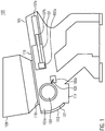
- the FIG. 1 shows a crushing device 100 according to the invention.
- the crushing device 100 comprises a housing 101, a rotor 103 and at least one counter blade 105.
- the or the counter blade 105 may / may be attached, for example, to a block-like counter-element unit 105b. It is understood that more than one counter-blade 105 can be used.
- Material to be comminuted for example plastic, is received in the comminuting device 100 through a funnel 109 and fed therefrom to the rotor 103 and the at least one counterblade 105.
- the material can for example be moved out of the hopper 109 in the direction of the rotor 103 by the gravitational force acting on the material.
- the funnel 109 is located in FIG. 1 on the housing 101.
- a suitable opening 119 is provided, through which the material from the hopper 109 can get into the interior 101a of the housing.
- the material is then comminuted by cooperation of the rotor 103 and the at least one counter knife 105.
- the area in which the rotor 103 and the counter knife or knives 105 cooperate and crush the material may also be referred to as the working area or comminution area of the comminution device 100.
- the shredded material may be dispensed through a screen 111 and collected outside the shredder 100 and removed, such as to be recycled.
- the FIG. 1 also shows a push button 107.
- the push button is provided in the housing 101 of the comminution device 100.
- the pusher 107 is movable so that he pushes the material to be crushed in the direction of the rotor 103 and the or the counter blade 105. The material to be shredded is thus pressed by the pusher 107 toward or into the work area. This significantly increases the efficiency of the comminution process.
- FIG. 1 a hydraulic drive 107a, 107b and 107c of the post-presser 107 are shown.
- the reference numeral 107a denotes a Nachdrücker piston.
- Reference numeral 107b denotes a push rod piston rod.
- the reference numeral 107c denotes a hydraulic cylinder for hydraulic guidance and the piston rod 107b and for driving the pusher 107.
- the drive 107 may be formed mechanically or pneumatically or as a chain drive.
- a combination of mechanical and / or pneumatic and / or hydraulic elements and / or chain drive elements is possible.
- FIG. 1 is also a guide rail 115 sketched. It is understood that the guide rail 115 is sketched purely by way of example and also a plurality of guide rails can be used. Likewise, additionally or alternatively guide grooves can be used to guide the funnel 109.
- the funnel 109 in FIG. 1 is movably provided on the housing 101 so as to be able to be moved from a working position in the case of maintenance FIG. 1 is shown to be moved to a second position.
- the guide rail 115 makes it possible to move the hopper 109 guided on the housing 101. As a result, the movement of the funnel 109 from the first position, the working position, to the second position can be defined particularly well.
- the funnel 101 can be additionally secured via the guide rail 115, so that it can not come loose from the housing 101, ie from the housing surface, during the displacement.
- FIG. 1 It is shown by way of example that the replacer remains completely in the comminution device 100 at least during the comminution process. As a result, a particularly compact device 100 can be provided.
- a maintenance flap 113 is shown, which is provided on the side of the housing on a wall 121 of the housing 101.
- This service door may provide additional lateral access to the interior 101a and rotor 103. But it can also be provided no maintenance flap 113 in the device and the wall 121 of the housing 101 may be provided as a normal housing wall without opening.
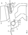
- FIG. 2 are the same elements with the same reference numerals as in the FIG. 1 designated.
- the hopper 109 of the crushing device 100 is shown such that the hopper 109 is in the second position.
- the crushing device 100 is thereby in a position suitable for maintenance or cleaning of the device.
- the inner space 101a of the housing 101, and in particular the working area of the rotor 103 and of the counter knife 105, is thus freely accessible from outside.
- the opening 119 of the work area and thus the rotor 103 and the or the counter blade 105 can be achieved directly in a simple manner to perform a maintenance and or cleaning in this area can.
- hopper 109 is coupled to pusher 107.
- a coupling element or coupling unit 117 is shown that provides the coupling between presser 107 and hopper 109.
- the coupling of presser 107 and hopper 109 by means of the coupling element 117 can be made manually in the simplest case. But there are also other coupling options conceivable, such as an electromagnetic coupling or a hydraulic coupling. Due to the coupling of the funnel 109 with the post-presser 107, the drive 107a, 107b, 107c of the post-presser 107 can also move the funnel 109 practically together with the post-presser 107.
- the movement of the presser 107 and the hopper 109 in this example takes place in the same direction.
- the hopper 109 is in the embodiment of the FIGS. 1 and 2 guided on at least one guide rail. It should be understood that proper control may control the movement of the pricker 107 and hopper 109.
- FIG. 2 Furthermore, the additional, optional maintenance flap 113 is shown in an open position, so that a lateral access via the housing wall 121 is possible.
- the hopper 109 has a separate drive, whereby the hopper 109 and the Nachdrücker 107 are independently driven.
- the comminution device is shown as a single-shaft shredder with a rotor 103 and counter-blade 105 statically formed on an opposed blade block 105b.
- the present invention can also be applied to two or more shaft shredders with more than one rotor.
- the crushing area, so the rotors by moving the funnel on or opposite the housing for maintenance in a simple manner can be achieved.
Landscapes
- Engineering & Computer Science (AREA)
- Food Science & Technology (AREA)
- Crushing And Pulverization Processes (AREA)
Priority Applications (6)
| Application Number | Priority Date | Filing Date | Title |
|---|---|---|---|
| PL13187384T PL2857103T3 (pl) | 2013-10-04 | 2013-10-04 | Urządzenie rozdrabniające |
| EP13187384.6A EP2857103B1 (de) | 2013-10-04 | 2013-10-04 | Zerkleinerungsvorrichtung |
| US14/497,862 US9968939B2 (en) | 2013-10-04 | 2014-09-26 | Shredding device |
| CA 2865403 CA2865403A1 (en) | 2013-10-04 | 2014-09-26 | Shredding device |
| CN201410513783.3A CN104668059B (zh) | 2013-10-04 | 2014-09-29 | 切碎装置 |
| BR102014024568-5A BR102014024568B1 (pt) | 2013-10-04 | 2014-10-01 | dispositivo triturador |
Applications Claiming Priority (1)
| Application Number | Priority Date | Filing Date | Title |
|---|---|---|---|
| EP13187384.6A EP2857103B1 (de) | 2013-10-04 | 2013-10-04 | Zerkleinerungsvorrichtung |
Publications (2)
| Publication Number | Publication Date |
|---|---|
| EP2857103A1 EP2857103A1 (de) | 2015-04-08 |
| EP2857103B1 true EP2857103B1 (de) | 2019-01-16 |
Family
ID=49303817
Family Applications (1)
| Application Number | Title | Priority Date | Filing Date |
|---|---|---|---|
| EP13187384.6A Active EP2857103B1 (de) | 2013-10-04 | 2013-10-04 | Zerkleinerungsvorrichtung |
Country Status (6)
| Country | Link |
|---|---|
| US (1) | US9968939B2 (pl) |
| EP (1) | EP2857103B1 (pl) |
| CN (1) | CN104668059B (pl) |
| BR (1) | BR102014024568B1 (pl) |
| CA (1) | CA2865403A1 (pl) |
| PL (1) | PL2857103T3 (pl) |
Families Citing this family (12)
| Publication number | Priority date | Publication date | Assignee | Title |
|---|---|---|---|---|
| ITUB20152420A1 (it) * | 2015-07-23 | 2017-01-23 | Colombo Giovanni S R L | Mulino frantumatore e metodo di frantumazione di rifiuti |
| CN105397940A (zh) * | 2015-12-17 | 2016-03-16 | 平湖市永光机械配件有限公司 | 一种精细粉碎机的转子轴芯 |
| CN105903742A (zh) * | 2016-04-18 | 2016-08-31 | 江南大学 | 餐厨垃圾预处理用处理设备及处理方法 |
| CA2960677C (en) * | 2016-04-28 | 2022-04-12 | Gerard DEVLOO | Canola seed sample crusher |
| CN106436403B (zh) * | 2016-10-09 | 2017-12-05 | 中山市为客包装制品有限公司 | 一种碎纸方法 |
| PL3437741T3 (pl) * | 2017-08-03 | 2026-03-02 | Manuel Lindner | Urządzenie rozdrabniające z regulowanym samoczynnym wciąganiem |
| ES2767682T3 (es) * | 2017-08-23 | 2020-06-18 | Untha Shredding Tech Gmbh | Dispositivo de trituración para triturar material |
| CN110080228A (zh) * | 2019-05-30 | 2019-08-02 | 三一汽车制造有限公司 | 泵送装置和管桩泵 |
| CN110919922A (zh) * | 2019-12-06 | 2020-03-27 | 株洲瑞尔泰机电科技有限公司 | 一种用于塑胶制品制造用的废料处理装置 |
| DE102020114510B3 (de) * | 2020-05-29 | 2021-09-30 | Vecoplan Ag | Zerkleinerungsvorrichtung umfassend eine Vorschubeinrichtung mit einer elektromotorischen Antriebseinrichtung |
| IT202200013219A1 (it) | 2022-06-22 | 2023-12-22 | Tecnofer Ecoimpianti S R L | Apparecchiatura di triturazione monoalbero perfezionata |
| CN117900008B (zh) * | 2024-03-20 | 2024-05-24 | 新乡市东振机械制造有限公司 | 一种建筑工程用固废破碎筛分机及其使用方法 |
Citations (2)
| Publication number | Priority date | Publication date | Assignee | Title |
|---|---|---|---|---|
| US3756519A (en) * | 1971-08-18 | 1973-09-04 | Entoleter | Novel granulating apparatus of modulator construction |
| US20100176233A1 (en) * | 2007-06-08 | 2010-07-15 | Satrind S.P.A. | Waste shredder comprising at least two rotors |
Family Cites Families (19)
| Publication number | Priority date | Publication date | Assignee | Title |
|---|---|---|---|---|
| US4043514A (en) * | 1976-03-16 | 1977-08-23 | Conair, Inc. | Comminution device |
| US4394984A (en) * | 1981-01-05 | 1983-07-26 | Polar Bear, Inc. | Ice block loading mechanism for an ice shaving machine |
| US5273218A (en) * | 1990-08-20 | 1993-12-28 | Burns Leslie L | Falcon hog |
| SE469926B (sv) * | 1992-09-16 | 1993-10-11 | Meltic Ab | Anordning vid en granuleringskvarn |
| US5695134A (en) * | 1996-04-10 | 1997-12-09 | Williams; Robert M. | Material reducing hammer mill with internal air circulating fan |
| DE19700808A1 (de) * | 1997-01-13 | 1998-07-16 | Lindemann Maschfab Gmbh | Rotorschere zum Zerkleinern von insbesondere sperrigen Abfällen mit einem Schneidrotor und einem feststehenden Gegenmesser |
| JPH10290940A (ja) * | 1997-04-18 | 1998-11-04 | Fuji Car Mfg Co Ltd | ごみの破砕選別処理装置 |
| US5988544A (en) * | 1998-10-08 | 1999-11-23 | Williams, Jr.; Robert M. | Rotary grinder cutting block |
| US6405949B1 (en) * | 1998-10-28 | 2002-06-18 | Stephen B. Maguire | Shuttle granulator |
| US6773545B2 (en) * | 2000-12-26 | 2004-08-10 | Kimberly-Clark Worldwide, Inc. | Method of forming and metering fluff pulp |
| CN2808298Y (zh) * | 2005-06-03 | 2006-08-23 | 东莞钜邦机电有限公司 | 一种强力粉碎机 |
| TWM314070U (en) * | 2006-11-30 | 2007-06-21 | Michilin Prosperity Co Ltd | Safety plate for paper feeding of movable shredder machine |
| CN201002039Y (zh) | 2007-01-11 | 2008-01-09 | 世庆实业股份有限公司 | 碎纸机的活动式入纸口盖板 |
| US7578463B2 (en) * | 2007-03-13 | 2009-08-25 | Sotsky George R | Modular Rotary Grinder |
| DE202010014764U1 (de) * | 2010-10-31 | 2012-02-01 | Weima Maschinenbau Gmbh | Zerkleinerungsmaschine |
| DE102012006650A1 (de) * | 2011-06-04 | 2012-12-06 | Weima Maschinenbau Gmbh | Zerkleinerungsvorrichtung |
| EP2749360A4 (en) * | 2011-08-22 | 2015-03-25 | Kyoritsu Industry Co Ltd | SYSTEM WITH A TRENCH UNIT |
| WO2013167497A2 (de) * | 2012-05-07 | 2013-11-14 | Erdmann Gmbh & Co. Kg | Zerkleinerungsmaschine |
| CN103316749A (zh) | 2013-06-24 | 2013-09-25 | 四川治源环保成套设备有限责任公司 | 一种垃圾粉碎机 |
-
2013
- 2013-10-04 EP EP13187384.6A patent/EP2857103B1/de active Active
- 2013-10-04 PL PL13187384T patent/PL2857103T3/pl unknown
-
2014
- 2014-09-26 CA CA 2865403 patent/CA2865403A1/en not_active Abandoned
- 2014-09-26 US US14/497,862 patent/US9968939B2/en active Active
- 2014-09-29 CN CN201410513783.3A patent/CN104668059B/zh active Active
- 2014-10-01 BR BR102014024568-5A patent/BR102014024568B1/pt active IP Right Grant
Patent Citations (2)
| Publication number | Priority date | Publication date | Assignee | Title |
|---|---|---|---|---|
| US3756519A (en) * | 1971-08-18 | 1973-09-04 | Entoleter | Novel granulating apparatus of modulator construction |
| US20100176233A1 (en) * | 2007-06-08 | 2010-07-15 | Satrind S.P.A. | Waste shredder comprising at least two rotors |
Also Published As
| Publication number | Publication date |
|---|---|
| PL2857103T3 (pl) | 2019-07-31 |
| CA2865403A1 (en) | 2015-04-04 |
| CN104668059B (zh) | 2018-05-08 |
| EP2857103A1 (de) | 2015-04-08 |
| US20150129697A1 (en) | 2015-05-14 |
| US9968939B2 (en) | 2018-05-15 |
| BR102014024568A2 (pt) | 2015-12-15 |
| CN104668059A (zh) | 2015-06-03 |
| BR102014024568B1 (pt) | 2020-12-22 |
Similar Documents
| Publication | Publication Date | Title |
|---|---|---|
| EP2857103A1 (de) | Zerkleinerungsvorrichtung | |
| DE19642232C2 (de) | Zerkleinerungs- und Emulgierautomat | |
| EP2218508A1 (de) | Zerkleinerungsvorrichtung | |
| DE102009060523A1 (de) | Zerkleinerungsvorrichtung mit Gegenmessereinrichtung | |
| EP1903102B1 (de) | Vorrichtung zur Förderung von Biomassematerialien | |
| DE102014216720A1 (de) | Zerkleinerungsmaschine zur Zerkleinerung eines Produkts | |
| EP1731223B1 (de) | Zerkleinerungsvorrichtung | |
| DE19708185C2 (de) | Verfahren und Einrichtung zum Beschicken und Betreiben einer Anlage zum Zerkleinern von recycelbaren Alt-Gütern | |
| EP2857101B1 (de) | Zerkleinerungsvorrichtung mit Wartungsklappe | |
| EP3437741B1 (de) | Zerkleinerungsvorrichtung mit regelbarem selbsteinzug | |
| EP2374544B1 (de) | Vorrichtung zum Zerkleinern von kompostierbarem Material | |
| EP2065091B1 (de) | Materialzerkleinerer | |
| AT398712B (de) | Restholzzerkleinerungsmaschine | |
| EP3215273B1 (de) | Vernichtung von beschriftetem papier | |
| DE102009020712A1 (de) | Vorrichtung zum Bearbeiten von Aufgabegut mit einem Rotor-Stator-System | |
| EP2599554A2 (de) | Vorrichtung zum Zerkleinern von Aufgabegut | |
| AT511382B1 (de) | Rotorschere | |
| EP2674222B1 (de) | Vorrichtung zum Zerkleinern von stückigen Abfällen | |
| DE102012006650A1 (de) | Zerkleinerungsvorrichtung | |
| DE202010014692U1 (de) | Vorrichtung zum Zerkleinern von schüttfähigem Aufgabegut | |
| EP0605382B1 (de) | Vorrichtung zum Zerkleinern von Abfällen | |
| DE19718614C1 (de) | Zerkleinerungsmaschine für sperrige Gegenstände | |
| DE19514951C2 (de) | Mobiler Abfall-Zerkleinerer | |
| DE202007006712U1 (de) | Schrauben-Nachdrückeinrichtung für Zerkleinerungseinrichtung | |
| EP2394742A1 (de) | Zerkleinerungsmaschine |
Legal Events
| Date | Code | Title | Description |
|---|---|---|---|
| PUAI | Public reference made under article 153(3) epc to a published international application that has entered the european phase |
Free format text: ORIGINAL CODE: 0009012 |
|
| 17P | Request for examination filed |
Effective date: 20131004 |
|
| AK | Designated contracting states |
Kind code of ref document: A1 Designated state(s): AL AT BE BG CH CY CZ DE DK EE ES FI FR GB GR HR HU IE IS IT LI LT LU LV MC MK MT NL NO PL PT RO RS SE SI SK SM TR |
|
| AX | Request for extension of the european patent |
Extension state: BA ME |
|
| R17P | Request for examination filed (corrected) |
Effective date: 20151001 |
|
| RBV | Designated contracting states (corrected) |
Designated state(s): AL AT BE BG CH CY CZ DE DK EE ES FI FR GB GR HR HU IE IS IT LI LT LU LV MC MK MT NL NO PL PT RO RS SE SI SK SM TR |
|
| STAA | Information on the status of an ep patent application or granted ep patent |
Free format text: STATUS: EXAMINATION IS IN PROGRESS |
|
| RAP1 | Party data changed (applicant data changed or rights of an application transferred) |
Owner name: LINDNER, MANUEL |
|
| 17Q | First examination report despatched |
Effective date: 20170925 |
|
| RIC1 | Information provided on ipc code assigned before grant |
Ipc: B02C 13/286 20060101ALI20180627BHEP Ipc: B02C 18/18 20060101ALI20180627BHEP Ipc: B02C 18/22 20060101AFI20180627BHEP |
|
| GRAP | Despatch of communication of intention to grant a patent |
Free format text: ORIGINAL CODE: EPIDOSNIGR1 |
|
| STAA | Information on the status of an ep patent application or granted ep patent |
Free format text: STATUS: GRANT OF PATENT IS INTENDED |
|
| INTG | Intention to grant announced |
Effective date: 20180803 |
|
| GRAS | Grant fee paid |
Free format text: ORIGINAL CODE: EPIDOSNIGR3 |
|
| GRAA | (expected) grant |
Free format text: ORIGINAL CODE: 0009210 |
|
| STAA | Information on the status of an ep patent application or granted ep patent |
Free format text: STATUS: THE PATENT HAS BEEN GRANTED |
|
| AK | Designated contracting states |
Kind code of ref document: B1 Designated state(s): AL AT BE BG CH CY CZ DE DK EE ES FI FR GB GR HR HU IE IS IT LI LT LU LV MC MK MT NL NO PL PT RO RS SE SI SK SM TR |
|
| REG | Reference to a national code |
Ref country code: GB Ref legal event code: FG4D Free format text: NOT ENGLISH |
|
| REG | Reference to a national code |
Ref country code: CH Ref legal event code: EP |
|
| REG | Reference to a national code |
Ref country code: IE Ref legal event code: FG4D Free format text: LANGUAGE OF EP DOCUMENT: GERMAN |
|
| REG | Reference to a national code |
Ref country code: DE Ref legal event code: R096 Ref document number: 502013012057 Country of ref document: DE |
|
| REG | Reference to a national code |
Ref country code: AT Ref legal event code: REF Ref document number: 1089287 Country of ref document: AT Kind code of ref document: T Effective date: 20190215 |
|
| REG | Reference to a national code |
Ref country code: SE Ref legal event code: TRGR |
|
| REG | Reference to a national code |
Ref country code: NL Ref legal event code: MP Effective date: 20190116 |
|
| REG | Reference to a national code |
Ref country code: LT Ref legal event code: MG4D |
|
| PG25 | Lapsed in a contracting state [announced via postgrant information from national office to epo] |
Ref country code: NL Free format text: LAPSE BECAUSE OF FAILURE TO SUBMIT A TRANSLATION OF THE DESCRIPTION OR TO PAY THE FEE WITHIN THE PRESCRIBED TIME-LIMIT Effective date: 20190116 |
|
| PG25 | Lapsed in a contracting state [announced via postgrant information from national office to epo] |
Ref country code: LT Free format text: LAPSE BECAUSE OF FAILURE TO SUBMIT A TRANSLATION OF THE DESCRIPTION OR TO PAY THE FEE WITHIN THE PRESCRIBED TIME-LIMIT Effective date: 20190116 Ref country code: ES Free format text: LAPSE BECAUSE OF FAILURE TO SUBMIT A TRANSLATION OF THE DESCRIPTION OR TO PAY THE FEE WITHIN THE PRESCRIBED TIME-LIMIT Effective date: 20190116 Ref country code: FI Free format text: LAPSE BECAUSE OF FAILURE TO SUBMIT A TRANSLATION OF THE DESCRIPTION OR TO PAY THE FEE WITHIN THE PRESCRIBED TIME-LIMIT Effective date: 20190116 Ref country code: PT Free format text: LAPSE BECAUSE OF FAILURE TO SUBMIT A TRANSLATION OF THE DESCRIPTION OR TO PAY THE FEE WITHIN THE PRESCRIBED TIME-LIMIT Effective date: 20190516 Ref country code: NO Free format text: LAPSE BECAUSE OF FAILURE TO SUBMIT A TRANSLATION OF THE DESCRIPTION OR TO PAY THE FEE WITHIN THE PRESCRIBED TIME-LIMIT Effective date: 20190416 |
|
| PG25 | Lapsed in a contracting state [announced via postgrant information from national office to epo] |
Ref country code: BG Free format text: LAPSE BECAUSE OF FAILURE TO SUBMIT A TRANSLATION OF THE DESCRIPTION OR TO PAY THE FEE WITHIN THE PRESCRIBED TIME-LIMIT Effective date: 20190416 Ref country code: LV Free format text: LAPSE BECAUSE OF FAILURE TO SUBMIT A TRANSLATION OF THE DESCRIPTION OR TO PAY THE FEE WITHIN THE PRESCRIBED TIME-LIMIT Effective date: 20190116 Ref country code: IS Free format text: LAPSE BECAUSE OF FAILURE TO SUBMIT A TRANSLATION OF THE DESCRIPTION OR TO PAY THE FEE WITHIN THE PRESCRIBED TIME-LIMIT Effective date: 20190516 Ref country code: RS Free format text: LAPSE BECAUSE OF FAILURE TO SUBMIT A TRANSLATION OF THE DESCRIPTION OR TO PAY THE FEE WITHIN THE PRESCRIBED TIME-LIMIT Effective date: 20190116 Ref country code: GR Free format text: LAPSE BECAUSE OF FAILURE TO SUBMIT A TRANSLATION OF THE DESCRIPTION OR TO PAY THE FEE WITHIN THE PRESCRIBED TIME-LIMIT Effective date: 20190417 Ref country code: HR Free format text: LAPSE BECAUSE OF FAILURE TO SUBMIT A TRANSLATION OF THE DESCRIPTION OR TO PAY THE FEE WITHIN THE PRESCRIBED TIME-LIMIT Effective date: 20190116 |
|
| REG | Reference to a national code |
Ref country code: DE Ref legal event code: R097 Ref document number: 502013012057 Country of ref document: DE |
|
| PG25 | Lapsed in a contracting state [announced via postgrant information from national office to epo] |
Ref country code: AL Free format text: LAPSE BECAUSE OF FAILURE TO SUBMIT A TRANSLATION OF THE DESCRIPTION OR TO PAY THE FEE WITHIN THE PRESCRIBED TIME-LIMIT Effective date: 20190116 Ref country code: CZ Free format text: LAPSE BECAUSE OF FAILURE TO SUBMIT A TRANSLATION OF THE DESCRIPTION OR TO PAY THE FEE WITHIN THE PRESCRIBED TIME-LIMIT Effective date: 20190116 Ref country code: SK Free format text: LAPSE BECAUSE OF FAILURE TO SUBMIT A TRANSLATION OF THE DESCRIPTION OR TO PAY THE FEE WITHIN THE PRESCRIBED TIME-LIMIT Effective date: 20190116 Ref country code: RO Free format text: LAPSE BECAUSE OF FAILURE TO SUBMIT A TRANSLATION OF THE DESCRIPTION OR TO PAY THE FEE WITHIN THE PRESCRIBED TIME-LIMIT Effective date: 20190116 Ref country code: DK Free format text: LAPSE BECAUSE OF FAILURE TO SUBMIT A TRANSLATION OF THE DESCRIPTION OR TO PAY THE FEE WITHIN THE PRESCRIBED TIME-LIMIT Effective date: 20190116 Ref country code: EE Free format text: LAPSE BECAUSE OF FAILURE TO SUBMIT A TRANSLATION OF THE DESCRIPTION OR TO PAY THE FEE WITHIN THE PRESCRIBED TIME-LIMIT Effective date: 20190116 |
|
| PLBE | No opposition filed within time limit |
Free format text: ORIGINAL CODE: 0009261 |
|
| STAA | Information on the status of an ep patent application or granted ep patent |
Free format text: STATUS: NO OPPOSITION FILED WITHIN TIME LIMIT |
|
| PG25 | Lapsed in a contracting state [announced via postgrant information from national office to epo] |
Ref country code: SM Free format text: LAPSE BECAUSE OF FAILURE TO SUBMIT A TRANSLATION OF THE DESCRIPTION OR TO PAY THE FEE WITHIN THE PRESCRIBED TIME-LIMIT Effective date: 20190116 |
|
| 26N | No opposition filed |
Effective date: 20191017 |
|
| PG25 | Lapsed in a contracting state [announced via postgrant information from national office to epo] |
Ref country code: SI Free format text: LAPSE BECAUSE OF FAILURE TO SUBMIT A TRANSLATION OF THE DESCRIPTION OR TO PAY THE FEE WITHIN THE PRESCRIBED TIME-LIMIT Effective date: 20190116 |
|
| PG25 | Lapsed in a contracting state [announced via postgrant information from national office to epo] |
Ref country code: TR Free format text: LAPSE BECAUSE OF FAILURE TO SUBMIT A TRANSLATION OF THE DESCRIPTION OR TO PAY THE FEE WITHIN THE PRESCRIBED TIME-LIMIT Effective date: 20190116 |
|
| PG25 | Lapsed in a contracting state [announced via postgrant information from national office to epo] |
Ref country code: MC Free format text: LAPSE BECAUSE OF FAILURE TO SUBMIT A TRANSLATION OF THE DESCRIPTION OR TO PAY THE FEE WITHIN THE PRESCRIBED TIME-LIMIT Effective date: 20190116 |
|
| REG | Reference to a national code |
Ref country code: CH Ref legal event code: PL |
|
| PG25 | Lapsed in a contracting state [announced via postgrant information from national office to epo] |
Ref country code: LI Free format text: LAPSE BECAUSE OF NON-PAYMENT OF DUE FEES Effective date: 20191031 Ref country code: LU Free format text: LAPSE BECAUSE OF NON-PAYMENT OF DUE FEES Effective date: 20191004 Ref country code: CH Free format text: LAPSE BECAUSE OF NON-PAYMENT OF DUE FEES Effective date: 20191031 |
|
| REG | Reference to a national code |
Ref country code: BE Ref legal event code: MM Effective date: 20191031 |
|
| PG25 | Lapsed in a contracting state [announced via postgrant information from national office to epo] |
Ref country code: BE Free format text: LAPSE BECAUSE OF NON-PAYMENT OF DUE FEES Effective date: 20191031 |
|
| GBPC | Gb: european patent ceased through non-payment of renewal fee |
Effective date: 20191004 |
|
| PG25 | Lapsed in a contracting state [announced via postgrant information from national office to epo] |
Ref country code: IE Free format text: LAPSE BECAUSE OF NON-PAYMENT OF DUE FEES Effective date: 20191004 Ref country code: GB Free format text: LAPSE BECAUSE OF NON-PAYMENT OF DUE FEES Effective date: 20191004 Ref country code: FR Free format text: LAPSE BECAUSE OF NON-PAYMENT OF DUE FEES Effective date: 20191031 |
|
| PG25 | Lapsed in a contracting state [announced via postgrant information from national office to epo] |
Ref country code: CY Free format text: LAPSE BECAUSE OF FAILURE TO SUBMIT A TRANSLATION OF THE DESCRIPTION OR TO PAY THE FEE WITHIN THE PRESCRIBED TIME-LIMIT Effective date: 20190116 |
|
| PG25 | Lapsed in a contracting state [announced via postgrant information from national office to epo] |
Ref country code: MT Free format text: LAPSE BECAUSE OF FAILURE TO SUBMIT A TRANSLATION OF THE DESCRIPTION OR TO PAY THE FEE WITHIN THE PRESCRIBED TIME-LIMIT Effective date: 20190116 Ref country code: HU Free format text: LAPSE BECAUSE OF FAILURE TO SUBMIT A TRANSLATION OF THE DESCRIPTION OR TO PAY THE FEE WITHIN THE PRESCRIBED TIME-LIMIT; INVALID AB INITIO Effective date: 20131004 |
|
| PG25 | Lapsed in a contracting state [announced via postgrant information from national office to epo] |
Ref country code: MK Free format text: LAPSE BECAUSE OF FAILURE TO SUBMIT A TRANSLATION OF THE DESCRIPTION OR TO PAY THE FEE WITHIN THE PRESCRIBED TIME-LIMIT Effective date: 20190116 |
|
| PGFP | Annual fee paid to national office [announced via postgrant information from national office to epo] |
Ref country code: DE Payment date: 20251029 Year of fee payment: 13 |
|
| PGFP | Annual fee paid to national office [announced via postgrant information from national office to epo] |
Ref country code: AT Payment date: 20251023 Year of fee payment: 13 |
|
| PGFP | Annual fee paid to national office [announced via postgrant information from national office to epo] |
Ref country code: IT Payment date: 20251030 Year of fee payment: 13 |
|
| PGFP | Annual fee paid to national office [announced via postgrant information from national office to epo] |
Ref country code: SE Payment date: 20251024 Year of fee payment: 13 |
|
| PGFP | Annual fee paid to national office [announced via postgrant information from national office to epo] |
Ref country code: PL Payment date: 20251002 Year of fee payment: 13 |