EP2856004B1 - Lampe mit einer flexiblen leiterplatte - Google Patents
Lampe mit einer flexiblen leiterplatte Download PDFInfo
- Publication number
- EP2856004B1 EP2856004B1 EP13733050.2A EP13733050A EP2856004B1 EP 2856004 B1 EP2856004 B1 EP 2856004B1 EP 13733050 A EP13733050 A EP 13733050A EP 2856004 B1 EP2856004 B1 EP 2856004B1
- Authority
- EP
- European Patent Office
- Prior art keywords
- lamp
- heat sink
- printed circuit
- flexible printed
- fpc
- Prior art date
- Legal status (The legal status is an assumption and is not a legal conclusion. Google has not performed a legal analysis and makes no representation as to the accuracy of the status listed.)
- Active
Links
- 239000007787 solid Substances 0.000 claims description 31
- 229910000679 solder Inorganic materials 0.000 claims description 5
- 239000000853 adhesive Substances 0.000 claims description 3
- 230000001070 adhesive effect Effects 0.000 claims description 3
- 238000009826 distribution Methods 0.000 description 9
- 230000001965 increasing effect Effects 0.000 description 9
- 238000004519 manufacturing process Methods 0.000 description 9
- 238000001816 cooling Methods 0.000 description 8
- 230000017525 heat dissipation Effects 0.000 description 6
- 239000000463 material Substances 0.000 description 4
- 150000003071 polychlorinated biphenyls Chemical class 0.000 description 4
- 239000000919 ceramic Substances 0.000 description 3
- 230000003287 optical effect Effects 0.000 description 3
- 238000005476 soldering Methods 0.000 description 3
- RYGMFSIKBFXOCR-UHFFFAOYSA-N Copper Chemical compound [Cu] RYGMFSIKBFXOCR-UHFFFAOYSA-N 0.000 description 2
- 238000010420 art technique Methods 0.000 description 2
- 229910052802 copper Inorganic materials 0.000 description 2
- 239000010949 copper Substances 0.000 description 2
- 230000002708 enhancing effect Effects 0.000 description 2
- 229920003207 poly(ethylene-2,6-naphthalate) Polymers 0.000 description 2
- 239000011112 polyethylene naphthalate Substances 0.000 description 2
- -1 polyethylene terephthalate Polymers 0.000 description 2
- 229920000139 polyethylene terephthalate Polymers 0.000 description 2
- 239000005020 polyethylene terephthalate Substances 0.000 description 2
- 206010052128 Glare Diseases 0.000 description 1
- FYYHWMGAXLPEAU-UHFFFAOYSA-N Magnesium Chemical compound [Mg] FYYHWMGAXLPEAU-UHFFFAOYSA-N 0.000 description 1
- 239000004642 Polyimide Substances 0.000 description 1
- 239000012790 adhesive layer Substances 0.000 description 1
- 239000004411 aluminium Substances 0.000 description 1
- 229910052782 aluminium Inorganic materials 0.000 description 1
- XAGFODPZIPBFFR-UHFFFAOYSA-N aluminium Chemical compound [Al] XAGFODPZIPBFFR-UHFFFAOYSA-N 0.000 description 1
- 230000000712 assembly Effects 0.000 description 1
- 238000000429 assembly Methods 0.000 description 1
- 238000005266 casting Methods 0.000 description 1
- 239000011248 coating agent Substances 0.000 description 1
- 238000000576 coating method Methods 0.000 description 1
- 239000003086 colorant Substances 0.000 description 1
- 230000007547 defect Effects 0.000 description 1
- 230000001419 dependent effect Effects 0.000 description 1
- 230000004313 glare Effects 0.000 description 1
- 239000011521 glass Substances 0.000 description 1
- 238000005286 illumination Methods 0.000 description 1
- 238000003754 machining Methods 0.000 description 1
- 239000011777 magnesium Substances 0.000 description 1
- 229910052749 magnesium Inorganic materials 0.000 description 1
- 229910052751 metal Inorganic materials 0.000 description 1
- 239000002184 metal Substances 0.000 description 1
- 238000003801 milling Methods 0.000 description 1
- 238000012986 modification Methods 0.000 description 1
- 230000004048 modification Effects 0.000 description 1
- 239000004033 plastic Substances 0.000 description 1
- 229920003023 plastic Polymers 0.000 description 1
- 229920001721 polyimide Polymers 0.000 description 1
- 239000000758 substrate Substances 0.000 description 1
- 239000012780 transparent material Substances 0.000 description 1
Images


Classifications
-
- H—ELECTRICITY
- H05—ELECTRIC TECHNIQUES NOT OTHERWISE PROVIDED FOR
- H05K—PRINTED CIRCUITS; CASINGS OR CONSTRUCTIONAL DETAILS OF ELECTRIC APPARATUS; MANUFACTURE OF ASSEMBLAGES OF ELECTRICAL COMPONENTS
- H05K1/00—Printed circuits
- H05K1/18—Printed circuits structurally associated with non-printed electric components
- H05K1/189—Printed circuits structurally associated with non-printed electric components characterised by the use of a flexible or folded printed circuit
-
- F—MECHANICAL ENGINEERING; LIGHTING; HEATING; WEAPONS; BLASTING
- F21—LIGHTING
- F21K—NON-ELECTRIC LIGHT SOURCES USING LUMINESCENCE; LIGHT SOURCES USING ELECTROCHEMILUMINESCENCE; LIGHT SOURCES USING CHARGES OF COMBUSTIBLE MATERIAL; LIGHT SOURCES USING SEMICONDUCTOR DEVICES AS LIGHT-GENERATING ELEMENTS; LIGHT SOURCES NOT OTHERWISE PROVIDED FOR
- F21K9/00—Light sources using semiconductor devices as light-generating elements, e.g. using light-emitting diodes [LED] or lasers
- F21K9/20—Light sources comprising attachment means
- F21K9/23—Retrofit light sources for lighting devices with a single fitting for each light source, e.g. for substitution of incandescent lamps with bayonet or threaded fittings
- F21K9/232—Retrofit light sources for lighting devices with a single fitting for each light source, e.g. for substitution of incandescent lamps with bayonet or threaded fittings specially adapted for generating an essentially omnidirectional light distribution, e.g. with a glass bulb
-
- F—MECHANICAL ENGINEERING; LIGHTING; HEATING; WEAPONS; BLASTING
- F21—LIGHTING
- F21K—NON-ELECTRIC LIGHT SOURCES USING LUMINESCENCE; LIGHT SOURCES USING ELECTROCHEMILUMINESCENCE; LIGHT SOURCES USING CHARGES OF COMBUSTIBLE MATERIAL; LIGHT SOURCES USING SEMICONDUCTOR DEVICES AS LIGHT-GENERATING ELEMENTS; LIGHT SOURCES NOT OTHERWISE PROVIDED FOR
- F21K99/00—Subject matter not provided for in other groups of this subclass
-
- F—MECHANICAL ENGINEERING; LIGHTING; HEATING; WEAPONS; BLASTING
- F21—LIGHTING
- F21V—FUNCTIONAL FEATURES OR DETAILS OF LIGHTING DEVICES OR SYSTEMS THEREOF; STRUCTURAL COMBINATIONS OF LIGHTING DEVICES WITH OTHER ARTICLES, NOT OTHERWISE PROVIDED FOR
- F21V23/00—Arrangement of electric circuit elements in or on lighting devices
- F21V23/003—Arrangement of electric circuit elements in or on lighting devices the elements being electronics drivers or controllers for operating the light source, e.g. for a LED array
- F21V23/007—Arrangement of electric circuit elements in or on lighting devices the elements being electronics drivers or controllers for operating the light source, e.g. for a LED array enclosed in a casing
- F21V23/009—Arrangement of electric circuit elements in or on lighting devices the elements being electronics drivers or controllers for operating the light source, e.g. for a LED array enclosed in a casing the casing being inside the housing of the lighting device
-
- F—MECHANICAL ENGINEERING; LIGHTING; HEATING; WEAPONS; BLASTING
- F21—LIGHTING
- F21V—FUNCTIONAL FEATURES OR DETAILS OF LIGHTING DEVICES OR SYSTEMS THEREOF; STRUCTURAL COMBINATIONS OF LIGHTING DEVICES WITH OTHER ARTICLES, NOT OTHERWISE PROVIDED FOR
- F21V29/00—Protecting lighting devices from thermal damage; Cooling or heating arrangements specially adapted for lighting devices or systems
- F21V29/50—Cooling arrangements
- F21V29/70—Cooling arrangements characterised by passive heat-dissipating elements, e.g. heat-sinks
- F21V29/83—Cooling arrangements characterised by passive heat-dissipating elements, e.g. heat-sinks the elements having apertures, ducts or channels, e.g. heat radiation holes
-
- F—MECHANICAL ENGINEERING; LIGHTING; HEATING; WEAPONS; BLASTING
- F21—LIGHTING
- F21V—FUNCTIONAL FEATURES OR DETAILS OF LIGHTING DEVICES OR SYSTEMS THEREOF; STRUCTURAL COMBINATIONS OF LIGHTING DEVICES WITH OTHER ARTICLES, NOT OTHERWISE PROVIDED FOR
- F21V29/00—Protecting lighting devices from thermal damage; Cooling or heating arrangements specially adapted for lighting devices or systems
- F21V29/85—Protecting lighting devices from thermal damage; Cooling or heating arrangements specially adapted for lighting devices or systems characterised by the material
- F21V29/89—Metals
-
- F—MECHANICAL ENGINEERING; LIGHTING; HEATING; WEAPONS; BLASTING
- F21—LIGHTING
- F21V—FUNCTIONAL FEATURES OR DETAILS OF LIGHTING DEVICES OR SYSTEMS THEREOF; STRUCTURAL COMBINATIONS OF LIGHTING DEVICES WITH OTHER ARTICLES, NOT OTHERWISE PROVIDED FOR
- F21V3/00—Globes; Bowls; Cover glasses
-
- F—MECHANICAL ENGINEERING; LIGHTING; HEATING; WEAPONS; BLASTING
- F21—LIGHTING
- F21V—FUNCTIONAL FEATURES OR DETAILS OF LIGHTING DEVICES OR SYSTEMS THEREOF; STRUCTURAL COMBINATIONS OF LIGHTING DEVICES WITH OTHER ARTICLES, NOT OTHERWISE PROVIDED FOR
- F21V3/00—Globes; Bowls; Cover glasses
- F21V3/02—Globes; Bowls; Cover glasses characterised by the shape
-
- F—MECHANICAL ENGINEERING; LIGHTING; HEATING; WEAPONS; BLASTING
- F21—LIGHTING
- F21K—NON-ELECTRIC LIGHT SOURCES USING LUMINESCENCE; LIGHT SOURCES USING ELECTROCHEMILUMINESCENCE; LIGHT SOURCES USING CHARGES OF COMBUSTIBLE MATERIAL; LIGHT SOURCES USING SEMICONDUCTOR DEVICES AS LIGHT-GENERATING ELEMENTS; LIGHT SOURCES NOT OTHERWISE PROVIDED FOR
- F21K9/00—Light sources using semiconductor devices as light-generating elements, e.g. using light-emitting diodes [LED] or lasers
- F21K9/60—Optical arrangements integrated in the light source, e.g. for improving the colour rendering index or the light extraction
-
- F—MECHANICAL ENGINEERING; LIGHTING; HEATING; WEAPONS; BLASTING
- F21—LIGHTING
- F21V—FUNCTIONAL FEATURES OR DETAILS OF LIGHTING DEVICES OR SYSTEMS THEREOF; STRUCTURAL COMBINATIONS OF LIGHTING DEVICES WITH OTHER ARTICLES, NOT OTHERWISE PROVIDED FOR
- F21V3/00—Globes; Bowls; Cover glasses
- F21V3/04—Globes; Bowls; Cover glasses characterised by materials, surface treatments or coatings
- F21V3/06—Globes; Bowls; Cover glasses characterised by materials, surface treatments or coatings characterised by the material
- F21V3/061—Globes; Bowls; Cover glasses characterised by materials, surface treatments or coatings characterised by the material the material being glass
- F21V3/0615—Globes; Bowls; Cover glasses characterised by materials, surface treatments or coatings characterised by the material the material being glass the material diffusing light, e.g. translucent glass
-
- F—MECHANICAL ENGINEERING; LIGHTING; HEATING; WEAPONS; BLASTING
- F21—LIGHTING
- F21V—FUNCTIONAL FEATURES OR DETAILS OF LIGHTING DEVICES OR SYSTEMS THEREOF; STRUCTURAL COMBINATIONS OF LIGHTING DEVICES WITH OTHER ARTICLES, NOT OTHERWISE PROVIDED FOR
- F21V3/00—Globes; Bowls; Cover glasses
- F21V3/04—Globes; Bowls; Cover glasses characterised by materials, surface treatments or coatings
- F21V3/06—Globes; Bowls; Cover glasses characterised by materials, surface treatments or coatings characterised by the material
- F21V3/062—Globes; Bowls; Cover glasses characterised by materials, surface treatments or coatings characterised by the material the material being plastics
- F21V3/0625—Globes; Bowls; Cover glasses characterised by materials, surface treatments or coatings characterised by the material the material being plastics the material diffusing light, e.g. translucent plastics
-
- F—MECHANICAL ENGINEERING; LIGHTING; HEATING; WEAPONS; BLASTING
- F21—LIGHTING
- F21Y—INDEXING SCHEME ASSOCIATED WITH SUBCLASSES F21K, F21L, F21S and F21V, RELATING TO THE FORM OR THE KIND OF THE LIGHT SOURCES OR OF THE COLOUR OF THE LIGHT EMITTED
- F21Y2107/00—Light sources with three-dimensionally disposed light-generating elements
- F21Y2107/40—Light sources with three-dimensionally disposed light-generating elements on the sides of polyhedrons, e.g. cubes or pyramids
-
- F—MECHANICAL ENGINEERING; LIGHTING; HEATING; WEAPONS; BLASTING
- F21—LIGHTING
- F21Y—INDEXING SCHEME ASSOCIATED WITH SUBCLASSES F21K, F21L, F21S and F21V, RELATING TO THE FORM OR THE KIND OF THE LIGHT SOURCES OR OF THE COLOUR OF THE LIGHT EMITTED
- F21Y2115/00—Light-generating elements of semiconductor light sources
- F21Y2115/10—Light-emitting diodes [LED]
-
- H—ELECTRICITY
- H05—ELECTRIC TECHNIQUES NOT OTHERWISE PROVIDED FOR
- H05K—PRINTED CIRCUITS; CASINGS OR CONSTRUCTIONAL DETAILS OF ELECTRIC APPARATUS; MANUFACTURE OF ASSEMBLAGES OF ELECTRICAL COMPONENTS
- H05K2201/00—Indexing scheme relating to printed circuits covered by H05K1/00
- H05K2201/10—Details of components or other objects attached to or integrated in a printed circuit board
- H05K2201/10007—Types of components
- H05K2201/10106—Light emitting diode [LED]
Definitions
- the present invention relates to lamps comprising solid state light sources, such as retrofit light emitting diode (LED) lamps, and in particular to LED lamps of the interdigitated type.
- solid state light sources such as retrofit light emitting diode (LED) lamps
- LED lamp design To obtain omnidirectional light distribution resembling the light distribution of an incandescent light bulb and to provide sufficient dissipation of heat generated by the LEDs and the driving electronics.
- WO 2010/058325 shows a bulb-type LED lamp having a bulb mounted on a socket. Inside the bulb, a plurality of LEDs are mounted on a printed circuit board (PCB), which is connected to cooling means.
- the cooling means extends from inside the bulb to the outer surface of the bulb, whereby the outer surface of the bulb is formed both by sub-areas of a light transmittable surface and the cooling means.
- the sub-areas and the cooling means are preferably arranged in an interdigitated (alternating) configuration.
- the cooling means and the light transmittable surface form the bulb outer surface, thereby improving heat dissipation from the LEDs as well as the omnidirectional light distribution.
- such lamps give rise to new manufacturing challenges due to the more complex interconnection between the driving electronics and the PCBs caused by their mutual orientation.
- the lamp comprises at least two solid state light sources, a envelope comprising a light transmittable surface adapted to transmit light from the solid state light sources and a heat sink (or cooling means) extending from inside the envelope to the outer surface of the envelope such that it divides the envelope into at least two compartments.
- the lamp further comprises a flexible printed circuit (FPC) at which the solid state light sources are mounted. The FPC is attached to the heat sink such that the solid state light sources are distributed in (both of) the compartments.
- FPC flexible printed circuit
- the interconnection structure (between the solid state light sources and the driving electronics) is less complex, which facilitates manufacturing and provides more space for the driving electronics.
- the manufacturing of the lamp is further facilitated (and manufacturing costs are reduced) because the need of milling the surfaces of the heat sink, at which surfaces the FPC is mounted, is reduced.
- such surfaces of the heat sink require very high flatness tolerances and therefore have to be milled to a certain flatness to prevent cracks in the PCBs (which typically comprise ceramic boards) which are mounted to the surfaces.
- Ceramic PCBs are stiff and brittle and may therefore crack if pressed down on an uneven surface with a concentrated force, e.g. exerted by a screw.
- the present invention is further advantageous in that the light distribution is improved, as the arrangement of the solid state light sources at the compartment walls (at the heat sink) and the light transmittable surface of the envelope provides a more omnidirectional spatial light distribution.
- the desired omnidirectional light distribution is hampered by the base plate (lower wall) at which the LEDs are mounted.
- the present invention is advantageous in that the heat dissipation capacity of the lamp is improved.
- the extension of the heat sink to the outer surface of the envelope increases the surface of the heat sink exposed to the ambient atmosphere.
- the flexibility of the FPC allows it to better conform to the shape of the heat sink, whereby it may have an increased area, as it may cover non-flat surfaces of the heat sink.
- An increased area of the FPC provides an increased heat transfer surface of the FPC to the heat sink, which further improves the heat dissipation from the solid state light sources.
- the increased heat transfer surface of the FPC makes the interface between the FPC and the heat sink less critical, thereby reducing the need of thermal interface material (TIM) between the FPC and the heat sink, which reduces manufacturing costs.
- TIM thermal interface material
- the present invention is further advantageous in that the circuits with the solid state light sources, and preferably the wirings for interconnecting the solid state light sources with the driving electronics, may be integrated to one assembly with the FPC.
- the FPC can be shaped and adapted to the inner structure of the lamp such that one portion of the FPC, which portion comprises at least one solid state light source, may be attached to the heat sink in one of the compartments, and another portion of the FPC, which portion also comprises at least one solid state light source, may be attached to the heat sink in another compartment.
- the portion of the FPC interconnecting the two portions may e.g. be bent over a wall or portion of the heat sink separating the compartments.
- the manufacturing, and in particular assembling, of the lamp is thus facilitated since the number of components to assemble may be reduced and the need of soldering (e.g. of wires to circuit boards) may be reduced. A reduced number of soldered connections also reduces the risk of solder defects.
- the present invention is further advantageous in that the FPC is thinner than conventional printed circuit types (e.g. FR4 or IMS) and therefore allows the solid state light sources to be positioned further from the light transmittable surface, which facilitates color mixing when solid state light sources of different colors are used, and makes the luminous intensity over angle more uniform, as the light transmittable surface is more homogeneously radiated.
- conventional printed circuit types e.g. FR4 or IMS
- the FPC may be a single piece FPC, which is advantageous in that the number of assemblies (or parts) in the lamp is reduced.
- the circuits with the solid state light sources, and preferably the wiring for connecting the solid state light sources to the driving electronics are integrated in a single FPC.
- the number of soldered connections is further reduced, as the single FPC reduces the need of soldered connections between the solid state light sources and the driving electronics.
- the FPC may include two or more FPC pieces.
- the FPC may comprise leg portions (or extensions) extending from a mid portion of the FPC and each leg portion may be arranged in one of the compartments.
- the FPC may e.g. comprise three leg portions if the lamp comprises three compartments such that one leg is arranged in each one of the compartments.
- the flexibility of the FPC allows the leg portions to be bent down into the different compartments.
- the mid portion may form a junction for the leg portions to which the wiring from the solid state light sources at each leg may gather.
- the present embodiment provides a convenient design of the FPC for fitting it into the different compartments and enabling it to be manufactured in a single piece.
- the FPC comprises an interconnection leg portion (or interconnection extension) adapted to be connected to the driving electronics of the lamp.
- the interconnection leg portion may form a part of the FPC (i.e. be an FPC portion) and comprise wiring connected to the solid state light sources.
- the end of the interconnection leg portion may comprise interconnection spots which may be soldered (or in another way connected) to the driving electronics.
- the present embodiment is advantageous in that it reduces the need of separate wiring, and thus also the number of soldered connections, for connecting the solid state light sources to the driving electronics.
- the FPC may cover a major part, such as at least 50 %, and preferably at least 80 %, and even more preferably at least 90%, of the heat sink surface (or heat sink compartment wall) inside the envelope, thereby increasing the heat transfer surface of the FPC and thus also the heat transfer interface between the FPC and the heat sink.
- the heat dissipating capacity of the lamp is improved and the need of TIM between the FPC and the heat sink is further reduced.
- the light transmittable surface may be divided into sub areas by the heat sink. Each sub area may be associated with one of the compartments.
- the light distribution of the lamp may be tuned e.g. via setting of the orientation of the sub areas and the associated sub group of solid state light sources.
- the sub areas and the heat sink may be arranged in an interdigitated (or alternating) configuration, which is advantageous in that the heat sink is spread (preferably continuously) over the envelope outer surface, thereby further enhancing the heat dissipation capacity.
- the interdigitated configuration also facilitates manufacturing as it facilitates mounting the light transmittable surface to the heat sink.
- the sub areas may form an integral light transmittable surface, thereby reducing the number of lamp parts, which facilitates assembly of the lamp.
- the heat sink may comprise recesses extending towards a longitudinal axis of the lamp (i.e. inwardly, towards the middle of the lamp). It will be appreciated that the longitudinal axis (or optical axis) of the lamp extends through a central end of a socket (or base or lower part) of the lamp and a central extremity of the envelope.
- the present embodiment is advantageous in that the outer surface area of the heat sink is increased, which improves the heat dissipation from the heat sink.
- the heat sink may be solid, i.e. without recesses, which facilitates manufacture (machining and casting) of the heat sink.
- the FPC may comprise a reflective solder resist, which is advantageous in that it increases the light output from the lamp, as the reflective solder resist then reflects light from the solid state light sources out of the lamp.
- the need of a separate reflector part is reduced, which reduces costs and complexity of the lamp.
- the FPC may be attached to the heat sink by means of an adhesive.
- an adhesive layer may be coated on the FPC and/or heat sink for the attachment of the FPC to the heat sink.
- the present embodiment is advantageous in that it reduces the need of a screw for attaching the FPC to the heat sink and thereby facilitates assembly.
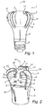
- the lamp 1 comprises a bulb 2, in which LEDs 9 (not shown in Figure 1 , but in Figures 2 and 3 ), or any other kind of solid state light sources, are arranged and a socket 6 adapted to be fitted in a lamp fitting.
- the socket 6 is mounted to bulb 2 such that a longitudinal axis 10 (or optical axis) of the lamp 1 extends through a central end of the socket 6 and a central extremity of the bulb 2.
- the lamp 1 further comprises a light transmittable (or transmissive) surface 3, which forms a part of the bulb 2 and is adapted to transmit light from the LEDs 9.
- the light transmittable surface 3 may be made of a transparent or semi-transparent material, such as glass (or any other ceramic) or plastics, and may preferably be diffuse (frosted) for reducing the risk of glare of the LEDs 9 and improving color mixing (if different colored LEDs are used), light homogeneity and light distribution over angle (IoA).
- the envelope is bulb-shaped and therefore also referred to as bulb.
- the invention is not restricted to envelopes that are bulb-shaped; each envelope with the required functionality falls under the scope of the present invention.
- the lamp 1 For cooling the LEDs 9 and the driving electronics (not shown), the lamp 1 comprises a heat sink 4 extending from inside the bulb 2 to the outer surface of the bulb 2 such that it divides the bulb 2 into a number of compartments 16 (shown in Figure 2 ). Accordingly, the walls of the enclosure defined by a compartment 16 are formed by the surfaces of the heat sink 4 and the light transmittable surface 3.
- the heat sink 4, and in particular the outer edges of the heat sink 4 walls, divides the light transmittable surface 3 into sub areas 17, which preferably may be integral and form a single piece of material.
- the sub areas 17 may extend from a mid portion of the light transmittable surface 3 (the mid portion being on top of the bulb 2).
- the sub areas 17 and the heat sink 4 may be arranged in an interdigitated (or forked) configuration, wherein the sub areas 17 and the heat sink 4 (or the outer edges of the heat sink 4) are alternately arranged. Together, the heat sink 4 and the light transmittable surface 3 form the outer surface of the bulb 2.
- the heat sink 4 may comprise recesses 8 extending towards the longitudinal axis 10 of the lamp 1 and the longitudinal direction of which may be substantially parallel with the longitudinal axis 10.
- the recesses 8 may thus form grooves with a concave form in the (outer surface of) the bulb 2.
- the lamp 1 may further comprise a bottom heat sink 5, which preferably may be made (casted) in the same piece of material as the heat sink 4 of the bulb 2, thereby reducing the number of parts in the lamp 1 and increasing the heat transfer from the bulb to the bottom heat sink 5.
- the bottom heat sink 5 and the heat sink 4 of the bulb 2 may be made as separate parts.
- the heat sink 4 and the bottom heat sink 5 are preferably made of metal with a thermal conductivity of 70-200W/mK, such as magnesium or aluminium, or any material having a thermal conductivity of at least 20W/mK.
- the design of the lamp 1, in particular with respect to the heat sink 4 (or cooling means), the light transmittable surface 3, the bulb 2 and the socket 6, may be made according to the disclosure of WO 2010/058325 , and in particular according to Figures 2A-3B and the corresponding part of the description of WO 2010/058325 , which disclosure hereby is incorporated by reference.
- the lamp 1 further comprises a FPC (flexible printed circuit) 7 at which the LEDs 9 are attached (e.g. by soldering).
- FPC 7 flexible printed circuit
- the FPC 7 is applied to the heat sink 4 of the lamp 1, and in figure 3 , the FPC 7 is shown in a plane, non-folded and non-applied state or, in other words, in a deployed state.
- the FPC 7 comprises a flexible substrate comprising e.g. PET (polyethylene terephthalate), PEN (polyethylene naphthalate) or PI (polyimide), at which the electric components, including wiring 14 (or copper tracks), shown in Figure 2 , and the LEDs 9, are applied.
- the wiring 14 is adapted to connect the LEDs 9 to the driving electronics.
- the FPC comprises a copper coating 18 (shown in Figure 3 ) with a thickness of about 35-100 ⁇ m, and preferably about 70 ⁇ m, for enhancing the heat dissipation from the FPC.
- the FPC may comprise a reflective (such as white) solder resist.
- the FPC 7 may preferably be made of a single piece comprising leg portions 12 and an interconnection leg portion 13 extending from a mid portion 11 (or junction portion) of the FPC 7.
- the LEDs 9 are mounted at the leg portions 12 and the wiring 14 extends from the LEDs 9 via the mid portion 11 to the interconnection leg portion 13.
- interconnection spots or pads 15 for connecting the FPC 7 to the driving electronics are arranged.
- the FPC is attached to the heat sink 4, preferably by an adhesive, such that each leg portion 12 is arranged in one of the compartments 16. Each leg portion 12 is thus bent over the upper edge of the heat sink 4 and the interconnection leg portion 13 is bent down into a compartment inside (in the middle of) the heat sink 4, in which compartment the driving electronics is arranged.
- the FPC 7 may cover a major part, such as at least 80%, of the heat sink surface inside the bulb 2, and preferably, each leg portion 12 may have approximately the same size (area) as the corresponding heat sink compartment wall (or surface) it is attached to (as illustrated in Figure 2 ) for providing largest possible heat transfer surface.
- the lamp 1 may comprise at least one (separate) reflector 20 arranged in at least one of the compartments, preferably such that the reflector covers the FPC 7 (with openings for the solid state light sources 9), as shown in Figure 4 .
- the FPC 7 may be arranged between the heat sink 4 and the reflector 20.
- the present embodiment is advantageous in that the FPC 7 is thinner than conventional PCB types (such as FR4 or IMS) and therefore requires less space between the reflector and the heats sink.
- conventional PCB types such as FR4 or IMS
- the wires soldered to the PCB absorb light and must therefore be covered by the reflector, which thus bulges into the optical chamber.
- a bulging reflector is disadvantageous in that it is more directly illuminated by the solid state light sources (due to its proximity to the solid state light sources). However, it is desirable that only light scattered back from the diffused light transmittable surface should be reflected by the reflector. With the present embodiment, such bulge in the reflector is not necessary since the FPB 7 is thinner and flatter than conventional PCB solutions. Hence, the direct illumination of the reflector 20 is reduced, which is advantageous in that it reduces reflection losses.
Landscapes
- Engineering & Computer Science (AREA)
- General Engineering & Computer Science (AREA)
- Microelectronics & Electronic Packaging (AREA)
- Physics & Mathematics (AREA)
- Optics & Photonics (AREA)
- Arrangement Of Elements, Cooling, Sealing, Or The Like Of Lighting Devices (AREA)
- Non-Portable Lighting Devices Or Systems Thereof (AREA)
Claims (9)
- Lampe (1), umfassend:- mindestens zwei Halbleiter-Lichtquellen (9);- eine Hülle (2), umfassend eine lichtübertragbare Oberfläche (3), die angepasst ist, um Licht von den Halbleiter-Lichtquellen zu übertragen;- einen Kühlkörper (4), der sich vom Inneren der Hülle zu der äußeren Oberfläche der Hülle erstreckt, so dass er die Hülle in mindestens zwei Kammern (16) teilt; und- eine flexible Leiterplatte (7), an der die Halbleiter-Lichtquellen angebracht sind,wobei die flexible Leiterplatte am Kühlkörper befestigt ist, so dass die Halbleiter-Lichtquellen in den Kammern verteilt sind, und
wobei die flexible Leiterplatte einen Verbindungsschenkelabschnitt (13) umfasst, der angepasst ist, um mit der Antriebselektronik der Lampe verbunden zu werden. - Lampe nach Anspruch 1, wobei die flexible Leiterplatte eine einstückige flexible Leiterplatte ist.
- Lampe nach Anspruch 1, wobei die flexible Leiterplatte Schenkelabschnitte (12) umfasst, die sich von einem mittleren Abschnitt (11) der flexiblen Leiterplatte erstrecken, und wobei jeder Schenkelabschnitt in einer der Kammern angeordnet ist.
- Lampe nach Anspruch 1, wobei die flexible Leiterplatte einen Großteil der Kühlkörperoberfläche im Inneren der Hülle bedeckt.
- Lampe nach Anspruch 1, wobei die lichtübertragbare Oberfläche von dem Kühlkörper in Teilbereiche (17) geteilt wird.
- Lampe nach Anspruch 5, wobei die Teilbereiche und der Kühlkörper in einer ineinander greifenden Konfiguration angeordnet sind.
- Lampe nach Anspruch 1, wobei der Kühlkörper Vertiefungen (8) umfasst, die sich zu einer Längsachse (10) der Lampe erstrecken.
- Lampe nach Anspruch 1, wobei die flexible Leiterplatte einen reflektierenden Lötstopplack umfasst.
- Lampe nach Anspruch 1, wobei die flexible Leiterplatte am Kühlkörper mittels eines Klebstoffs befestigt ist.
Applications Claiming Priority (2)
| Application Number | Priority Date | Filing Date | Title |
|---|---|---|---|
| US201261654991P | 2012-06-04 | 2012-06-04 | |
| PCT/IB2013/054230 WO2013182937A1 (en) | 2012-06-04 | 2013-05-22 | Lamp comprising a flexible printed circuit board |
Publications (2)
| Publication Number | Publication Date |
|---|---|
| EP2856004A1 EP2856004A1 (de) | 2015-04-08 |
| EP2856004B1 true EP2856004B1 (de) | 2016-09-14 |
Family
ID=48741429
Family Applications (1)
| Application Number | Title | Priority Date | Filing Date |
|---|---|---|---|
| EP13733050.2A Active EP2856004B1 (de) | 2012-06-04 | 2013-05-22 | Lampe mit einer flexiblen leiterplatte |
Country Status (7)
| Country | Link |
|---|---|
| US (1) | US10362679B2 (de) |
| EP (1) | EP2856004B1 (de) |
| JP (1) | JP6203833B2 (de) |
| CN (2) | CN103470970B (de) |
| DE (1) | DE102013105289A1 (de) |
| RU (1) | RU2648267C2 (de) |
| WO (1) | WO2013182937A1 (de) |
Families Citing this family (10)
| Publication number | Priority date | Publication date | Assignee | Title |
|---|---|---|---|---|
| US10362679B2 (en) * | 2012-06-04 | 2019-07-23 | Signify Holding B.V. | Lamp comprising a flexible printed circuit board |
| US10622405B2 (en) * | 2018-05-04 | 2020-04-14 | Lumileds Llc | Light fixture with dynamically controllable light distribution |
| US10821890B2 (en) | 2018-05-04 | 2020-11-03 | Lumileds Llc | Light engines with dynamically controllable light distribution |
| US10785847B2 (en) | 2018-05-04 | 2020-09-22 | Lumileds Llc | Light engines with dynamically controllable light distribution |
| US10943945B2 (en) | 2018-05-04 | 2021-03-09 | Lumileds Llc | Light fixture with dynamically controllable light distribution |
| US10750588B2 (en) | 2018-05-04 | 2020-08-18 | Lumileds Llc | Light fixture with dynamically controllable light distribution |
| US10872923B2 (en) | 2018-05-04 | 2020-12-22 | Lumileds Llc | Light engines with dynamically controllable light distribution |
| US10859757B2 (en) | 2018-05-04 | 2020-12-08 | Lumileds Llc | Light fixture with light guide and radially emitting LEDs |
| US10845529B2 (en) | 2018-05-04 | 2020-11-24 | Lumileds Llc | Light engines with dynamically controllable light distribution |
| EP4085219A1 (de) | 2020-01-02 | 2022-11-09 | Signify Holding B.V. | Beleuchtungsvorrichtung |
Family Cites Families (36)
| Publication number | Priority date | Publication date | Assignee | Title |
|---|---|---|---|---|
| US5890794A (en) * | 1996-04-03 | 1999-04-06 | Abtahi; Homayoon | Lighting units |
| CN2637885Y (zh) * | 2003-02-20 | 2004-09-01 | 高勇 | 发光面为曲面的led灯泡 |
| US7086756B2 (en) * | 2004-03-18 | 2006-08-08 | Lighting Science Group Corporation | Lighting element using electronically activated light emitting elements and method of making same |
| US7207695B2 (en) * | 2004-11-22 | 2007-04-24 | Osram Sylvania Inc. | LED lamp with LEDs on a heat conductive post and method of making the LED lamp |
| JP2006244725A (ja) | 2005-02-28 | 2006-09-14 | Atex Co Ltd | Led照明装置 |
| JP2007080351A (ja) * | 2005-09-13 | 2007-03-29 | Funai Electric Co Ltd | 光ディスク記録再生装置 |
| TW200821694A (en) * | 2006-11-01 | 2008-05-16 | Au Optronics Corp | Reflective light source device and manufacture method thereof |
| US7581856B2 (en) * | 2007-04-11 | 2009-09-01 | Tamkang University | High power LED lighting assembly incorporated with a heat dissipation module with heat pipe |
| FR2914984B1 (fr) | 2007-04-13 | 2013-11-08 | Valeo Vision | Support electronique flexible equipe, supportant au moins une diode electroluminescente, et procede de fabrication associe. |
| US7434964B1 (en) * | 2007-07-12 | 2008-10-14 | Fu Zhun Precision Industry (Shen Zhen) Co., Ltd. | LED lamp with a heat sink assembly |
| CN101360387B (zh) | 2007-08-03 | 2012-06-13 | 富葵精密组件(深圳)有限公司 | 柔性电路板基膜、柔性电路板基板及柔性电路板 |
| CA2636675C (en) * | 2007-08-13 | 2016-05-24 | Filipe P. Matias | Polarity tester for an electronic communication port |
| CN101424394B (zh) * | 2007-11-02 | 2010-09-08 | 富准精密工业(深圳)有限公司 | 散热装置及其应用的发光二极管灯具 |
| US7695162B2 (en) * | 2007-12-27 | 2010-04-13 | Fu Zhun Precision Industry (Shen Zhen) Co., Ltd. | LED lamp having a plurality of heat sinks |
| US8013501B2 (en) | 2008-06-04 | 2011-09-06 | Forever Bulb, Llc | LED-based light bulb device |
| CN101634441B (zh) | 2008-07-21 | 2011-03-16 | 奇力光电科技股份有限公司 | 发光二极管光源模块及应用其的背光模块、液晶显示器 |
| KR100883346B1 (ko) * | 2008-08-08 | 2009-02-12 | 김현민 | 패널형 led 조명장치 |
| KR20100044632A (ko) | 2008-10-22 | 2010-04-30 | 주식회사 루미시스 | 엘이디 조명장치용 회로모듈 및 그를 포함하는 엘이디 조명장치 |
| JP4642129B2 (ja) * | 2008-11-06 | 2011-03-02 | ローム株式会社 | Ledランプ |
| US8314537B2 (en) | 2008-11-18 | 2012-11-20 | Koninklijke Philips Electronics N.V. | Electric lamp |
| EP2399070B1 (de) * | 2009-02-17 | 2017-08-23 | Epistar Corporation | Led-glühbirnen zur raumbeleuchtung |
| TW201100711A (en) | 2009-06-30 | 2011-01-01 | Power Light Tech Co Ltd | Light emitting diode light source assembly with heat dissipation base |
| US9030120B2 (en) * | 2009-10-20 | 2015-05-12 | Cree, Inc. | Heat sinks and lamp incorporating same |
| JP2011192930A (ja) | 2010-03-16 | 2011-09-29 | Toshiba Corp | 基板、基板の製造方法及び灯具 |
| US8690386B2 (en) * | 2010-04-16 | 2014-04-08 | Chun-Hsien Lee | LED bulb |
| JP5662059B2 (ja) | 2010-06-04 | 2015-01-28 | パナソニックIpマネジメント株式会社 | Ledランプ |
| US8596821B2 (en) * | 2010-06-08 | 2013-12-03 | Cree, Inc. | LED light bulbs |
| RU99657U1 (ru) * | 2010-08-12 | 2010-11-20 | Игорь Иннокентьевич Жойдик | Светодиодная лампа |
| CN101893181B (zh) * | 2010-08-17 | 2013-03-20 | 史杰 | 一种高效led灯泡 |
| US8272762B2 (en) * | 2010-09-28 | 2012-09-25 | Lighting Science Group Corporation | LED luminaire |
| TWM412319U (en) * | 2010-11-01 | 2011-09-21 | Parlux Optoelectronics Corp | LED illumination device |
| EP2450613B1 (de) * | 2010-11-08 | 2015-01-28 | LG Innotek Co., Ltd. | Beleuchtungsvorrichtung |
| US10400959B2 (en) | 2010-11-09 | 2019-09-03 | Lumination Llc | LED lamp |
| JP5984845B2 (ja) * | 2011-01-11 | 2016-09-06 | コーニンクレッカ フィリップス エヌ ヴェKoninklijke Philips N.V. | 照明装置 |
| JP5671356B2 (ja) * | 2011-01-26 | 2015-02-18 | ローム株式会社 | Led電球 |
| US10362679B2 (en) * | 2012-06-04 | 2019-07-23 | Signify Holding B.V. | Lamp comprising a flexible printed circuit board |
-
2013
- 2013-05-22 US US14/405,174 patent/US10362679B2/en active Active
- 2013-05-22 RU RU2014153859A patent/RU2648267C2/ru active
- 2013-05-22 WO PCT/IB2013/054230 patent/WO2013182937A1/en active Application Filing
- 2013-05-22 EP EP13733050.2A patent/EP2856004B1/de active Active
- 2013-05-22 JP JP2015514637A patent/JP6203833B2/ja active Active
- 2013-05-23 DE DE102013105289A patent/DE102013105289A1/de not_active Withdrawn
- 2013-06-04 CN CN201310225938.9A patent/CN103470970B/zh active Active
- 2013-06-04 CN CN201320321844.7U patent/CN203671287U/zh not_active Expired - Lifetime
Also Published As
| Publication number | Publication date |
|---|---|
| JP2015521357A (ja) | 2015-07-27 |
| RU2014153859A (ru) | 2016-07-27 |
| RU2648267C2 (ru) | 2018-03-23 |
| CN103470970A (zh) | 2013-12-25 |
| CN103470970B (zh) | 2018-01-12 |
| US20150156884A1 (en) | 2015-06-04 |
| JP6203833B2 (ja) | 2017-09-27 |
| EP2856004A1 (de) | 2015-04-08 |
| CN203671287U (zh) | 2014-06-25 |
| WO2013182937A1 (en) | 2013-12-12 |
| DE102013105289A1 (de) | 2013-12-05 |
| US10362679B2 (en) | 2019-07-23 |
Similar Documents
| Publication | Publication Date | Title |
|---|---|---|
| EP2856004B1 (de) | Lampe mit einer flexiblen leiterplatte | |
| US7794121B2 (en) | Two-dimensional luminaire | |
| JP4492486B2 (ja) | Ledを用いた照明器具 | |
| US20140091697A1 (en) | Illumination source with direct die placement | |
| JP5327096B2 (ja) | 口金付ランプおよび照明器具 | |
| KR100881902B1 (ko) | 엘이디를 이용한 램프 | |
| US10129960B2 (en) | Antenna arrangement for a solid-state lamp | |
| JP2009129809A (ja) | 照明装置 | |
| US10082269B2 (en) | LED lamp | |
| EP2392851A1 (de) | LED-Beleuchtungsvorrichtung | |
| JP2013219004A (ja) | 蛍光灯取付具に使用するためのledライト管 | |
| US9447957B2 (en) | LED lamp | |
| JP4683013B2 (ja) | 発光装置 | |
| WO2011024861A1 (ja) | 発光装置および照明装置 | |
| TW201715176A (zh) | 使用燈頭散熱之led球泡燈 | |
| JP5690961B2 (ja) | 照明用光源及び照明装置 | |
| JP5618331B2 (ja) | 照明装置 | |
| US20150009662A1 (en) | Light-Emitting Module and Luminaire | |
| JP3158243U (ja) | 発光ダイオード放熱モジュール | |
| JP2016512921A (ja) | Led照明装置 | |
| CN202769315U (zh) | 灯泡 | |
| US20160377235A1 (en) | Led lamp | |
| KR101843505B1 (ko) | 엘이디 램프 | |
| WO2015159126A1 (en) | Flexible led | |
| US8585248B1 (en) | LED luminaire having heat sinking panels |
Legal Events
| Date | Code | Title | Description |
|---|---|---|---|
| PUAI | Public reference made under article 153(3) epc to a published international application that has entered the european phase |
Free format text: ORIGINAL CODE: 0009012 |
|
| 17P | Request for examination filed |
Effective date: 20150105 |
|
| AK | Designated contracting states |
Kind code of ref document: A1 Designated state(s): AL AT BE BG CH CY CZ DE DK EE ES FI FR GB GR HR HU IE IS IT LI LT LU LV MC MK MT NL NO PL PT RO RS SE SI SK SM TR |
|
| AX | Request for extension of the european patent |
Extension state: BA ME |
|
| DAX | Request for extension of the european patent (deleted) | ||
| REG | Reference to a national code |
Ref country code: DE Ref legal event code: R079 Ref document number: 602013011571 Country of ref document: DE Free format text: PREVIOUS MAIN CLASS: F21K0099000000 Ipc: F21K0009232000 |
|
| GRAP | Despatch of communication of intention to grant a patent |
Free format text: ORIGINAL CODE: EPIDOSNIGR1 |
|
| RIC1 | Information provided on ipc code assigned before grant |
Ipc: F21Y 115/10 20160101ALN20160404BHEP Ipc: F21V 29/83 20150101ALI20160404BHEP Ipc: F21V 23/00 20150101ALI20160404BHEP Ipc: F21Y 107/40 20160101ALN20160404BHEP Ipc: F21K 9/232 20160101AFI20160404BHEP |
|
| INTG | Intention to grant announced |
Effective date: 20160509 |
|
| GRAS | Grant fee paid |
Free format text: ORIGINAL CODE: EPIDOSNIGR3 |
|
| GRAA | (expected) grant |
Free format text: ORIGINAL CODE: 0009210 |
|
| RAP1 | Party data changed (applicant data changed or rights of an application transferred) |
Owner name: PHILIPS LIGHTING HOLDING B.V. |
|
| AK | Designated contracting states |
Kind code of ref document: B1 Designated state(s): AL AT BE BG CH CY CZ DE DK EE ES FI FR GB GR HR HU IE IS IT LI LT LU LV MC MK MT NL NO PL PT RO RS SE SI SK SM TR |
|
| REG | Reference to a national code |
Ref country code: GB Ref legal event code: FG4D |
|
| REG | Reference to a national code |
Ref country code: CH Ref legal event code: EP |
|
| REG | Reference to a national code |
Ref country code: IE Ref legal event code: FG4D |
|
| REG | Reference to a national code |
Ref country code: AT Ref legal event code: REF Ref document number: 829400 Country of ref document: AT Kind code of ref document: T Effective date: 20161015 |
|
| REG | Reference to a national code |
Ref country code: DE Ref legal event code: R096 Ref document number: 602013011571 Country of ref document: DE |
|
| REG | Reference to a national code |
Ref country code: LT Ref legal event code: MG4D |
|
| REG | Reference to a national code |
Ref country code: NL Ref legal event code: MP Effective date: 20160914 |
|
| PG25 | Lapsed in a contracting state [announced via postgrant information from national office to epo] |
Ref country code: HR Free format text: LAPSE BECAUSE OF FAILURE TO SUBMIT A TRANSLATION OF THE DESCRIPTION OR TO PAY THE FEE WITHIN THE PRESCRIBED TIME-LIMIT Effective date: 20160914 Ref country code: FI Free format text: LAPSE BECAUSE OF FAILURE TO SUBMIT A TRANSLATION OF THE DESCRIPTION OR TO PAY THE FEE WITHIN THE PRESCRIBED TIME-LIMIT Effective date: 20160914 Ref country code: NO Free format text: LAPSE BECAUSE OF FAILURE TO SUBMIT A TRANSLATION OF THE DESCRIPTION OR TO PAY THE FEE WITHIN THE PRESCRIBED TIME-LIMIT Effective date: 20161214 Ref country code: RS Free format text: LAPSE BECAUSE OF FAILURE TO SUBMIT A TRANSLATION OF THE DESCRIPTION OR TO PAY THE FEE WITHIN THE PRESCRIBED TIME-LIMIT Effective date: 20160914 Ref country code: LT Free format text: LAPSE BECAUSE OF FAILURE TO SUBMIT A TRANSLATION OF THE DESCRIPTION OR TO PAY THE FEE WITHIN THE PRESCRIBED TIME-LIMIT Effective date: 20160914 |
|
| REG | Reference to a national code |
Ref country code: AT Ref legal event code: MK05 Ref document number: 829400 Country of ref document: AT Kind code of ref document: T Effective date: 20160914 |
|
| PG25 | Lapsed in a contracting state [announced via postgrant information from national office to epo] |
Ref country code: NL Free format text: LAPSE BECAUSE OF FAILURE TO SUBMIT A TRANSLATION OF THE DESCRIPTION OR TO PAY THE FEE WITHIN THE PRESCRIBED TIME-LIMIT Effective date: 20160914 Ref country code: SE Free format text: LAPSE BECAUSE OF FAILURE TO SUBMIT A TRANSLATION OF THE DESCRIPTION OR TO PAY THE FEE WITHIN THE PRESCRIBED TIME-LIMIT Effective date: 20160914 Ref country code: GR Free format text: LAPSE BECAUSE OF FAILURE TO SUBMIT A TRANSLATION OF THE DESCRIPTION OR TO PAY THE FEE WITHIN THE PRESCRIBED TIME-LIMIT Effective date: 20161215 Ref country code: LV Free format text: LAPSE BECAUSE OF FAILURE TO SUBMIT A TRANSLATION OF THE DESCRIPTION OR TO PAY THE FEE WITHIN THE PRESCRIBED TIME-LIMIT Effective date: 20160914 |
|
| PG25 | Lapsed in a contracting state [announced via postgrant information from national office to epo] |
Ref country code: EE Free format text: LAPSE BECAUSE OF FAILURE TO SUBMIT A TRANSLATION OF THE DESCRIPTION OR TO PAY THE FEE WITHIN THE PRESCRIBED TIME-LIMIT Effective date: 20160914 Ref country code: RO Free format text: LAPSE BECAUSE OF FAILURE TO SUBMIT A TRANSLATION OF THE DESCRIPTION OR TO PAY THE FEE WITHIN THE PRESCRIBED TIME-LIMIT Effective date: 20160914 |
|
| REG | Reference to a national code |
Ref country code: FR Ref legal event code: PLFP Year of fee payment: 5 |
|
| PG25 | Lapsed in a contracting state [announced via postgrant information from national office to epo] |
Ref country code: PL Free format text: LAPSE BECAUSE OF FAILURE TO SUBMIT A TRANSLATION OF THE DESCRIPTION OR TO PAY THE FEE WITHIN THE PRESCRIBED TIME-LIMIT Effective date: 20160914 Ref country code: BG Free format text: LAPSE BECAUSE OF FAILURE TO SUBMIT A TRANSLATION OF THE DESCRIPTION OR TO PAY THE FEE WITHIN THE PRESCRIBED TIME-LIMIT Effective date: 20161214 Ref country code: BE Free format text: LAPSE BECAUSE OF FAILURE TO SUBMIT A TRANSLATION OF THE DESCRIPTION OR TO PAY THE FEE WITHIN THE PRESCRIBED TIME-LIMIT Effective date: 20160914 Ref country code: SK Free format text: LAPSE BECAUSE OF FAILURE TO SUBMIT A TRANSLATION OF THE DESCRIPTION OR TO PAY THE FEE WITHIN THE PRESCRIBED TIME-LIMIT Effective date: 20160914 Ref country code: IS Free format text: LAPSE BECAUSE OF FAILURE TO SUBMIT A TRANSLATION OF THE DESCRIPTION OR TO PAY THE FEE WITHIN THE PRESCRIBED TIME-LIMIT Effective date: 20170114 Ref country code: CZ Free format text: LAPSE BECAUSE OF FAILURE TO SUBMIT A TRANSLATION OF THE DESCRIPTION OR TO PAY THE FEE WITHIN THE PRESCRIBED TIME-LIMIT Effective date: 20160914 Ref country code: PT Free format text: LAPSE BECAUSE OF FAILURE TO SUBMIT A TRANSLATION OF THE DESCRIPTION OR TO PAY THE FEE WITHIN THE PRESCRIBED TIME-LIMIT Effective date: 20170116 Ref country code: SM Free format text: LAPSE BECAUSE OF FAILURE TO SUBMIT A TRANSLATION OF THE DESCRIPTION OR TO PAY THE FEE WITHIN THE PRESCRIBED TIME-LIMIT Effective date: 20160914 Ref country code: AT Free format text: LAPSE BECAUSE OF FAILURE TO SUBMIT A TRANSLATION OF THE DESCRIPTION OR TO PAY THE FEE WITHIN THE PRESCRIBED TIME-LIMIT Effective date: 20160914 Ref country code: ES Free format text: LAPSE BECAUSE OF FAILURE TO SUBMIT A TRANSLATION OF THE DESCRIPTION OR TO PAY THE FEE WITHIN THE PRESCRIBED TIME-LIMIT Effective date: 20160914 |
|
| REG | Reference to a national code |
Ref country code: DE Ref legal event code: R097 Ref document number: 602013011571 Country of ref document: DE |
|
| PG25 | Lapsed in a contracting state [announced via postgrant information from national office to epo] |
Ref country code: IT Free format text: LAPSE BECAUSE OF FAILURE TO SUBMIT A TRANSLATION OF THE DESCRIPTION OR TO PAY THE FEE WITHIN THE PRESCRIBED TIME-LIMIT Effective date: 20160914 |
|
| PLBE | No opposition filed within time limit |
Free format text: ORIGINAL CODE: 0009261 |
|
| STAA | Information on the status of an ep patent application or granted ep patent |
Free format text: STATUS: NO OPPOSITION FILED WITHIN TIME LIMIT |
|
| PG25 | Lapsed in a contracting state [announced via postgrant information from national office to epo] |
Ref country code: DK Free format text: LAPSE BECAUSE OF FAILURE TO SUBMIT A TRANSLATION OF THE DESCRIPTION OR TO PAY THE FEE WITHIN THE PRESCRIBED TIME-LIMIT Effective date: 20160914 |
|
| RIN2 | Information on inventor provided after grant (corrected) |
Inventor name: GIELEN, VINCENT STEFAN DAVID |
|
| 26N | No opposition filed |
Effective date: 20170615 |
|
| PG25 | Lapsed in a contracting state [announced via postgrant information from national office to epo] |
Ref country code: LU Free format text: LAPSE BECAUSE OF NON-PAYMENT OF DUE FEES Effective date: 20170531 |
|
| PG25 | Lapsed in a contracting state [announced via postgrant information from national office to epo] |
Ref country code: SI Free format text: LAPSE BECAUSE OF FAILURE TO SUBMIT A TRANSLATION OF THE DESCRIPTION OR TO PAY THE FEE WITHIN THE PRESCRIBED TIME-LIMIT Effective date: 20160914 |
|
| REG | Reference to a national code |
Ref country code: CH Ref legal event code: PL |
|
| PG25 | Lapsed in a contracting state [announced via postgrant information from national office to epo] |
Ref country code: MC Free format text: LAPSE BECAUSE OF FAILURE TO SUBMIT A TRANSLATION OF THE DESCRIPTION OR TO PAY THE FEE WITHIN THE PRESCRIBED TIME-LIMIT Effective date: 20160914 |
|
| REG | Reference to a national code |
Ref country code: IE Ref legal event code: MM4A |
|
| PG25 | Lapsed in a contracting state [announced via postgrant information from national office to epo] |
Ref country code: CH Free format text: LAPSE BECAUSE OF NON-PAYMENT OF DUE FEES Effective date: 20170531 Ref country code: LI Free format text: LAPSE BECAUSE OF NON-PAYMENT OF DUE FEES Effective date: 20170531 |
|
| PG25 | Lapsed in a contracting state [announced via postgrant information from national office to epo] |
Ref country code: LU Free format text: LAPSE BECAUSE OF NON-PAYMENT OF DUE FEES Effective date: 20170522 |
|
| PG25 | Lapsed in a contracting state [announced via postgrant information from national office to epo] |
Ref country code: IE Free format text: LAPSE BECAUSE OF NON-PAYMENT OF DUE FEES Effective date: 20170522 |
|
| REG | Reference to a national code |
Ref country code: FR Ref legal event code: PLFP Year of fee payment: 6 |
|
| PG25 | Lapsed in a contracting state [announced via postgrant information from national office to epo] |
Ref country code: MT Free format text: LAPSE BECAUSE OF NON-PAYMENT OF DUE FEES Effective date: 20170522 |
|
| PG25 | Lapsed in a contracting state [announced via postgrant information from national office to epo] |
Ref country code: AL Free format text: LAPSE BECAUSE OF FAILURE TO SUBMIT A TRANSLATION OF THE DESCRIPTION OR TO PAY THE FEE WITHIN THE PRESCRIBED TIME-LIMIT Effective date: 20160914 |
|
| PG25 | Lapsed in a contracting state [announced via postgrant information from national office to epo] |
Ref country code: HU Free format text: LAPSE BECAUSE OF FAILURE TO SUBMIT A TRANSLATION OF THE DESCRIPTION OR TO PAY THE FEE WITHIN THE PRESCRIBED TIME-LIMIT; INVALID AB INITIO Effective date: 20130522 |
|
| PG25 | Lapsed in a contracting state [announced via postgrant information from national office to epo] |
Ref country code: CY Free format text: LAPSE BECAUSE OF FAILURE TO SUBMIT A TRANSLATION OF THE DESCRIPTION OR TO PAY THE FEE WITHIN THE PRESCRIBED TIME-LIMIT Effective date: 20160914 |
|
| PG25 | Lapsed in a contracting state [announced via postgrant information from national office to epo] |
Ref country code: MK Free format text: LAPSE BECAUSE OF FAILURE TO SUBMIT A TRANSLATION OF THE DESCRIPTION OR TO PAY THE FEE WITHIN THE PRESCRIBED TIME-LIMIT Effective date: 20160914 |
|
| PG25 | Lapsed in a contracting state [announced via postgrant information from national office to epo] |
Ref country code: TR Free format text: LAPSE BECAUSE OF FAILURE TO SUBMIT A TRANSLATION OF THE DESCRIPTION OR TO PAY THE FEE WITHIN THE PRESCRIBED TIME-LIMIT Effective date: 20160914 |
|
| REG | Reference to a national code |
Ref country code: DE Ref legal event code: R082 Ref document number: 602013011571 Country of ref document: DE Representative=s name: MEISSNER BOLTE PATENTANWAELTE RECHTSANWAELTE P, DE Ref country code: DE Ref legal event code: R081 Ref document number: 602013011571 Country of ref document: DE Owner name: SIGNIFY HOLDING B.V., NL Free format text: FORMER OWNER: PHILIPS LIGHTING HOLDING B.V., EINDHOVEN, NL |
|
| P01 | Opt-out of the competence of the unified patent court (upc) registered |
Effective date: 20230421 |
|
| PGFP | Annual fee paid to national office [announced via postgrant information from national office to epo] |
Ref country code: FR Payment date: 20230523 Year of fee payment: 11 |
|
| PGFP | Annual fee paid to national office [announced via postgrant information from national office to epo] |
Ref country code: GB Payment date: 20230523 Year of fee payment: 11 |
|
| PGFP | Annual fee paid to national office [announced via postgrant information from national office to epo] |
Ref country code: DE Payment date: 20230726 Year of fee payment: 11 |