EP2853780A1 - Vorrichtung zur änderung der drehzahl eines fahrzeugs - Google Patents
Vorrichtung zur änderung der drehzahl eines fahrzeugs Download PDFInfo
- Publication number
- EP2853780A1 EP2853780A1 EP13794520.0A EP13794520A EP2853780A1 EP 2853780 A1 EP2853780 A1 EP 2853780A1 EP 13794520 A EP13794520 A EP 13794520A EP 2853780 A1 EP2853780 A1 EP 2853780A1
- Authority
- EP
- European Patent Office
- Prior art keywords
- shift
- speed
- gear
- lever
- block
- Prior art date
- Legal status (The legal status is an assumption and is not a legal conclusion. Google has not performed a legal analysis and makes no representation as to the accuracy of the status listed.)
- Granted
Links
Images


Classifications
-
- F—MECHANICAL ENGINEERING; LIGHTING; HEATING; WEAPONS; BLASTING
- F16—ENGINEERING ELEMENTS AND UNITS; GENERAL MEASURES FOR PRODUCING AND MAINTAINING EFFECTIVE FUNCTIONING OF MACHINES OR INSTALLATIONS; THERMAL INSULATION IN GENERAL
- F16H—GEARING
- F16H61/00—Control functions within control units of change-speed- or reversing-gearings for conveying rotary motion ; Control of exclusively fluid gearing, friction gearing, gearings with endless flexible members or other particular types of gearing
- F16H61/26—Generation or transmission of movements for final actuating mechanisms
- F16H61/28—Generation or transmission of movements for final actuating mechanisms with at least one movement of the final actuating mechanism being caused by a non-mechanical force, e.g. power-assisted
-
- F—MECHANICAL ENGINEERING; LIGHTING; HEATING; WEAPONS; BLASTING
- F16—ENGINEERING ELEMENTS AND UNITS; GENERAL MEASURES FOR PRODUCING AND MAINTAINING EFFECTIVE FUNCTIONING OF MACHINES OR INSTALLATIONS; THERMAL INSULATION IN GENERAL
- F16H—GEARING
- F16H61/00—Control functions within control units of change-speed- or reversing-gearings for conveying rotary motion ; Control of exclusively fluid gearing, friction gearing, gearings with endless flexible members or other particular types of gearing
- F16H61/02—Control functions within control units of change-speed- or reversing-gearings for conveying rotary motion ; Control of exclusively fluid gearing, friction gearing, gearings with endless flexible members or other particular types of gearing characterised by the signals used
- F16H61/0202—Control functions within control units of change-speed- or reversing-gearings for conveying rotary motion ; Control of exclusively fluid gearing, friction gearing, gearings with endless flexible members or other particular types of gearing characterised by the signals used the signals being electric
- F16H61/0204—Control functions within control units of change-speed- or reversing-gearings for conveying rotary motion ; Control of exclusively fluid gearing, friction gearing, gearings with endless flexible members or other particular types of gearing characterised by the signals used the signals being electric for gearshift control, e.g. control functions for performing shifting or generation of shift signal
-
- F—MECHANICAL ENGINEERING; LIGHTING; HEATING; WEAPONS; BLASTING
- F16—ENGINEERING ELEMENTS AND UNITS; GENERAL MEASURES FOR PRODUCING AND MAINTAINING EFFECTIVE FUNCTIONING OF MACHINES OR INSTALLATIONS; THERMAL INSULATION IN GENERAL
- F16H—GEARING
- F16H59/00—Control inputs to control units of change-speed-, or reversing-gearings for conveying rotary motion
- F16H59/02—Selector apparatus
- F16H59/04—Ratio selector apparatus
- F16H59/041—Ratio selector apparatus consisting of a final output mechanism, e.g. ratio selector being directly linked to a shiftfork
-
- F—MECHANICAL ENGINEERING; LIGHTING; HEATING; WEAPONS; BLASTING
- F16—ENGINEERING ELEMENTS AND UNITS; GENERAL MEASURES FOR PRODUCING AND MAINTAINING EFFECTIVE FUNCTIONING OF MACHINES OR INSTALLATIONS; THERMAL INSULATION IN GENERAL
- F16H—GEARING
- F16H59/00—Control inputs to control units of change-speed-, or reversing-gearings for conveying rotary motion
- F16H59/02—Selector apparatus
- F16H59/04—Ratio selector apparatus
- F16H59/042—Ratio selector apparatus comprising a final actuating mechanism
-
- F—MECHANICAL ENGINEERING; LIGHTING; HEATING; WEAPONS; BLASTING
- F16—ENGINEERING ELEMENTS AND UNITS; GENERAL MEASURES FOR PRODUCING AND MAINTAINING EFFECTIVE FUNCTIONING OF MACHINES OR INSTALLATIONS; THERMAL INSULATION IN GENERAL
- F16H—GEARING
- F16H61/00—Control functions within control units of change-speed- or reversing-gearings for conveying rotary motion ; Control of exclusively fluid gearing, friction gearing, gearings with endless flexible members or other particular types of gearing
- F16H61/02—Control functions within control units of change-speed- or reversing-gearings for conveying rotary motion ; Control of exclusively fluid gearing, friction gearing, gearings with endless flexible members or other particular types of gearing characterised by the signals used
-
- F—MECHANICAL ENGINEERING; LIGHTING; HEATING; WEAPONS; BLASTING
- F16—ENGINEERING ELEMENTS AND UNITS; GENERAL MEASURES FOR PRODUCING AND MAINTAINING EFFECTIVE FUNCTIONING OF MACHINES OR INSTALLATIONS; THERMAL INSULATION IN GENERAL
- F16H—GEARING
- F16H61/00—Control functions within control units of change-speed- or reversing-gearings for conveying rotary motion ; Control of exclusively fluid gearing, friction gearing, gearings with endless flexible members or other particular types of gearing
- F16H61/26—Generation or transmission of movements for final actuating mechanisms
- F16H61/28—Generation or transmission of movements for final actuating mechanisms with at least one movement of the final actuating mechanism being caused by a non-mechanical force, e.g. power-assisted
- F16H61/32—Electric motors actuators or related electrical control means therefor
-
- F—MECHANICAL ENGINEERING; LIGHTING; HEATING; WEAPONS; BLASTING
- F16—ENGINEERING ELEMENTS AND UNITS; GENERAL MEASURES FOR PRODUCING AND MAINTAINING EFFECTIVE FUNCTIONING OF MACHINES OR INSTALLATIONS; THERMAL INSULATION IN GENERAL
- F16H—GEARING
- F16H63/00—Control outputs from the control unit to change-speed- or reversing-gearings for conveying rotary motion or to other devices than the final output mechanism
- F16H63/02—Final output mechanisms therefor; Actuating means for the final output mechanisms
- F16H63/08—Multiple final output mechanisms being moved by a single common final actuating mechanism
- F16H63/20—Multiple final output mechanisms being moved by a single common final actuating mechanism with preselection and subsequent movement of each final output mechanism by movement of the final actuating mechanism in two different ways, e.g. guided by a shift gate
-
- F—MECHANICAL ENGINEERING; LIGHTING; HEATING; WEAPONS; BLASTING
- F16—ENGINEERING ELEMENTS AND UNITS; GENERAL MEASURES FOR PRODUCING AND MAINTAINING EFFECTIVE FUNCTIONING OF MACHINES OR INSTALLATIONS; THERMAL INSULATION IN GENERAL
- F16H—GEARING
- F16H63/00—Control outputs from the control unit to change-speed- or reversing-gearings for conveying rotary motion or to other devices than the final output mechanism
- F16H63/02—Final output mechanisms therefor; Actuating means for the final output mechanisms
- F16H63/30—Constructional features of the final output mechanisms
- F16H63/304—Constructional features of the final output mechanisms the final output mechanisms comprising elements moved by electrical or magnetic force
-
- F—MECHANICAL ENGINEERING; LIGHTING; HEATING; WEAPONS; BLASTING
- F16—ENGINEERING ELEMENTS AND UNITS; GENERAL MEASURES FOR PRODUCING AND MAINTAINING EFFECTIVE FUNCTIONING OF MACHINES OR INSTALLATIONS; THERMAL INSULATION IN GENERAL
- F16H—GEARING
- F16H63/00—Control outputs from the control unit to change-speed- or reversing-gearings for conveying rotary motion or to other devices than the final output mechanism
- F16H63/02—Final output mechanisms therefor; Actuating means for the final output mechanisms
- F16H63/08—Multiple final output mechanisms being moved by a single common final actuating mechanism
- F16H63/20—Multiple final output mechanisms being moved by a single common final actuating mechanism with preselection and subsequent movement of each final output mechanism by movement of the final actuating mechanism in two different ways, e.g. guided by a shift gate
- F16H2063/208—Multiple final output mechanisms being moved by a single common final actuating mechanism with preselection and subsequent movement of each final output mechanism by movement of the final actuating mechanism in two different ways, e.g. guided by a shift gate using two or more selecting fingers
-
- F—MECHANICAL ENGINEERING; LIGHTING; HEATING; WEAPONS; BLASTING
- F16—ENGINEERING ELEMENTS AND UNITS; GENERAL MEASURES FOR PRODUCING AND MAINTAINING EFFECTIVE FUNCTIONING OF MACHINES OR INSTALLATIONS; THERMAL INSULATION IN GENERAL
- F16H—GEARING
- F16H63/00—Control outputs from the control unit to change-speed- or reversing-gearings for conveying rotary motion or to other devices than the final output mechanism
- F16H63/02—Final output mechanisms therefor; Actuating means for the final output mechanisms
- F16H63/30—Constructional features of the final output mechanisms
- F16H63/304—Constructional features of the final output mechanisms the final output mechanisms comprising elements moved by electrical or magnetic force
- F16H2063/3059—Constructional features of the final output mechanisms the final output mechanisms comprising elements moved by electrical or magnetic force using racks
-
- F—MECHANICAL ENGINEERING; LIGHTING; HEATING; WEAPONS; BLASTING
- F16—ENGINEERING ELEMENTS AND UNITS; GENERAL MEASURES FOR PRODUCING AND MAINTAINING EFFECTIVE FUNCTIONING OF MACHINES OR INSTALLATIONS; THERMAL INSULATION IN GENERAL
- F16H—GEARING
- F16H63/00—Control outputs from the control unit to change-speed- or reversing-gearings for conveying rotary motion or to other devices than the final output mechanism
- F16H63/02—Final output mechanisms therefor; Actuating means for the final output mechanisms
- F16H63/30—Constructional features of the final output mechanisms
- F16H63/304—Constructional features of the final output mechanisms the final output mechanisms comprising elements moved by electrical or magnetic force
- F16H2063/3063—Constructional features of the final output mechanisms the final output mechanisms comprising elements moved by electrical or magnetic force using screw devices
-
- Y—GENERAL TAGGING OF NEW TECHNOLOGICAL DEVELOPMENTS; GENERAL TAGGING OF CROSS-SECTIONAL TECHNOLOGIES SPANNING OVER SEVERAL SECTIONS OF THE IPC; TECHNICAL SUBJECTS COVERED BY FORMER USPC CROSS-REFERENCE ART COLLECTIONS [XRACs] AND DIGESTS
- Y10—TECHNICAL SUBJECTS COVERED BY FORMER USPC
- Y10T—TECHNICAL SUBJECTS COVERED BY FORMER US CLASSIFICATION
- Y10T74/00—Machine element or mechanism
- Y10T74/19—Gearing
- Y10T74/19219—Interchangeably locked
- Y10T74/19251—Control mechanism
Definitions
- the present invention relates to a vehicle speed change apparatus (i.e., transmission device of a vehicle) in which gear shifting operations are automatized based on a manual transmission.
- a vehicle speed change apparatus i.e., transmission device of a vehicle
- gear shifting operations are automatized based on a manual transmission.
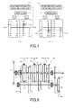
- a general 6-speed manual transmission (hereinafter referred to as a transmission) will be described with reference to Fig. 8 .
- a transmission TM includes an input shaft 10, an output shaft 11, and a counter shaft 12.
- the output shaft 11 is disposed coaxially with this input shaft 10.
- the counter shaft 12 is disposed parallel to the input shaft 10 and output shaft 11.
- An input main gear 13 is disposed on the input shaft 10.
- a 1st speed (1st) main gear M1, a 2nd speed (2nd) main gear M2, a 3rd speed (3rd) main gear M3, a 4th speed (4th) main gear M4, and a reverse main gear MR are journally supported on the output shaft 11, and a 6th speed (6th) main gear M6 is fixedly secured on the output shaft 11.
- an input counter gear 14 engages with the input main gear 13.
- the 1st speed counter gear C1 engages with the 1st speed main gear M1.
- the 2nd speed counter gear C2 engages with the 2nd speed main gear M2.
- the 3rd speed counter gear C3 engages with the 3rd speed main gear M3.
- the 4th speed counter gear C4 engages with the 4th speed main gear M4.
- the reverse counter gear CR engages with the reverse main gear MR via an idle gear IR.
- the 6th speed counter gear C6 engages with the 6th speed main gear M6.
- a sleeve S1 is spline-engaged (meshed) with a hub H1 secured to the output shaft 11.
- the output shaft 11 rotates reversely.
- the sleeve S1 is spline-engaged with a dog D1 of the 1st speed main gear M1
- the output shaft 11 rotates at a speed corresponding to the 1st speed.
- a sleeve S2 is spline-engaged with a hub H2 secured to the output shaft 11.
- a sleeve S4 is spline-engaged with a hub H4 secured to the output shaft 11.
- the output shaft 11 rotates at a speed corresponding to the 4th speed.
- the output shaft 11 rotates at a speed corresponding to the 5th speed (5th) (in the directly-coupled state).
- a sleeve S6 is spline-engaged with a hub H6 secured to the counter shaft 12.
- the output shaft 11 rotates at a speed corresponding to the 6th speed.
- the sleeves S1, S2, S4, and S6 are manually operated by a driver with a driver's shift lever within the driver's cabin via shift forks F1, F2, F4, and F6 and a shift shaft.
- a low speed shift shaft 15a and a high speed shift shaft 15b are disposed parallel to the vehicle width direction and along the longitudinal direction of the vehicle.
- a first shift fork F1 is fixedly secured.
- the first shift fork F1 shifts between the 1st speed and the reverse (Rev).
- a second shift fork F2 is disposed to be movable with respect to the shift shaft 15a.
- the second shift fork F2 shifts between the 2nd speed and the 3rd speed.
- a third shift fork F4 is disposed at a front portion of the high speed shift shaft 15b such that the third shift fork F4 is movable with respect to the shift shaft 15b.
- the third shift fork F4 shifts between the 4th speed and the 5th speed.
- a counter shaft shift 15c is disposed parallel to the shift shaft 15b.
- the shift shaft 15b and the counter shaft shift 15c are coupled together by a link lever 16.
- a fourth shift fork F6 is fixedly secured. The fourth shift fork F6 shifts to the 6th speed.
- a boss 17a is disposed in front of the second shift fork F2.
- a reverse-1st speed shift block B1 is integral with the boss 17a.
- a boss 17b is disposed behind the third shift fork F4.
- a 6th speed shift block B6 is integral with the boss 17b.
- a 2nd speed-3rd speed shift block B2 and a 4th speed-5th speed shift block B4 are arranged.
- the 2nd speed-3rd speed shift block B2 is coupled to the second shift fork F2 by a coupling member 18a.
- the 4th speed-5th speed shift block B4 is coupled to the third shift fork F4 by a coupling member 18b.
- the reverse-1st speed shift block B1, the 2nd speed-3rd speed shift block B2, the 4th speed-5th speed shift block B4, and the 6th speed shift block B6 are arranged from the low speed gear to the high speed gear.
- select operations are sequentially performed from the neutral position of the reverse-1st speed to those of the 2nd speed-3rd speed, the 4th speed-5th speed, and the 6th speed.
- a shift operation is performed from the neutral position of the selected shift block B1, B2, B4, or B6 to a desired gear position (shift position).
- the reverse-1st speed shift block B1 is moved forward by the shift lever. Accordingly, the first shift fork F1 is moved forward via the boss 17a and the shift shaft 15a so as to shift from the neutral position to the 1st speed.
- the reverse-1st speed shift block B1 is moved rearward, the first shift fork F1 is moved rearward so as to shift from the neutral position to the reverse gear position.
- the engagement position of the shift lever is moved to the neutral position of the 2nd speed-3rd speed shift block B2 by the select operation. From this state, the 2nd speed-3rd speed shift block B2 is moved rearward by the shift lever. Accordingly, the second shift fork F2 is moved rearward via the coupling member 18a so as to shift from the neutral position to the 2nd speed. The 2nd speed-3rd speed shift block B2 is moved forward so as to shift from the neutral position to the 3rd speed.
- the shift lever When switching to the 4th speed or the 5th speed is desired, the shift lever is moved to the neutral position of the 4th speed-5th speed shift block B4 by the select operation. Subsequently, the 4th speed-5th speed shift block B4 is moved rearward. Accordingly, the third shift fork F4 is moved rearward via the coupling member 18b so as to shift from the neutral position to the 4th speed. The 4th speed-5th speed shift block B4 is moved forward so as to shift from the neutral position to the 5th speed.
- the shift lever When switching to the 6th speed is desired, the shift lever is moved to the neutral position of the 6th speed shift block B6 by the select operation. Subsequently, the 6th speed shift block B6 is moved rearward. Accordingly, the shift shaft 15b is moved rearward via the boss 17b, and the counter shaft shift 15c is moved forward via the link lever 16. Thus, the fourth shift fork F6 is moved forward so as to shift from the neutral position to the 6th speed.
- reference numeral 19 denotes ball clicks for holding the shafts 15a and 15b at the respective gear positions and neutral positions.
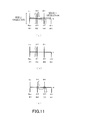
- Fig. 11(a) illustrates the above-described shift patterns of the transmission TM.
- the reverse-1st speed shift block B1 described with reference to Fig. 9 and Fig. 10 is used to perform a shift operation between the reverse and the 1st speed (shift operation to the reverse or to the 1st speed).
- the 2nd speed-3rd speed shift block B2 is used to perform a shift operation between the 2nd speed and the 3rd speed (shift operation to the 2nd speed or to the 3rd speed).
- the 4th speed-5th speed shift block B4 is used to perform a shift operation between the 4th speed and the 5th speed (shift operation to the 4th speed or to the 5th speed).
- the 6th speed shift block B6 is used to perform a shift operation to the 6th speed.
- the shift lever When the shift lever is moved by the select operation, the shift lever is moved along the aligned neutral positions of the reverse-1st speed shift block B1, the 2nd speed-3rd speed shift block B2, the 4th speed-5th speed shift block B4, and the 6th speed shift block B6.
- a select operation is performed on the shift lever so as to move to the neutral position of the 4th speed-5th speed shift block B4, and the gear is engaged from the neutral position to the 4th speed.
- This is an elbow plus elbow (crank) shifting (i.e., shifting with the select operation).
- shift levers it is necessary to provide shift levers to be selectively engaged with the reverse-1st speed shift block B1, the 2nd speed-3rd speed shift block B2, the 4th speed-5th speed shift block B4, and the 6th speed shift block B6.
- the shift levers are driven by actuators such as motors to move the shift blocks B1, B2, B4, and B6.
- the rotation speed of the engine and the rotation speed of the output shaft are detected by rotation sensors in the transmission TM described with reference to Fig. 8 .
- the detection results are introduced to an engine control unit (ECU).
- ECU engine control unit
- a gear shift map speed change map
- a general automatic shifting device which has one actuator for the shift operation and one actuator for the select operation, requires the following operations for the elbow plus elbow shifting. Specifically, disengagement of the gear, a select operation, and a shift operation for engaging the gear are sequentially performed. Additionally, the ECU needs time to determine, by means of its hardware and software, that the respective operations are completed. Accordingly, there is a problem that the elbow plus elbow shifting requires more time for speed change (gear shifting) as compared with the straight shifting.
- actuators A1, A2, A4, and A6 are disposed.
- the actuators A1, A2, A4, and A6 independently operate the shift blocks B1, B2, B4, and B6. These actuators A1, A2, A4, and A6 are sequentially driven so as to eliminate the shift operation.
- the straight shifting is defined as an ordinary shift operation (the shift operation from the 2nd speed to the 3rd speed in the drawing).
- the elbow plus elbow shifting only needs to disengage the gear from the current gear position (the shift operation from the 3rd speed to the neutral position in the drawing), make a determination of the gear disengagement in the position enclosed by a circle illustrated in the drawing, and then perform the shift operation to the desired gear position (the shift operation in the shift block B4 from the neutral position to the 4th speed in the drawing) for gear engagement.
- the actuators A1, A2, A4, and A6 are required corresponding to the number of the shift blocks B1, B2, B4, and B6.
- the driving circuit (mechanism) of these actuators is also required.
- the actuators can be made from cylinders and pistons, but there is a problem that hydraulic piping or pneumatic piping and a hydraulic source or a pneumatic source are required.
- odd speed gear positions are paired, and even gear positions are paired so as to enable straight shifting.
- the straight shifting is enabled between the 1st speed and the 3rd speed
- the straight shifting is enabled between the 5th speed and the reverse
- the straight shifting is enabled between the 2nd speed and the 4th speed
- the straight shifting is enabled to the 6th speed.
- the shift operation is performed with an odd-number-pair actuator Ao
- the shift operation is performed with an even-number-pair actuator Ae.
- the gear position is shifted from 2nd speed to the neutral position by the even-number-pair actuator Ae, and the gear is disengaged. Subsequently, a determination on the gear disengagement is made. Then, the shift operation can be performed from the neutral position to the 3rd speed by the odd-number-pair actuator Ao, and the gear is engaged. From the 3rd speed to the 4th speed, the gear position is shifted from the 3rd speed to the neutral position by the odd-number-pair actuator Ao and the gear is disengaged. Subsequently, a determination on the gear disengagement is made. Then, the shift operation can be performed from the neutral position to 4th speed by the even-number-pair actuator Ae, and the gear is engaged.
- the automatic shifting device of Fig. 13 can operate with the odd-number-pair actuator Ao, the even-number-pair actuator Ae, and the actuator for select operation. This allows reducing the number of actuators. Also, because this allows performing the select operation prior to shifting the gear position, the time for the gear shifting is not adversely influenced.
- the arrangement of the shift blocks B1, B2, B4, and B6 is unchanged, and the shift operations of the shift block B1 in the first row and the shift block B4 in the third row are performed by an actuator Aa whereas the shift operations of the shift block B2 in the second row and the shift block B6 in the fourth row are performed by an actuator Ab.
- This shift pattern can be applied to the existing manual transmission.
- an object of the present invention to provide a transmission device (speed change apparatus) of a vehicle that can solve the above-described problems and perform an automatic gear shift using a manual transmission without modifications.
- the invention of claim 1 provides a transmission device of a vehicle (vehicular transmission device) using a transmission.
- gear positions of a reverse and a 1st speed are arranged opposite to one another
- gear positions of a 2nd speed and a 3rd speed are arranged opposite to one another
- gear positions of a 4th speed and a 5th speed are arranged opposite to one another
- a gear position of a 6th speed is disposed.
- the transmission device includes shift blocks used for shift operations to the gear positions.
- the transmission is configured to perform select operations and then perform shift operations of the shift blocks for automatic gear shifting.
- the transmission device of the vehicle includes first to fourth shift levers, a select actuator, a first shift actuator, a second shift actuator, a gear disengagement determination unit, and a drive unit.
- the shift blocks are arranged in the order from the shift block of the reverse-1st speed, the shift block of the 4th speed-5th speed, the shift block of the 2nd speed-3rd speed, and the shift block of the 6th speed in a direction of the select operation.
- the first to fourth shift levers engage with the shift blocks.
- the select actuator is configured to move, by the select operation, the first to fourth shift levers.
- the first shift actuator is configured to move the first or second shift lever by the shift operation.
- the second shift actuator is configured to move the third or fourth shift lever by the shift operation.
- the gear disengagement determination unit is configured to determine whether a gear disengagement is made at a desired gear position when the gear disengagement and/or gear engagement is performed by the first and second shift actuators.
- the drive unit is configured to drive one of the first and second shift actuators which is used for the gear disengagement.
- the drive unit is configured to drive the other of the first and second shift actuators which is used for the gear engagement when the gear disengagement determination unit determines that the gear disengagement is made.
- the invention of claim 2 is directed to the transmission device of the vehicle according to claim 1.
- the gear positions of the reverse and the 1st speed are arranged opposite to one another
- the gear positions of the 2nd speed and the 3rd speed are arranged opposite to one another
- the gear positions of the 4th speed and the 5th speed are arranged opposite to one another
- shift shafts parallel to one another are disposed at the gear position of the 6th speed.
- a first shift fork is fixedly secured on one of the shift shafts (first shift shaft), and the shift block of the reverse-1st speed is also fixedly secured to the same shift shaft (first shift shaft).
- the first shift fork is configured to move a first sleeve that shifts the gear positions of the reverse and the 1st speed.
- a second shift fork is disposed on the same shift shaft (first shift shaft) such that the second shift fork is movable in an axial direction.
- the second shift fork is configured to move a second sleeve that shifts the gear positions of the 2nd speed and the 3rd speed.
- the shift block of the 2nd speed-3rd speed is coupled to the second shift fork.
- a fourth shift fork is coupled to the other shift shaft (second shift shaft) via a link lever, and the shift block of the 6th speed is fixedly secured to the second shift shaft.
- the fourth shift fork is configured to moves a fourth sleeve that shifts to the gear position of the 6th speed.
- a third shift fork is disposed on the second shift shaft such that the third shift fork is movable in an axial direction.
- the third shift fork is configured to move a third sleeve that shifts the gear positions of the 4th speed and the 5th speed.
- the shift block of the 4th speed-5th speed is coupled to the third shift fork.
- each of the first shift lever and the second shift lever is formed in an L shape.
- the first shift lever is spaced from the second shift lever in an up-down direction, and the first and second shift levers are disposed to be turnable horizontally.
- Each of the first shift lever and the second shift lever has a lever portion in the L-folded part.
- the lever portion of the first shift lever engages with the shift block of the reverse-1st speed
- the lever portion of the second shift lever engages with the shift block of the 4th speed-5th speed.
- Turning of the first shift lever and the second shift lever causes moving, by the shift operation, of the shift block of the reverse-1st speed and the shift block of the 4th speed-5th speed via the lever portions.
- each of the third shift lever and the fourth shift lever is formed in an L shape.
- the third shift lever is spaced from the fourth shift lever in the up-down direction, and the third and fourth shift levers are disposed to be turnable horizontally.
- the third shift lever and the fourth shift lever are disposed opposite the first shift lever and the second shift lever.
- Each of the third shift lever and the fourth shift lever has a lever portion in the L-folded part.
- the lever portion of the third shift lever engages with the shift block of the 2nd speed-3rd speed
- the invention of claim 5 is directed to the transmission device of the vehicle according to claim 1.
- the gear disengagement determination unit has sensors for detecting amounts of shift (movements) of the respective shift blocks or the first and second shift actuators.
- the gear disengagement determination unit determines, based on the amounts of shift detected by the sensors, whether the gear disengagement is made.
- the drive unit receives a determination result of "gear disengaged” or “gear disengagement made” from the gear disengagement determination unit.
- the drive unit drives the first or second shift actuator, without additional operation, to perform the gear disengagement or engagement.
- the drive unit drives (moves) the shift actuator which is used for the gear disengagement to a neutral position upon determination of the gear disengagement, and also drives the other shift actuator, which is used for the gear engagement, to perform the gear engagement.
- the present invention simply changing the arrangement order of the shift blocks provides an excellent effect that allows automatic gear shifting with a simple structure using the existing manual transmission.
- the present invention also has an excellent effect that allows parallel activation of the shift actuators for the gear disengagement and gear engagement during the elbow plus elbow shifting because the gear disengagement is detected prior to moving the gear position to the neutral position, when the gear engagement and disengagement are performed by the shift actuators. This significantly reduces time for gear shifting.
- the transmission TM to be used in the embodiment of the present invention is as described in Fig. 8 . Thus, the description of the transmission TM is omitted.
- This shift control system of the transmission TM in Fig. 1 to Fig. 3 is basically the same as the conventional shift control system described with reference to Fig. 9 and Fig. 10 .
- Same or like reference numerals designate identical or corresponding elements in the following description.
- the arrangement configuration of the shift shafts 15a and 15b and the first to fourth shift forks F1, F2, F4, and F6 are the same. This configuration will be described below.
- the low speed and high speed shift shafts 15a and 15b are disposed parallel to the vehicle width direction and along the longitudinal direction of the vehicle direction.
- the first shift fork F1 is fixedly secured.
- the first shift fork F1 shifts between the 1st speed and the reverse (Rev).
- the second shift fork F2 is disposed to be movable in the axial direction with respect to the shift shaft 15a.
- the second shift fork F2 shifts between the 2nd speed and the 3rd speed.
- the third shift fork F4 is disposed at the front portion of the high speed shift shaft 15b such that the third shift fork F4 is movable in the axial direction with respect to the shift shaft 15b.
- the third shift fork F4 shifts between the 4th speed and the 5th speed.
- the counter shaft shift 15c is disposed parallel to the shift shaft 15b.
- the shift shaft 15b and the counter shaft shift 15c are coupled together by the link lever 16.
- the fourth shift fork F6 is fixedly secured on the counter shaft shift 15c. The fourth shift fork F6 shifts to the 6th speed.
- the shift block B1 of the reverse-1st speed, the shift block B4 of the 4th speed-5th speed, the shift block B2 of the 2nd speed-3rd speed, and the shift block B6 of the 6th speed are arranged in the select operation direction from the low speed shift shaft 15a to the high speed shift shaft 15b in Figs. 9 and 10 .
- this arrangement is compared with the arrangement illustrated in Figs. 9 and 10 , the shift block B2 of the 2nd speed-3rd speed and the shift block B4 of the 4th speed-5th speed are reversed in position.
- the shift block B1 of the reverse-1st speed is fixedly secured on the shift shaft 15a via the boss 17a.
- the shift block B6 of the 6th speed is fixedly secured on the other shift shaft 15b via the boss 17b.
- the shift block B4 of the 4th speed-5th speed is coupled to the third shift fork F4 by a coupling member 21a.
- the shift block B2 of the 2nd speed-3rd speed is coupled to the second shift fork F2 by a coupling member 21b.
- an elongated hole 22 is formed in the shift block B2 of the 2nd speed-3rd speed.
- a guide shaft 23 is fitted in the elongated hole 22.
- the guide shaft 23 is disposed at the boss 17b of the shift block B6 of the 6th speed.
- the elongated hole 22 of the shift block B6 of the 6th speed and the guide shaft 23 guide the movement of the shift block B6 of the 6th speed in the shift operation direction.
- an elongated hole 22 is also formed in the shift block B4 of the 4th speed-5th speed because the shift block B4 having the elongated hole 22 can be fabricated as a common component with the shift block B6 of the 6th speed.
- first to fourth shift levers 24a, 25a, 25b, 24b are respectively engaged in the arrangement order.
- the shift operations are performed with the first to fourth shift levers 24a, 25a, 25b, and 24b.
- the first shift lever 24a and the second shift lever 25a are disposed opposite to the third shift lever 25b and the fourth shift lever 24b, and are formed in an L shape.
- the second shift lever 25a and the first shift lever 24a are disposed to be distant from each other in the up-down direction (height direction) and to be turnable horizontally (in a horizontal plane) about a shaft 28a.
- a lever portion 26a in the L folded part engages with the shift block B1 of the reverse-1st speed.
- a lever portion 27a in the L folded part engages with the shift block B4 of the 4th speed-5th speed.
- the third shift lever 25b and the fourth shift lever 24b are disposed to be distant from each other in the up-down direction and to be turnable in the horizontal plane about to a shaft 28b.
- a lever portion 27b in the L folded part engages with the shift block B2 of the 2nd speed-3rd speed.
- a lever portion 26b in the L folded part engages with the shift block B6 of the 6th speed.
- the first to fourth shift levers 24a, 25a, 25b, and 24b are turned around the shafts 28a and 28b so as to move, by the shift operation, the respective shift blocks B1, B4, B2, and B6 via the associated lever portions 26a, 27a, 27b, and 26b.
- the first shift lever 24a which shifts the shift block B1 of the reverse-1st speed, or the second shift lever 25a, which shifts the shift block B4 of the 4th speed-5th speed, is moved by a first select actuator 30a for the select operation. After the select operation, the first shift lever 24a or the second shift lever 25a is moved by a first shift actuator 31a for the shift operation.
- the third shift lever 25b which shifts the shift block B2 of the 2nd speed-3rd speed, or the fourth shift lever 24b, which shifts the shift block B6 of the 6th speed, is moved by a second select actuator 30b for the select operation. After the select operation, the third shift lever 25b or the fourth shift lever 24b is moved by a second shift actuator 31b for the shift operation.
- the first and second select actuators 30a and 30b include select motors 33a and 33b and rotatable shift cylindrical bodies 34a and 34b.
- the shift cylindrical body 34a or 34b engages with any of the rear ends of the first and second shift levers 24a and 25a or the rear ends of the third and fourth shift levers 25b and 24b (the rear ends opposite the lever portions 26a, 27a, 27b, and 26b) upon rotation of the select motor 33a or 33b.
- Turning gears 35a and 35b are disposed at the select motors 33a and 33b.
- select gears 36a and 36b are disposed at the shift cylindrical bodies 34a and 34b.
- the select gears 36a and 36b engage with the turning gears 35a and 35b.
- a pair of engagement protrusions 37a and 37b are disposed on the opposite sides of the select gears 36a and 36b at the shift cylindrical bodies 34a and 34b.
- the engagement protrusion 37a or 37b engages with any of the rear ends of the first and second shift levers 24a and 25a or the rear ends of the third and fourth shift levers 25b and 24b (the rear ends opposite the lever portions 26a, 27a, 27b, and 26b).
- the first and second shift actuators 31a and 31b include shift motors 40a and 40b and ball screws 41a and 41b ( Fig. 6 ).
- the ball screws 41a and 41b are coupled to the shift motors 40a and 40b, and are threadably mounted on nut portions 38a and 38b of the shift cylindrical bodies 34a and 34b so as to reciprocate the shift cylindrical bodies 34a and 34b in the shift operation direction.
- U-shaped interlock plates 42a and 42b are disposed on the shafts of the ball screws 41a and 41b.
- the interlock plates 42a and 42b house (receive) the distal end portions of the engagement protrusions 37a and 37b of the shift cylindrical bodies 34a and 34b, and the rotations of the interlock plates 42a and 42b are restricted (regulated) by the shift cylindrical bodies 34a and 34b.
- the interlock plates 42a and 42b have interlock grooves 43a and 43b and depression grooves (recesses) 44a and 44b.
- the interlock grooves 43a and 43b guide the shift cylindrical bodies 34a and 34b in the shift operation direction.
- the grooves 44a and 44b receive the rear ends (ends opposite the lever portions 26a, 27a, 27b, 26b) of the first to fourth shift levers 24a, 25a, 25b, and 24b between the engagement protrusions 37a and 37b. Movements of the shift levers 24a, 25a, 25b, and 24b that are not selected by the engagement protrusions 37a and 37b are restricted (regulated) by the grooves 44a and 44b.
- the first and second select actuators 30a and 30b control the rotation positions of the shift cylindrical bodies 34a and 34b via the turning gears 35a and 35b and the select gears 36a and 36b with the forward direction rotation or the reverse direction rotation of the select motors 33a and 33b.
- the first and second select actuators 30a and 30b select one of the two positions of the engagement protrusions 37a and 37b. At one of the two positions (higher position), the engagement protrusions 37a and 37b are engaged with the rear ends of the second shift lever 25a and the third shift lever 25b (the rear ends opposite the lever portions 27a and 27b). At the other position (lower position), the engagement protrusions 37a and 37b are engaged with the rear ends of the first and fourth shift levers 24a and 24b (the rear ends opposite the lever portions 26a and 26b).
- the shift motors 40a and 40b of the first and second shift actuators 31a and 31b are rotated in the forward rotation direction or the reverse rotation direction.
- the shift cylindrical bodies 34a and 34b are moved from the neutral position in the shift operation direction by the ball screws 41a and 41b.
- the first to fourth shift levers 24a, 25a, 25b, and 24b are turned around the shafts 28a and 28b so as to move the shift blocks B1, B4, B2, and B6 in the shift operation direction via the lever portions 26a, 27a, 27b, and 26b.
- the gear is engaged at a desired gear position or the gear is disengaged from a desired gear position to the neutral position.
- the second shift actuator 31b is moved by the straight shifting, without additional operation (movement).
- the first shift actuator 31a is moved by the straight shifting, without additional operation.
- the elbow plus elbow shifting is needed.
- the first shift actuator 31a or the second shift actuator 31b which is used for the gear disengagement moves the shift block B1, B4, B2, B6 to the neutral position
- the second shift actuator 31b or the first shift actuator 31a which is used for the gear engagement moves the shift block B1, B4, B2, B6 toward the gear engagement position. Therefore, when the elbow plus elbow shifting is compared with the straight shifting that only drives one of the first shift and second shift actuators 31a and 31b alone, the elbow plus elbow shifting requires more time than the straight shifting.
- the embodiment of the present invention employs the gear disengagement determination unit 50 to determine whether the gear disengagement is made by the first or second shift actuator 31a, 31b. Immediately after the gear disengagement determination unit 50 determines that the gear disengagement is made, the drive unit 51 drives the first or second shift actuator 31a, 31b for the gear disengagement and simultaneously drives the second or first shift actuator 31b, 31a for the gear engagement.
- the gear disengagement determination unit 50 has sensors 52a and 52b for detecting an amount of shift (movement) caused by the first or second shift actuator 31a, 31b, or an amount of shift (movement) of each of the shift blocks B1, B4, B2 and B6.
- the gear disengagement determination unit 50 determines whether the gear disengagement is made or not, based on the amount(s) of shift detected by the sensors 52a and/or 52b.
- the sleeve S1, S2, S4 or S6 meshes (spline-engages) with the dog DR or D1, the dog D2 or D3, the dog D4 or D5, or the dog D6 when the gear engagement is made.
- the gear disengagement is in effect made (substantive gear disengagement is made) prior to reaching the neutral position. Because the range for this meshing (spline engagement) is decided by the design specifications of the transmission TM to be used, it is possible for the sensors 52a and 52b to detect an amount of shift (movement) to exit the meshing range (gear disengagement determination position). It should be noted that the ECU may determine the meshing ranges of the respective gears (dogs) by means of initial learning, and store the position data (gear disengagement determination position) at which the respective shift blocks exit the meshing ranges (spline engagement ranges).
- an amount of shift to exit the respective meshing range is stored in the gear disengagement determination unit 50.
- the drive unit 51 drives the second or first shift actuator 31b, 31a for the gear engagement while driving the first or second shift actuator 31a, 31b for the gear disengagement.
- the ECU selects the gear position using the engine rotation speed, the engine load, the output shaft rotation speed (vehicle speed), and other parameters based on a speed change map that is stored in the ECU beforehand.
- the shift block B1, B2, B4 or B6 is already moved by the select operation, and the first or second shift actuator 31a, 31b now moves the shift block B1, B2, B4 or B6 by the shift operation.
- the sensor 52a, 52b detects a gear disengagement determination position of each gear position from the shift amount of each shift actuator 31a, 31b, the moved position of each shift block B1, B4, B2, B6 and other information.
- the sensors 52a and 52b send the detected positions to the gear disengagement determination unit 50.
- the gear disengagement determination unit 50 determines whether the gear disengagement is made, based on the detection value of the sensor 52a, 52b when the shift block B1, B4, B2, B6 is moved from the gear engagement state to the neutral position N by the shift operation.
- the drive unit 51 drives the second shift actuator 31b by the straight shifting without additional operation.
- the drive unit 51 drives the first shift actuator 31a by the straight shifting without additional operation.
- the drive unit 51 drives the second shift actuator 31b to move the shift block B2 of the 2nd speed-3rd speed to the neutral position N from the 3rd speed gear-engaged state for the gear disengagement.
- the drive unit 51 also drives the first shift actuator 31a to perform the gear engagement to the 4th speed from the neutral position.
- the sensor 52b detects the gear disengagement while the shift block B2 is being moved to the neutral position N from the 3rd speed gear-engaged state.
- the sensor 52b sends a signal representing the gear disengagement to the drive unit 51 via the gear disengagement determination unit 50. Accordingly, the drive unit 51 simultaneously drives the first shift actuator 31a, in parallel to the second shift actuator 31b, to move the shift block B4 to the 4th speed gear position from the neutral position N by the shift operation.
- the drive unit 51 drives the first shift actuator 31a to move the shift block B4 of the 4th speed-5th speed to the neutral position No from the 4th speed gear-engaged state for the gear disengagement.
- the drive unit 51 simultaneously drives the second shift actuator 31b, in parallel to the first shift actuator 31a, to move the shift block B2 to the third gear position from the neutral position N by the shift operation.
- the drive unit 51 simultaneously drives the first and second shift actuators 31a and 31b when the gear disengagement determination unit 50 determines the gear disengagement. This is similar to the elbow plus elbow shifting between the 3rd speed and the 4th speed.
- the first shift actuator 31a and the second shift actuator 31b are driven in parallel from a position of when the gear disengagement is detected by the sensor 52a, 52b to the neutral position N. Therefore, the gear shift for the elbow plus elbow shifting can be performed in substantially the same time as the straight shift between the 2nd speed and the 3rd speed or between the 4th speed and the 5th speed. Consequently, it is possible to significantly reduce the time spent for the gear shifting.
- the embodiment of the present invention uses the conventional transmission.
- the shift block B2 of the 2nd speed-3rd speed and the shift block B4 of the 4th speed-5th speed are reversed in position, as compared with the conventional shift block arrangement.
- the shift blocks are arranged in the order from the low speed gear to the high speed gear.
- the shift blocks B2 and B4 are coupled to the shift forks F2 and F4 via the coupling members 21a and 21b.
- This simple configuration allows an automatic shift with a simple structure using the existing manual transmission.
- the gear engagement and gear disengagement are performed by the shift actuators 31a and 31b, the gear disengagement is detected before the gear position returns to the neutral position N.
- the elbow and elbow shifting it is possible to drive the gear-engaging and gear-disengaging shift actuators 31a and 31b in parallel. This results in significant reduction in the gear shifting time.
Landscapes
- Engineering & Computer Science (AREA)
- General Engineering & Computer Science (AREA)
- Mechanical Engineering (AREA)
- Gear-Shifting Mechanisms (AREA)
- Control Of Transmission Device (AREA)
Applications Claiming Priority (2)
| Application Number | Priority Date | Filing Date | Title |
|---|---|---|---|
| JP2012117590A JP5962205B2 (ja) | 2012-05-23 | 2012-05-23 | 車両の変速装置 |
| PCT/JP2013/063686 WO2013176036A1 (ja) | 2012-05-23 | 2013-05-16 | 車両の変速装置 |
Publications (3)
| Publication Number | Publication Date |
|---|---|
| EP2853780A1 true EP2853780A1 (de) | 2015-04-01 |
| EP2853780A4 EP2853780A4 (de) | 2017-03-29 |
| EP2853780B1 EP2853780B1 (de) | 2018-05-16 |
Family
ID=49623730
Family Applications (1)
| Application Number | Title | Priority Date | Filing Date |
|---|---|---|---|
| EP13794520.0A Not-in-force EP2853780B1 (de) | 2012-05-23 | 2013-05-16 | Vorrichtung zur änderung der drehzahl eines fahrzeugs |
Country Status (5)
| Country | Link |
|---|---|
| US (1) | US9739373B2 (de) |
| EP (1) | EP2853780B1 (de) |
| JP (1) | JP5962205B2 (de) |
| CN (1) | CN104285082B (de) |
| WO (1) | WO2013176036A1 (de) |
Cited By (2)
| Publication number | Priority date | Publication date | Assignee | Title |
|---|---|---|---|---|
| WO2020164884A1 (de) * | 2019-02-12 | 2020-08-20 | Knorr-Bremse Systeme für Nutzfahrzeuge GmbH | Schaltelement für ein fahrzeuggetriebe |
| EP3828445A1 (de) * | 2019-11-27 | 2021-06-02 | KNORR-BREMSE Systeme für Nutzfahrzeuge GmbH | Aktuatoranordnung für ein getriebe |
Families Citing this family (10)
| Publication number | Priority date | Publication date | Assignee | Title |
|---|---|---|---|---|
| DE102013004953A1 (de) * | 2013-03-22 | 2014-09-25 | Audi Ag | Aktuatoreinrichtung für ein Getriebe eines Kraftfahrzeugs sowie entsprechendes Getriebe eines Kraftfahrzeugs |
| DE102014200257A1 (de) * | 2014-01-09 | 2015-07-09 | Brose Fahrzeugteile GmbH & Co. Kommanditgesellschaft, Würzburg | Aktorbaugruppe für die Gangwahl in einem Fahrzeuggetriebe |
| KR101637693B1 (ko) * | 2014-10-15 | 2016-07-08 | 현대자동차주식회사 | 수동변속기용 변속 장치 |
| KR101637513B1 (ko) * | 2015-03-24 | 2016-07-07 | 한국파워트레인 주식회사 | 듀얼 클러치 변속기의 구동장치 |
| WO2018042456A1 (en) * | 2016-08-31 | 2018-03-08 | Mahindra And Mahindra Limited | Transmission control mechanism in a manual dual clutch power transmission unit of a vehicle |
| US10495216B2 (en) * | 2017-01-26 | 2019-12-03 | Kongsberg Automotive As | Interrocker assembly |
| KR20210006035A (ko) * | 2019-07-08 | 2021-01-18 | 현대자동차주식회사 | 변속기의 변속 액츄에이터 |
| EP3825582B1 (de) * | 2019-11-20 | 2024-04-10 | Stellantis Europe S.p.A. | System zum betrieb eines getriebes für ein kraftfahrzeug |
| CN111503264B (zh) * | 2020-03-24 | 2021-07-27 | 陕西法士特齿轮有限责任公司 | 一种八挡变速器挡位结构 |
| CN113217625B (zh) * | 2021-05-31 | 2022-08-12 | 东风商用车有限公司 | 一种拨叉结构件、机械锁档结构及变速箱 |
Citations (5)
| Publication number | Priority date | Publication date | Assignee | Title |
|---|---|---|---|---|
| US4911031A (en) * | 1987-09-29 | 1990-03-27 | Isuzo Motors Limited | Transmission control apparatus |
| US20010025535A1 (en) * | 2000-01-27 | 2001-10-04 | Mitsutoshi Kamiya | Apparatus for setting selection gate positions for change speed in automatic gear transmission |
| JP2005188626A (ja) * | 2003-12-25 | 2005-07-14 | Isuzu Motors Ltd | 変速操作装置 |
| US20070142153A1 (en) * | 2003-12-05 | 2007-06-21 | Yusuke Kasuya | Automatic shift type manual tranmission |
| US20110252920A1 (en) * | 2010-04-15 | 2011-10-20 | Hyundai Wia Corporation | Gear Shifting Actuator and Method of Shifting Gear Ratios |
Family Cites Families (14)
| Publication number | Priority date | Publication date | Assignee | Title |
|---|---|---|---|---|
| JPS6184451A (ja) * | 1984-10-01 | 1986-04-30 | Aisin Warner Ltd | 変速機の変速制御装置 |
| JP2878881B2 (ja) * | 1991-10-07 | 1999-04-05 | 本田技研工業株式会社 | 常時噛合式変速機 |
| JP4378775B2 (ja) * | 1997-12-09 | 2009-12-09 | いすゞ自動車株式会社 | 歯車変速機 |
| JP4447771B2 (ja) * | 1997-12-23 | 2010-04-07 | ルーク ラメレン ウント クツプルングスバウ ベタイリグングス コマンディートゲゼルシャフト | 伝動装置 |
| JP2002317872A (ja) * | 2001-04-19 | 2002-10-31 | Fuji Heavy Ind Ltd | 自動変速機 |
| JP4247953B2 (ja) * | 2001-11-02 | 2009-04-02 | 日産ディーゼル工業株式会社 | 車両の機械式自動変速装置 |
| JP4101528B2 (ja) * | 2002-02-15 | 2008-06-18 | いすゞ自動車株式会社 | ギヤ段判定装置 |
| US6882925B2 (en) | 2002-02-13 | 2005-04-19 | Isuzu Motors Limited | Gear stage detection device |
| JP2003301896A (ja) * | 2002-04-09 | 2003-10-24 | Siemens Vdo Automotive Kk | 変速機、変速方法 |
| JP2007046659A (ja) * | 2005-08-09 | 2007-02-22 | Hitachi Ltd | 車両の制御装置及び制御方法 |
| JP4235845B2 (ja) * | 2007-06-11 | 2009-03-11 | 三菱自動車工業株式会社 | 変速装置 |
| JP5141561B2 (ja) * | 2009-01-08 | 2013-02-13 | いすゞ自動車株式会社 | 自動変速装置 |
| JP2010230111A (ja) * | 2009-03-27 | 2010-10-14 | Mitsubishi Motors Corp | デュアルクラッチ変速機 |
| US8677852B2 (en) * | 2010-02-23 | 2014-03-25 | GM Global Technology Operations LLC | Multiplexed electromechanical actuator mechanism |
-
2012
- 2012-05-23 JP JP2012117590A patent/JP5962205B2/ja not_active Expired - Fee Related
-
2013
- 2013-05-16 EP EP13794520.0A patent/EP2853780B1/de not_active Not-in-force
- 2013-05-16 WO PCT/JP2013/063686 patent/WO2013176036A1/ja active Application Filing
- 2013-05-16 CN CN201380022611.XA patent/CN104285082B/zh active Active
- 2013-05-16 US US14/394,560 patent/US9739373B2/en active Active
Patent Citations (5)
| Publication number | Priority date | Publication date | Assignee | Title |
|---|---|---|---|---|
| US4911031A (en) * | 1987-09-29 | 1990-03-27 | Isuzo Motors Limited | Transmission control apparatus |
| US20010025535A1 (en) * | 2000-01-27 | 2001-10-04 | Mitsutoshi Kamiya | Apparatus for setting selection gate positions for change speed in automatic gear transmission |
| US20070142153A1 (en) * | 2003-12-05 | 2007-06-21 | Yusuke Kasuya | Automatic shift type manual tranmission |
| JP2005188626A (ja) * | 2003-12-25 | 2005-07-14 | Isuzu Motors Ltd | 変速操作装置 |
| US20110252920A1 (en) * | 2010-04-15 | 2011-10-20 | Hyundai Wia Corporation | Gear Shifting Actuator and Method of Shifting Gear Ratios |
Non-Patent Citations (1)
| Title |
|---|
| See also references of WO2013176036A1 * |
Cited By (4)
| Publication number | Priority date | Publication date | Assignee | Title |
|---|---|---|---|---|
| WO2020164884A1 (de) * | 2019-02-12 | 2020-08-20 | Knorr-Bremse Systeme für Nutzfahrzeuge GmbH | Schaltelement für ein fahrzeuggetriebe |
| EP3828445A1 (de) * | 2019-11-27 | 2021-06-02 | KNORR-BREMSE Systeme für Nutzfahrzeuge GmbH | Aktuatoranordnung für ein getriebe |
| WO2021104894A1 (en) * | 2019-11-27 | 2021-06-03 | Knorr-Bremse Systeme für Nutzfahrzeuge GmbH | Actuator arrangement for a gearbox |
| CN114746676A (zh) * | 2019-11-27 | 2022-07-12 | 克诺尔商用车制动系统有限公司 | 用于变速箱的致动器装置 |
Also Published As
| Publication number | Publication date |
|---|---|
| CN104285082A (zh) | 2015-01-14 |
| EP2853780A4 (de) | 2017-03-29 |
| US20150075308A1 (en) | 2015-03-19 |
| JP5962205B2 (ja) | 2016-08-03 |
| WO2013176036A1 (ja) | 2013-11-28 |
| JP2013245698A (ja) | 2013-12-09 |
| US9739373B2 (en) | 2017-08-22 |
| EP2853780B1 (de) | 2018-05-16 |
| CN104285082B (zh) | 2016-07-06 |
Similar Documents
| Publication | Publication Date | Title |
|---|---|---|
| EP2853780B1 (de) | Vorrichtung zur änderung der drehzahl eines fahrzeugs | |
| EP2851584B1 (de) | Fahrzeuggetriebevorrichtung | |
| US7197954B2 (en) | Double-clutch transmission architecture for a motor vehicle | |
| CN101255919B (zh) | 用于汽车的双离合器变速器及其伺服辅助换档的控制装置 | |
| CN102207191B (zh) | 一种用于机械式自动变速系统的丝杠式换挡执行机构 | |
| US20160160962A1 (en) | Power transmitting apparatus for vehicle | |
| US20090320635A1 (en) | Transmission | |
| CN103256351B (zh) | 多离合器变速装置 | |
| CN101283204B (zh) | 用于自动配置自动机械变速器和电子控制器的方法 | |
| CN102434664A (zh) | 汽车变速器选/换档操纵装置 | |
| KR101512226B1 (ko) | 하나의 축을 이용한 농기계의 변속레버 어셈블리 | |
| JP5772145B2 (ja) | 車両の自動変速装置 | |
| CN105805296A (zh) | 离合器自动接合或分离的机械换挡 | |
| JP6011020B2 (ja) | 車両の変速装置 | |
| JP4448824B2 (ja) | 自動シフト式手動変速機 | |
| JP2012207685A (ja) | 車両の自動変速装置 | |
| US20150152961A1 (en) | Method and apparatus of preventing unintended gear selection in a compound transmission | |
| JP2014047881A (ja) | パーキングロック装置 | |
| CN108603593A (zh) | 实施车辆的换挡变速器的选挡的换挡执行器、车辆的换挡变速器系统、车辆的驱动系和用于安装车辆的换挡变速器的换挡执行器的方法 | |
| KR101610510B1 (ko) | 하이브리드 차량 변속기용 쉬프트 액츄에이터 | |
| JP2020159364A (ja) | 変速操作装置 | |
| JP4957708B2 (ja) | 自動変速機の変速操作装置 | |
| KR20120131454A (ko) | 변속기의 자동화 변속장치 |
Legal Events
| Date | Code | Title | Description |
|---|---|---|---|
| PUAI | Public reference made under article 153(3) epc to a published international application that has entered the european phase |
Free format text: ORIGINAL CODE: 0009012 |
|
| 17P | Request for examination filed |
Effective date: 20141218 |
|
| AK | Designated contracting states |
Kind code of ref document: A1 Designated state(s): AL AT BE BG CH CY CZ DE DK EE ES FI FR GB GR HR HU IE IS IT LI LT LU LV MC MK MT NL NO PL PT RO RS SE SI SK SM TR |
|
| AX | Request for extension of the european patent |
Extension state: BA ME |
|
| DAX | Request for extension of the european patent (deleted) | ||
| RA4 | Supplementary search report drawn up and despatched (corrected) |
Effective date: 20170227 |
|
| RIC1 | Information provided on ipc code assigned before grant |
Ipc: F16H 63/20 20060101ALI20170221BHEP Ipc: F16H 61/02 20060101AFI20170221BHEP Ipc: F16H 61/32 20060101ALI20170221BHEP Ipc: F16H 63/30 20060101ALI20170221BHEP |
|
| GRAP | Despatch of communication of intention to grant a patent |
Free format text: ORIGINAL CODE: EPIDOSNIGR1 |
|
| STAA | Information on the status of an ep patent application or granted ep patent |
Free format text: STATUS: GRANT OF PATENT IS INTENDED |
|
| INTG | Intention to grant announced |
Effective date: 20171121 |
|
| GRAS | Grant fee paid |
Free format text: ORIGINAL CODE: EPIDOSNIGR3 |
|
| GRAA | (expected) grant |
Free format text: ORIGINAL CODE: 0009210 |
|
| STAA | Information on the status of an ep patent application or granted ep patent |
Free format text: STATUS: THE PATENT HAS BEEN GRANTED |
|
| AK | Designated contracting states |
Kind code of ref document: B1 Designated state(s): AL AT BE BG CH CY CZ DE DK EE ES FI FR GB GR HR HU IE IS IT LI LT LU LV MC MK MT NL NO PL PT RO RS SE SI SK SM TR |
|
| REG | Reference to a national code |
Ref country code: GB Ref legal event code: FG4D |
|
| REG | Reference to a national code |
Ref country code: CH Ref legal event code: EP |
|
| REG | Reference to a national code |
Ref country code: DE Ref legal event code: R096 Ref document number: 602013037586 Country of ref document: DE |
|
| REG | Reference to a national code |
Ref country code: IE Ref legal event code: FG4D |
|
| REG | Reference to a national code |
Ref country code: AT Ref legal event code: REF Ref document number: 999887 Country of ref document: AT Kind code of ref document: T Effective date: 20180615 |
|
| REG | Reference to a national code |
Ref country code: FR Ref legal event code: PLFP Year of fee payment: 6 |
|
| PGFP | Annual fee paid to national office [announced via postgrant information from national office to epo] |
Ref country code: DE Payment date: 20180622 Year of fee payment: 6 |
|
| PGFP | Annual fee paid to national office [announced via postgrant information from national office to epo] |
Ref country code: FR Payment date: 20180628 Year of fee payment: 6 |
|
| REG | Reference to a national code |
Ref country code: NL Ref legal event code: MP Effective date: 20180516 |
|
| REG | Reference to a national code |
Ref country code: LT Ref legal event code: MG4D |
|
| PG25 | Lapsed in a contracting state [announced via postgrant information from national office to epo] |
Ref country code: LT Free format text: LAPSE BECAUSE OF FAILURE TO SUBMIT A TRANSLATION OF THE DESCRIPTION OR TO PAY THE FEE WITHIN THE PRESCRIBED TIME-LIMIT Effective date: 20180516 Ref country code: SE Free format text: LAPSE BECAUSE OF FAILURE TO SUBMIT A TRANSLATION OF THE DESCRIPTION OR TO PAY THE FEE WITHIN THE PRESCRIBED TIME-LIMIT Effective date: 20180516 Ref country code: NO Free format text: LAPSE BECAUSE OF FAILURE TO SUBMIT A TRANSLATION OF THE DESCRIPTION OR TO PAY THE FEE WITHIN THE PRESCRIBED TIME-LIMIT Effective date: 20180816 Ref country code: FI Free format text: LAPSE BECAUSE OF FAILURE TO SUBMIT A TRANSLATION OF THE DESCRIPTION OR TO PAY THE FEE WITHIN THE PRESCRIBED TIME-LIMIT Effective date: 20180516 Ref country code: BG Free format text: LAPSE BECAUSE OF FAILURE TO SUBMIT A TRANSLATION OF THE DESCRIPTION OR TO PAY THE FEE WITHIN THE PRESCRIBED TIME-LIMIT Effective date: 20180816 Ref country code: ES Free format text: LAPSE BECAUSE OF FAILURE TO SUBMIT A TRANSLATION OF THE DESCRIPTION OR TO PAY THE FEE WITHIN THE PRESCRIBED TIME-LIMIT Effective date: 20180516 |
|
| PGFP | Annual fee paid to national office [announced via postgrant information from national office to epo] |
Ref country code: GB Payment date: 20180628 Year of fee payment: 6 |
|
| PG25 | Lapsed in a contracting state [announced via postgrant information from national office to epo] |
Ref country code: LV Free format text: LAPSE BECAUSE OF FAILURE TO SUBMIT A TRANSLATION OF THE DESCRIPTION OR TO PAY THE FEE WITHIN THE PRESCRIBED TIME-LIMIT Effective date: 20180516 Ref country code: GR Free format text: LAPSE BECAUSE OF FAILURE TO SUBMIT A TRANSLATION OF THE DESCRIPTION OR TO PAY THE FEE WITHIN THE PRESCRIBED TIME-LIMIT Effective date: 20180817 Ref country code: HR Free format text: LAPSE BECAUSE OF FAILURE TO SUBMIT A TRANSLATION OF THE DESCRIPTION OR TO PAY THE FEE WITHIN THE PRESCRIBED TIME-LIMIT Effective date: 20180516 Ref country code: NL Free format text: LAPSE BECAUSE OF FAILURE TO SUBMIT A TRANSLATION OF THE DESCRIPTION OR TO PAY THE FEE WITHIN THE PRESCRIBED TIME-LIMIT Effective date: 20180516 Ref country code: RS Free format text: LAPSE BECAUSE OF FAILURE TO SUBMIT A TRANSLATION OF THE DESCRIPTION OR TO PAY THE FEE WITHIN THE PRESCRIBED TIME-LIMIT Effective date: 20180516 |
|
| REG | Reference to a national code |
Ref country code: CH Ref legal event code: PL |
|
| REG | Reference to a national code |
Ref country code: AT Ref legal event code: MK05 Ref document number: 999887 Country of ref document: AT Kind code of ref document: T Effective date: 20180516 |
|
| REG | Reference to a national code |
Ref country code: BE Ref legal event code: MM Effective date: 20180531 |
|
| PG25 | Lapsed in a contracting state [announced via postgrant information from national office to epo] |
Ref country code: AT Free format text: LAPSE BECAUSE OF FAILURE TO SUBMIT A TRANSLATION OF THE DESCRIPTION OR TO PAY THE FEE WITHIN THE PRESCRIBED TIME-LIMIT Effective date: 20180516 Ref country code: DK Free format text: LAPSE BECAUSE OF FAILURE TO SUBMIT A TRANSLATION OF THE DESCRIPTION OR TO PAY THE FEE WITHIN THE PRESCRIBED TIME-LIMIT Effective date: 20180516 Ref country code: EE Free format text: LAPSE BECAUSE OF FAILURE TO SUBMIT A TRANSLATION OF THE DESCRIPTION OR TO PAY THE FEE WITHIN THE PRESCRIBED TIME-LIMIT Effective date: 20180516 Ref country code: CZ Free format text: LAPSE BECAUSE OF FAILURE TO SUBMIT A TRANSLATION OF THE DESCRIPTION OR TO PAY THE FEE WITHIN THE PRESCRIBED TIME-LIMIT Effective date: 20180516 Ref country code: RO Free format text: LAPSE BECAUSE OF FAILURE TO SUBMIT A TRANSLATION OF THE DESCRIPTION OR TO PAY THE FEE WITHIN THE PRESCRIBED TIME-LIMIT Effective date: 20180516 Ref country code: SK Free format text: LAPSE BECAUSE OF FAILURE TO SUBMIT A TRANSLATION OF THE DESCRIPTION OR TO PAY THE FEE WITHIN THE PRESCRIBED TIME-LIMIT Effective date: 20180516 Ref country code: PL Free format text: LAPSE BECAUSE OF FAILURE TO SUBMIT A TRANSLATION OF THE DESCRIPTION OR TO PAY THE FEE WITHIN THE PRESCRIBED TIME-LIMIT Effective date: 20180516 |
|
| REG | Reference to a national code |
Ref country code: DE Ref legal event code: R097 Ref document number: 602013037586 Country of ref document: DE |
|
| REG | Reference to a national code |
Ref country code: IE Ref legal event code: MM4A |
|
| PG25 | Lapsed in a contracting state [announced via postgrant information from national office to epo] |
Ref country code: CH Free format text: LAPSE BECAUSE OF NON-PAYMENT OF DUE FEES Effective date: 20180531 Ref country code: IT Free format text: LAPSE BECAUSE OF FAILURE TO SUBMIT A TRANSLATION OF THE DESCRIPTION OR TO PAY THE FEE WITHIN THE PRESCRIBED TIME-LIMIT Effective date: 20180516 Ref country code: SM Free format text: LAPSE BECAUSE OF FAILURE TO SUBMIT A TRANSLATION OF THE DESCRIPTION OR TO PAY THE FEE WITHIN THE PRESCRIBED TIME-LIMIT Effective date: 20180516 Ref country code: LI Free format text: LAPSE BECAUSE OF NON-PAYMENT OF DUE FEES Effective date: 20180531 |
|
| PLBE | No opposition filed within time limit |
Free format text: ORIGINAL CODE: 0009261 |
|
| STAA | Information on the status of an ep patent application or granted ep patent |
Free format text: STATUS: NO OPPOSITION FILED WITHIN TIME LIMIT |
|
| PG25 | Lapsed in a contracting state [announced via postgrant information from national office to epo] |
Ref country code: MC Free format text: LAPSE BECAUSE OF FAILURE TO SUBMIT A TRANSLATION OF THE DESCRIPTION OR TO PAY THE FEE WITHIN THE PRESCRIBED TIME-LIMIT Effective date: 20180516 Ref country code: LU Free format text: LAPSE BECAUSE OF NON-PAYMENT OF DUE FEES Effective date: 20180516 |
|
| 26N | No opposition filed |
Effective date: 20190219 |
|
| PG25 | Lapsed in a contracting state [announced via postgrant information from national office to epo] |
Ref country code: IE Free format text: LAPSE BECAUSE OF NON-PAYMENT OF DUE FEES Effective date: 20180516 |
|
| PG25 | Lapsed in a contracting state [announced via postgrant information from national office to epo] |
Ref country code: SI Free format text: LAPSE BECAUSE OF FAILURE TO SUBMIT A TRANSLATION OF THE DESCRIPTION OR TO PAY THE FEE WITHIN THE PRESCRIBED TIME-LIMIT Effective date: 20180516 Ref country code: BE Free format text: LAPSE BECAUSE OF NON-PAYMENT OF DUE FEES Effective date: 20180531 |
|
| PG25 | Lapsed in a contracting state [announced via postgrant information from national office to epo] |
Ref country code: AL Free format text: LAPSE BECAUSE OF FAILURE TO SUBMIT A TRANSLATION OF THE DESCRIPTION OR TO PAY THE FEE WITHIN THE PRESCRIBED TIME-LIMIT Effective date: 20180516 |
|
| REG | Reference to a national code |
Ref country code: DE Ref legal event code: R119 Ref document number: 602013037586 Country of ref document: DE |
|
| GBPC | Gb: european patent ceased through non-payment of renewal fee |
Effective date: 20190516 |
|
| PG25 | Lapsed in a contracting state [announced via postgrant information from national office to epo] |
Ref country code: MT Free format text: LAPSE BECAUSE OF NON-PAYMENT OF DUE FEES Effective date: 20180516 |
|
| PG25 | Lapsed in a contracting state [announced via postgrant information from national office to epo] |
Ref country code: TR Free format text: LAPSE BECAUSE OF FAILURE TO SUBMIT A TRANSLATION OF THE DESCRIPTION OR TO PAY THE FEE WITHIN THE PRESCRIBED TIME-LIMIT Effective date: 20180516 |
|
| PG25 | Lapsed in a contracting state [announced via postgrant information from national office to epo] |
Ref country code: GB Free format text: LAPSE BECAUSE OF NON-PAYMENT OF DUE FEES Effective date: 20190516 Ref country code: DE Free format text: LAPSE BECAUSE OF NON-PAYMENT OF DUE FEES Effective date: 20191203 |
|
| PG25 | Lapsed in a contracting state [announced via postgrant information from national office to epo] |
Ref country code: PT Free format text: LAPSE BECAUSE OF FAILURE TO SUBMIT A TRANSLATION OF THE DESCRIPTION OR TO PAY THE FEE WITHIN THE PRESCRIBED TIME-LIMIT Effective date: 20180516 Ref country code: HU Free format text: LAPSE BECAUSE OF FAILURE TO SUBMIT A TRANSLATION OF THE DESCRIPTION OR TO PAY THE FEE WITHIN THE PRESCRIBED TIME-LIMIT; INVALID AB INITIO Effective date: 20130516 |
|
| PG25 | Lapsed in a contracting state [announced via postgrant information from national office to epo] |
Ref country code: CY Free format text: LAPSE BECAUSE OF FAILURE TO SUBMIT A TRANSLATION OF THE DESCRIPTION OR TO PAY THE FEE WITHIN THE PRESCRIBED TIME-LIMIT Effective date: 20180516 Ref country code: FR Free format text: LAPSE BECAUSE OF NON-PAYMENT OF DUE FEES Effective date: 20190531 Ref country code: MK Free format text: LAPSE BECAUSE OF NON-PAYMENT OF DUE FEES Effective date: 20180516 |
|
| PG25 | Lapsed in a contracting state [announced via postgrant information from national office to epo] |
Ref country code: IS Free format text: LAPSE BECAUSE OF FAILURE TO SUBMIT A TRANSLATION OF THE DESCRIPTION OR TO PAY THE FEE WITHIN THE PRESCRIBED TIME-LIMIT Effective date: 20180916 |