EP2850939A1 - Wickelvorrichtung und eine für diese verwendende Rundballenpresse - Google Patents
Wickelvorrichtung und eine für diese verwendende Rundballenpresse Download PDFInfo
- Publication number
- EP2850939A1 EP2850939A1 EP14177016.4A EP14177016A EP2850939A1 EP 2850939 A1 EP2850939 A1 EP 2850939A1 EP 14177016 A EP14177016 A EP 14177016A EP 2850939 A1 EP2850939 A1 EP 2850939A1
- Authority
- EP
- European Patent Office
- Prior art keywords
- axis
- winding device
- bale
- arm
- winding
- Prior art date
- Legal status (The legal status is an assumption and is not a legal conclusion. Google has not performed a legal analysis and makes no representation as to the accuracy of the status listed.)
- Granted
Links
Images


Classifications
-
- A—HUMAN NECESSITIES
- A01—AGRICULTURE; FORESTRY; ANIMAL HUSBANDRY; HUNTING; TRAPPING; FISHING
- A01F—PROCESSING OF HARVESTED PRODUCE; HAY OR STRAW PRESSES; DEVICES FOR STORING AGRICULTURAL OR HORTICULTURAL PRODUCE
- A01F15/00—Baling presses for straw, hay or the like
- A01F15/07—Rotobalers, i.e. machines for forming cylindrical bales by winding and pressing
- A01F15/071—Wrapping devices
-
- A—HUMAN NECESSITIES
- A01—AGRICULTURE; FORESTRY; ANIMAL HUSBANDRY; HUNTING; TRAPPING; FISHING
- A01F—PROCESSING OF HARVESTED PRODUCE; HAY OR STRAW PRESSES; DEVICES FOR STORING AGRICULTURAL OR HORTICULTURAL PRODUCE
- A01F15/00—Baling presses for straw, hay or the like
- A01F15/07—Rotobalers, i.e. machines for forming cylindrical bales by winding and pressing
- A01F15/071—Wrapping devices
- A01F2015/073—Features related to the horizontal rotating arm of a wrapping device of the satellite type
-
- A—HUMAN NECESSITIES
- A01—AGRICULTURE; FORESTRY; ANIMAL HUSBANDRY; HUNTING; TRAPPING; FISHING
- A01F—PROCESSING OF HARVESTED PRODUCE; HAY OR STRAW PRESSES; DEVICES FOR STORING AGRICULTURAL OR HORTICULTURAL PRODUCE
- A01F15/00—Baling presses for straw, hay or the like
- A01F15/07—Rotobalers, i.e. machines for forming cylindrical bales by winding and pressing
- A01F15/071—Wrapping devices
- A01F2015/0735—Combined machines that include a press bale and a wrapping device in a further step, e.g. turning table, not in the same closed pressing chamber
Definitions
- the present invention relates to a winding device for wrapping bales, in particular of agricultural crop, and a baler using such a winding device.
- Object of the present invention is to provide a winding device with a reduced footprint, or to provide a baler that builds shorter without sacrificing performance over a conventional baler with integrated winding device.
- the object is achieved, on the one hand, by providing, in a winding device for wrapping bales, in particular, harvested agricultural material having a wrapping table for supporting a bale to be wrapped and rotating the bale about a horizontal axis and at least one wrapping material dispenser movable on a horizontal path around the bale includes, the length of the arm is coupled coupled to its rotation about the axis variable.
- This makes it possible, in particular, to guide the winding material dispenser a small distance from the bale and thus to reduce the space required for wrapping the bale.
- a baler equipped with the winding device according to the invention can thus be made more compact.
- the distance of a track traced by the wrapping material dispenser from the center of the substantially rectangular bale in plan view is greater in at least two outer track sections adjacent to corners of the bale than in an inner track section connecting the outer track sections.
- the inner track section will generally have a greater radius of curvature than the outer track sections adjacent thereto. Ideally, the inner track section is straight and parallel to an adjacent flank of the bale.
- the control of the change in length of the arm is particularly simple when the vertical axis about which the arm rotates passes through the center of the bale.
- the arm can expediently have a close-to-the-axis and at least one off-axis element which engage in one another in a radially movable manner.
- one of the elements may act as a rail along which the other is movable.
- the arm may comprise a hydraulic or, preferably, a pneumatic actuator. Valves for pressurizing the actuator can be controlled by the rotation of the arm.
- a non-rotatably arranged link can be provided, which is scanned by the arm in the course of its rotation about the axis.
- the arm may comprise an eccentric driven by its rotation about the axis.
- the eccentric should expediently make four turns per revolution of the arm about the vertical axis.
- the hydraulic or pneumatic actuator of the embodiment mentioned above can expediently perform four cycles of movement per revolution of the arm.
- the off-axis element of the arm can additionally be pivotably connected to the element close to the axis and be articulated to a drive body which rotates about the vertical axis at a different rotational speed than the axis-near element.
- the speed of the rotor may in particular be five times or, in the opposite direction of rotation, three times the speed of rotation of the arm.
- the object is further achieved by a round baler with a pressing chamber and a winding device according to one of the preceding claims.
- the inner web portion extends on a side facing the pressing chamber edge of the bale, it allows to shorten the distance between the changing table and press chamber, thereby making the entire round baler compact.
- Fig. 1 shows in a side view a baling press according to the present invention.
- a front part of the baler is occupied by a pressing chamber 1.
- the pressing chamber 1 forms fed crop into a cylindrical bale with a horizontal axis and wraps around it with binding material as soon as it has reached a desired size.
- a bale is produced which has substantially the shape of a cylinder with a horizontal axis.
- the bale is often slightly barrel-shaped.
- An output flap 2 at the rear of the pressing chamber 1 is shown in the open position to output the finished bale 3 on a changing table 4 arranged behind the pressing chamber 1 winding device 5.
- the changing table 4 comprises a plurality of rotatable rollers 6 and bands wound around the roller 6 and supporting the bales 3. By a roller 6 is driven in rotation, the bale 3 can be rotated about its horizontal axis of symmetry 7 in rotation.
- An arched door 8 is arranged between the pressing chamber 1 and changing table 4 on a support frame 9 of the baler and extending in an angle to the side over the changing table 4.
- a rear tip of the archway 8 are two arms 10, driven by a motor 12 to a rotatably mounted centrally through the bale 3 extending vertical axis 11.
- the arms 10 each carry a wrapping material dispenser 13, such as a roller with plastic film to be wrapped around the bale 3.
- Fig. 2 shows a plan view of the winding device 5.
- the per se cylindrical bale 3 appears in the plan view substantially rectangular, in particular square.
- the arms 10 are moved around the bale 3, while it is simultaneously rotated by the changing table 4 about its horizontal axis of symmetry 7.
- the Fig. 2 shows the two arms 10 each in a plurality of positions that they pass through on their movement around the bale 3.
- the web 14 of the wrapping material dispenser 13 is not circular, but substantially rectangular, in particular square, wherein the vertical axis 11 forms the center of the square and track sections 15a, b, c, d, in which the distance the rollers 13 of the axis 11 is large and the direction of movement of the winding material dispenser 13 changes sharply over a short distance, each adjacent to the corners of the bale 3 and by each other along the flanks of the bale 3 extending slightly curved or even rectilinear track sections 16a, b . c, d, are connected.
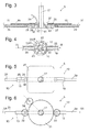
- Fig. 3 shows a central part of the winding device 5 according to a first embodiment of the invention in a section along the vertical axis 11.
- a partially shown, extending in the direction of the axis 11 shaft 17 is connected in its unillustrated part of the motor 12.
- a hub 18 is rotatably mounted, in each of which a near-axis element 19 of the two arms 10 is anchored.
- the near-axis elements 19 are each tubular, and an off-axis element 20 is radially slidably received in each near-axis element 19.
- the near-axis element 19 each forms a cylinder and the off-axis element 20 a piston of an actuating cylinder and define a working chamber 25th
- a distributor ring 21 is non-rotatably connected to the archway 8 and engages in an annularly extending around the shaft 17 groove of the hub 18 a.
- FIG. 4 can be seen in the distribution ring 21 eight to an outer edge of the distribution ring 21 open towards edge recesses 22, 23 are formed.
- the edge recesses 22 are connected to a compressed air supply line 24, the edge recesses 23 connected to the environment. In the circumferential direction of the edge, the recesses 22 and 23 alternate with each other.
- the recesses 22 connected to the compressed air supply line 24 communicate with a working chamber 25 formed by the elements 19, 20, respectively, as the arms 10 move towards the center of one of the web sections 16a-d to the subsequent web section 15a-d and on the way from the web section 15a -d to the center of the next track section 16a-d the working chambers 25 are connected via the recesses 23 to the environment, and the off-axis elements 20 are pulled by a tension spring 26 to the axis 11, the winding material dispensers 13 on the in Fig. 2 shown, substantially rectangular track 14 out.
- the actuating cylinder could, according to a modification, be double-acting in order to drive both inward and outward movement of the off-axis elements 20; the tension spring 26 could then be omitted.
- Fig. 5 shows a plan view of the winding device 5 according to a second embodiment.
- the shaft 17 here intersects a guide 27 (not shown), which is arranged so as to be non-rotatable.
- the elements 19 close to the axis are again formed as tubes in which the elements 20 remote from the axis are displaceable.
- Pins 26 secured to the off-axis elements each extend through a slot 29 of the near-axis element 19 of the arm 10 and each carry a roller 30 which extends from an unillustrated element at both off-axis elements 20 attacking tension spring against the periphery of the gate 27 is acted upon.
- a third embodiment is in Fig. 6 in a plan view and in Fig. 7 shown in a section along the vertical axis 11.
- a gear 31 of large diameter is arranged concentrically to the shaft 17 and rotatably anchored to the archway 8.
- the near-axis elements 19 of the arms 10 each carry a small gear 32 whose number of teeth is one-fifth of that of the large gear 31 and which meshes with the large gear 31.
- the gears 32 are each rotatably connected to eccentrics 33, which carry a rotatably engaging in the off-axis elements 20 pin 34.
- attached to the tips of the near-axis elements 19 pin 35 pass through a slot 36 of the off-axis elements 20th
- the pins 34 are each in their next closest to the axis 11 position, so that the distance of the winding material dispenser 13, not shown in the figure, mounted at the ends of the arms 10 from the axis 11 is minimal.
- the shaft 17 here carries a sun gear 37 of a planetary gear
- the ring gear 38 is fixed to the archway 8
- the planetary gears 39 are rotatable about the achsnahen elements 19 of the arms 10 anchored shafts 40 and a rotation of the arms 10 about the axis 11 with a fifth the speed of the shaft 17 drive.
- the lower end of the shaft 17 is formed as a crankshaft with two crank pins 41 which form about the axis 11 rotating and acting on the off-axis elements 20 of the two arms 10 driving body.
- anchored pin 35 again pass through slots 36 of the off-axis elements 20 to allow both a radial movement of the off-axis elements 20 and a pendulum motion about the axes defined by the pins 35.
- Fig. 9 shown by a schematic plan view.
- the direction of rotation of the arm 10 is clockwise; in a first configuration, the near-axis member 19 of the arm 10 is in a nine o'clock position with respect to the axle 11, the shaft journal 41 is in the three o'clock position, the pin 35 passes through the slot 36 near its off-axis end, and the radius of the arm 10 is minimal.
- the axle near member 19 are rotated 45 ° and the crankpin 41 by 225 ° clockwise, and the pin 35 is located in the center of the slot 36.
- the crank pin 41 is positioned in a line between the axle 11 and the pins 35, the pin 35 is located at an inner end of the slot 36, and the arm 10 has reached its maximum length.
- the end of the arm 10 has meanwhile covered a nearly straight path, corresponding to one half of the track section 16a.
- the web portion 15a is reached;
- the direction of movement changes abruptly, so that in the course of one revolution of the arm 10, the wrapping material dispenser 13 carried by it describes a nearly square path.
Landscapes
- Life Sciences & Earth Sciences (AREA)
- Environmental Sciences (AREA)
- Storage Of Harvested Produce (AREA)
Abstract
Description
- Die vorliegende Erfindung betrifft eine Wickelvorrichtung zum Umwickeln von Ballen, insbesondere von landwirtschaftlichem Erntegut, sowie eine Ballenpresse, die eine solche Wickelvorrichtung verwendet.
- Aus
EP 2 050 330 A1 ist eine Ballenpresse bekannt, die in einem vorderen Bereich eine Presskammer zum Formen eines Ballens sowie, hinter der Presskammer, eine Wickelvorrichtung zum Umwickeln eines in der Presskammer fertig gestellten und über eine Klappe an der Rückseite der Presskammer ausgegebenen Ballens aufweist. Das Umwickeln mit einer luftundurchlässigen Folie ermöglicht ein Silieren des Ballens unter freiem Himmel und ist daher für die Viehfuttererzeugung attraktiv. Im Vergleich zu einer Ballenpresse ohne Wickelvorrichtung wird durch die Integration der Wickelvorrichtung ein erheblicher Produktivitätszuwachs erzielt, da die Ballen nicht mehr vom Feld aufgenommen werden müssen, um sie nachträglich zu umwickeln. Nachteilig ist jedoch der erhebliche Längenzuwachs, der mit der Integration der Wickelvorrichtung einhergeht. Er macht die Ballenpresse schwierig zu manövrieren und erhöht erheblich ihren Platzbedarf in einem Unterstand bei Nichtgebrauch. - Aufgabe der vorliegenden Erfindung ist, eine Wickelvorrichtung mit vermindertem Platzbedarf zu schaffen, bzw. eine Ballenpresse zu schaffen, die ohne Einbuße an Leistungsfähigkeit gegenüber einer herkömmlichen Ballenpresse mit integrierter Wickelvorrichtung kürzer baut.
- Die Aufgabe wird zum einen gelöst, indem bei einer Wickelvorrichtung zum Umwickeln von Ballen insbesondere von landwirtschaftlichem Erntegut, die einen Wickeltisch zum Unterstützen eines zu umwickelnden Ballens und zum Rotieren des Ballens um eine horizontale Achse und wenigstens einen auf einer horizontalen Bahn um den Ballen bewegbaren Wickelmaterialspender umfasst, die Länge des Arms gekoppelt an seine Drehung um die Achse variabel ist. Dadurch ist es insbesondere möglich, den Wickelmaterialspender in geringem Abstand vom Ballen zu führen und so den zum Umwickeln des Ballens benötigten Freiraum zu verkleinern. Eine mit der erfindungsgemäßen Wickelvorrichtung ausgestattete Ballenpresse lässt sich somit kompakter bauen.
- Vorzugsweise ist der Abstand einer von dem Wickelmaterialspender verfolgten Bahn vom Mittelpunkt des in Draufsicht im wesentlichen rechteckigen Ballens in wenigstens zwei zu Ecken des Ballens benachbarten äußeren Bahnabschnitten größer als in einem die äußeren Bahnabschnitte verbindenden inneren Bahnabschnitt. Indem auf diese Weise an wenigstens einer Seite des Ballens der Wickelmaterialspender anstelle der herkömmlichen Kreisbahn eine näher am Ballen verlaufende Bahn verfolgt, kann an dieser Seite der Abstand zur Presskammer vermindert werden, ohne dass dies die Beweglichkeit einer Ausgabeklappe der Presskammer einschränkt.
- Der innere Bahnabschnitt wird im Allgemeinen einen größeren Krümmungsradius aufweisen als die daran angrenzenden äußeren Bahnabschnitte. Im Idealfall verläuft der innere Bahnabschnitt geradlinig und parallel zu einer benachbarten Flanke des Ballens.
- Die Steuerung der Längenveränderung des Arms ist besonders einfach, wenn die vertikale Achse, um die der Arm rotiert, durch den Mittelpunkt des Ballens verläuft.
- Der Arm kann zweckmäßigerweise ein achsnahes und wenigstens ein achsfernes Element aufweisen, die radial beweglich ineinander greifen. Insbesondere kann eines der Elemente als eine Schiene fungieren, entlang derer das andere beweglich ist.
- Zum Antreiben einer die Länge des Arms variierenden Bewegung kann der Arm ein hydraulisches oder, bevorzugtermaßen, pneumatisches Stellglied aufweisen. Ventile zum Beaufschlagen des Stellglieds mit Druckmedium können durch die Drehung des Arms gesteuert sein.
- Einer alternativen Ausgestaltung zufolge kann eine drehfest angeordnete Kulisse vorgesehen sein, die von dem Arm im Laufe seiner Drehung um die Achse abgetastet wird.
- Noch einer alternativen Ausgestaltung zufolge kann der Arm einen von seiner Drehung um die Achse angetriebenen Exzenter umfassen. Um den Arm an jeder Ecke des Balles zu verlängern und ihn zwischen den Ecken zu verkürzen, sollte der Exzenter zweckmäßigerweise pro Umdrehung des Arms um die vertikale Achse vier Umdrehungen ausführen. Entsprechend kann auch das hydraulische oder pneumatische Stellglied der weiter oben erwähnten Ausgestaltung zweckmäßigerweise vier Bewegungszyklen pro Umdrehung des Arms ausführen.
- Einer weiteren alternativen Ausgestaltung zufolge kann das achsferne Element des Arms mit dem achsnahen Element zusätzlich schwenkbar verbunden und an einen Antriebskörper angelenkt sein, der um die vertikale Achse mit einer anderen Drehzahl rotiert als das achsnahe Element. Um vier Zyklen der Abstandsänderung zwischen Wickelmaterialspender und Mittelpunkt des Ballens bei jeder Umdrehung des Arms zu realisieren, kann die Geschwindigkeit des Rotors insbesondere das Fünffache oder, bei gegensinniger Drehrichtung, das Dreifache der Drehgeschwindigkeit des Arms betragen.
- Wenn sich zwei Wickelmaterialspender bezüglich der vertikalen Achse isometrisch gegenüber liegen, kann der Wickelvorgang beschleunigt und eine Unwucht beim Umwickeln des Ballens vermieden werden.
- Die Aufgabe wird ferner gelöst durch eine Rundballenpresse mit einer Presskammer und einer Wickelvorrichtung nach einer der vorhergehenden Ansprüche. Indem der innere Bahnabschnitt an einer der Presskammer zugewandten Flanke des Ballens verläuft, erlaubt er es, den Abstand zwischen Wickeltisch und Presskammer zu verkürzen und dadurch die gesamte Rundballenpresse kompakter zu bauen.
- Weitere Merkmale und Vorteile der Erfindung ergeben sich aus der nachfolgenden Beschreibung von Ausführungsbeispielen unter Bezugnahme auf die beigefügten Figuren. Es zeigen:
- Fig. 1
- eine Seitenansicht einer erfindungsgemäßen Ballenpresse;
- Fig. 2
- eine Draufsicht auf eine Wickelvorrichtung der Ballenpresse;
- Fig. 3
- einen schematischen axialen Teilschnitt durch die Wickelvorrichtung entlang der Ebene III-III aus
Fig. 4 gemäß einer ersten Ausgestaltung; - Fig. 4
- einen schematischen Teilschnitt durch die Wickelvorrichtung senkrecht zu ihrer Drehachse, entlang der Ebene IV-IV aus
Fig. 3 ; - Fig. 5
- eine schematische Draufsicht auf die Wickelvorrichtung gemäß einer zweiten Ausgestaltung;
- Fig. 6
- eine schematische Draufsicht gemäß einer dritten Ausgestaltung;
- Fig. 7
- einen Schnitt entlang der Drehachse gemäß der dritten Ausgestaltung;
- Fig. 8
- einen Schnitt entlang der Drehachse gemäß einer vierten Ausgestaltung;
- Fig. 9
- eine Draufsicht auf die Wickelvorrichtung der vierten Ausgestaltung in verschiedenen Phasen ihrer Bewegung.
-
Fig. 1 zeigt in einer Seitenansicht eine Ballenpresse gemäß der vorliegenden Erfindung. Ein vorderer Teil der Ballenpresse ist von einer Presskammer 1 eingenommen. Ihre Arbeitsweise und ihre Aufbau sind an sich bekannt und brauchen daher hier nicht im Detail erläutert zu werden. Die Presskammer 1 formt zugeführtes Erntegut zu einem zylindrischen Ballen mit horizontaler Achse und umschlingt diesen mit Bindematerial, sobald er eine gewünschte Größe erreicht hat. So wird ein Ballen erzeugt, der im Wesentlichen die Form eines Zylinders mit horizontaler Achse hat. In der Praxis ist der Ballen häufig leicht tonnenförmig. Eine Ausgabeklappe 2 am Heck der Presskammer 1 ist in offener Stellung gezeigt, um den fertigen Ballen 3 auf einen Wickeltisch 4 einer hinter der Presskammer 1 angeordneten Wickelvorrichtung 5 auszugeben. - Der Wickeltisch 4 umfasst mehrere drehbare Walzen 6 und um die Walze 6 herumgeschlungene, den Ballen 3 unterstützende Bänder. Indem eine Walze 6 drehangetrieben wird, kann der Ballen 3 um seine horizontale Symmetrieachse 7 in Drehung versetzt werden.
- Ein Torbogen 8 ist zwischen Presskammer 1 und Wickeltisch 4 an einem Trägerrahmen 9 der Ballenpresse angeordnet und erstreckt sich in der Seitenansicht winkelförmig bis über den Wickeltisch 4. An einer hinteren Spitze des Torbogens 8 sind zwei Arme 10, angetrieben von einem Motor 12, um eine mittig durch den Ballen 3 verlaufende vertikale Achse 11 drehbar montiert. Die Arme 10 tragen jeweils einen Wickelmaterialspender 13 wie etwa eine Rolle mit um den Ballen 3 herum zu wickelnder Kunststofffolie.
-
Fig. 2 zeigt eine Draufsicht auf die Wickelvorrichtung 5. Der an sich zylindrische Ballen 3 erscheint in der Draufsicht im Wesentlichen rechteckig, insbesondere quadratisch. Um den Ballen 3 zu umwickeln, werden die Arme 10 um den Ballen 3 herumbewegt, während dieser gleichzeitig vom Wickeltisch 4 um seine horizontale Symmetrieachse 7 rotiert wird. DieFig. 2 zeigt die beiden Arme 10 jeweils in einer Mehrzahl von Stellungen, die sie auf ihrer Bewegung um den Ballen 3 durchlaufen. Wie hier durch eine gestrichelte Linie angedeutet, ist die Bahn 14 der Wickelmaterialspender 13 nicht kreisförmig, sondern im Wesentlichen rechteckig, insbesondere quadratisch, wobei die vertikale Achse 11 den Mittelpunkt des Quadrats bildet und Bahnabschnitte 15a, b, c, d, in denen der Abstand der Rollen 13 von der Achse 11 groß ist und die Bewegungsrichtung der Wickelmaterialspender 13 sich auf kurzer Strecke stark ändert, jeweils den Ecken des Ballens 3 benachbart sind und miteinander durch sich entlang der Flanken des Ballens 3 erstreckende schwach gekrümmte oder gar geradlinige Bahnabschnitte 16a, b, c, d, verbunden sind. Da sich einer dieser Bahnabschnitte, 16a, entlang der der Presskammer 1 zugewandten Flanke des Ballens 3 erstreckt, kann der Abstand zwischen Wickeltisch 4 und Presskammer 1 gering gemacht werden, ohne dass die Arme 10 bzw. die Wickelmaterialspender 13 bei ihrer Bewegung an die Ausgabeklappe 2 anstoßen, auch wenn diese sich nach Ausgabe des Ballens 3 wieder in der die Presskammer 1 verschließenden Stellung befindet. -
Fig. 3 zeigt einen zentralen Teil der Wickelvorrichtung 5 gemäß einer ersten Ausgestaltung der Erfindung in einem Schnitt entlang der vertikalen Achse 11. Eine nur zum Teil dargestellte, sich in Richtung der Achse 11 erstreckende Welle 17 ist in ihrem nicht dargestellten Teil mit dem Motor 12 verbunden. An der Welle 17 ist eine Nabe 18 drehfest angebracht, in der jeweils ein achsnahes Element 19 der beiden Arme 10 verankert ist. Die achsnahen Elemente 19 sind jeweils rohrförmig ausgebildet, und ein achsfernes Element 20 ist radial verschiebbar in jedem achsnahen Element 19 aufgenommen. Das achsnahe Element 19 bildet jeweils einen Zylinder und das achsferne Element 20 einen Kolben eines Stellzylinders und begrenzen eine Arbeitskammer 25. - Ein Verteilerring 21 ist drehfest mit dem Torbogen 8 verbunden und greift in eine sich ringförmig um die Welle 17 erstreckende Nut der Nabe 18 ein. Wie in
Fig. 4 zu erkennen, sind in dem Verteilerring 21 acht zu einem äußeren Rand des Verteilerrings 21 hin offene Randaussparungen 22, 23 gebildet. Die Randaussparungen 22 sind mit einer Druckluftversorgungsleitung 24, die Randaussparungen 23 mit der Umgebung verbunden. In Umfangsrichtung des Randes wechseln die Aussparungen 22 und 23 miteinander ab. Indem die mit Druckluftversorgungsleitung 24 verbundenen Aussparung 22 jeweils dann mit einer von den Elementen 19, 20 gebildeten Arbeitskammer 25 kommunizieren, wenn sich die Arme 10 zum Mittelpunkt eines der Bahnabschnitte 16a-d zum nachfolgenden Bahnabschnitt 15a-d bewegen und auf dem Weg von Bahnabschnitt 15a-d zum Mittelpunkt des nächsten Bahnabschnitts 16a-d die Arbeitskammern 25 über die Aussparungen 23 mit der Umgebung verbunden sind, und die achsfernen Elemente 20 von einer Zugfeder 26 zur Achse 11 gezogen werden, werden die Wickelmaterialspender 13 auf der inFig. 2 gezeigten, im Wesentlichen rechteckigen Bahn 14 geführt. - Der Stellzylinder könnte einer Abwandlung zufolge doppelt wirkend ausgebildet sein, um sowohl Einals auch Auswärtsbewegung der achsfernen Elemente 20 anzutreiben; die Zugfeder 26 könnte dann entfallen.
-
Fig. 5 zeigt eine Draufsicht auf die Wickelvorrichtung 5 gemäß einer zweiten Ausgestaltung. Die Welle 17 kreuzt hier eine drehfest am (nicht dargestellten) Torbogen 8 angeordnete Kulisse 27. Die achsnahen Elemente 19 sind wiederum als Rohre ausgebildet, in denen die achsfernen Elemente 20 verschiebbar sind. An den achsfernen Elementen befestigte Zapfen 28 erstrecken sich jeweils durch einen Schlitz 29 des achsnahen Elements 19 des Arms 10 und tragen jeweils eine Rolle 30, die von einer nicht dargestellten, an beiden achsfernen Elementen 20 angreifenden Zugfeder gegen den Umfang der Kulisse 27 beaufschlagt ist. - Eine dritte Ausgestaltung ist in
Fig. 6 in einer Draufsicht und inFig. 7 in einem Schnitt entlang der vertikalen Achse 11 dargestellt. Anstelle der Kulisse 27 ist hier ein Zahnrad 31 von großem Durchmesser konzentrisch zur Welle 17 angeordnet und drehfest am Torbogen 8 verankert. Die achsnahen Elemente 19 der Arme 10 tragen jeweils ein kleines Zahnrad 32, dessen Zähnezahl ein Fünftel derjenigen des großen Zahnrades 31 beträgt und das mit dem großen Zahnrad 31 kämmt. Wie inFig. 7 zu erkennen, sind die Zahnräder 32 jeweils mit Exzentern 33 drehfest verbunden, die einen in die achsfernen Elemente 20 drehbar eingreifenden Zapfen 34 tragen. Weitere, an den Spitzen der achsnahen Elemente 19 angebrachte Zapfen 35 durchsetzen jeweils einen Schlitz 36 der achsfernen Elemente 20. - In der in den
Fig. 6 und7 gezeigten Konfiguration befinden sich die Zapfen 34 jeweils in ihrer zur Achse 11 nächst benachbarten Stellung, sodass die Entfernung der in der Fig. nicht gezeigten, an den Enden der Arme 10 montierten Wickelmaterialspender 13 von der Achse 11 minimal ist. - Wenn die Arme 10 aus der in
Fig. 6 gezeigten Stellung um 45° im Uhrzeigersinn weiter rotiert sind und einer der Arme entlang der strichpunktierten Linie derFig. 6 ausgerichtet ist, dann ist das Zahnrad 32 dieses Arms 10, bedingt durch das Übersetzungsverhältnis der Zahnräder 31, 32, um 5 x 45° = 225° rotiert, und der Zapfen 34 befindet sich in einer Stellung maximaler Entfernung von der Achse 11, so dass der Arm 10 in dieser Stellung seine maximale Länge erreicht und die Wickelmaterialspender 13 sich auf einer insgesamt rechteckähnlichen Bahn um den Ballen 3 herumbewegen. - Eine ähnliche Wirkung ist mit der in
Fig. 8 im Schnitt entlang der Achse 11 gezeigten Ausgestaltung erreichbar. Die Welle 17 trägt hier ein Sonnenrad 37 eines Planetengetriebes, dessen Hohlrad 38 am Torbogen 8 fest ist und dessen Planetenräder 39 um an den achsnahen Elementen 19 der Arme 10 verankerte Wellen 40 drehbar sind und eine Drehung der Arme 10 um die Achse 11 mit einem Fünftel der Drehzahl der Welle 17 antreiben. - Das untere Ende der Welle 17 ist als Kurbelwelle mit zwei Hubzapfen 41 ausgebildet, welche um die Achse 11 rotierende und an den achsfernen Elementen 20 der beiden Arme 10 angreifende Antriebskörper bilden. An den Enden der achsnahen Elemente 19 verankerte Zapfen 35 durchgreifen wiederum Schlitze 36 der achsfernen Elemente 20, um sowohl eine radiale Bewegung der achsfernen Elemente 20 als auch eine Pendelbewegung um die von den Zapfen 35 definierten Achsen zuzulassen.
- Der aus diesem Aufbau resultierende Bewegungsablauf eines Arms 10 ist in
Fig. 9 anhand einer schematischen Draufsicht gezeigt. Die Drehrichtung des Arms 10 ist im Uhrzeigersinn; in einer ersten Konfiguration befindet sich das achsnahe Element 19 des Arms 10 in einer Neun-Uhr-Stellung in Bezug auf die Achse 11, der Wellenzapfen 41 befindet sich in Drei-Uhr-Stellung, der Zapfen 35 durchgreift den Schlitz 36 in der Nähe von dessen achsfernem Ende, und der Radius des Armes 10 ist minimal. - In einer zweiten Konfiguration sind das achsnahe Element 19 um 45° und der Hubzapfen 41 um 225° im Uhrzeigersinn gedreht, und der Zapfen 35 befindet sich in der Mitte des Schlitzes 36. Nach einer weiteren Drehung des achsnahen Elements 19 um 45° ist der Hubzapfen 41 in einer Linie zwischen der Achse 11 und den Zapfen 35 positioniert, der Zapfen 35 befindet sich an einem inneren Ende des Schlitzes 36, und der Arm 10 hat seine maximale Länge erreicht.
- Das Ende des Armes 10 hat währenddessen einen nahezu geradlinigen Weg, entsprechend einer Hälfte des Bahnabschnitts 16a, zurückgelegt. In der dritten gezeigten Konfiguration ist der Bahnabschnitt 15a erreicht; hier ändert sich die Richtung der Bewegung abrupt, so dass im Laufe einer Umdrehung des Armes 10 der von ihm getragene Wickelmaterialspender 13 eine nahezu quadratische Bahn beschreibt.
-
- 1
- Presskammer
- 2
- Ausgabeklappe
- 3
- Ballen
- 4
- Wickeltisch
- 5
- Wickelvorrichtung
- 6
- Walze
- 7
- Symmetrieachse
- 8
- Torbogen
- 9
- Trägerrahmen
- 10
- Arm
- 11
- Achse
- 12
- Motor
- 13
- Wickelmaterialspender
- 14
- Bahn
- 15a-d
- Bahnabschnitt
- 16a-d
- Bahnabschnitt
- 17
- Welle
- 18
- Nabe
- 19
- achsnahes Elemente
- 20
- achsfernes Element
- 21
- Verteilerring
- 22
- Randaussparung
- 23
- Randaussparung
- 24
- Druckluftversorgungsleitung
- 25
- Arbeitskammer
- 26
- Zugfeder
- 27
- Kulisse
- 28
- Zapfen
- 29
- Schlitz
- 30
- Rolle
- 31
- Zahnrad
- 32
- Zahnrad
- 33
- Exzenter
- 34
- Zapfen
- 35
- Zapfen
- 36
- Schlitz
- 37
- Sonnenrad
- 38
- Hohlrad
- 39
- Planetenrad
- 40
- Welle
- 41
- Wellenzapfen
- 42
- Hubzapfen
Claims (11)
- Wickelvorrichtung zum Umwickeln von Ballen (3) insbesondere von landwirtschaftlichem Erntegut, mit einem Wickeltisch (4) zum Unterstützen eines zu umwickelnden Ballens (3) und zum Rotieren des Ballens (3) um eine horizontale Achse (7) und mit wenigstens einem von einem um eine vertikale Achse (11) rotierenden Arm (10) getragenen Wickelmaterialspender (13), dadurch gekennzeichnet, dass die Länge des Arms (10) gekoppelt an seine Drehung um die Achse (11) variabel ist.
- Wickelvorrichtung nach Anspruch 1, dadurch gekennzeichnet, dass der Abstand einer von dem Wickelmaterialspender (13) verfolgten Bahn (14) von der Achse (11) in wenigstens zwei zu Ecken des in Draufsicht im wesentlichen rechteckigen Ballens (3) benachbarten äußeren Bahnabschnitten (15a-d) größer ist als in einem die äußeren Bahnabschnitte (15a-d) verbindenden inneren Bahnabschnitt (16a-d).
- Wickelvorrichtung nach Anspruch 2, dadurch gekennzeichnet, dass der innere Bahnabschnitt (16a-d) einen größeren Krümmungsradius aufweist als die äußeren Bahnabschnitte (15a-d).
- Wickelvorrichtung nach einem der vorhergehenden Ansprüche, dadurch gekennzeichnet, dass der Arm (10) ein achsnahes (19) und wenigstens ein achsfernes Element (20) aufweist, die radial beweglich ineinandergreifen.
- Wickelvorrichtung nach einem der vorhergehenden Ansprüche, dadurch gekennzeichnet, dass der Arm (10) ein hydraulisches oder pneumatisches Stellglied zum Antreiben einer die Länge des Arms (10) variierenden Bewegung aufweist.
- Wickelvorrichtung nach einem der Ansprüche 1 bis 4, gekennzeichnet durch eine drehfest angeordnete Kulisse (16), die von dem Arm (10) im Laufe seiner Drehung um die Achse (11) abgetastet wird.
- Wickelvorrichtung nach einem der Ansprüche 1 bis 4, dadurch gekennzeichnet, dass der Arm (10) einen von der Drehung des Arms (10) um die Achse (11) angetriebenen Exzenter (33) umfasst.
- Wickelvorrichtung nach Anspruch 7, dadurch gekennzeichnet, dass der Exzenter (33) pro Umdrehung des Arms (10) um die vertikale Achse (11) vier Umdrehungen ausführt.
- Wickelvorrichtung nach Anspruch 4, dadurch gekennzeichnet, dass das achsferne Element (20) mit dem achsnahen Element (19) schwenkbar verbunden ist und an einen Antriebskörper (41) angelenkt ist, der um die vertikale Achse (11) mit einer anderen Drehzahl rotiert als das achsnahe Element (19).
- Wickelvorrichtung nach einem der vorhergehenden Ansprüche, dadurch gekennzeichnet, dass zwei Wickelmaterialspender (13) sich bezüglich der vertikalen Achse (11) symmetrisch gegenüberliegen.
- Rundballenpresse mit einer Presskammer (1), einer Wickelvorrichtung (5) nach einem der vorhergehenden Ansprüche und einer Ausgabeklappe (2), die zwischen einer die Presskammer (1) verschließenden Stellung und einer Offenstellung, die den Übergang eines Ballens (3) von der Presskammer (1) zur Wickelvorrichtung (5) ermöglicht, bewegbar ist, wobei der innere Bahnabschnitt (16a) an einer der Presskammer (1) zugewandten Flanke des Ballens (3) verläuft.
Applications Claiming Priority (1)
| Application Number | Priority Date | Filing Date | Title |
|---|---|---|---|
| DE201310015642 DE102013015642A1 (de) | 2013-09-23 | 2013-09-23 | Wickelvorrichtung und diese verwendende Rundballenpresse |
Publications (2)
| Publication Number | Publication Date |
|---|---|
| EP2850939A1 true EP2850939A1 (de) | 2015-03-25 |
| EP2850939B1 EP2850939B1 (de) | 2018-11-28 |
Family
ID=51210297
Family Applications (1)
| Application Number | Title | Priority Date | Filing Date |
|---|---|---|---|
| EP14177016.4A Active EP2850939B1 (de) | 2013-09-23 | 2014-07-15 | Wickelvorrichtung und eine diese verwendende Rundballenpresse |
Country Status (2)
| Country | Link |
|---|---|
| EP (1) | EP2850939B1 (de) |
| DE (1) | DE102013015642A1 (de) |
Cited By (1)
| Publication number | Priority date | Publication date | Assignee | Title |
|---|---|---|---|---|
| CN115568342A (zh) * | 2022-09-20 | 2023-01-06 | 呼伦贝尔市海征机械制造有限责任公司 | 一种两用式捆草机 |
Citations (2)
| Publication number | Priority date | Publication date | Assignee | Title |
|---|---|---|---|---|
| DE3311279A1 (de) * | 1983-03-28 | 1984-10-11 | Karl 7968 Saulgau Moosbrucker | Verfahren und vorrichtung zum umhuellen zylindrischer koerper, wie rollballen aus landwirtschaftlichem erntegut |
| EP2050330A1 (de) | 2007-10-19 | 2009-04-22 | Usines CLAAS France S.A.S. | Ballenwickler zur Wicklung runder Ballen |
Family Cites Families (1)
| Publication number | Priority date | Publication date | Assignee | Title |
|---|---|---|---|---|
| FI111455B (fi) * | 2000-09-04 | 2003-07-31 | Wrapmatic Oy | Menetelmä ja laitteisto kappaleen muovittamiseksi |
-
2013
- 2013-09-23 DE DE201310015642 patent/DE102013015642A1/de not_active Withdrawn
-
2014
- 2014-07-15 EP EP14177016.4A patent/EP2850939B1/de active Active
Patent Citations (2)
| Publication number | Priority date | Publication date | Assignee | Title |
|---|---|---|---|---|
| DE3311279A1 (de) * | 1983-03-28 | 1984-10-11 | Karl 7968 Saulgau Moosbrucker | Verfahren und vorrichtung zum umhuellen zylindrischer koerper, wie rollballen aus landwirtschaftlichem erntegut |
| EP2050330A1 (de) | 2007-10-19 | 2009-04-22 | Usines CLAAS France S.A.S. | Ballenwickler zur Wicklung runder Ballen |
Cited By (1)
| Publication number | Priority date | Publication date | Assignee | Title |
|---|---|---|---|---|
| CN115568342A (zh) * | 2022-09-20 | 2023-01-06 | 呼伦贝尔市海征机械制造有限责任公司 | 一种两用式捆草机 |
Also Published As
| Publication number | Publication date |
|---|---|
| DE102013015642A1 (de) | 2015-03-26 |
| EP2850939B1 (de) | 2018-11-28 |
Similar Documents
| Publication | Publication Date | Title |
|---|---|---|
| DE2634638A1 (de) | Rundballenpresse zum bilden von grossballen | |
| DE1816768A1 (de) | Vorrichtung zum Ausbreiten von Stoffen | |
| WO2017097372A1 (de) | Kotbandantrieb | |
| DE2530320C3 (de) | Bindevorrichtung für Wickelballenpressen | |
| EP2850939B1 (de) | Wickelvorrichtung und eine diese verwendende Rundballenpresse | |
| EP1595438A1 (de) | Maschine zum Aufnehmen und Pressen von landwirtschaftlichem Entegut | |
| EP1386532B1 (de) | Vorrichtung zum Umhüllen von Körpern | |
| DE102018106457B4 (de) | Lüfterrad mit einer zentralen Antriebseinheit | |
| WO2003031303A2 (de) | Falzapparat mit umfangsverstellbarem zylinder | |
| EP3459341A1 (de) | Landwirtschaftliche rundballenpresse | |
| DE3028140C2 (de) | Ladewagen für landwirtschaftliche Massengüter | |
| DE2226368A1 (de) | Fahrbare Ballenpresse | |
| DE1918746A1 (de) | Transfereinrichtung | |
| EP1842606B1 (de) | Vorrichtung zum schleifenförmigen Biegen eines fortlaufenden Drahtes | |
| EP0396978A1 (de) | Kreisbogenförmiges Zahnsegment und Zahnradgetriebe mit einem solchen Zahnsegment | |
| DE2419489A1 (de) | Heurollen-formmaschine | |
| DE19853869A1 (de) | Vorrichtung zur Strangführung und damit ausgerüstete Rundflechtmaschine | |
| AT300437B (de) | Vorrichtung zum Herstellen von Wickeln aus losem Erntegut, insbesondere Halmgut, Futterpflanzen od.dgl. | |
| DE3011183C2 (de) | Rundballenformmaschine | |
| WO2019197019A1 (de) | Mähdrescher | |
| EP3459343B1 (de) | Riemenspannsystem für eine rundballenpresse sowie landwirtschaftliche rundballenpresse | |
| DE102010054112A1 (de) | Richtwerk zum rotierenden Richten von Draht | |
| DE2611521C3 (de) | Einrichtung zur stufenlosen Lageeinstellung eines drehbaren Endverteilers einer Förderleitung, insbesondere eines selbstfahrenden Erntehäckslers | |
| DE2263080C3 (de) | Vorrichtung zum Umsetzen einer Drehbewegung in eine hin- und hergehende Bewegung | |
| DE202005018707U1 (de) | Markise, insbesondere Gelenkarmmarkise |
Legal Events
| Date | Code | Title | Description |
|---|---|---|---|
| PUAI | Public reference made under article 153(3) epc to a published international application that has entered the european phase |
Free format text: ORIGINAL CODE: 0009012 |
|
| 17P | Request for examination filed |
Effective date: 20140715 |
|
| AK | Designated contracting states |
Kind code of ref document: A1 Designated state(s): AL AT BE BG CH CY CZ DE DK EE ES FI FR GB GR HR HU IE IS IT LI LT LU LV MC MK MT NL NO PL PT RO RS SE SI SK SM TR |
|
| AX | Request for extension of the european patent |
Extension state: BA ME |
|
| R17P | Request for examination filed (corrected) |
Effective date: 20150925 |
|
| RBV | Designated contracting states (corrected) |
Designated state(s): AL AT BE BG CH CY CZ DE DK EE ES FI FR GB GR HR HU IE IS IT LI LT LU LV MC MK MT NL NO PL PT RO RS SE SI SK SM TR |
|
| 17Q | First examination report despatched |
Effective date: 20161012 |
|
| STAA | Information on the status of an ep patent application or granted ep patent |
Free format text: STATUS: EXAMINATION IS IN PROGRESS |
|
| GRAP | Despatch of communication of intention to grant a patent |
Free format text: ORIGINAL CODE: EPIDOSNIGR1 |
|
| STAA | Information on the status of an ep patent application or granted ep patent |
Free format text: STATUS: GRANT OF PATENT IS INTENDED |
|
| INTG | Intention to grant announced |
Effective date: 20180830 |
|
| GRAS | Grant fee paid |
Free format text: ORIGINAL CODE: EPIDOSNIGR3 |
|
| GRAA | (expected) grant |
Free format text: ORIGINAL CODE: 0009210 |
|
| STAA | Information on the status of an ep patent application or granted ep patent |
Free format text: STATUS: THE PATENT HAS BEEN GRANTED |
|
| AK | Designated contracting states |
Kind code of ref document: B1 Designated state(s): AL AT BE BG CH CY CZ DE DK EE ES FI FR GB GR HR HU IE IS IT LI LT LU LV MC MK MT NL NO PL PT RO RS SE SI SK SM TR |
|
| REG | Reference to a national code |
Ref country code: CH Ref legal event code: EP |
|
| REG | Reference to a national code |
Ref country code: AT Ref legal event code: REF Ref document number: 1069128 Country of ref document: AT Kind code of ref document: T Effective date: 20181215 |
|
| REG | Reference to a national code |
Ref country code: DE Ref legal event code: R096 Ref document number: 502014010189 Country of ref document: DE |
|
| REG | Reference to a national code |
Ref country code: IE Ref legal event code: FG4D Free format text: LANGUAGE OF EP DOCUMENT: GERMAN |
|
| REG | Reference to a national code |
Ref country code: NL Ref legal event code: MP Effective date: 20181128 |
|
| REG | Reference to a national code |
Ref country code: LT Ref legal event code: MG4D |
|
| PG25 | Lapsed in a contracting state [announced via postgrant information from national office to epo] |
Ref country code: FI Free format text: LAPSE BECAUSE OF FAILURE TO SUBMIT A TRANSLATION OF THE DESCRIPTION OR TO PAY THE FEE WITHIN THE PRESCRIBED TIME-LIMIT Effective date: 20181128 Ref country code: LT Free format text: LAPSE BECAUSE OF FAILURE TO SUBMIT A TRANSLATION OF THE DESCRIPTION OR TO PAY THE FEE WITHIN THE PRESCRIBED TIME-LIMIT Effective date: 20181128 Ref country code: HR Free format text: LAPSE BECAUSE OF FAILURE TO SUBMIT A TRANSLATION OF THE DESCRIPTION OR TO PAY THE FEE WITHIN THE PRESCRIBED TIME-LIMIT Effective date: 20181128 Ref country code: IS Free format text: LAPSE BECAUSE OF FAILURE TO SUBMIT A TRANSLATION OF THE DESCRIPTION OR TO PAY THE FEE WITHIN THE PRESCRIBED TIME-LIMIT Effective date: 20190328 Ref country code: LV Free format text: LAPSE BECAUSE OF FAILURE TO SUBMIT A TRANSLATION OF THE DESCRIPTION OR TO PAY THE FEE WITHIN THE PRESCRIBED TIME-LIMIT Effective date: 20181128 Ref country code: NO Free format text: LAPSE BECAUSE OF FAILURE TO SUBMIT A TRANSLATION OF THE DESCRIPTION OR TO PAY THE FEE WITHIN THE PRESCRIBED TIME-LIMIT Effective date: 20190228 Ref country code: ES Free format text: LAPSE BECAUSE OF FAILURE TO SUBMIT A TRANSLATION OF THE DESCRIPTION OR TO PAY THE FEE WITHIN THE PRESCRIBED TIME-LIMIT Effective date: 20181128 Ref country code: BG Free format text: LAPSE BECAUSE OF FAILURE TO SUBMIT A TRANSLATION OF THE DESCRIPTION OR TO PAY THE FEE WITHIN THE PRESCRIBED TIME-LIMIT Effective date: 20190228 |
|
| PG25 | Lapsed in a contracting state [announced via postgrant information from national office to epo] |
Ref country code: AL Free format text: LAPSE BECAUSE OF FAILURE TO SUBMIT A TRANSLATION OF THE DESCRIPTION OR TO PAY THE FEE WITHIN THE PRESCRIBED TIME-LIMIT Effective date: 20181128 Ref country code: SE Free format text: LAPSE BECAUSE OF FAILURE TO SUBMIT A TRANSLATION OF THE DESCRIPTION OR TO PAY THE FEE WITHIN THE PRESCRIBED TIME-LIMIT Effective date: 20181128 Ref country code: PT Free format text: LAPSE BECAUSE OF FAILURE TO SUBMIT A TRANSLATION OF THE DESCRIPTION OR TO PAY THE FEE WITHIN THE PRESCRIBED TIME-LIMIT Effective date: 20190328 Ref country code: GR Free format text: LAPSE BECAUSE OF FAILURE TO SUBMIT A TRANSLATION OF THE DESCRIPTION OR TO PAY THE FEE WITHIN THE PRESCRIBED TIME-LIMIT Effective date: 20190301 Ref country code: RS Free format text: LAPSE BECAUSE OF FAILURE TO SUBMIT A TRANSLATION OF THE DESCRIPTION OR TO PAY THE FEE WITHIN THE PRESCRIBED TIME-LIMIT Effective date: 20181128 |
|
| PG25 | Lapsed in a contracting state [announced via postgrant information from national office to epo] |
Ref country code: NL Free format text: LAPSE BECAUSE OF FAILURE TO SUBMIT A TRANSLATION OF THE DESCRIPTION OR TO PAY THE FEE WITHIN THE PRESCRIBED TIME-LIMIT Effective date: 20181128 |
|
| PG25 | Lapsed in a contracting state [announced via postgrant information from national office to epo] |
Ref country code: CZ Free format text: LAPSE BECAUSE OF FAILURE TO SUBMIT A TRANSLATION OF THE DESCRIPTION OR TO PAY THE FEE WITHIN THE PRESCRIBED TIME-LIMIT Effective date: 20181128 Ref country code: PL Free format text: LAPSE BECAUSE OF FAILURE TO SUBMIT A TRANSLATION OF THE DESCRIPTION OR TO PAY THE FEE WITHIN THE PRESCRIBED TIME-LIMIT Effective date: 20181128 Ref country code: IT Free format text: LAPSE BECAUSE OF FAILURE TO SUBMIT A TRANSLATION OF THE DESCRIPTION OR TO PAY THE FEE WITHIN THE PRESCRIBED TIME-LIMIT Effective date: 20181128 Ref country code: DK Free format text: LAPSE BECAUSE OF FAILURE TO SUBMIT A TRANSLATION OF THE DESCRIPTION OR TO PAY THE FEE WITHIN THE PRESCRIBED TIME-LIMIT Effective date: 20181128 |
|
| REG | Reference to a national code |
Ref country code: DE Ref legal event code: R097 Ref document number: 502014010189 Country of ref document: DE |
|
| PG25 | Lapsed in a contracting state [announced via postgrant information from national office to epo] |
Ref country code: SK Free format text: LAPSE BECAUSE OF FAILURE TO SUBMIT A TRANSLATION OF THE DESCRIPTION OR TO PAY THE FEE WITHIN THE PRESCRIBED TIME-LIMIT Effective date: 20181128 Ref country code: RO Free format text: LAPSE BECAUSE OF FAILURE TO SUBMIT A TRANSLATION OF THE DESCRIPTION OR TO PAY THE FEE WITHIN THE PRESCRIBED TIME-LIMIT Effective date: 20181128 Ref country code: EE Free format text: LAPSE BECAUSE OF FAILURE TO SUBMIT A TRANSLATION OF THE DESCRIPTION OR TO PAY THE FEE WITHIN THE PRESCRIBED TIME-LIMIT Effective date: 20181128 Ref country code: SM Free format text: LAPSE BECAUSE OF FAILURE TO SUBMIT A TRANSLATION OF THE DESCRIPTION OR TO PAY THE FEE WITHIN THE PRESCRIBED TIME-LIMIT Effective date: 20181128 |
|
| PLBE | No opposition filed within time limit |
Free format text: ORIGINAL CODE: 0009261 |
|
| STAA | Information on the status of an ep patent application or granted ep patent |
Free format text: STATUS: NO OPPOSITION FILED WITHIN TIME LIMIT |
|
| PG25 | Lapsed in a contracting state [announced via postgrant information from national office to epo] |
Ref country code: SI Free format text: LAPSE BECAUSE OF FAILURE TO SUBMIT A TRANSLATION OF THE DESCRIPTION OR TO PAY THE FEE WITHIN THE PRESCRIBED TIME-LIMIT Effective date: 20181128 |
|
| 26N | No opposition filed |
Effective date: 20190829 |
|
| PG25 | Lapsed in a contracting state [announced via postgrant information from national office to epo] |
Ref country code: MC Free format text: LAPSE BECAUSE OF FAILURE TO SUBMIT A TRANSLATION OF THE DESCRIPTION OR TO PAY THE FEE WITHIN THE PRESCRIBED TIME-LIMIT Effective date: 20181128 |
|
| REG | Reference to a national code |
Ref country code: CH Ref legal event code: PL |
|
| GBPC | Gb: european patent ceased through non-payment of renewal fee |
Effective date: 20190715 |
|
| PG25 | Lapsed in a contracting state [announced via postgrant information from national office to epo] |
Ref country code: TR Free format text: LAPSE BECAUSE OF FAILURE TO SUBMIT A TRANSLATION OF THE DESCRIPTION OR TO PAY THE FEE WITHIN THE PRESCRIBED TIME-LIMIT Effective date: 20181128 |
|
| REG | Reference to a national code |
Ref country code: BE Ref legal event code: MM Effective date: 20190731 |
|
| PG25 | Lapsed in a contracting state [announced via postgrant information from national office to epo] |
Ref country code: GB Free format text: LAPSE BECAUSE OF NON-PAYMENT OF DUE FEES Effective date: 20190715 |
|
| PG25 | Lapsed in a contracting state [announced via postgrant information from national office to epo] |
Ref country code: BE Free format text: LAPSE BECAUSE OF NON-PAYMENT OF DUE FEES Effective date: 20190731 Ref country code: LU Free format text: LAPSE BECAUSE OF NON-PAYMENT OF DUE FEES Effective date: 20190715 Ref country code: LI Free format text: LAPSE BECAUSE OF NON-PAYMENT OF DUE FEES Effective date: 20190731 Ref country code: CH Free format text: LAPSE BECAUSE OF NON-PAYMENT OF DUE FEES Effective date: 20190731 |
|
| PG25 | Lapsed in a contracting state [announced via postgrant information from national office to epo] |
Ref country code: IE Free format text: LAPSE BECAUSE OF NON-PAYMENT OF DUE FEES Effective date: 20190715 |
|
| REG | Reference to a national code |
Ref country code: AT Ref legal event code: MM01 Ref document number: 1069128 Country of ref document: AT Kind code of ref document: T Effective date: 20190715 |
|
| PG25 | Lapsed in a contracting state [announced via postgrant information from national office to epo] |
Ref country code: AT Free format text: LAPSE BECAUSE OF NON-PAYMENT OF DUE FEES Effective date: 20190715 |
|
| PG25 | Lapsed in a contracting state [announced via postgrant information from national office to epo] |
Ref country code: CY Free format text: LAPSE BECAUSE OF FAILURE TO SUBMIT A TRANSLATION OF THE DESCRIPTION OR TO PAY THE FEE WITHIN THE PRESCRIBED TIME-LIMIT Effective date: 20181128 |
|
| PG25 | Lapsed in a contracting state [announced via postgrant information from national office to epo] |
Ref country code: MT Free format text: LAPSE BECAUSE OF FAILURE TO SUBMIT A TRANSLATION OF THE DESCRIPTION OR TO PAY THE FEE WITHIN THE PRESCRIBED TIME-LIMIT Effective date: 20181128 Ref country code: HU Free format text: LAPSE BECAUSE OF FAILURE TO SUBMIT A TRANSLATION OF THE DESCRIPTION OR TO PAY THE FEE WITHIN THE PRESCRIBED TIME-LIMIT; INVALID AB INITIO Effective date: 20140715 |
|
| PG25 | Lapsed in a contracting state [announced via postgrant information from national office to epo] |
Ref country code: MK Free format text: LAPSE BECAUSE OF FAILURE TO SUBMIT A TRANSLATION OF THE DESCRIPTION OR TO PAY THE FEE WITHIN THE PRESCRIBED TIME-LIMIT Effective date: 20181128 |
|
| P01 | Opt-out of the competence of the unified patent court (upc) registered |
Effective date: 20230515 |
|
| PGFP | Annual fee paid to national office [announced via postgrant information from national office to epo] |
Ref country code: DE Payment date: 20250722 Year of fee payment: 12 |
|
| PGFP | Annual fee paid to national office [announced via postgrant information from national office to epo] |
Ref country code: FR Payment date: 20250725 Year of fee payment: 12 |