EP1595438A1 - Maschine zum Aufnehmen und Pressen von landwirtschaftlichem Entegut - Google Patents
Maschine zum Aufnehmen und Pressen von landwirtschaftlichem Entegut Download PDFInfo
- Publication number
- EP1595438A1 EP1595438A1 EP05009887A EP05009887A EP1595438A1 EP 1595438 A1 EP1595438 A1 EP 1595438A1 EP 05009887 A EP05009887 A EP 05009887A EP 05009887 A EP05009887 A EP 05009887A EP 1595438 A1 EP1595438 A1 EP 1595438A1
- Authority
- EP
- European Patent Office
- Prior art keywords
- bale
- machine according
- bale forming
- guides
- machine
- Prior art date
- Legal status (The legal status is an assumption and is not a legal conclusion. Google has not performed a legal analysis and makes no representation as to the accuracy of the status listed.)
- Granted
Links
Images


Classifications
-
- A—HUMAN NECESSITIES
- A01—AGRICULTURE; FORESTRY; ANIMAL HUSBANDRY; HUNTING; TRAPPING; FISHING
- A01F—PROCESSING OF HARVESTED PRODUCE; HAY OR STRAW PRESSES; DEVICES FOR STORING AGRICULTURAL OR HORTICULTURAL PRODUCE
- A01F15/00—Baling presses for straw, hay or the like
- A01F15/08—Details
- A01F15/0825—Regulating or controlling density or shape of the bale
- A01F15/0833—Regulating or controlling density or shape of the bale for round balers
-
- A—HUMAN NECESSITIES
- A01—AGRICULTURE; FORESTRY; ANIMAL HUSBANDRY; HUNTING; TRAPPING; FISHING
- A01F—PROCESSING OF HARVESTED PRODUCE; HAY OR STRAW PRESSES; DEVICES FOR STORING AGRICULTURAL OR HORTICULTURAL PRODUCE
- A01F15/00—Baling presses for straw, hay or the like
- A01F15/07—Rotobalers, i.e. machines for forming cylindrical bales by winding and pressing
- A01F2015/077—Pressing chamber formed by belts and rollers
-
- A—HUMAN NECESSITIES
- A01—AGRICULTURE; FORESTRY; ANIMAL HUSBANDRY; HUNTING; TRAPPING; FISHING
- A01F—PROCESSING OF HARVESTED PRODUCE; HAY OR STRAW PRESSES; DEVICES FOR STORING AGRICULTURAL OR HORTICULTURAL PRODUCE
- A01F15/00—Baling presses for straw, hay or the like
- A01F15/07—Rotobalers, i.e. machines for forming cylindrical bales by winding and pressing
- A01F2015/0795—Pressing chamber with variable volume
Definitions
- the invention relates to a machine for picking up and pressing agricultural Crop such as grass, hay, straw or the like to roll-shaped bales with a hinged by means of a chassis winding chamber in a training according to the preamble of claim 1.
- Machines for picking up and pressing agricultural crops of the aforesaid Art are designed in a conventional design as round balers with fixed chamber training and have a bale forming device which during the entire bale forming phase a travels spatially determined trajectory and led to it in the housing side guides is.
- bales of a certain bale diameter can be formed, in that crop material is fed to the bale forming space via a harvesting device and after filling the intended Ballenformraumes the bale forming on the zu forming baling a compaction force exerts from outside to inside, so that this Compaction phase to the previous Erntegutzu operationsphase or the bale forming phase followed.
- Such a bale made in a machine with a variable winding space makes a difference
- in terms of its structure for example, in terms of its strength of Bale inside of a bale, which is manufactured in a machine, which after the fixed chamber principle is working.
- Such is one produced in a machine with variable winding space Bales against a bale produced in a fixed-chamber machine in terms of his Dissolution characteristics different.
- Disadvantageous in machines that are after the variable Ballenformtama work is also the high technical effort in the form of to be provided constructive means, the variability of the bale size and a permanent force enable.
- no bales to form a relative have soft bale interior.
- the machine for picking up and pressing of agricultural crop of the type mentioned in that the bale forming device from the spatially determined trajectory during a first bale forming phase in a subsequent Ballenformphase in independent of the guides, by the diameter of the bale to be formed certain other trajectories up to an adjustable Bale diameter is convertible, wherein the adjustable bale diameter through movable adjusting means is selectable and after reaching the selected bale diameter the Compaction of the bale to be formed from outside to inside as a bale compaction phase can be introduced.
- this phase goes through the bale forming device in a completely analogous manner as in a fixed chamber machine a spatially determined trajectory, which is structurally predetermined by the machine.
- a polygon effect occurs with respect to the pre-compaction of the crop, during which This first bale forming phase, the crop can be pre-compressed pulsating. This can be favored by a polygonal shaped bale forming device.
- bale forming device Only after reaching a bale size at which the bale comes into contact with the bale forming device may become connect another bale forming phase, in which the bale forming constantly to the forming bale, wherein the bale forming device during this is the first Bale form phase subsequent bale forming phase changing, due to the growing size the bale undergoes certain trajectories, down to one of the Operator preselected, determined by adjusting means range, which thus also the maximum Bale diameter of the bale to be formed selectable determined.
- bales of such a machine are formed with sizes of, for example 100 to 125 or 125 to 150 or 100 to 150 cm in diameter, the smaller each Diameter range can also be achieved by the fact that the further bale forming phase with the further trajectories of Ballenform Huawei no longer stops, but the Adjusting agents, due to their chosen position, ensure that immediately after completion the first bale forming phase is already followed by the compression phase.
- the user of a Machine can therefore also machine according to the invention as a pure fixed chamber machine use without increasing the bale forming space variably from a certain diameter.
- he can, however, with simple and user-friendly means in case of need form larger bales, which in this selected bale forming process the other Ballenformphase connects to the first bale forming phase before the compression phase.
- the adjusting means are provided as stops, limiting elements and the like. wherein a limiting element or an abutment can be supported fixed to the housing and a another stop element e.g. is adjustable to the selectable diameter range to be able to realize.
- pneumatic or hydraulic Adjustment means with corresponding blocked position positions to the corresponding Design stops or abutment with easy to approach end position.
- a plurality of stationary deflection devices be provided. The bale forming space is initially closed by sidewall housing parts limit. From a certain height, this can be formed extended and therefore one Paragraph, which widens towards the outer sides of the machine.
- the machine 1 is formed in the embodiment shown as a round baler and has a bale forming device 2, which forms a winding chamber 3.
- This winding chamber 3 has an inlet opening 4, through which received by a Erntegut assistancevor substances 6 Emtegut, such as hay or Anwelkgut is introduced into the winding chamber 3.
- a drive roller 7 divides the bale forming device 2 into a load 8 and empty strand 9. Rollers 11 arranged on both sides of the opening 4 delimit the winding chamber 3.
- a first stationary deflection device in the form of the deflection rollers 16 and a Deflection pulley 7 is provided, wherein the deflection rollers 7, the drive roller for the bale forming device 2 are.
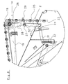
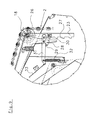
- stationary Deflection rollers 12 provided on an inwardly issued paragraph 12.1 of the sidewall housing parts 12.2 are arranged ( Figure 3 and 4).
- the housing expands, so that above the guide rollers 12 and the end portions of the bars 2.2 and the traction means 2.1 designed as a belt for the Bale forming device 2, a void is provided in the bale forming - in the Representation of Figure 4 thus up - can escape.
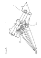
- the bale forming device 2 further has a generally numbered memory 14 Area which is supported via a guide roller 18 on a clamping arm 19. At this tension arm 19 attacks a designed as a spring 13 energy storage. Thus, the bale forming device Dodge 2 in this area. If the winding chamber 3 fills up, it will become one outward pressure exerted on the Lastrum 8 and the spring 13 compressed. It changes the located between the pulleys 18,19,21 length of the bale forming device. 2 The Erntegutballenveriererung goes hand in hand with an enlargement of the winding chamber.
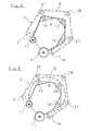
- bale start chamber formed, which is limited by the bale forming device polygons, as this also closer from Figure 5 of the drawings. This is the bale start process favored.
- the bale forming device takes the layers shown in Figures 1 and 5 and thus describes the apparent from this consistent and thus spatially determined Trajectory. It is about the first and second pulley 7 and 16 and the, to forming bale facing area over the stationary on the shoulder 12.1 of the side wall 12.2 arranged stationary rollers 12 out.
- the bale forming device 2 can continue with their load 8 expand, about the compression of the spring 13 and the compliance of the clamping arm 19th the trajectory of Ballenform drove the now expanding size in this subsequent bale forming phase, so that during this subsequent bale forming phase independent of the guide rollers 12, by the diameter of the bale to be formed certain other trajectories up to an adjustable bale diameter result.
- the outermost trajectory is in the FIG. 2 and illustrated in FIG.
- the bale to be formed can therefore have a diameter between the layers adjustable through the layers of Lastrums 8 of the bale forming device 2 - shown in Fig. 1 - and the position of Lastrums 8 of the bale forming device 2 - shown in Figure 2 - can vary as you like. Due to the resilient support of the guide roller 18 is during the further bale forming phase, a good contact between the bale forming device. 2 the drive roller 7 available to prevent slippage.
- An adjustable limiting device for specifying a diameter of the Erntegutballens is in the embodiment shown as a relative to the clamping arm 19 movable stop 22nd formed, which engages in a fixed housing abutment 24.
- a relative position of the Stop 22 to the clamping arm 19 i. depending on the angle between the longitudinal axis of the clamping arm 19 and the longitudinal axis of the stopper 22 is set, engages one of the shots of the Stop 22 in the abutment 24 and thus limits the effective length of Bale forming device 2, from the memory 14 to increase the winding chamber 3 for Is made available.
- Bale forming device 2 limits the effective length of Bale forming device 2 from the memory 14 to increase the winding chamber 3 for Is made available.
- Measuring device may be arranged to, for example, the Verdichtungssch the bale or the to control applied pressing force.
- deflection roller 18 in the direction of travel before rear end of the machine and behind the center of the forming crop bale arranged.
- the application of force to the tensioning arm 19 by the force accumulator designed as a spring 13 is thus approximately at right angles to the clamping arm 19, giving a favorable lever arm and thus a good transfer of applied forces brings with it.
- the spring 13 engages in the vicinity of the guide roller 18 on the clamping arm 19, and thus in an area in which the bale forming device 2 on the clamping arm 19 apply applied forces.
- the of the bale forming device 2 on the Guide roller 18 transmitted forces are on the stop 22 and the abutment 24 as well the tensioning arm 19 passed directly into the housing, which ensures a particularly firm support.
- the limiting element 23 relative to the clamping arm 19 can take the limiting element 23 enters the different, of the Noses 27 formed areas in abutment with the abutment 24. Accordingly different lengths of the bale forming device 2 released and it builds a pressing pressure only at different quasi maximum bale diameters.
- FIG. 7 shows an embodiment in which, in an alternative drive solution is possible, provided with an on-board hydraulic pump 34 machine 1 for recording and pressing of agricultural crop in case of overload in the drive ready to use.
- an on-board hydraulic pump 34 machine 1 for recording and pressing of agricultural crop in case of overload in the drive ready to use.
- the adjusting means additionally has a in the performance example described in FIG Actuator 28 with recesses 29 which, for a locking of the limiting element 23 in the described different angular positions with respect to the clamping arm 19 concern wear.
- a fastening 30, which is attached to the limiting element 23, releasably engages in the recesses 29 and thus locks the limiting element 23 in the various Positions.
- the abutment 24 further comprises a lever arm 31, which together with one on the housing fixed spring 32 forms the housing-fixed support.
- the spring 32 is a mobility ensures the lever arm 31, so that within a predetermined range with Help of mechanical, electromechanical or other means on the Emtegutballen acting pressing pressure can be determined and brought to the display.
- This serves For example, a uniform formation of Erntegutballens because the inventive Machine 1 in the direction of travel on both sides of the Erntegutballens the described actuating means with housing-fixed supports and thus has an indication of the on the various Side-loading pressure allows.
- a maximum position of the limiting element is shown 23, in which the abutment 24 is engaged with the top, through the nose 27 formed recess is.
- the limiting element 23 is located predominantly in an angular range of 90 ° to the clamping arm 19. This is between the Abutment point of the limiting element 23 on the abutment 24, the guide roller 18 and the Fulcrum of the clamping arm 19 ( Figure 1) formed a support triangle, which on the Deflection roller 18 force exerted by the bale forming device 2 in a perpendicular to the Transported abutment 24 and thus ensures optimal support security.
- the boundary element Therefore, it only has to be especially in the direction vertical to the ground be sustainable.
- the bale forming device 2 comprises transverse bars 2.2 whose Having multiply folded hollow sections and with not shown rivets with Strap 2.1 are connected.
- the strap 2.1 are made of a supple and yet little variable-length material to a good contact with the pulley To ensure 18 and thus to ensure optimum transmission of the forces to be supported.
Landscapes
- Life Sciences & Earth Sciences (AREA)
- Environmental Sciences (AREA)
- Storage Of Harvested Produce (AREA)
- Soil Working Implements (AREA)
- Harvester Elements (AREA)
- Harvesting Machines For Specific Crops (AREA)
- Sowing (AREA)
Abstract
Description
- Figur 1:
- Eine schematisch geschnittene Seitenansicht einer Maschine mit Darstellung einer Lage der Ballenformeinrichtung während der ersten Ballenformphase;
- Figur 2:
- eine zu Figur 1 analoge Darstellung mit Darstellung der Ballenformeinrichtung, die sich in ihrer Endlage in der Verdichtungsphase befindet;
- Figur 3:
- eine schematische perspektivische Darstellung der Ballenformeinrichtung, die in dem gezeigten Ausführungsbeispiel Umlenkrollen und an einem Absatz an den Seitenwandungsteilen der Maschine geführt ist und seitliche Riemen sowie Stäbe aufweist;
- Figur 4:
- eine Schnittdarstellung im Riemen- und Stabbereich in der Ballenformeinrichtung sowie durch eine ortsfeste Umlenkrolle in dem in Figur 3 gezeigten Gehäuseabsatz;
- Figuren 5 und 6:
- schematische Schnittdarstellungen der Lagen der Ballenformeinrichtung in den Stellungen, die in Figuren 1 und 2 darstellt sind,
- Figur 7:
- schematisch eine zusätzliche Ausführungsform mit einer von einer Sicherheitskupplung unabhängigen Hydraulikpumpe,
- Figur 8:
- ein Stellmittel eines Speichers der Ballenformeinrichtung in einer Stellung bei einem kleinen Erntegutballen und
- Figur 9:
- eine zu Fig. 8 analoge Darstellung bei einem großen Erntegutballen.
Claims (19)
- Maschine (1) zum Aufnehmen und Pressen von landwirtschaftlichem Erntegut wie beispielsweise Heu, Stroh, Gras oder dergleichen zu rollenförmigen Ballen mit einer aufklappbaren Wickelkammer (3), welche eine, einer Erntegutaufnahmevorrichtung (6) nachgeordnete Ballenformeinrichtung (2) aufweist, welche über zumindest eine erste und eine zweite ortsfeste Umlenkeinrichtung (7, 16) geführt ist und die während einer Ballenformphase innerhalb der Wickelkammer (3) eine räumlich bestimmte Bewegungsbahn auf Führungen (12) durchläuft und die zur Verdichtung des zu formenden Ballens nach Erreichen seines Maximaldurchmessers auf den Ballen eine Verdichtungskraft von außen nach innen ausübt, dadurch gekennzeichnet, dass die Ballenformeinrichtung (2) aus der räumlich bestimmten Bewegungsbahn während einer ersten Ballenformphase in einer nachfolgenden Ballenformphase in von den Führungen (12) unabhängige, durch den Durchmesser des zu formenden Ballens bestimmte weitere Bewegungsbahnen bis hin zu einem einstellbaren Ballendurchmesser überführbar ist, wobei der einstellbare maximale Ballendurchmesser durch bewegliche Stellmittel (22, 26, 23) wählbar ist und nach Erreichen des gewählten Ballendurchmessers die Verdichtung des zu formenden Ballens von außen nach innen als Ballenverdichtungsphase einleitbar ist.
- Maschine nach Anspruch 1, dadurch gekennzeichnet, dass die Stellmittel zur einstellbaren Begrenzung des maximalen Ballendurchmessers als mit zumindest einem Begrenzungselement (23) zusammenwirkende Anschläge (22, 26) ausgebildet sind.
- Maschine nach Anspruch 2, dadurch gekennzeichnet, dass das Begrenzungselement (23) an dem Maschinengehäuse angeordnet ist.
- Maschine nach einem der Ansprüche 2 oder 3, dadurch gekennzeichnet, dass die Stellmittel (22, 26) schwenkbar ausgebildet sind.
- Maschine nach einem der Ansprüche 1 bis 4, dadurch gekennzeichnet, dass die zwischen der ersten und der zweiten Umlenkeinrichtung (7, 16) vorgesehenen Führungen ortfeste Seitenwandführungen (12.1) eines Gehäuses der Maschine umfassen.
- Maschine nach einem der Ansprüche 1 bis 5, dadurch gekennzeichnet, dass die Wickelkammer (3) durch Gehäusewandungsteile (12.2) begrenzt ist, die die Seitenwandführungen (12.1) aufweisen.
- Maschine nach Anspruch 5 oder 6, dadurch gekennzeichnet, dass die seitlichen Gehäusewandungen (12.2) des Wickelraumes (3) mit einem nach innen ausgestellten Absatz als ortsfeste Seitenwandführungen (12.1) für die räumlich bestimmte Bewegungsbahn der Ballenformeinrichtung (2) ausgebildet sind.
- Maschine nach einem der Ansprüche 5 bis 7, dadurch gekennzeichnet, dass die ortsfesten Seitenwandführungen (12.1) ortsfest abgestützte Umlenkrollen (12) aufweisen.
- Maschine nach einem der Ansprüche 1 bis 8, dadurch gekennzeichnet, dass die Ballenformeinrichtung (2) endseitig an Zugmitteln (2.1) festgelegte Querstäbe (2.2) aufweist.
- Maschine nach einem der Ansprüche 1 bis 9, dadurch gekennzeichnet, dass die erste und die zweite Umlenkeinrichtung (7, 16) als in dem Ballenformraum (3) angeordnete obere und untere ortsfeste Umlenkrollen ausgebildet sind, und die untere ortsfeste Umlenkrolle (16) unmittelbar einem Förderelement (11) der Erntegutaufnahmevorrichtung (6) nachgeordnet ist.
- Maschine nach Anspruch 10, dadurch gekennzeichnet, dass das Förderelement (11) der unteren Umlenkrolle (16) derart vorgeordnet ist, dass das geförderte Erntegut von oben der durch die untere Umlenkrolle (16) umgelenkten Ballenformeinrichtung (2) zugeführt wird.
- Maschine nach einem der Ansprüche 1 bis 11, dadurch gekennzeichnet, dass die Ballenformeinrichtung (2) während einer ersten Ballenformphase derart an den Führungen (12) und den ortsfesten Seitenwandführungen (12.1) geführt ist, daß eine mehreckige, aber einer kreisrunden Form angenäherte Ballenstartkammer ausgebildet ist.
- Maschine nach Anspruch 12, dadurch gekennzeichnet, dass dei Ballenstartkammer dreieckförmig, viereckförmig oder fünfeckförmig ausgebildet ist.
- Maschine nach einem der Ansprüche 1 bis 13, dadurch gekennzeichnet, dass die Führungen (12) außerhalb der den Wickelraum (3) während der ersten Ballenformphase seitlich begrenzenden Gehäusewandung (12.3) angeordnet sind.
- Maschine nach einem der Ansprüche 1 bis 14, dadurch gekennzeichnet, dass sich die Querstäbe (2.2) der Ballenformeinrichtung (2) über die Breite des Ballenformraumes während der ersten Ballenformphase hinaus erstrecken.
- Maschine nach einem der Ansprüche 1 bis 15, dadurch gekennzeichnet, dass mit Einleitung der Ballenverdichtungsphase Messelemente zur Bestimmung einer Ballenkennung wie z.B. Ballenfestigkeit oder dgl. aktivierbar sind.
- Maschine nach einem der Ansprüche 1 bis 16, dadurch gekennzeichnet, dass eine von einer Überlastsicherung (25) unabhängige Hydraulikpumpe (34) vorgesehen ist, die im Überlastfall für den Betrieb eines Maschinenaggregates ausgebildet ist.
- Maschine nach einem der Ansprüche 1 bis 16, dadurch gekennzeichnet, dass die Ballenformeinrichtung (2) über eine Umlenkrollen (18), die von Kraftspeichern belastbar sind, nachgiebig abstützbar ist.
- Maschine nach Anspruch 18, dadurch gekennzeichnet, dass die Kraftspeicher als Federn (13) ausgebildet sind.
Priority Applications (1)
| Application Number | Priority Date | Filing Date | Title |
|---|---|---|---|
| PL05009887T PL1595438T3 (pl) | 2004-05-11 | 2005-05-06 | Maszyna do przyjmowania i prasowania rolniczego materiału żniwnego |
Applications Claiming Priority (2)
| Application Number | Priority Date | Filing Date | Title |
|---|---|---|---|
| DE102004023696 | 2004-05-11 | ||
| DE102004023696A DE102004023696B4 (de) | 2004-05-11 | 2004-05-11 | Maschine zum Aufnehmen und Pressen von landwirtschaftlichem Erntegut |
Publications (2)
| Publication Number | Publication Date |
|---|---|
| EP1595438A1 true EP1595438A1 (de) | 2005-11-16 |
| EP1595438B1 EP1595438B1 (de) | 2008-12-31 |
Family
ID=34977039
Family Applications (1)
| Application Number | Title | Priority Date | Filing Date |
|---|---|---|---|
| EP05009887A Expired - Lifetime EP1595438B1 (de) | 2004-05-11 | 2005-05-06 | Maschine zum Aufnehmen und Pressen von landwirtschaftlichem Erntegut |
Country Status (6)
| Country | Link |
|---|---|
| US (1) | US7181899B2 (de) |
| EP (1) | EP1595438B1 (de) |
| AT (1) | ATE418857T1 (de) |
| DE (2) | DE102004023696B4 (de) |
| EA (1) | EA007819B1 (de) |
| PL (1) | PL1595438T3 (de) |
Cited By (1)
| Publication number | Priority date | Publication date | Assignee | Title |
|---|---|---|---|---|
| EP2392206A1 (de) | 2010-06-01 | 2011-12-07 | Deere & Company | Rundballenpresse |
Families Citing this family (12)
| Publication number | Priority date | Publication date | Assignee | Title |
|---|---|---|---|---|
| DE102007041634A1 (de) | 2007-09-03 | 2009-03-05 | Schütte, Thomas | Rundballenpresse mit aufklappbarer variabler Ballenkammer und Verfahren zum Pressen von Rundballen |
| US8800255B2 (en) * | 2011-07-01 | 2014-08-12 | Cnh Industrial America Llc | Arrangement and control of precompression rolls in balers |
| US8820040B2 (en) * | 2011-07-01 | 2014-09-02 | Cnh Industrial America Llc | Compression rolls on baler pick up |
| DE102011111401B4 (de) | 2011-08-10 | 2013-09-26 | Maschinenfabrik Bernard Krone Gmbh | Landwirtschaftliche Rundballenpresse |
| DE102011109899B4 (de) | 2011-08-10 | 2013-02-21 | Maschinenfabrik Bernard Krone Gmbh | Landwirtschaftliche Rundballenpresse |
| DE102011109890B4 (de) | 2011-08-10 | 2013-07-04 | Maschinenfabrik Bernard Krone Gmbh | Landwirtschaftliche Rundballenpresse |
| DE102011109891B4 (de) | 2011-08-10 | 2013-05-29 | Maschinenfabrik Bernard Krone Gmbh | Landwirtschaftliche Rundballenpresse |
| DE102011109893A1 (de) | 2011-08-10 | 2013-02-14 | Maschinenfabrik Bernard Krone Gmbh | Landwirtschaftliche Rundballenpresse |
| DE102012002796A1 (de) * | 2012-02-15 | 2013-08-22 | Usines Claas France S.A.S. | Ballenpresse |
| DE102016002144A1 (de) * | 2016-02-25 | 2017-08-31 | Maschinenfabrik Krone Beteiligungs-GmbH | Fördergurt und landwirtschaftliche Erntemaschinen mit einem Fördergurt |
| EA034402B1 (ru) * | 2018-05-16 | 2020-02-04 | Павел Валерьевич Шаплыко | Способ повышения плотности рулона растительной массы и устройство прессования рулонов повышенной плотности |
| DE102023113954A1 (de) * | 2023-05-26 | 2024-11-28 | Maschinenfabrik Bernard Krone GmbH & Co. KG | Getriebeeinheit |
Citations (4)
| Publication number | Priority date | Publication date | Assignee | Title |
|---|---|---|---|---|
| US3901007A (en) * | 1973-04-24 | 1975-08-26 | Sperry Rand Corp | Hay roll forming machine |
| US4121513A (en) * | 1976-07-12 | 1978-10-24 | Kopaska Arnold F | Machine for rolling crops into round bales |
| FR2647630A1 (fr) * | 1989-06-06 | 1990-12-07 | Claas Ohg | Presse a balles rondes pour produits de recoltes agricoles |
| WO1997003550A1 (en) * | 1995-07-24 | 1997-02-06 | Antonio Feraboli | Variable chamber round baler having a bale core formation chamber with a variable geometry |
Family Cites Families (13)
| Publication number | Priority date | Publication date | Assignee | Title |
|---|---|---|---|---|
| US4257219A (en) * | 1979-08-27 | 1981-03-24 | Gehl Company | Cylindrical bale forming machine having hydraulic control means for controlling the bale density |
| US4389929A (en) * | 1981-07-13 | 1983-06-28 | The Paul Revere Corporation | Latching mechanism for a round baler |
| GB8308564D0 (en) * | 1983-03-29 | 1983-05-05 | Sperry Nv | Agricultural balers |
| NL8301647A (nl) * | 1983-05-09 | 1984-12-03 | Multinorm Bv | Inrichting voor het tot een ronde baal vormen van gewas. |
| SU1387909A1 (ru) * | 1986-04-22 | 1988-04-15 | В.И.Шумейко и Н.П.Шумейко | Способ заготовки корма и пресс-подборщик |
| SU1428277A1 (ru) * | 1987-03-12 | 1988-10-07 | Фрунзенский Конструкторско-Технологический Институт По Кормоуборочным Машинам | Рулонный пресс-подборщик |
| SU1759307A1 (ru) * | 1990-02-13 | 1992-09-07 | Всесоюзный Научно-Исследовательский Институт Комплексных Проблем Машиностроения Для Животноводства И Кормопроизводства | Рулонный пресс-подборщик |
| US5138942A (en) * | 1991-01-28 | 1992-08-18 | Gehl Company | Belt type round baler with adjustable bale starting chamber |
| SE9302191L (sv) * | 1993-06-24 | 1994-12-19 | Bala Ind Ab | Anordning vid rund balningsanläggning |
| US5444969A (en) * | 1993-07-12 | 1995-08-29 | New Holland North America, Inc. | Round baler apparatus for monitoring bale shape |
| DE29814775U1 (de) * | 1998-08-18 | 1998-11-12 | Usines Claas France, Woippy | Rundballenpresse |
| RU2186480C2 (ru) * | 2000-04-12 | 2002-08-10 | Закрытое акционерное общество "Завод Бежецксельмаш" | Рулонный пресс-подборщик |
| DE10223417A1 (de) * | 2002-05-25 | 2003-12-24 | Lely Maschinenfabrik Gmbh | Rundballenpresse für landwirtschaftliche Halmgüter |
-
2004
- 2004-05-11 DE DE102004023696A patent/DE102004023696B4/de not_active Expired - Fee Related
-
2005
- 2005-05-06 DE DE502005006354T patent/DE502005006354D1/de not_active Expired - Lifetime
- 2005-05-06 EP EP05009887A patent/EP1595438B1/de not_active Expired - Lifetime
- 2005-05-06 EA EA200500620A patent/EA007819B1/ru active IP Right Revival
- 2005-05-06 AT AT05009887T patent/ATE418857T1/de active
- 2005-05-06 PL PL05009887T patent/PL1595438T3/pl unknown
- 2005-05-10 US US10/908,386 patent/US7181899B2/en not_active Expired - Lifetime
Patent Citations (4)
| Publication number | Priority date | Publication date | Assignee | Title |
|---|---|---|---|---|
| US3901007A (en) * | 1973-04-24 | 1975-08-26 | Sperry Rand Corp | Hay roll forming machine |
| US4121513A (en) * | 1976-07-12 | 1978-10-24 | Kopaska Arnold F | Machine for rolling crops into round bales |
| FR2647630A1 (fr) * | 1989-06-06 | 1990-12-07 | Claas Ohg | Presse a balles rondes pour produits de recoltes agricoles |
| WO1997003550A1 (en) * | 1995-07-24 | 1997-02-06 | Antonio Feraboli | Variable chamber round baler having a bale core formation chamber with a variable geometry |
Cited By (2)
| Publication number | Priority date | Publication date | Assignee | Title |
|---|---|---|---|---|
| EP2392206A1 (de) | 2010-06-01 | 2011-12-07 | Deere & Company | Rundballenpresse |
| US8499686B2 (en) | 2010-06-01 | 2013-08-06 | Deere & Company | Round baler |
Also Published As
| Publication number | Publication date |
|---|---|
| US7181899B2 (en) | 2007-02-27 |
| EP1595438B1 (de) | 2008-12-31 |
| EA007819B1 (ru) | 2007-02-27 |
| ATE418857T1 (de) | 2009-01-15 |
| PL1595438T3 (pl) | 2009-06-30 |
| EA200500620A1 (ru) | 2005-12-29 |
| DE502005006354D1 (de) | 2009-02-12 |
| US20050252389A1 (en) | 2005-11-17 |
| DE102004023696B4 (de) | 2007-03-29 |
| DE102004023696A1 (de) | 2005-12-08 |
Similar Documents
| Publication | Publication Date | Title |
|---|---|---|
| EP0157898B1 (de) | Vorrichtung zum Binden von Rollballen aus landwirtschaftlichem Erntegut | |
| EP4108069B1 (de) | Rundballenpresse | |
| DE2801309C2 (de) | ||
| DE2443838A1 (de) | Rollballenpresse | |
| EP1595438A1 (de) | Maschine zum Aufnehmen und Pressen von landwirtschaftlichem Entegut | |
| EP1969918B1 (de) | Rundballenpresse und Verfahren zur Änderung der Reibung an deren Seitenwänden | |
| DE10063121A1 (de) | Rundballenpresse | |
| DE602004009666T2 (de) | Rundballenpresse | |
| EP1308078A1 (de) | Rundballenpresse | |
| DE2947442C2 (de) | ||
| DE10224394A1 (de) | Rundballenpresse | |
| DE1577284A1 (de) | Wickelpresse fuer Futterpresslinge | |
| EP0894428B1 (de) | Rundballenpresse | |
| EP0095689B1 (de) | Rundballenpresse mit einem einen Guteinlass aufweisenden Ballenpressraum | |
| DE102004023694B4 (de) | Maschine zum Aufnehmen und Pressen von landwirtschaftlichem Erntegut | |
| EP1214876A1 (de) | Bodenförderer für eine Rundballenpresse | |
| EP3459341A1 (de) | Landwirtschaftliche rundballenpresse | |
| DE10145690A1 (de) | Ballenpresse | |
| DE10335883A1 (de) | Rundballenpresse | |
| EP1982576B1 (de) | Ballenpresse mit Knotereinrichtung | |
| DE19705582A1 (de) | Rundballenpresse | |
| DE102004023703B4 (de) | Maschine zum Aufnehmen und Pressen von landwirtschaftlichem Erntegut | |
| EP1595441B1 (de) | Maschine zum Aufnehmen und Pressen von landwirtschaftlichem Erntegut | |
| DE102005036181A1 (de) | Rundballenpresse | |
| DE10257084A1 (de) | Rundballenpresse |
Legal Events
| Date | Code | Title | Description |
|---|---|---|---|
| PUAI | Public reference made under article 153(3) epc to a published international application that has entered the european phase |
Free format text: ORIGINAL CODE: 0009012 |
|
| AK | Designated contracting states |
Kind code of ref document: A1 Designated state(s): AT BE BG CH CY CZ DE DK EE ES FI FR GB GR HU IE IS IT LI LT LU MC NL PL PT RO SE SI SK TR |
|
| AX | Request for extension of the european patent |
Extension state: AL BA HR LV MK YU |
|
| 17P | Request for examination filed |
Effective date: 20060515 |
|
| AKX | Designation fees paid |
Designated state(s): AT BE BG CH CY CZ DE DK EE ES FI FR GB GR HU IE IS IT LI LT LU MC NL PL PT RO SE SI SK TR |
|
| 17Q | First examination report despatched |
Effective date: 20070228 |
|
| GRAP | Despatch of communication of intention to grant a patent |
Free format text: ORIGINAL CODE: EPIDOSNIGR1 |
|
| GRAS | Grant fee paid |
Free format text: ORIGINAL CODE: EPIDOSNIGR3 |
|
| GRAA | (expected) grant |
Free format text: ORIGINAL CODE: 0009210 |
|
| AK | Designated contracting states |
Kind code of ref document: B1 Designated state(s): AT BE BG CH CY CZ DE DK EE ES FI FR GB GR HU IE IS IT LI LT LU MC NL PL PT RO SE SI SK TR |
|
| REG | Reference to a national code |
Ref country code: GB Ref legal event code: FG4D Free format text: NOT ENGLISH Ref country code: CH Ref legal event code: EP |
|
| REF | Corresponds to: |
Ref document number: 502005006354 Country of ref document: DE Date of ref document: 20090212 Kind code of ref document: P |
|
| REG | Reference to a national code |
Ref country code: DE Ref legal event code: R096 Ref document number: 502005006354 Country of ref document: DE Effective date: 20090212 |
|
| REG | Reference to a national code |
Ref country code: IE Ref legal event code: FG4D Free format text: LANGUAGE OF EP DOCUMENT: GERMAN |
|
| PG25 | Lapsed in a contracting state [announced via postgrant information from national office to epo] |
Ref country code: SI Free format text: LAPSE BECAUSE OF FAILURE TO SUBMIT A TRANSLATION OF THE DESCRIPTION OR TO PAY THE FEE WITHIN THE PRESCRIBED TIME-LIMIT Effective date: 20081231 |
|
| REG | Reference to a national code |
Ref country code: PL Ref legal event code: T3 |
|
| PG25 | Lapsed in a contracting state [announced via postgrant information from national office to epo] |
Ref country code: RO Free format text: LAPSE BECAUSE OF FAILURE TO SUBMIT A TRANSLATION OF THE DESCRIPTION OR TO PAY THE FEE WITHIN THE PRESCRIBED TIME-LIMIT Effective date: 20081231 Ref country code: EE Free format text: LAPSE BECAUSE OF FAILURE TO SUBMIT A TRANSLATION OF THE DESCRIPTION OR TO PAY THE FEE WITHIN THE PRESCRIBED TIME-LIMIT Effective date: 20081231 Ref country code: ES Free format text: LAPSE BECAUSE OF FAILURE TO SUBMIT A TRANSLATION OF THE DESCRIPTION OR TO PAY THE FEE WITHIN THE PRESCRIBED TIME-LIMIT Effective date: 20090411 Ref country code: LT Free format text: LAPSE BECAUSE OF FAILURE TO SUBMIT A TRANSLATION OF THE DESCRIPTION OR TO PAY THE FEE WITHIN THE PRESCRIBED TIME-LIMIT Effective date: 20081231 |
|
| PG25 | Lapsed in a contracting state [announced via postgrant information from national office to epo] |
Ref country code: CZ Free format text: LAPSE BECAUSE OF FAILURE TO SUBMIT A TRANSLATION OF THE DESCRIPTION OR TO PAY THE FEE WITHIN THE PRESCRIBED TIME-LIMIT Effective date: 20081231 Ref country code: SE Free format text: LAPSE BECAUSE OF FAILURE TO SUBMIT A TRANSLATION OF THE DESCRIPTION OR TO PAY THE FEE WITHIN THE PRESCRIBED TIME-LIMIT Effective date: 20090331 Ref country code: PT Free format text: LAPSE BECAUSE OF FAILURE TO SUBMIT A TRANSLATION OF THE DESCRIPTION OR TO PAY THE FEE WITHIN THE PRESCRIBED TIME-LIMIT Effective date: 20090601 Ref country code: IS Free format text: LAPSE BECAUSE OF FAILURE TO SUBMIT A TRANSLATION OF THE DESCRIPTION OR TO PAY THE FEE WITHIN THE PRESCRIBED TIME-LIMIT Effective date: 20090430 |
|
| PG25 | Lapsed in a contracting state [announced via postgrant information from national office to epo] |
Ref country code: SK Free format text: LAPSE BECAUSE OF FAILURE TO SUBMIT A TRANSLATION OF THE DESCRIPTION OR TO PAY THE FEE WITHIN THE PRESCRIBED TIME-LIMIT Effective date: 20081231 |
|
| PG25 | Lapsed in a contracting state [announced via postgrant information from national office to epo] |
Ref country code: DK Free format text: LAPSE BECAUSE OF FAILURE TO SUBMIT A TRANSLATION OF THE DESCRIPTION OR TO PAY THE FEE WITHIN THE PRESCRIBED TIME-LIMIT Effective date: 20081231 |
|
| PLBE | No opposition filed within time limit |
Free format text: ORIGINAL CODE: 0009261 |
|
| STAA | Information on the status of an ep patent application or granted ep patent |
Free format text: STATUS: NO OPPOSITION FILED WITHIN TIME LIMIT |
|
| 26N | No opposition filed |
Effective date: 20091001 |
|
| PG25 | Lapsed in a contracting state [announced via postgrant information from national office to epo] |
Ref country code: MC Free format text: LAPSE BECAUSE OF NON-PAYMENT OF DUE FEES Effective date: 20090531 |
|
| REG | Reference to a national code |
Ref country code: CH Ref legal event code: PL |
|
| REG | Reference to a national code |
Ref country code: DE Ref legal event code: R097 Ref document number: 502005006354 Country of ref document: DE Effective date: 20091001 |
|
| GBPC | Gb: european patent ceased through non-payment of renewal fee |
Effective date: 20090506 |
|
| PG25 | Lapsed in a contracting state [announced via postgrant information from national office to epo] |
Ref country code: BG Free format text: LAPSE BECAUSE OF FAILURE TO SUBMIT A TRANSLATION OF THE DESCRIPTION OR TO PAY THE FEE WITHIN THE PRESCRIBED TIME-LIMIT Effective date: 20090331 Ref country code: LI Free format text: LAPSE BECAUSE OF NON-PAYMENT OF DUE FEES Effective date: 20090531 Ref country code: CH Free format text: LAPSE BECAUSE OF NON-PAYMENT OF DUE FEES Effective date: 20090531 |
|
| PG25 | Lapsed in a contracting state [announced via postgrant information from national office to epo] |
Ref country code: GB Free format text: LAPSE BECAUSE OF NON-PAYMENT OF DUE FEES Effective date: 20090506 |
|
| PG25 | Lapsed in a contracting state [announced via postgrant information from national office to epo] |
Ref country code: GR Free format text: LAPSE BECAUSE OF FAILURE TO SUBMIT A TRANSLATION OF THE DESCRIPTION OR TO PAY THE FEE WITHIN THE PRESCRIBED TIME-LIMIT Effective date: 20090401 |
|
| PG25 | Lapsed in a contracting state [announced via postgrant information from national office to epo] |
Ref country code: LU Free format text: LAPSE BECAUSE OF NON-PAYMENT OF DUE FEES Effective date: 20090506 |
|
| PG25 | Lapsed in a contracting state [announced via postgrant information from national office to epo] |
Ref country code: HU Free format text: LAPSE BECAUSE OF FAILURE TO SUBMIT A TRANSLATION OF THE DESCRIPTION OR TO PAY THE FEE WITHIN THE PRESCRIBED TIME-LIMIT Effective date: 20090701 |
|
| PG25 | Lapsed in a contracting state [announced via postgrant information from national office to epo] |
Ref country code: TR Free format text: LAPSE BECAUSE OF FAILURE TO SUBMIT A TRANSLATION OF THE DESCRIPTION OR TO PAY THE FEE WITHIN THE PRESCRIBED TIME-LIMIT Effective date: 20081231 |
|
| PG25 | Lapsed in a contracting state [announced via postgrant information from national office to epo] |
Ref country code: CY Free format text: LAPSE BECAUSE OF FAILURE TO SUBMIT A TRANSLATION OF THE DESCRIPTION OR TO PAY THE FEE WITHIN THE PRESCRIBED TIME-LIMIT Effective date: 20081231 |
|
| REG | Reference to a national code |
Ref country code: FR Ref legal event code: PLFP Year of fee payment: 12 |
|
| REG | Reference to a national code |
Ref country code: FR Ref legal event code: PLFP Year of fee payment: 13 |
|
| REG | Reference to a national code |
Ref country code: FR Ref legal event code: PLFP Year of fee payment: 14 |
|
| REG | Reference to a national code |
Ref country code: BE Ref legal event code: HC Owner name: MASCHINENFABRIK BERNARD KRONE GMBH & CO. KG; DE Free format text: DETAILS ASSIGNMENT: CHANGE OF OWNER(S), CHANGE OF OWNER(S) NAME Effective date: 20210209 |
|
| PGFP | Annual fee paid to national office [announced via postgrant information from national office to epo] |
Ref country code: NL Payment date: 20210519 Year of fee payment: 17 Ref country code: IT Payment date: 20210531 Year of fee payment: 17 Ref country code: FR Payment date: 20210521 Year of fee payment: 17 Ref country code: FI Payment date: 20210518 Year of fee payment: 17 |
|
| PGFP | Annual fee paid to national office [announced via postgrant information from national office to epo] |
Ref country code: IE Payment date: 20210519 Year of fee payment: 17 Ref country code: BE Payment date: 20210519 Year of fee payment: 17 Ref country code: AT Payment date: 20210518 Year of fee payment: 17 |
|
| REG | Reference to a national code |
Ref country code: DE Ref legal event code: R081 Ref document number: 502005006354 Country of ref document: DE Owner name: KRONE AGRICULTURE SE, DE Free format text: FORMER OWNER: MASCHINENFABRIK BERNARD KRONE GMBH, 48480 SPELLE, DE |
|
| REG | Reference to a national code |
Ref country code: FI Ref legal event code: PCE Owner name: KRONE AGRICULTURE SE |
|
| REG | Reference to a national code |
Ref country code: AT Ref legal event code: PC Ref document number: 418857 Country of ref document: AT Kind code of ref document: T Owner name: KRONE AGRICULTURE SE, DE Effective date: 20211022 |
|
| REG | Reference to a national code |
Ref country code: NL Ref legal event code: PD Owner name: KRONE AGRICULTURE SE; DE Free format text: DETAILS ASSIGNMENT: CHANGE OF OWNER(S), MERGE; FORMER OWNER NAME: MASCHINENFABRIK KRONE BETEILIGUNGS-GMBH Effective date: 20211126 Ref country code: NL Ref legal event code: HC Owner name: MASCHINENFABRIK KRONE BETEILIGUNGS-GMBH; DE Free format text: DETAILS ASSIGNMENT: CHANGE OF OWNER(S), CHANGE OF OWNER(S) NAME; FORMER OWNER NAME: MASCHINENFABRIK BERNARD KRONE GMBH Effective date: 20211126 |
|
| REG | Reference to a national code |
Ref country code: DE Ref legal event code: R084 Ref document number: 502005006354 Country of ref document: DE |
|
| REG | Reference to a national code |
Ref country code: NL Ref legal event code: MM Effective date: 20220601 |
|
| REG | Reference to a national code |
Ref country code: AT Ref legal event code: MM01 Ref document number: 418857 Country of ref document: AT Kind code of ref document: T Effective date: 20220506 |
|
| REG | Reference to a national code |
Ref country code: BE Ref legal event code: MM Effective date: 20220531 |
|
| PG25 | Lapsed in a contracting state [announced via postgrant information from national office to epo] |
Ref country code: FI Free format text: LAPSE BECAUSE OF NON-PAYMENT OF DUE FEES Effective date: 20220506 Ref country code: AT Free format text: LAPSE BECAUSE OF NON-PAYMENT OF DUE FEES Effective date: 20220506 |
|
| PG25 | Lapsed in a contracting state [announced via postgrant information from national office to epo] |
Ref country code: IE Free format text: LAPSE BECAUSE OF NON-PAYMENT OF DUE FEES Effective date: 20220506 Ref country code: FR Free format text: LAPSE BECAUSE OF NON-PAYMENT OF DUE FEES Effective date: 20220531 |
|
| PG25 | Lapsed in a contracting state [announced via postgrant information from national office to epo] |
Ref country code: BE Free format text: LAPSE BECAUSE OF NON-PAYMENT OF DUE FEES Effective date: 20220531 |
|
| P01 | Opt-out of the competence of the unified patent court (upc) registered |
Effective date: 20230517 |
|
| PG25 | Lapsed in a contracting state [announced via postgrant information from national office to epo] |
Ref country code: NL Free format text: LAPSE BECAUSE OF NON-PAYMENT OF DUE FEES Effective date: 20220601 |
|
| PG25 | Lapsed in a contracting state [announced via postgrant information from national office to epo] |
Ref country code: IT Free format text: LAPSE BECAUSE OF NON-PAYMENT OF DUE FEES Effective date: 20220506 |
|
| PGFP | Annual fee paid to national office [announced via postgrant information from national office to epo] |
Ref country code: DE Payment date: 20230519 Year of fee payment: 19 |
|
| PGFP | Annual fee paid to national office [announced via postgrant information from national office to epo] |
Ref country code: PL Payment date: 20230425 Year of fee payment: 19 |
|
| REG | Reference to a national code |
Ref country code: DE Ref legal event code: R119 Ref document number: 502005006354 Country of ref document: DE |
|
| PG25 | Lapsed in a contracting state [announced via postgrant information from national office to epo] |
Ref country code: DE Free format text: LAPSE BECAUSE OF NON-PAYMENT OF DUE FEES Effective date: 20241203 |
|
| PG25 | Lapsed in a contracting state [announced via postgrant information from national office to epo] |
Ref country code: PL Free format text: LAPSE BECAUSE OF NON-PAYMENT OF DUE FEES Effective date: 20240506 |