EP2850308B1 - Sauerstoffsensor und diesen aufweisende brennkraftmaschine - Google Patents
Sauerstoffsensor und diesen aufweisende brennkraftmaschine Download PDFInfo
- Publication number
- EP2850308B1 EP2850308B1 EP13719465.0A EP13719465A EP2850308B1 EP 2850308 B1 EP2850308 B1 EP 2850308B1 EP 13719465 A EP13719465 A EP 13719465A EP 2850308 B1 EP2850308 B1 EP 2850308B1
- Authority
- EP
- European Patent Office
- Prior art keywords
- sensor
- internal combustion
- combustion engine
- sensor element
- intake tract
- Prior art date
- Legal status (The legal status is an assumption and is not a legal conclusion. Google has not performed a legal analysis and makes no representation as to the accuracy of the status listed.)
- Not-in-force
Links
Images
Classifications
-
- G—PHYSICS
- G01—MEASURING; TESTING
- G01N—INVESTIGATING OR ANALYSING MATERIALS BY DETERMINING THEIR CHEMICAL OR PHYSICAL PROPERTIES
- G01N27/00—Investigating or analysing materials by the use of electric, electrochemical, or magnetic means
- G01N27/26—Investigating or analysing materials by the use of electric, electrochemical, or magnetic means by investigating electrochemical variables; by using electrolysis or electrophoresis
- G01N27/403—Cells and electrode assemblies
- G01N27/406—Cells and probes with solid electrolytes
- G01N27/407—Cells and probes with solid electrolytes for investigating or analysing gases
- G01N27/4077—Means for protecting the electrolyte or the electrodes
-
- F—MECHANICAL ENGINEERING; LIGHTING; HEATING; WEAPONS; BLASTING
- F02—COMBUSTION ENGINES; HOT-GAS OR COMBUSTION-PRODUCT ENGINE PLANTS
- F02D—CONTROLLING COMBUSTION ENGINES
- F02D41/00—Electrical control of supply of combustible mixture or its constituents
- F02D41/02—Circuit arrangements for generating control signals
- F02D41/14—Introducing closed-loop corrections
- F02D41/1438—Introducing closed-loop corrections using means for determining characteristics of the combustion gases; Sensors therefor
- F02D41/1439—Introducing closed-loop corrections using means for determining characteristics of the combustion gases; Sensors therefor characterised by the position of the sensor
- F02D41/144—Sensor in intake manifold
-
- F—MECHANICAL ENGINEERING; LIGHTING; HEATING; WEAPONS; BLASTING
- F02—COMBUSTION ENGINES; HOT-GAS OR COMBUSTION-PRODUCT ENGINE PLANTS
- F02M—SUPPLYING COMBUSTION ENGINES IN GENERAL WITH COMBUSTIBLE MIXTURES OR CONSTITUENTS THEREOF
- F02M26/00—Engine-pertinent apparatus for adding exhaust gases to combustion-air, main fuel or fuel-air mixture, e.g. by exhaust gas recirculation [EGR] systems
- F02M26/13—Arrangement or layout of EGR passages, e.g. in relation to specific engine parts or for incorporation of accessories
- F02M26/22—Arrangement or layout of EGR passages, e.g. in relation to specific engine parts or for incorporation of accessories with coolers in the recirculation passage
-
- F—MECHANICAL ENGINEERING; LIGHTING; HEATING; WEAPONS; BLASTING
- F02—COMBUSTION ENGINES; HOT-GAS OR COMBUSTION-PRODUCT ENGINE PLANTS
- F02M—SUPPLYING COMBUSTION ENGINES IN GENERAL WITH COMBUSTIBLE MIXTURES OR CONSTITUENTS THEREOF
- F02M26/00—Engine-pertinent apparatus for adding exhaust gases to combustion-air, main fuel or fuel-air mixture, e.g. by exhaust gas recirculation [EGR] systems
- F02M26/45—Sensors specially adapted for EGR systems
-
- F—MECHANICAL ENGINEERING; LIGHTING; HEATING; WEAPONS; BLASTING
- F02—COMBUSTION ENGINES; HOT-GAS OR COMBUSTION-PRODUCT ENGINE PLANTS
- F02M—SUPPLYING COMBUSTION ENGINES IN GENERAL WITH COMBUSTIBLE MIXTURES OR CONSTITUENTS THEREOF
- F02M35/00—Combustion-air cleaners, air intakes, intake silencers, or induction systems specially adapted for, or arranged on, internal-combustion engines
- F02M35/10—Air intakes; Induction systems
- F02M35/10373—Sensors for intake systems
-
- F—MECHANICAL ENGINEERING; LIGHTING; HEATING; WEAPONS; BLASTING
- F02—COMBUSTION ENGINES; HOT-GAS OR COMBUSTION-PRODUCT ENGINE PLANTS
- F02D—CONTROLLING COMBUSTION ENGINES
- F02D41/00—Electrical control of supply of combustible mixture or its constituents
- F02D41/24—Electrical control of supply of combustible mixture or its constituents characterised by the use of digital means
- F02D41/26—Electrical control of supply of combustible mixture or its constituents characterised by the use of digital means using computer, e.g. microprocessor
- F02D41/28—Interface circuits
- F02D2041/281—Interface circuits between sensors and control unit
- F02D2041/285—Interface circuits between sensors and control unit the sensor having a signal processing unit external to the engine control unit
-
- F—MECHANICAL ENGINEERING; LIGHTING; HEATING; WEAPONS; BLASTING
- F02—COMBUSTION ENGINES; HOT-GAS OR COMBUSTION-PRODUCT ENGINE PLANTS
- F02D—CONTROLLING COMBUSTION ENGINES
- F02D2200/00—Input parameters for engine control
- F02D2200/02—Input parameters for engine control the parameters being related to the engine
- F02D2200/04—Engine intake system parameters
- F02D2200/0406—Intake manifold pressure
-
- F—MECHANICAL ENGINEERING; LIGHTING; HEATING; WEAPONS; BLASTING
- F02—COMBUSTION ENGINES; HOT-GAS OR COMBUSTION-PRODUCT ENGINE PLANTS
- F02D—CONTROLLING COMBUSTION ENGINES
- F02D41/00—Electrical control of supply of combustible mixture or its constituents
- F02D41/0025—Controlling engines characterised by use of non-liquid fuels, pluralities of fuels, or non-fuel substances added to the combustible mixtures
- F02D41/0047—Controlling exhaust gas recirculation [EGR]
- F02D41/0065—Specific aspects of external EGR control
- F02D41/0072—Estimating, calculating or determining the EGR rate, amount or flow
-
- F—MECHANICAL ENGINEERING; LIGHTING; HEATING; WEAPONS; BLASTING
- F02—COMBUSTION ENGINES; HOT-GAS OR COMBUSTION-PRODUCT ENGINE PLANTS
- F02D—CONTROLLING COMBUSTION ENGINES
- F02D41/00—Electrical control of supply of combustible mixture or its constituents
- F02D41/02—Circuit arrangements for generating control signals
- F02D41/14—Introducing closed-loop corrections
- F02D41/1438—Introducing closed-loop corrections using means for determining characteristics of the combustion gases; Sensors therefor
- F02D41/1444—Introducing closed-loop corrections using means for determining characteristics of the combustion gases; Sensors therefor characterised by the characteristics of the combustion gases
- F02D41/1454—Introducing closed-loop corrections using means for determining characteristics of the combustion gases; Sensors therefor characterised by the characteristics of the combustion gases the characteristics being an oxygen content or concentration or the air-fuel ratio
-
- F—MECHANICAL ENGINEERING; LIGHTING; HEATING; WEAPONS; BLASTING
- F02—COMBUSTION ENGINES; HOT-GAS OR COMBUSTION-PRODUCT ENGINE PLANTS
- F02M—SUPPLYING COMBUSTION ENGINES IN GENERAL WITH COMBUSTIBLE MIXTURES OR CONSTITUENTS THEREOF
- F02M35/00—Combustion-air cleaners, air intakes, intake silencers, or induction systems specially adapted for, or arranged on, internal-combustion engines
- F02M35/10—Air intakes; Induction systems
- F02M35/10373—Sensors for intake systems
- F02M35/1038—Sensors for intake systems for temperature or pressure
Definitions
- the present invention relates to a sensor for detecting the oxygen content in the intake tract of an internal combustion engine.
- the invention is further directed to an internal combustion engine having such an oxygen sensor.
- the present invention has for its object to provide a sensor for detecting the oxygen content in the intake of an internal combustion engine, which is characterized by a particularly cost-effective design.
- a sensor for detecting the oxygen content in the intake tract of an internal combustion engine having a sensor element having a measuring electrode, a metal cap surrounding the sensor element, a heat dissipation element connecting a sensor element and metal cap and a designed as a plastic housing and the evaluation electronics for the sensor element receiving holder for the sensor element.
- the heat generated by the sensor element itself is dissipated via the heat dissipation element to the metal cap surrounding the sensor element, so that the holder for the sensor element does not become too hot in this way.
- This holder is therefore not exposed to high heat load, so that it can be inventively designed as a plastic housing.
- the invention is further characterized in that in this plastic housing the transmitter for the sensor element is housed, whereby the construction is further simplified.
- the electronics mounted directly on the sensor facilitate signal evaluation, in particular the storage of the corresponding characteristic curves.
- a pressure sensor in the air intake tract is required in many cases in order to measure the pressure prevailing in the air intake tract and to be able to carry out corresponding pressure corrections on the basis of this measurement.
- an additional pressure sensor with its own mounting hole is provided in addition to the oxygen sensor.
- the senor for detecting the oxygen content is designed such that it has an integrated pressure sensor.
- a sensor construction is used that has a combined oxygen sensor and pressure sensor.
- An additional, separate pressure sensor can therefore be omitted.
- the plastic housing of the oxygen sensor further supports the sensor element of the pressure sensor.
- the plastic housing further accommodates the evaluation electronics for the pressure sensor.
- the sensor element of the oxygen sensor comprises in particular an elongated plate-shaped carrier and a measuring electrode arranged thereon.
- the sensor element extends coaxially to the metal cap, which is provided with one or more openings, so that the measuring electrode of the sensor element can come into contact with the intake air.
- the heat dissipation element which connects the sensor element to the metal cap which surrounds it at a distance.
- the heat dissipation element is formed here as a plate-shaped element surrounding the sensor element and contacting the inside of the metal cap. The heat dissipation element thus simultaneously forms a carrier element for the metal cap.
- the designed as a plastic housing holder for the sensor element is preferably made of epoxy resin and is preferably made by transfer molding. This preferred design provides a very good tightness, which is important for the corresponding sensor concept with low currents. Since the plastic housing accommodates the evaluation electronics, low costs are incurred since cable connections are eliminated.
- the present invention further relates to an internal combustion engine having an air intake tract and a charge air cooler arranged therein.
- the internal combustion engine has a sensor of the type described above, which is arranged between intercooler and cylinder block of the internal combustion engine in the air intake tract.
- the inventively designed oxygen sensor or the inventively formed combination of oxygen sensor and pressure sensor is thus arranged in the advantageous position after the intercooler. At this point, the temperatures are relatively low, so that the configuration of the sensor holder in the form of a plastic housing can be realized. In this positioning of the sensor, therefore, the holder for the sensor element is not excessively strongly exposed to heat either by the gas flow to be measured, or by the sensor element itself (due to the heat dissipation to the metal flap).
- the invention further relates to an internal combustion engine having an exhaust gas recirculation line in the air intake tract.
- the sensor oxygen sensor
- the sensor is used to detect the exhaust gas recirculation rate. It is understood that the sensor is arranged downstream of the discharge point of the exhaust gas recirculation line in the air intake tract in the air intake tract.
- the inventive design of the holder of the sensor element in the form of a plastic housing also allows a directed installation of the sensor in the air intake tract. This increases the chances of coping with water hammer problems.
- the inventively designed sensor anyway has a high water hammer resistance, so that installation after the intercooler is not a problem.
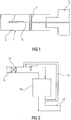
- sensor 1 shown purely schematically has a sensor element 6, which comprises a rod-shaped carrier, on the front end of a measuring electrode 2 is arranged.
- This may be, for example, an interdigital electrode.
- the conductor tracks of the measuring electrode extend in FIG. 1 to the right to a contact area (not shown).
- a plastic housing 5 forms a holder for the sensor element and has the evaluation electronics for the sensor element (not shown).
- the sensor element 6 is surrounded by a metal cap as a protective tube 3.
- the sensor element 6 extends coaxially with the metal cap, which is provided with a plurality of openings (not shown), so that the measuring electrode 2 of the sensor element 6 can come into contact with the intake air whose oxygen content is to be measured.
- the heat generated by the sensor element 6 itself is dissipated before it passes to the holder 5 for the sensor element 6 forming plastic housing.
- a plate-shaped heat dissipation element 4 is provided, which connects the sensor element 6 with the metal cap. The heat dissipation element 4 simultaneously applies to the carrier element for the metal cap.
- FIG. 2 schematically shows an internal combustion engine with a cylinder block 10, an air intake tract 11 and an exhaust tract 12. From the exhaust tract 12 extends an exhaust gas recirculation line 13 to the air intake tract 11. Further, a charge air cooler 14 in the intake manifold 11 is shown schematically.
- the in FIG. 1 shown sensor 1 is used in this embodiment for measuring the oxygen content in the intake air and is arranged in the intake manifold between the charge air cooler 14 and the cylinder block 14 of the engine downstream of the point of confluence of the exhaust gas recirculation line 13 in the intake manifold 11. At this point prevail 11 relatively low temperatures in the intake manifold, so that the holder 5 of the sensor element realized as a plastic housing can be. Overall, the holder 5 is heated neither by the sensor element 6 itself (by the heat dissipation to the metal cap) nor by the gas flow excessively.
Landscapes
- Engineering & Computer Science (AREA)
- Chemical & Material Sciences (AREA)
- General Engineering & Computer Science (AREA)
- Mechanical Engineering (AREA)
- Combustion & Propulsion (AREA)
- Analytical Chemistry (AREA)
- Health & Medical Sciences (AREA)
- Life Sciences & Earth Sciences (AREA)
- Biochemistry (AREA)
- General Health & Medical Sciences (AREA)
- General Physics & Mathematics (AREA)
- Immunology (AREA)
- Pathology (AREA)
- Physics & Mathematics (AREA)
- Electrochemistry (AREA)
- Chemical Kinetics & Catalysis (AREA)
- Molecular Biology (AREA)
- Measuring Oxygen Concentration In Cells (AREA)
- Exhaust-Gas Circulating Devices (AREA)
Description
- Die vorliegende Erfindung betrifft einen Sensor zur Erfassung des Sauerstoffgehaltes im Ansaugtrakt einer Brennkraftmaschine. Die Erfindung ist ferner auf eine einen derartigen Sauerstoffsensor aufweisende Brennkraftmaschine gerichtet.
- Bei Brennkraftmaschinen ist es in einer Reihe von Fällen gewünscht, den Sauerstoffgehalt in der Ansaugluft im Ansaugtrakt der Brennkraftmaschine zu erfassen. Dies ist beispielsweise dann der Fall, wenn die Brennkraftmaschine mit Einrichtungen zur Abgasrückführung in den Ansaugtrakt versehen ist. Hier soll über die Erfassung des Sauerstoffgehaltes die Abgasrückführungsrate ermittelt werden. Ohne Abgasrückführung beträgt der O2-Gehalt in der Ansaugluft ca. 21 % und sinkt mit zunehmendem Abgasrückführungsanteil.
- Nach dem Stand der Technik werden hierbei als Sauerstoffsensoren herkömmliche lineare Lambdasonden verwendet, wie sie im Abgasstrang der Brennkraftmaschine Verwendung finden. Da diese Lambdasonden im Abgas sehr heiß werden, besitzen sie ein teures hochtemperaturtaugliches Gehäuse. Es kommen somit beim Stand der Technik aufwändige und teure Einrichtungen zur Anwendung, um den Sauerstoffanteil in der Ansaugluft zu messen. Ein Sauerstoffsensor zum Einbau in den Ansaugtrakt ist aus der
EP0859231 A1 bekannt. - Der vorliegenden Erfindung liegt die Aufgabe zugrunde, einen Sensor zur Erfassung des Sauerstoffgehaltes im Ansaugtrakt einer Brennkraftmaschine zu schaffen, der sich durch eine besonders kostengünstige Konstruktion auszeichnet.
- Diese Aufgabe wird erfindungsgemäß gelöst durch einen Sensor zur Erfassung des Sauerstoffgehaltes im Ansaugtrakt einer Brennkraftmaschine mit einem eine Messelektrode aufweisenden Sensorelement, einer das Sensorelement umgebenden Metallkappe, einem Sensorelement und Metallkappe verbindenden Wärmeableitelement und einer als Kunststoffgehäuse ausgebildeten und die Auswerte-Elektronik für das Sensorelement aufnehmenden Halterung für das Sensorelement.
- Bei der erfindungsgemäß ausgebildeten Sensorkonstruktion wird die Wärme, die vom Sensorelement selbst erzeugt wird, über das Wärmeableitelement an die das Sensorelement umgebende Metallkappe abgeleitet, so dass auf diese Weise die Halterung für das Sensorelement nicht zu heiß wird. Diese Halterung ist folglich keiner hohen Wärmebeaufschlagung ausgesetzt, so dass sie erfindungsgemäß als Kunststoffgehäuse ausgebildet sein kann. Die Erfindung zeichnet sich ferner dadurch aus, dass in diesem Kunststoffgehäuse die Auswerteelektronik für das,Sensorelement untergebracht ist, wodurch die Konstruktion weiter vereinfacht wird. Durch die direkt am Sensor angebrachte Elektronik wird die Signalauswertung, insbesondere die Abspeicherung der entsprechenden Kennlinien erleichtert.
- Zusätzlich zu einem derartigen Sauerstoffsensor ist in vielen Fällen ein Drucksensor im Luftansaugtrakt erforderlich, um den im Luftansaugtrakt herrschenden Druck zu messen und auf Basis dieser Messung entsprechende Druckkorrekturen durchführen zu können. Beim Stand der Technik wird hierbei neben dem Sauerstoffsensor ein zusätzlicher Drucksensor mit eigenem Montageloch vorgesehen.
- In Weiterbildung der Erfindung ist der Sensor zur Erfassung des Sauerstoffgehaltes so ausgebildet, dass er einen integrierten Drucksensor aufweist. Bei dieser Ausführungsform der Erfindung findet somit eine Sensorkonstruktion Verwendung, die einen kombinierten Sauerstoffsensor und Drucksensor aufweist. Ein zusätzlicher, getrennter Drucksensor kann daher entfallen.
- Bei dieser Konstruktion haltert das Kunststoffgehäuse des Sauerstoffsensors des Weiteren das Sensorelement des Drucksensors. In Weiterbildung nimmt hierbei das Kunststoffgehäuse ferner die Auswerteelektronik für den Drucksensor auf.
- Das Sensorelement des Sauerstoffsensors umfasst insbesondere einen länglichen plattenförmigen Träger und eine darauf angeordnete Messelektrode. Das Sensorelement erstreckt sich dabei koaxial zur Metallkappe, die mit einer oder mehreren Öffnungen versehen ist, damit die Messelektrode des Sensorelementes mit der Ansaugluft in Kontakt treten kann.
- Es ist von Bedeutung, dass die vom Sensorelement selbst erzeugte Wärme abgeführt wird, bevor sie zur Halterung für das Sensorelement gelangt. Um dies zu erreichen, ist erfindungsgemäß das Wärmeableitelement vorgesehen, das das Sensorelement mit der dieses mit Abstand umgebenden Metallkappe verbindet. Speziell ist das Wärmeableitelement hierbei als das Sensorelement umgebendes und die Innenseite der Metallkappe kontaktierendes plattenförmiges Element ausgebildet. Das Wärmeableitelement bildet somit gleichzeitig ein Trägerelement für die Metallkappe.
- Die als Kunststoffgehäuse ausgebildete Halterung für das Sensorelement besteht vorzugsweise aus Epoxidharz und ist vorzugsweise durch Transfermolding hergestellt. Diese bevorzugte Ausbildung sorgt für eine sehr gute Dichtheit, die für das entsprechende Sensorkonzept mit niedrigen Strömen von Bedeutung ist. Da das Kunststoffgehäuse die Auswerte-Elektronik aufnimmt, fallen niedrige Kosten an, da Kabelverbindungen entfallen.
- Die vorliegende Erfindung bezieht sich ferner auf eine Brennkraftmaschine mit einem Luftansaugtrakt und einem darin angeordneten Ladeluftkühler. Erfindungsgemäß ist vorgesehen, dass die Brennkraftmaschine einen Sensor der vorstehend beschriebenen Art aufweist, der zwischen Ladeluftkühler und Zylinderblock der Brennkraftmaschine im Luftansaugtrakt angeordnet ist. Der erfindungsgemäß ausgebildete Sauerstoffsensor oder die erfindungsgemäß ausgebildete Kombination aus Sauerstoffsensor und Drucksensor ist damit in der vorteilhaften Position nach dem Ladeluftkühler angeordnet. An dieser Stelle sind die Temperaturen relativ niedrig, so dass die Ausgestaltung der Sensorhalterung in der Form eines Kunststoffgehäuses realisiert werden kann. Bei dieser Positionierung des Sensors wird daher die Halterung für das Sensorelement weder durch den zu messenden Gasstrom, noch durch das Sensorelement selbst (in Folge der Wärmeableitung auf die Metallklappe) übermäßig stark mit Wärme beaufschlagt.
- Die Erfindung betrifft ferner eine Brennkraftmaschine, die eine Abgasrückführleitung in den Luftansaugtrakt aufweist. Hierbei dient der Sensor (Sauerstoffsensor) zur Erfassung der Abgasrückführungsrate. Es versteht sich, dass der Sensor stromab der Mündungsstelle der Abgasrückführleitung in den Luftansaugtrakt im Luftansaugtrakt angeordnet ist.
- Die erfindungsgemäße Ausgestaltung der Halterung des Sensorelementes in der Form eines Kunststoffgehäuses ermöglicht ferner einen gerichteten Einbau des Sensors im Luftansaugtrakt. Hierdurch steigen die Chancen, Wasserschlagprobleme zu bewältigen. Im Übrigen besitzt der erfindungsgemäß ausgebildete Sensor ohnehin eine hohe Wasserschlagfestigkeit, so dass ein Einbau nach dem Ladeluftkühler unproblematisch ist.
- Die Erfindung wird nachfolgend anhand eines Ausführungsbeispiels in Verbindung mit der Zeichnung im Einzelnen erläutert. Es zeigen:
- Figur 1
- einen schematischen Längsschnitt durch einen Sensor zur Erfassung des Sauerstoffgehaltes und
- Figur 2
- ein Schemabild einer Brennkraftmaschine mit Abgasrückführung und im Ansaugtrakt angeordneten Sensor.
- Der in
Figur 1 nur rein schematisch dargestellte Sensor 1 besitzt ein Sensorelement 6, das einen stabförmigen Träger umfasst, auf dessen vorderem Ende eine Messelektrode 2 angeordnet ist. Hierbei kann es sich beispielsweise um eine Interdigitalelektrode handeln. Die Leiterbahnen der Messelektrode erstrecken sich inFigur 1 nach rechts bis in einen Kontaktbereich (nicht gezeigt). Ein Kunststoffgehäuse 5 bildet eine Halterung für das Sensorelement und weist die Auswerteelektronik für das Sensorelement auf (nicht gezeigt). - Das Sensorelement 6 ist von einer Metallkappe als Schutzrohr 3 umgeben. Das Sensorelement 6 erstreckt sich coaxial zur Metallkappe, die mit mehreren Öffnungen (nicht gezeigt) versehen ist, damit die Messelektrode 2 des Sensorelementes 6 mit der Ansaugluft in Kontakt treten kann, deren Sauerstoffgehalt gemessen werden soll. Die vom Sensorelement 6 selbst erzeugte Wärme wird abgeführt, bevor sie zum die Halterung 5 für das Sensorelement 6 bildenden Kunststoffgehäuse gelangt. Hierzu ist ein plattenförmiges Wärmeableitelement 4 vorgesehen, das das Sensorelement 6 mit der Metallkappe verbindet. Das Wärmeableitelement 4 gilt dabei gleichzeitig das Trägerelement für die Metallkappe.
-
Figur 2 zeigt schematisch eine Brennkraftmaschine mit einem Zylinderblock 10, einem Luftansaugtrakt 11 und einem Abgastrakt 12. Vom Abgastrakt 12 erstreckt sich eine Abgasrückführleitung 13 bis zum Luftansaugtrakt 11. Ferner ist schematisch ein Ladeluftkühler 14 im Ansaugtrakt 11 dargestellt. - Der in
Figur 1 dargestellte Sensor 1 dient bei dieser Ausführungsform zur Messung des Sauerstoffgehaltes in der Ansaugluft und ist hierbei im Ansaugtrakt zwischen dem Ladeluftkühler 14 und dem Zylinderblock 14 der Brennkraftmaschine stromab der Einmündungsstelle der Abgasrückführleitung 13 in den Ansaugtrakt 11 angeordnet. An dieser Stelle herrschen im Ansaugtrakt 11 relativ niedrige Temperaturen, so dass die Halterung 5 des Sensorelementes als Kunststoffgehäuse realisiert werden kann. Insgesamt wird dabei die Halterung 5 weder durch das Sensorelement 6 selbst (durch die Wärmeableitung zur Metallkappe) noch durch den Gasstrom übermäßig erhitzt.
Claims (8)
- Sensor (1) zur Erfassung des Sauerstoffgehaltes im Ansaugtrakt (11) einer Brennkraftmaschine mit einem eine Messelektrode (2) aufweisenden Sensorelement (6), einer das Sensorelement (6) umgebenden Metallkappe (3), einem Sensorelement (6) und Metallkappe (3) verbindenden Wärmeableitelement (4) und einer als Kunststoffgehäuse ausgebildeten und die Auswerteelektronik für das Sensorelement (6) aufnehmenden Halterung (5) für das Sensorelement (6).
- Sensor (1) nach Anspruch 1, dadurch gekenn- zeichnet, dass er einen integrierten Drucksensor aufweist.
- Sensor (1) nach Anspruch 2, dadurch gekennzeichnet, dass das Kunststoffgehäuse des Weiteren das Sensorelement des Drucksensors haltert.
- Sensor (1) nach Anspruch 2 oder 3, dadurch gekennzeichnet , dass das Kunststoffgehäuse ferner die Auswerteelektronik für den Drucksensor aufnimmt.
- Sensor (1) nach einem der vorangehenden Ansprüche, dadurch gekennzeichnet, dass das Sensorelement einen länglichen plattenförmigen Träger und eine darauf angeordnete Messelektrode (2) umfasst.
- Sensor (1) nach einem der vorangehenden Ansprüche, dadurch gekennzeichnet, dass das Wärmeableitelement (4) als das Sensorelement umgebendes und die Innenseite der Metallkappe (3) kontaktierendes plattenförmiges Element ausgebildet ist.
- Brennkraftmaschine mit einem Luftansaugtrakt (11) und einem darin angeordneten Ladeluftkühler (14), dad u r c h gekennzeichnet, dass sie einen Sensor (1) nach einem der Ansprüche 1 bis 6 aufweist, der zwischen Ladeluftkühler (14) und Zylinderblock (10) der Brennkraftmaschine im Luftansaugtrakt (11) angeordnet ist.
- Brennkraftmaschine nach Anspruch 7, dadurch gekennzeichnet, dass sie eine Abgasrückführleitung (13) in den Luftansaugtrakt (11) aufweist und dass der Sensor (1) zur Erfassung der Abgasrückführungsrate dient.
Applications Claiming Priority (2)
| Application Number | Priority Date | Filing Date | Title |
|---|---|---|---|
| DE201210208054 DE102012208054A1 (de) | 2012-05-14 | 2012-05-14 | Sauerstoffsensor und diesen aufweisende Brennkraftmaschine |
| PCT/EP2013/058338 WO2013171033A1 (de) | 2012-05-14 | 2013-04-23 | Sauerstoffsensor und diesen aufweisende brennkraftmaschine |
Publications (2)
| Publication Number | Publication Date |
|---|---|
| EP2850308A1 EP2850308A1 (de) | 2015-03-25 |
| EP2850308B1 true EP2850308B1 (de) | 2016-06-15 |
Family
ID=48227214
Family Applications (1)
| Application Number | Title | Priority Date | Filing Date |
|---|---|---|---|
| EP13719465.0A Not-in-force EP2850308B1 (de) | 2012-05-14 | 2013-04-23 | Sauerstoffsensor und diesen aufweisende brennkraftmaschine |
Country Status (6)
| Country | Link |
|---|---|
| US (1) | US9791405B2 (de) |
| EP (1) | EP2850308B1 (de) |
| JP (1) | JP2015516577A (de) |
| CN (1) | CN104271936B (de) |
| DE (1) | DE102012208054A1 (de) |
| WO (1) | WO2013171033A1 (de) |
Families Citing this family (6)
| Publication number | Priority date | Publication date | Assignee | Title |
|---|---|---|---|---|
| US9435251B2 (en) | 2013-08-15 | 2016-09-06 | Ford Global Technologies, Llc | Method for estimating charge air cooler condensation storage and/or release with an intake oxygen sensor |
| DE102014215237A1 (de) * | 2014-08-01 | 2016-02-04 | Continental Automotive Gmbh | Sauerstoffsensor |
| DE102014221490A1 (de) * | 2014-10-22 | 2016-04-28 | Continental Automotive Gmbh | Sauerstoffsensor |
| US9574509B2 (en) * | 2014-12-17 | 2017-02-21 | Ford Global Technologies, Llc | System and method for exhaust gas recirculation estimation with two intake oxygen sensors |
| DE102020211142B4 (de) | 2020-09-03 | 2022-08-18 | Vitesco Technologies GmbH | Gassensor für ein Fahrzeug |
| CN114324284B (zh) * | 2022-01-06 | 2024-06-11 | 浙江五相智能科技有限公司 | 一种光学溶解氧传感器 |
Citations (10)
| Publication number | Priority date | Publication date | Assignee | Title |
|---|---|---|---|---|
| US4823760A (en) | 1987-05-21 | 1989-04-25 | Mitsubishi Denki Kabushiki Kaisha | Internal combustion engine controlling apparatus |
| EP0859231A1 (de) | 1997-02-14 | 1998-08-19 | Robert Bosch Gmbh | Gasmessfühler |
| JP2001099688A (ja) | 2000-08-21 | 2001-04-13 | Hitachi Ltd | 発熱抵抗式空気流量測定装置 |
| EP1139096A2 (de) | 2000-03-29 | 2001-10-04 | Ngk Spark Plug Co., Ltd. | Gassensor und Gassensoreinheit |
| EP1213473A2 (de) | 2000-10-26 | 2002-06-12 | Filterwerk Mann + Hummel Gmbh | Ansaugsystem |
| EP1607606A1 (de) | 2004-06-15 | 2005-12-21 | C.R.F. Società Consortile per Azioni | Verfahren und Einrichtung zur Regelung der Abgasrückführrate in einer Brennkraftmaschine basierend auf der Messung der Sauerstoff-Konzentration in einem der Brennkraftmaschine zugeführten Gasgemisch |
| DE102005023259A1 (de) | 2005-05-20 | 2006-11-23 | Daimlerchrysler Ag | Abgassensor eines Kraftfahrzeugs |
| US20070044472A1 (en) | 2005-09-01 | 2007-03-01 | Guoqing Zhang | Oxygen sensor for an internal combustion engine |
| US20090200164A1 (en) | 2008-02-08 | 2009-08-13 | Ngk Spark Plug Co., Ltd. | Gas sensor |
| JP2011145269A (ja) | 2010-01-18 | 2011-07-28 | Ngk Spark Plug Co Ltd | ガスセンサ |
Family Cites Families (22)
| Publication number | Priority date | Publication date | Assignee | Title |
|---|---|---|---|---|
| DE2855012A1 (de) * | 1978-12-20 | 1980-06-26 | Bosch Gmbh Robert | Elektrochemischer messfuehler fuer die bestimmung des sauerstoffgehaltes in gasen, insbesondere in abgasen |
| JP3873390B2 (ja) * | 1996-09-04 | 2007-01-24 | 株式会社デンソー | 酸素センサー |
| JPH10176577A (ja) | 1996-12-17 | 1998-06-30 | Toyota Motor Corp | 内燃機関の制御装置 |
| JP3523022B2 (ja) | 1997-06-26 | 2004-04-26 | 株式会社日立製作所 | 発熱抵抗体式空気流量測定装置及び内燃機関の吸気系システム及び内燃機関の制御システム |
| US6266997B1 (en) * | 1999-03-25 | 2001-07-31 | Delphi Technologies, Inc. | Thermal management of a sensor |
| US6779392B2 (en) * | 2000-04-17 | 2004-08-24 | Newbow Aerospace Limited | Tire testing device incorporating a pressure sensor, temperature sensor and oxygen sensor |
| US6418779B1 (en) * | 2000-06-09 | 2002-07-16 | Ceradex Corporation | Structure of oxygen sensor |
| EP1319929A4 (de) * | 2000-07-27 | 2006-07-12 | Hitachi Ltd | Luftströmungsmesser des thermischen typs |
| DE10337840B4 (de) * | 2003-08-18 | 2013-12-05 | Robert Bosch Gmbh | Messfühler |
| DE102005062774A1 (de) * | 2005-12-28 | 2007-07-05 | Robert Bosch Gmbh | Sensoreinheit zur Bestimmung eines Messgasparameters |
| JP2008261796A (ja) * | 2007-04-13 | 2008-10-30 | Denso Corp | 温度センサ一体型圧力センサ装置 |
| US7593828B2 (en) * | 2007-08-16 | 2009-09-22 | Gm Global Technology Operations, Inc. | Method and apparatus for monitoring a variable geometry intake air compressor device |
| JP5027686B2 (ja) * | 2008-02-08 | 2012-09-19 | 日本特殊陶業株式会社 | ガスセンサ |
| JP5007263B2 (ja) * | 2008-04-02 | 2012-08-22 | 日本特殊陶業株式会社 | ガスセンサ |
| JP2011145268A (ja) * | 2010-01-18 | 2011-07-28 | Ngk Spark Plug Co Ltd | ガスセンサ |
| JP5227345B2 (ja) * | 2010-01-18 | 2013-07-03 | 日本特殊陶業株式会社 | ガスセンサ |
| JP5149945B2 (ja) * | 2010-09-03 | 2013-02-20 | 日本特殊陶業株式会社 | ガスセンサ及びその製造方法 |
| CN101949334A (zh) * | 2010-09-15 | 2011-01-19 | 同济大学 | 一种四冲程内燃机燃烧系统及使用方法 |
| DE102011003095A1 (de) | 2011-01-25 | 2012-07-26 | Ford Global Technologies, Llc | Verfahren zur Ermittlung der SauerstoffkonzentrationO2 in einer Gasströmung und Sauerstoffsensor zur Durchführung des Verfahrens |
| FR2979017B1 (fr) * | 2011-08-08 | 2013-09-20 | Electricfil Automotive | Capteur d'echappement pour un moteur a combustion interne |
| DE102011088012A1 (de) | 2011-12-08 | 2013-06-13 | Endress + Hauser Conducta Gesellschaft für Mess- und Regeltechnik mbH + Co. KG | Sensorendmodul, Sensor und Messeinrichtung |
| DE102012200062B4 (de) | 2012-01-03 | 2015-07-23 | Continental Automotive Gmbh | Brennkraftmaschine mit im Luftansaugtrakt angeordnetem Sauerstoffsensor und Sauerstoffsensor |
-
2012
- 2012-05-14 DE DE201210208054 patent/DE102012208054A1/de not_active Ceased
-
2013
- 2013-04-23 EP EP13719465.0A patent/EP2850308B1/de not_active Not-in-force
- 2013-04-23 WO PCT/EP2013/058338 patent/WO2013171033A1/de not_active Ceased
- 2013-04-23 JP JP2015511972A patent/JP2015516577A/ja active Pending
- 2013-04-23 US US14/401,017 patent/US9791405B2/en not_active Expired - Fee Related
- 2013-04-23 CN CN201380024354.3A patent/CN104271936B/zh not_active Expired - Fee Related
Patent Citations (10)
| Publication number | Priority date | Publication date | Assignee | Title |
|---|---|---|---|---|
| US4823760A (en) | 1987-05-21 | 1989-04-25 | Mitsubishi Denki Kabushiki Kaisha | Internal combustion engine controlling apparatus |
| EP0859231A1 (de) | 1997-02-14 | 1998-08-19 | Robert Bosch Gmbh | Gasmessfühler |
| EP1139096A2 (de) | 2000-03-29 | 2001-10-04 | Ngk Spark Plug Co., Ltd. | Gassensor und Gassensoreinheit |
| JP2001099688A (ja) | 2000-08-21 | 2001-04-13 | Hitachi Ltd | 発熱抵抗式空気流量測定装置 |
| EP1213473A2 (de) | 2000-10-26 | 2002-06-12 | Filterwerk Mann + Hummel Gmbh | Ansaugsystem |
| EP1607606A1 (de) | 2004-06-15 | 2005-12-21 | C.R.F. Società Consortile per Azioni | Verfahren und Einrichtung zur Regelung der Abgasrückführrate in einer Brennkraftmaschine basierend auf der Messung der Sauerstoff-Konzentration in einem der Brennkraftmaschine zugeführten Gasgemisch |
| DE102005023259A1 (de) | 2005-05-20 | 2006-11-23 | Daimlerchrysler Ag | Abgassensor eines Kraftfahrzeugs |
| US20070044472A1 (en) | 2005-09-01 | 2007-03-01 | Guoqing Zhang | Oxygen sensor for an internal combustion engine |
| US20090200164A1 (en) | 2008-02-08 | 2009-08-13 | Ngk Spark Plug Co., Ltd. | Gas sensor |
| JP2011145269A (ja) | 2010-01-18 | 2011-07-28 | Ngk Spark Plug Co Ltd | ガスセンサ |
Also Published As
| Publication number | Publication date |
|---|---|
| EP2850308A1 (de) | 2015-03-25 |
| DE102012208054A1 (de) | 2013-11-14 |
| CN104271936B (zh) | 2016-12-07 |
| JP2015516577A (ja) | 2015-06-11 |
| US20150136095A1 (en) | 2015-05-21 |
| US9791405B2 (en) | 2017-10-17 |
| CN104271936A (zh) | 2015-01-07 |
| WO2013171033A1 (de) | 2013-11-21 |
Similar Documents
| Publication | Publication Date | Title |
|---|---|---|
| EP2831555B2 (de) | Sensor zur erfassung eines drucks und einer temperatur eines fluiden mediums | |
| DE102008060033B4 (de) | Temperaturfühler für Turbolader | |
| EP2850308A1 (de) | Sauerstoffsensor und diesen aufweisende brennkraftmaschine | |
| DE112013001060B4 (de) | Thermische Luftmengenmesseinrichtung | |
| DE102011089480A1 (de) | Sensorvorrichtung zur Erfassung mindestens einer Eigenschaft eines strömenden fluiden Mediums | |
| DE102008041038A1 (de) | Gassensor | |
| DE102010030094A1 (de) | Einlasssystem für Verbrennungsmsotor | |
| DE102008029793A1 (de) | Messvorrichtung | |
| DE112016004257T5 (de) | Gassensor | |
| DE102015113606A1 (de) | Temperatursensor | |
| DE102007056544A1 (de) | Sensoranordnung zur Bestimmung eines Tankfüllstands und Verfahren zur Herstellung hierzu | |
| DE112012004149B4 (de) | Feuchtigkeitsmessvorrichtung | |
| DE112012004663T5 (de) | Feuchtigkeitserfassungsvorrichtung | |
| DE112013002992T5 (de) | Thermischer Durchflussmesser | |
| DE2809455A1 (de) | Einrichtung zur luftmengenmessung | |
| AT503662B1 (de) | Glühkerze mit integriertem drucksensor | |
| DE102004023919B4 (de) | Luftflussraten-Messvorrichtung | |
| DE102006033467B4 (de) | Druckerfassungsvorrichtung | |
| DE102008042807A1 (de) | Vorrichtung zur Bestimmung eines Parameters eines strömenden fluiden Mediums | |
| DE112013002965T5 (de) | Thermischer Durchflussmesser | |
| DE102014211771A1 (de) | Temperaturmessvorrichtung zur Erfassung einer Temperatur eines strömenden fluiden Mediums | |
| DE102009003090A1 (de) | Sensoranordnung zur Erfassung eines Drucks | |
| DE102007056545A1 (de) | Sensoranordnung zur Bestimmung eines Tankfüllstands und Tank mit Sensoranordnung | |
| DE102007000168A1 (de) | Improved structure of gas sensor ensuring enhanced mechanical durability | |
| DE102008032309B4 (de) | Sensoranordnung zur Messung des Zustands einer Flüssigkeit, insbesondere von Öl |
Legal Events
| Date | Code | Title | Description |
|---|---|---|---|
| PUAI | Public reference made under article 153(3) epc to a published international application that has entered the european phase |
Free format text: ORIGINAL CODE: 0009012 |
|
| 17P | Request for examination filed |
Effective date: 20141215 |
|
| AK | Designated contracting states |
Kind code of ref document: A1 Designated state(s): AL AT BE BG CH CY CZ DE DK EE ES FI FR GB GR HR HU IE IS IT LI LT LU LV MC MK MT NL NO PL PT RO RS SE SI SK SM TR |
|
| AX | Request for extension of the european patent |
Extension state: BA ME |
|
| DAX | Request for extension of the european patent (deleted) | ||
| GRAP | Despatch of communication of intention to grant a patent |
Free format text: ORIGINAL CODE: EPIDOSNIGR1 |
|
| RIC1 | Information provided on ipc code assigned before grant |
Ipc: F02M 35/10 20060101AFI20151028BHEP Ipc: F02M 25/07 20060101ALI20151028BHEP Ipc: G01N 27/407 20060101ALI20151028BHEP |
|
| INTG | Intention to grant announced |
Effective date: 20151203 |
|
| GRAS | Grant fee paid |
Free format text: ORIGINAL CODE: EPIDOSNIGR3 |
|
| GRAA | (expected) grant |
Free format text: ORIGINAL CODE: 0009210 |
|
| AK | Designated contracting states |
Kind code of ref document: B1 Designated state(s): AL AT BE BG CH CY CZ DE DK EE ES FI FR GB GR HR HU IE IS IT LI LT LU LV MC MK MT NL NO PL PT RO RS SE SI SK SM TR |
|
| REG | Reference to a national code |
Ref country code: CH Ref legal event code: EP Ref country code: GB Ref legal event code: FG4D Free format text: NOT ENGLISH |
|
| RIC1 | Information provided on ipc code assigned before grant |
Ipc: F02M 26/00 20160101ALI20160511BHEP Ipc: G01N 27/407 20060101ALI20160511BHEP Ipc: F02M 35/10 20060101AFI20160511BHEP |
|
| REG | Reference to a national code |
Ref country code: IE Ref legal event code: FG4D Free format text: LANGUAGE OF EP DOCUMENT: GERMAN |
|
| REG | Reference to a national code |
Ref country code: AT Ref legal event code: REF Ref document number: 806639 Country of ref document: AT Kind code of ref document: T Effective date: 20160715 |
|
| REG | Reference to a national code |
Ref country code: DE Ref legal event code: R096 Ref document number: 502013003415 Country of ref document: DE |
|
| REG | Reference to a national code |
Ref country code: LT Ref legal event code: MG4D |
|
| REG | Reference to a national code |
Ref country code: NL Ref legal event code: MP Effective date: 20160615 |
|
| PG25 | Lapsed in a contracting state [announced via postgrant information from national office to epo] |
Ref country code: LT Free format text: LAPSE BECAUSE OF FAILURE TO SUBMIT A TRANSLATION OF THE DESCRIPTION OR TO PAY THE FEE WITHIN THE PRESCRIBED TIME-LIMIT Effective date: 20160615 Ref country code: NO Free format text: LAPSE BECAUSE OF FAILURE TO SUBMIT A TRANSLATION OF THE DESCRIPTION OR TO PAY THE FEE WITHIN THE PRESCRIBED TIME-LIMIT Effective date: 20160915 Ref country code: FI Free format text: LAPSE BECAUSE OF FAILURE TO SUBMIT A TRANSLATION OF THE DESCRIPTION OR TO PAY THE FEE WITHIN THE PRESCRIBED TIME-LIMIT Effective date: 20160615 |
|
| PG25 | Lapsed in a contracting state [announced via postgrant information from national office to epo] |
Ref country code: GR Free format text: LAPSE BECAUSE OF FAILURE TO SUBMIT A TRANSLATION OF THE DESCRIPTION OR TO PAY THE FEE WITHIN THE PRESCRIBED TIME-LIMIT Effective date: 20160916 Ref country code: HR Free format text: LAPSE BECAUSE OF FAILURE TO SUBMIT A TRANSLATION OF THE DESCRIPTION OR TO PAY THE FEE WITHIN THE PRESCRIBED TIME-LIMIT Effective date: 20160615 Ref country code: RS Free format text: LAPSE BECAUSE OF FAILURE TO SUBMIT A TRANSLATION OF THE DESCRIPTION OR TO PAY THE FEE WITHIN THE PRESCRIBED TIME-LIMIT Effective date: 20160615 Ref country code: SE Free format text: LAPSE BECAUSE OF FAILURE TO SUBMIT A TRANSLATION OF THE DESCRIPTION OR TO PAY THE FEE WITHIN THE PRESCRIBED TIME-LIMIT Effective date: 20160615 Ref country code: NL Free format text: LAPSE BECAUSE OF FAILURE TO SUBMIT A TRANSLATION OF THE DESCRIPTION OR TO PAY THE FEE WITHIN THE PRESCRIBED TIME-LIMIT Effective date: 20160615 Ref country code: LV Free format text: LAPSE BECAUSE OF FAILURE TO SUBMIT A TRANSLATION OF THE DESCRIPTION OR TO PAY THE FEE WITHIN THE PRESCRIBED TIME-LIMIT Effective date: 20160615 |
|
| PG25 | Lapsed in a contracting state [announced via postgrant information from national office to epo] |
Ref country code: EE Free format text: LAPSE BECAUSE OF FAILURE TO SUBMIT A TRANSLATION OF THE DESCRIPTION OR TO PAY THE FEE WITHIN THE PRESCRIBED TIME-LIMIT Effective date: 20160615 Ref country code: RO Free format text: LAPSE BECAUSE OF FAILURE TO SUBMIT A TRANSLATION OF THE DESCRIPTION OR TO PAY THE FEE WITHIN THE PRESCRIBED TIME-LIMIT Effective date: 20160615 Ref country code: SK Free format text: LAPSE BECAUSE OF FAILURE TO SUBMIT A TRANSLATION OF THE DESCRIPTION OR TO PAY THE FEE WITHIN THE PRESCRIBED TIME-LIMIT Effective date: 20160615 Ref country code: IS Free format text: LAPSE BECAUSE OF FAILURE TO SUBMIT A TRANSLATION OF THE DESCRIPTION OR TO PAY THE FEE WITHIN THE PRESCRIBED TIME-LIMIT Effective date: 20161015 Ref country code: CZ Free format text: LAPSE BECAUSE OF FAILURE TO SUBMIT A TRANSLATION OF THE DESCRIPTION OR TO PAY THE FEE WITHIN THE PRESCRIBED TIME-LIMIT Effective date: 20160615 |
|
| PG25 | Lapsed in a contracting state [announced via postgrant information from national office to epo] |
Ref country code: PT Free format text: LAPSE BECAUSE OF FAILURE TO SUBMIT A TRANSLATION OF THE DESCRIPTION OR TO PAY THE FEE WITHIN THE PRESCRIBED TIME-LIMIT Effective date: 20161017 Ref country code: ES Free format text: LAPSE BECAUSE OF FAILURE TO SUBMIT A TRANSLATION OF THE DESCRIPTION OR TO PAY THE FEE WITHIN THE PRESCRIBED TIME-LIMIT Effective date: 20160615 Ref country code: PL Free format text: LAPSE BECAUSE OF FAILURE TO SUBMIT A TRANSLATION OF THE DESCRIPTION OR TO PAY THE FEE WITHIN THE PRESCRIBED TIME-LIMIT Effective date: 20160615 Ref country code: SM Free format text: LAPSE BECAUSE OF FAILURE TO SUBMIT A TRANSLATION OF THE DESCRIPTION OR TO PAY THE FEE WITHIN THE PRESCRIBED TIME-LIMIT Effective date: 20160615 |
|
| REG | Reference to a national code |
Ref country code: DE Ref legal event code: R026 Ref document number: 502013003415 Country of ref document: DE |
|
| PLBI | Opposition filed |
Free format text: ORIGINAL CODE: 0009260 |
|
| 26 | Opposition filed |
Opponent name: REININGER, JAN Effective date: 20170315 |
|
| REG | Reference to a national code |
Ref country code: FR Ref legal event code: PLFP Year of fee payment: 5 |
|
| PLAX | Notice of opposition and request to file observation + time limit sent |
Free format text: ORIGINAL CODE: EPIDOSNOBS2 |
|
| PG25 | Lapsed in a contracting state [announced via postgrant information from national office to epo] |
Ref country code: DK Free format text: LAPSE BECAUSE OF FAILURE TO SUBMIT A TRANSLATION OF THE DESCRIPTION OR TO PAY THE FEE WITHIN THE PRESCRIBED TIME-LIMIT Effective date: 20160615 |
|
| PLAB | Opposition data, opponent's data or that of the opponent's representative modified |
Free format text: ORIGINAL CODE: 0009299OPPO |
|
| PLBB | Reply of patent proprietor to notice(s) of opposition received |
Free format text: ORIGINAL CODE: EPIDOSNOBS3 |
|
| R26 | Opposition filed (corrected) |
Opponent name: REININGER, JAN CHRISTIAN Effective date: 20170315 |
|
| PG25 | Lapsed in a contracting state [announced via postgrant information from national office to epo] |
Ref country code: SI Free format text: LAPSE BECAUSE OF FAILURE TO SUBMIT A TRANSLATION OF THE DESCRIPTION OR TO PAY THE FEE WITHIN THE PRESCRIBED TIME-LIMIT Effective date: 20160615 |
|
| REG | Reference to a national code |
Ref country code: CH Ref legal event code: PL |
|
| GBPC | Gb: european patent ceased through non-payment of renewal fee |
Effective date: 20170423 |
|
| REG | Reference to a national code |
Ref country code: IE Ref legal event code: MM4A |
|
| PG25 | Lapsed in a contracting state [announced via postgrant information from national office to epo] |
Ref country code: MC Free format text: LAPSE BECAUSE OF FAILURE TO SUBMIT A TRANSLATION OF THE DESCRIPTION OR TO PAY THE FEE WITHIN THE PRESCRIBED TIME-LIMIT Effective date: 20160615 |
|
| PG25 | Lapsed in a contracting state [announced via postgrant information from national office to epo] |
Ref country code: LI Free format text: LAPSE BECAUSE OF NON-PAYMENT OF DUE FEES Effective date: 20170430 Ref country code: CH Free format text: LAPSE BECAUSE OF NON-PAYMENT OF DUE FEES Effective date: 20170430 Ref country code: GB Free format text: LAPSE BECAUSE OF NON-PAYMENT OF DUE FEES Effective date: 20170423 Ref country code: LU Free format text: LAPSE BECAUSE OF NON-PAYMENT OF DUE FEES Effective date: 20170423 |
|
| REG | Reference to a national code |
Ref country code: BE Ref legal event code: MM Effective date: 20170430 |
|
| REG | Reference to a national code |
Ref country code: FR Ref legal event code: PLFP Year of fee payment: 6 |
|
| PG25 | Lapsed in a contracting state [announced via postgrant information from national office to epo] |
Ref country code: IE Free format text: LAPSE BECAUSE OF NON-PAYMENT OF DUE FEES Effective date: 20170423 |
|
| PG25 | Lapsed in a contracting state [announced via postgrant information from national office to epo] |
Ref country code: BE Free format text: LAPSE BECAUSE OF NON-PAYMENT OF DUE FEES Effective date: 20170430 |
|
| PG25 | Lapsed in a contracting state [announced via postgrant information from national office to epo] |
Ref country code: MT Free format text: LAPSE BECAUSE OF FAILURE TO SUBMIT A TRANSLATION OF THE DESCRIPTION OR TO PAY THE FEE WITHIN THE PRESCRIBED TIME-LIMIT Effective date: 20160615 |
|
| PG25 | Lapsed in a contracting state [announced via postgrant information from national office to epo] |
Ref country code: AL Free format text: LAPSE BECAUSE OF FAILURE TO SUBMIT A TRANSLATION OF THE DESCRIPTION OR TO PAY THE FEE WITHIN THE PRESCRIBED TIME-LIMIT Effective date: 20160615 |
|
| REG | Reference to a national code |
Ref country code: DE Ref legal event code: R100 Ref document number: 502013003415 Country of ref document: DE |
|
| PLCK | Communication despatched that opposition was rejected |
Free format text: ORIGINAL CODE: EPIDOSNREJ1 |
|
| PLBN | Opposition rejected |
Free format text: ORIGINAL CODE: 0009273 |
|
| STAA | Information on the status of an ep patent application or granted ep patent |
Free format text: STATUS: OPPOSITION REJECTED |
|
| 27O | Opposition rejected |
Effective date: 20181127 |
|
| REG | Reference to a national code |
Ref country code: AT Ref legal event code: MM01 Ref document number: 806639 Country of ref document: AT Kind code of ref document: T Effective date: 20180423 |
|
| PG25 | Lapsed in a contracting state [announced via postgrant information from national office to epo] |
Ref country code: HU Free format text: LAPSE BECAUSE OF FAILURE TO SUBMIT A TRANSLATION OF THE DESCRIPTION OR TO PAY THE FEE WITHIN THE PRESCRIBED TIME-LIMIT; INVALID AB INITIO Effective date: 20130423 |
|
| PG25 | Lapsed in a contracting state [announced via postgrant information from national office to epo] |
Ref country code: BG Free format text: LAPSE BECAUSE OF FAILURE TO SUBMIT A TRANSLATION OF THE DESCRIPTION OR TO PAY THE FEE WITHIN THE PRESCRIBED TIME-LIMIT Effective date: 20160615 |
|
| PG25 | Lapsed in a contracting state [announced via postgrant information from national office to epo] |
Ref country code: AT Free format text: LAPSE BECAUSE OF NON-PAYMENT OF DUE FEES Effective date: 20180423 Ref country code: CY Free format text: LAPSE BECAUSE OF FAILURE TO SUBMIT A TRANSLATION OF THE DESCRIPTION OR TO PAY THE FEE WITHIN THE PRESCRIBED TIME-LIMIT Effective date: 20160615 |
|
| PG25 | Lapsed in a contracting state [announced via postgrant information from national office to epo] |
Ref country code: MK Free format text: LAPSE BECAUSE OF FAILURE TO SUBMIT A TRANSLATION OF THE DESCRIPTION OR TO PAY THE FEE WITHIN THE PRESCRIBED TIME-LIMIT Effective date: 20160615 |
|
| PG25 | Lapsed in a contracting state [announced via postgrant information from national office to epo] |
Ref country code: TR Free format text: LAPSE BECAUSE OF FAILURE TO SUBMIT A TRANSLATION OF THE DESCRIPTION OR TO PAY THE FEE WITHIN THE PRESCRIBED TIME-LIMIT Effective date: 20160615 |
|
| REG | Reference to a national code |
Ref country code: DE Ref legal event code: R081 Ref document number: 502013003415 Country of ref document: DE Owner name: VITESCO TECHNOLOGIES GMBH, DE Free format text: FORMER OWNER: CONTINENTAL AUTOMOTIVE GMBH, 30165 HANNOVER, DE |
|
| PGFP | Annual fee paid to national office [announced via postgrant information from national office to epo] |
Ref country code: FR Payment date: 20200420 Year of fee payment: 8 |
|
| PGFP | Annual fee paid to national office [announced via postgrant information from national office to epo] |
Ref country code: IT Payment date: 20200428 Year of fee payment: 8 |
|
| REG | Reference to a national code |
Ref country code: DE Ref legal event code: R081 Ref document number: 502013003415 Country of ref document: DE Owner name: VITESCO TECHNOLOGIES GMBH, DE Free format text: FORMER OWNER: VITESCO TECHNOLOGIES GMBH, 30165 HANNOVER, DE |
|
| PG25 | Lapsed in a contracting state [announced via postgrant information from national office to epo] |
Ref country code: FR Free format text: LAPSE BECAUSE OF NON-PAYMENT OF DUE FEES Effective date: 20210430 |
|
| REG | Reference to a national code |
Ref country code: DE Ref legal event code: R084 Ref document number: 502013003415 Country of ref document: DE |
|
| PG25 | Lapsed in a contracting state [announced via postgrant information from national office to epo] |
Ref country code: IT Free format text: LAPSE BECAUSE OF NON-PAYMENT OF DUE FEES Effective date: 20200423 |
|
| P01 | Opt-out of the competence of the unified patent court (upc) registered |
Effective date: 20230530 |
|
| PGFP | Annual fee paid to national office [announced via postgrant information from national office to epo] |
Ref country code: DE Payment date: 20230430 Year of fee payment: 11 |
|
| REG | Reference to a national code |
Ref country code: DE Ref legal event code: R119 Ref document number: 502013003415 Country of ref document: DE |
|
| PG25 | Lapsed in a contracting state [announced via postgrant information from national office to epo] |
Ref country code: DE Free format text: LAPSE BECAUSE OF NON-PAYMENT OF DUE FEES Effective date: 20241105 |
|
| PG25 | Lapsed in a contracting state [announced via postgrant information from national office to epo] |
Ref country code: DE Free format text: LAPSE BECAUSE OF NON-PAYMENT OF DUE FEES Effective date: 20241105 |
|
| PG25 | Lapsed in a contracting state [announced via postgrant information from national office to epo] |
Ref country code: IT Free format text: LAPSE BECAUSE OF NON-PAYMENT OF DUE FEES Effective date: 20210423 |