EP2849002A2 - Bilderzeugungsvorrichtung, Verfahren zur Einstellung der Bilderzeugung und Speichermedium zur Speicherung von Bilddaten zur Einstellung der Bilderzeugung - Google Patents
Bilderzeugungsvorrichtung, Verfahren zur Einstellung der Bilderzeugung und Speichermedium zur Speicherung von Bilddaten zur Einstellung der Bilderzeugung Download PDFInfo
- Publication number
- EP2849002A2 EP2849002A2 EP20140180906 EP14180906A EP2849002A2 EP 2849002 A2 EP2849002 A2 EP 2849002A2 EP 20140180906 EP20140180906 EP 20140180906 EP 14180906 A EP14180906 A EP 14180906A EP 2849002 A2 EP2849002 A2 EP 2849002A2
- Authority
- EP
- European Patent Office
- Prior art keywords
- image
- recording medium
- sheet
- cross
- hair
- Prior art date
- Legal status (The legal status is an assumption and is not a legal conclusion. Google has not performed a legal analysis and makes no representation as to the accuracy of the status listed.)
- Granted
Links
- 230000015572 biosynthetic process Effects 0.000 title claims abstract description 86
- 238000000034 method Methods 0.000 title claims description 27
- 238000003708 edge detection Methods 0.000 claims abstract description 49
- 238000012937 correction Methods 0.000 description 46
- 230000008569 process Effects 0.000 description 17
- 239000011521 glass Substances 0.000 description 13
- 230000000052 comparative effect Effects 0.000 description 11
- 238000010586 diagram Methods 0.000 description 10
- 238000003384 imaging method Methods 0.000 description 9
- 238000004364 calculation method Methods 0.000 description 8
- 238000003825 pressing Methods 0.000 description 8
- 230000007246 mechanism Effects 0.000 description 6
- 238000012546 transfer Methods 0.000 description 6
- 238000011161 development Methods 0.000 description 5
- 238000000926 separation method Methods 0.000 description 5
- 230000015654 memory Effects 0.000 description 4
- 210000000078 claw Anatomy 0.000 description 3
- 238000001514 detection method Methods 0.000 description 3
- 230000003287 optical effect Effects 0.000 description 3
- 230000006835 compression Effects 0.000 description 2
- 238000007906 compression Methods 0.000 description 2
- 230000006870 function Effects 0.000 description 2
- 238000005513 bias potential Methods 0.000 description 1
- 230000008859 change Effects 0.000 description 1
- 239000003086 colorant Substances 0.000 description 1
- 239000000470 constituent Substances 0.000 description 1
- 229920001973 fluoroelastomer Polymers 0.000 description 1
- 238000003702 image correction Methods 0.000 description 1
- 238000003754 machining Methods 0.000 description 1
- 239000000463 material Substances 0.000 description 1
- 239000002985 plastic film Substances 0.000 description 1
- 238000012545 processing Methods 0.000 description 1
- 229920002379 silicone rubber Polymers 0.000 description 1
- 239000007787 solid Substances 0.000 description 1
- 230000007306 turnover Effects 0.000 description 1
- 230000003936 working memory Effects 0.000 description 1
Images







Classifications
-
- H—ELECTRICITY
- H04—ELECTRIC COMMUNICATION TECHNIQUE
- H04N—PICTORIAL COMMUNICATION, e.g. TELEVISION
- H04N1/00—Scanning, transmission or reproduction of documents or the like, e.g. facsimile transmission; Details thereof
- H04N1/40—Picture signal circuits
- H04N1/409—Edge or detail enhancement; Noise or error suppression
- H04N1/4092—Edge or detail enhancement
-
- G—PHYSICS
- G03—PHOTOGRAPHY; CINEMATOGRAPHY; ANALOGOUS TECHNIQUES USING WAVES OTHER THAN OPTICAL WAVES; ELECTROGRAPHY; HOLOGRAPHY
- G03G—ELECTROGRAPHY; ELECTROPHOTOGRAPHY; MAGNETOGRAPHY
- G03G15/00—Apparatus for electrographic processes using a charge pattern
- G03G15/50—Machine control of apparatus for electrographic processes using a charge pattern, e.g. regulating differents parts of the machine, multimode copiers, microprocessor control
- G03G15/5062—Machine control of apparatus for electrographic processes using a charge pattern, e.g. regulating differents parts of the machine, multimode copiers, microprocessor control by measuring the characteristics of an image on the copy material
-
- H—ELECTRICITY
- H04—ELECTRIC COMMUNICATION TECHNIQUE
- H04N—PICTORIAL COMMUNICATION, e.g. TELEVISION
- H04N1/00—Scanning, transmission or reproduction of documents or the like, e.g. facsimile transmission; Details thereof
- H04N1/00681—Detecting the presence, position or size of a sheet or correcting its position before scanning
- H04N1/00684—Object of the detection
- H04N1/00726—Other properties of the sheet, e.g. curvature or reflectivity
-
- H—ELECTRICITY
- H04—ELECTRIC COMMUNICATION TECHNIQUE
- H04N—PICTORIAL COMMUNICATION, e.g. TELEVISION
- H04N1/00—Scanning, transmission or reproduction of documents or the like, e.g. facsimile transmission; Details thereof
- H04N1/00681—Detecting the presence, position or size of a sheet or correcting its position before scanning
- H04N1/00729—Detection means
- H04N1/00734—Optical detectors
-
- H—ELECTRICITY
- H04—ELECTRIC COMMUNICATION TECHNIQUE
- H04N—PICTORIAL COMMUNICATION, e.g. TELEVISION
- H04N1/00—Scanning, transmission or reproduction of documents or the like, e.g. facsimile transmission; Details thereof
- H04N1/00681—Detecting the presence, position or size of a sheet or correcting its position before scanning
- H04N1/00729—Detection means
- H04N1/00734—Optical detectors
- H04N1/00737—Optical detectors using the scanning elements as detectors
-
- H—ELECTRICITY
- H04—ELECTRIC COMMUNICATION TECHNIQUE
- H04N—PICTORIAL COMMUNICATION, e.g. TELEVISION
- H04N1/00—Scanning, transmission or reproduction of documents or the like, e.g. facsimile transmission; Details thereof
- H04N1/00681—Detecting the presence, position or size of a sheet or correcting its position before scanning
- H04N1/00742—Detection methods
- H04N1/00748—Detecting edges, e.g. of a stationary sheet
-
- H—ELECTRICITY
- H04—ELECTRIC COMMUNICATION TECHNIQUE
- H04N—PICTORIAL COMMUNICATION, e.g. TELEVISION
- H04N1/00—Scanning, transmission or reproduction of documents or the like, e.g. facsimile transmission; Details thereof
- H04N1/00681—Detecting the presence, position or size of a sheet or correcting its position before scanning
- H04N1/00742—Detection methods
- H04N1/00761—Detection methods using reference marks, e.g. on sheet, sheet holder or guide
-
- H—ELECTRICITY
- H04—ELECTRIC COMMUNICATION TECHNIQUE
- H04N—PICTORIAL COMMUNICATION, e.g. TELEVISION
- H04N1/00—Scanning, transmission or reproduction of documents or the like, e.g. facsimile transmission; Details thereof
- H04N1/00681—Detecting the presence, position or size of a sheet or correcting its position before scanning
- H04N1/00763—Action taken as a result of detection
- H04N1/00774—Adjusting or controlling
-
- G—PHYSICS
- G03—PHOTOGRAPHY; CINEMATOGRAPHY; ANALOGOUS TECHNIQUES USING WAVES OTHER THAN OPTICAL WAVES; ELECTROGRAPHY; HOLOGRAPHY
- G03G—ELECTROGRAPHY; ELECTROPHOTOGRAPHY; MAGNETOGRAPHY
- G03G15/00—Apparatus for electrographic processes using a charge pattern
- G03G15/65—Apparatus which relate to the handling of copy material
- G03G15/6582—Special processing for irreversibly adding or changing the sheet copy material characteristics or its appearance, e.g. stamping, annotation printing, punching
-
- G—PHYSICS
- G03—PHOTOGRAPHY; CINEMATOGRAPHY; ANALOGOUS TECHNIQUES USING WAVES OTHER THAN OPTICAL WAVES; ELECTROGRAPHY; HOLOGRAPHY
- G03G—ELECTROGRAPHY; ELECTROPHOTOGRAPHY; MAGNETOGRAPHY
- G03G2215/00—Apparatus for electrophotographic processes
- G03G2215/00362—Apparatus for electrophotographic processes relating to the copy medium handling
- G03G2215/00535—Stable handling of copy medium
- G03G2215/00556—Control of copy medium feeding
- G03G2215/00569—Calibration, test runs, test prints
-
- H—ELECTRICITY
- H04—ELECTRIC COMMUNICATION TECHNIQUE
- H04N—PICTORIAL COMMUNICATION, e.g. TELEVISION
- H04N2201/00—Indexing scheme relating to scanning, transmission or reproduction of documents or the like, and to details thereof
- H04N2201/04—Scanning arrangements
- H04N2201/047—Detection, control or error compensation of scanning velocity or position
- H04N2201/04701—Detection of scanning velocity or position
- H04N2201/04715—Detection of scanning velocity or position by detecting marks or the like, e.g. slits
- H04N2201/04717—Detection of scanning velocity or position by detecting marks or the like, e.g. slits on the scanned sheet, e.g. a reference sheet
Definitions
- Embodiments of the present invention generally relate to an image forming apparatus, a method of adjusting the image formation, and a storage medium storing image data for adjustment of image formation.
- Such image forming apparatuses usually form an image on a recording medium according to image data.
- a charger uniformly charges a surface of a photoconductor serving as an image carrier.
- An optical writer irradiates the surface of the photoconductor thus charged with a light beam to form an electrostatic latent image on the surface of the photoconductor according to the image data.
- a development device supplies toner to the electrostatic latent image thus formed to render the electrostatic latent image visible as a toner image.
- the toner image is then transferred, directly or indirectly via an intermediate transfer belt onto a recording medium.
- a fixing device applies heat and pressure to the recording medium carrying the toner image to fix the toner image onto the recording medium.
- the image is formed on the recording medium.
- JP-H08-115011-A discloses an image forming apparatus that adjusts image formation such as a writing timing of a writer by forming a skew correction image as an image for adjustment of image formation on a recording medium and detecting, e.g., image skew with respect to the recording medium.
- the image forming apparatus reads image data for adjustment of image formation (i.e., skew correction image data) from a storage thereof, and forms the skew correction image on the recording medium according to the image data.
- the image data includes cross-hairs that are formed in the respective corners of the recording medium. According to the image data, the cross-hair is formed on, e.g., an end of the recording medium as a skew correction image.
- the image forming apparatus scans the recording medium carrying the cross-hairs with a scanner and calculates, e.g., a distance between an end of the recording medium and a cross-hair closest to the end according to the scan data. According to the distance thus calculated, the image forming apparatus detects, e.g., an amount of image skew with respect to the recording medium, and adjusts image formation such as a writing timing of the writer, thereby correcting an image that is formed on the recording medium.
- JP-2006-011285-A discloses a method of correcting an image forming position that includes scanning a cross-hair formed on a recording medium. Specifically, first, a user or operator places the recording medium on a contact glass of a scanner by separating from an end of the contact glass the two corners on one end of the recording medium in a longitudinal direction thereof, in which cross-hairs are formed, respectively. Then, the user or operator places an auxiliary member on the contact glass such that the auxiliary member is partly visible beyond the two corners of the recording medium. It is to be noted that the auxiliary member is longer than a short side of the recording medium and provides a contrast between the auxiliary member and a surface of the recording medium on which the cross-hairs are formed. The scanner scans (1) the auxiliary member partly visible beyond the two corners of the recording medium, (2) at least the two corners of the recording medium, and (3) the cross-hairs formed in the two corners, respectively.
- the two corners of the recording medium can be accurately detected from the scan data because of the contrast between the auxiliary member and the recording medium.
- a distance between an end of the recording medium and a cross-hair closest to the end is calculated according to the scan data. According to the distance thus calculated, an image forming device is controlled and thus an image forming position is corrected.
- the image forming apparatus identifies the size of the recording medium according to paper size data stored in the storage thereof, and presumes an end position of the recording medium placed at a predetermined position of the scanner from the size thus identified.
- the distance between the end of the recording medium and the closest cross-hair is calculated according to the end position of the recording medium thus presumed and the cross-hair scanned. Accordingly, if the recording medium carrying the cross-hairs is skewed from the predetermined position, the amount of skew of the recording medium is detected as image skew.
- the image forming position after the image formation is adjusted may be worse than that before the image formation is adjusted.
- JP-2006-011285-A the scanner scans the corners of the recording medium and the cross-hairs formed therein. Accordingly, even if the recording medium is skewed from the predetermined position, the distances between the corner edges of the recording medium and the closest cross-hairs can be accurately detected. As a result, image skew can be accurately detected, preventing the above-described problem in that the image forming position after the image formation is adjusted may be worse than that before the image formation is adjusted.
- JP-2006-011285-A uses the auxiliary member that is longer than the short side of the recording medium carrying the cross-hairs and has a higher density than the recording medium. Such an auxiliary member may not be found easily.
- To prepare the auxiliary member the user or operator must do additional work such as looking for such an auxiliary member or operating the image forming apparatus to output a recording medium as an auxiliary member. If the operator adjusts the image formation, the operator has to bring the auxiliary member to the user.
- an improved non-transitory computer-readable storage medium storing image data for adjustment of image formation.
- the image data includes a cross-hair formed in a corner of a recording medium, and a corner edge detection mark formed to detect a folded corner edge of the recording medium from read data obtained when the corner of the recording medium including an area where the cross-hair is formed on one side is folded to an opposite side to the one side of the recording medium and an image reader reads the opposite side.
- an improved image forming apparatus that includes an image forming device, an image reader, a non-transitory computer-readable storage medium, and an adjuster.
- the image forming device forms an image on a recording medium.
- the image reader reads an image from a recording medium.
- the non-transitory computer-readable storage medium stores image data for adjustment of image formation.
- the image data includes a cross-hair formed in a corner of a recording medium.
- the adjuster reads the image data from the non-transitory computer-readable storage medium, forms an image for adjustment of image formation on a recording medium with the image forming device, reads the image for adjustment of image formation from the recording medium with the image reader, and adjusts image formation according to read data provided by the image reader.
- the adjuster When the corner of the recording medium including an area where the cross-hair is formed on one side is folded to an opposite side to the one side of the recording medium, the adjuster reads the opposite side with the image reader, detects the cross-hair and a corner edge of the recording medium from read data provided by the image reader, calculates a distance between the cross-hair and the corner edge of the recording medium, and adjusts the image formation according to the distance between the cross-hair and the corner edge of the recording medium.
- an improved method of adjusting image formation of an image forming apparatus that includes forming a cross-hair in a corner of a recording medium, folding the corner of the recording medium including an area where the cross-hair is formed on one side, to an opposite side to the one side of the recording medium, reading the opposite side with an image reader, detecting the cross-hair and a corner edge of the recording medium according to read data provided by the image reader to calculate a distance between the cross-hair and the corner edge of the recording medium, and adjusting image formation of the image forming apparatus according to the distance between the cross-hair and the corner edge of the recording medium.
- adjustment of image formation can be simplified while securing the advantages of the method disclosed by JP-2006-011285-A .
- FIG. 1 is a schematic view of the image forming apparatus 400.
- the image forming apparatus 400 includes an automatic document feeder (ADF) 500 to automatically convey an original loaded thereon, a scanner 300 serving as an image reader to read the original, and a printer 100 to form a toner image.
- ADF automatic document feeder
- the printer 100 includes a writer 102, an imaging unit 125, and a transfer and fixing unit 130.
- the writer 102 includes optical components such as a polygon mirror 104 and a reflection mirror 106.
- the imaging unit 125 includes, e.g., photoconductive drums 115 and development devices 120.
- the transfer and fixing unit 130 includes, e.g., a conveyor belt 116 and a fixing device 117.
- the writer 102 further includes a laser output unit 103, which is illustrated in FIG. 11 , to emit a light beam L.
- the light beam L emitted from the laser output unit 103 is condensed by a cylindrical lens and deflected by the polygon mirror 104 toward the reflection mirror 106.
- the light beam L is directed to each of the photoconductive drums 115K, 115Y, 115C, and 115M (hereinafter collectively referred to as photoconductive drums 115) via a corresponding imaging lens to form an electrostatic latent image thereon.
- the electrostatic latent images thus formed are conveyed to the development devices 120K, 120Y, 120C, and 120M (hereinafter referred to as development devices 120) as the photoconductive drums 115 rotate, respectively.
- the development devices 120 develop the electrostatic latent images with developers of the respective colors to form visible toner images on the photoconductive drums 115.
- the photoconductive drums 115 rotate while carrying the toner images, and thus convey the toner images to the transfer and fixing unit 130.
- the transfer and fixing unit 130 includes trays 108, 109 and 110, feed units 111, 112, and 113, and a vertical conveyance unit 114 in addition to the conveyor belt 116 and the fixing device 117.
- Each of the trays 108 through 110 accommodates sheets P such as sheets of fine paper or plastic sheets.
- the feed units 111 through 113 feed the sheets P from the respective trays 108 through 110 one by one to the vertical conveyance unit 114.
- the vertical conveyance unit 114 conveys a sheet P fed by one of the feed units 111 through 113 to a position where the sheet P contacts the closest photoconductive drum, in this case, the photoconductive drum 115M.
- the sheet P thus conveyed is then electrostatically attached to the conveyor belt 116.
- the toner images are transferred onto the sheet P from the respective photoconductive drums 115 at a transfer bias potential to form a color toner image thereon.
- the sheet P carrying the color toner image is then conveyed to the fixing device 117.
- the fixing device 117 includes, e.g., a fixing member such as a fixing roller including silicon rubber or fluororubber.
- the color toner image is fixed onto the sheet P under heat and pressure to form a color image thereon.
- the sheet P may be slightly constricted from heat.
- the sheet P is then conveyed to a discharge unit 118, which discharges the sheet P onto a discharge tray 119.
- the discharge unit 118 includes a separation claw 121 to direct the sheet P to a duplex unit 122.
- the discharge unit 118 does not discharge the sheet P onto the discharge tray 119, but directs the sheet P to the duplex unit 122 with the separation claw 121 in a tilted position.
- the sheet P conveyed to the duplex unit 122 is fed to the vertical conveyance unit 114 to consequently carry another image on the other side.
- the sheet P carrying images on both sides reaches the discharge unit 118, which discharges the sheet P onto the discharge tray 119 with the separation claw 121 in a flat position.
- the ADF 500 is disposed atop the scanner 300 and includes a platen 501, a separation and feed roller 502, an original conveyor belt 503, and an original discharge tray 504.
- the separation and feed roller 502 feeds the originals one by one from the platen 501 to the original conveyor belt 503.
- the original conveyor belt 503 guides the originals onto a contact glass 309 where each of the originals temporally stops.
- the scanner 300 scans image data of the original temporally stopping on the contact glass 309. Thereafter, the original conveyor belt 503 resumes conveyance of the original to discharge the original onto the original discharge tray 504.
- the scanner 300 includes a first carrier 303, a light source 301 and a mirror 302 provided on the first carrier 303, a second carrier 306, mirrors 304 and 305 provided on the second carrier 306, a lens 307, and a charge coupled device (CCD) 308.
- the light source 301 is lighted when the ADF 500 conveys the original onto the contact glass 309 or when a user places an original on the contact glass 309 and directs the image forming apparatus 400 to start copying via an operation panel 48, which is illustrated in FIG. 2 .
- the first carrier 303 and the second carrier 306 are moved along a guide rail.
- the light source 301 emits light to the original positioned on the contact glass 309. Reflection light from the original is guided to the CCD 308 via the mirror 302, the mirrors 304 and 305, and the lens 307.
- the CCD 308 receives the reflection light and reads the image data of the original.
- the image data is converted from analog to digital data by an analog-to-digital (A/D) converted.
- A/D analog-to-digital
- the writer 102 forms the electrostatic latent images on the respective photoconductive drums 115 according to the image data obtained from the scanner 300.
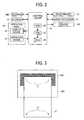
- FIG. 2 is a block diagram of a control system of the image forming apparatus 400 described above.
- the image forming apparatus 400 includes a control circuit 15.
- the control circuit 15 is connected to, e.g., the scanner 300, a storage 12, an image memory 13, an image processor 21, the printer 100, an operation device 14 and a display device 18.
- the operation device 14 and the display device 18 constitute the operation panel 48.
- the image forming apparatus is set to an image forming mode or a correction mode.
- the operation device 14 is also used to set image forming conditions.
- the display device 18 displays the image forming conditions selected through the operation device 14.
- the control circuit 15 includes a read-only memory (ROM) 24, a central processing unit (CPU) 25, and a random access memory (RAM) 26.
- the ROM 24 accommodates system program data for controlling the entire image forming apparatus 400.
- the RAM 26 is used as a working memory.
- the RAM 26 temporally stores, e.g., scan data (or read data) of an image for adjustment and a control command.
- the CPU 25 reads the system program data from the ROM 24 to initialize a system, thereby controlling the entire image forming apparatus 400 according to operation data from the operation device 14.
- the storage 12 is a non-volatile memory such as an electrically erasable programmable read-only memory (EEPROM) to store a program for executing the correction mode.
- the CPU 25 reads and executes the program.
- the storage 12 also stores image data for adjustment of image formation, which is read by the CPU 25 to form an image for adjustment on, e.g., a sheet P, as described later.
- the printer 100 can form an image on the sheet P larger than a maximum size of sheet P that the scanner 300 can scan.
- a maximum paper size that the printer can handle is larger than a maximum scan size.
- the maximum scan size is A3 and the maximum paper size is A3 wide.
- FIG. 3 is a diagram illustrating a comparative example of scanning an image for adjustment.
- the image forming apparatus 400 may form an image skewed on a sheet P' if the sheet P' is skewed and conveyed.
- an operator operates the operation panel 48 to select the correction mode upon installing the image forming apparatus 400 to adjust at least one of a series of image forming processes including conveyance of the sheet P' to the imaging unit 125. If the operator sets the correction mode, image data for adjustment of image formation is read from the storage 12 and an image for adjustment is formed on the sheet P' according to the image data for adjustment of image formation. As illustrated in FIG. 3 , the image for adjustment includes cross-hairs 1' formed in four corners of the sheet P', respectively.
- the image forming apparatus 400 displays, with the display device 18 of the operation panel 48, an instruction to place the sheet P' on the scanner 300 when the sheet P' is outputted. According to the instruction provided through the display device 18, the operator places the sheet P' carrying the image for adjustment on the scanner 300 to scan the sheet P' carrying the image for adjustment.
- the image forming apparatus 400 measures a positional relation between a corner of the sheet P' and the corresponding cross-hair 1' according to the scan data to calculate a difference between the measured position and a target position. According to the difference thus calculated, the image forming apparatus 400 executes image adjustment such as a skew correction described later.
- an image for adjustment is preferably formed on a maximum size of sheet P' that the printer 100 can handle, because a longer distance between one end to the other of the sheet P' increases a difference between a cross-hair formed on one end of the sheet P' and a cross-hair formed on the other end of the sheet P'.
- the image for adjustment is formed on the maximum size of sheet P' and the operator places the maximum size of sheet P' on the contact glass 309 of the scanner 300 in a normal manner, that is, with its width direction (horizontal direction) along a main scanning direction, the sheet P' partly protrudes from the contact glass 309.
- the sheet P' partly protrudes from the contact glass 309.
- the sheet P' is rotated at 90 degrees from a position in which the sheet P' is placed in the normal manner. In other words, the sheet P' is placed with its width direction along a sub-scanning direction.
- the scanner 300 scans the sheet P' over which an auxiliary member 1001 is placed.
- the auxiliary member 1001 is longer than the sheet P' in the width direction thereof and has a higher density than the sheet P'.
- auxiliary member such as the auxiliary member 1001.
- Such users may have to prepare the maximum size of sheet P' and the auxiliary member to adjust image formation.
- operators may have to bring the maximum size of sheet P' and the auxiliary member to the users to adjust image formation.
- adjustment of image formation is complicated.
- an original pressing board facing the contact glass 309 of the scanner 300 is white, which is the same color as the sheet P'. Accordingly, even if the sheet P' carrying the image for adjustment is smaller than the maximum scan size, detecting corners of the sheet P' from the scan data accompanies use of the auxiliary member 1001.
- the scanner 300 scans the cross-hairs 1' formed on the sheet P' placed at a predetermined position of the scanner 300. An end position of the sheet P' placed at the predetermined position is presumed from paper size data. Positions of the end of the sheet P' and the corresponding cross-hair 1' are calculated according to the end position of the sheet P' thus presumed and the position of the cross-hair 1' thus scanned. However, if the sheet P' carrying the cross-hairs 1' is skewed from the predetermined position, the amount of skew of the sheet P' is detected as image skew. Accordingly, adjustment of image formation may not effectively correct an image position.
- cross-hairs 1' formed on both ends of the sheet P' in a longitudinal direction thereof, that is, a vertical direction are detected to detect and correct a vertical magnification error of an image in addition to image skew. If the sheet P' carrying the cross-hairs 1' is larger than the maximum scan size, firstly, cross-hairs 1' formed on one end of the sheet P' in the longitudinal direction thereof and the corresponding corners are scanned, as illustrated in FIG. 3 . Then, the sheet P' is rotated at 180 degrees so that cross-hairs 1' formed on the other end of the sheet P' in the longitudinal direction thereof and the corresponding corners are scanned. Thus, detecting the four corners of the sheet P' and the cross-hairs 1' formed therein requires performing the scanning operation twice, thereby complicating adjustment of image formation.
- the present embodiment simplifies such complicated adjustment of image formation by use of an image for adjustment.
- FIGS. 4A through 4C a description is given of the image for adjustment according to the present embodiment.
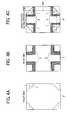
- FIG. 4A is a plan view of a front side of the sheet P illustrating an image for adjustment according to the present embodiment.
- FIG. 4B is a plan view of a back side of the sheet P illustrating another image for adjustment according to the present embodiment.
- FIG. 4C is a plan view of the sheet P illustrating a side to be scanned by the scanner 300.
- the sheet P has four cross-hairs 1 and four folding lines 3 in four corners on the front side, respectively.
- the sheet P has four corner edge detection marks 2 on the back side to detect corner edges of the sheet P.
- each of the four corner edge detection marks 2 is formed to detect ends in each of the four corners of the sheet P in the longitudinal and width directions thereof, respectively.
- the corner edges of the sheet P come over the corner edge detection marks 2 when the four corner are folded backward along the folding lines 3 such that areas including the respective cross-hairs 1 are within a scan area, that is, within the contact glass 309 of the scanner 300 indicated by a chain line.
- the corner edge detection marks 2 partly remain visible beyond the respective corner edges of the sheet P.
- the corner edge detection marks 2 may have any shapes, patterns and density as long as the ends of the sheet P in the width direction thereof and those in the longitudinal direction thereof can be detected.
- the corner edge detection marks 2 may be solid images or halftone images.
- the corner edge detection marks 2 since a higher contrast between the sheet P and the corner edge detection marks 2 contributes to more accurate detection of ends of the sheet P, the corner edge detection marks 2 preferably have a certain level of density to ensure accurate detection of the edges of the sheet P.
- the folding lines 3 are formed to help an operator or user to fold the corners of the sheet P.
- the images for adjustment may omit the folding lines 3.
- the four corners of the sheet P and the cross-hairs 1 are located inward from their previous positions before the sheet P is folded. Accordingly, when the folded sheet P is set on the scanner 300, the four corner edges of the sheet P and the cross-hairs 1 are within the scan area of the scanner 300 even if the sheet P is larger than the maximum scan size.
- the corner edge detection marks 2 are not completely covered by the four corners of the sheet P folded, and thus partly remain visible, thereby generating a contrast between the corner edges of the sheet P and the corner edge detection marks 2. Accordingly, the cross-hairs 1 formed in the four corners of the sheet P and the corner edges of the sheet P can be scanned at once. In addition, the corner edges of the sheet P can be accurately detected from the scan data without using the auxiliary member 1001 illustrated in FIG. 3 . Thus, adjustment of image formation can be simplified.
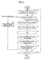
- FIG. 5 is a flowchart of the control process of adjustment of image formation.
- the control circuit 15 confirms the operating mode of the image forming apparatus (S1).
- the image forming mode is the default mode. If the image forming mode is set (No in S2), the control circuit 15 executes a normal image forming process (S10). On the other hand, if the operator or user sets the correction mode through the operation panel 48 (Yes in S2), the control circuit 15 executes adjustment of image formation. It is to be noted that the correction mode is selected through a menu screen of the display device 18 and thus set.
- the control circuit 15 controls the operation panel 48 to display a screen with the display device 18 that instructs the operator or user to input a paper size of the sheet P on which the images for adjustment are formed, a tray to use, or both.
- the operator or user operates the operation device 14 of the operation panel 48 to input the paper size (e.g., A3), the tray that accommodates the sheet P, or both.
- the control circuit 15 Upon receiving paper size data, tray data, or both from the operation device 14, the control circuit 15 stores the paper size data, the tray data, or both in, e.g., the RAM 26. Then, the control circuit 15 outputs the images for adjustment according to the paper size data, the tray data, or both (S3).
- the images for adjustment may be outputted onto a predetermined size of paper only, or only a predetermined tray may be used to feed a sheet on which the images for adjustment are outputted, or both.
- the maximum paper size e.g., A3 wide
- a bypass tray may be designated.
- the display device 18 displays an instruction to set a predetermined size of sheet on the predetermined tray. According to the instruction, the operator or user sets the predetermined size of sheet on the predetermined tray and presses a start button on the operation device 14 to output the images for adjustment.
- the control circuit 15 reads the image data for adjustment of image formation from the storage 12 to transmit the image data for adjustment of image formation and the paper size data stored in the RAM 26 to the image processor 21.
- the control circuit 21 generates output data for controlling ON/OFF of exposure of the writer 102 according to the image data for adjustment of image formation and the paper size data.
- the writer 102 is controlled according to the output data thus generated, and forms a latent image to be an image for adjustment illustrated in FIGS. 4A or 4B on, e.g., the photoconductive drum 115K.
- the sheet P carries the images for adjustment illustrated in FIGS. 4A and 4B on both sides and outputted from the image forming apparatus 400.
- the control circuit 15 displays, with the display device 18 of the operation panel 48, an instruction to fold the four corners of the sheet P along the folding lines 3 and set the folded sheet P on the scanner 300 (S4).
- the operator or user folds the four corners of the sheet P carrying the images for adjustment, and sets the folded sheet P on the scanner 300.
- the operator or user operates the display device 18 of the operation panel 48 to scan the folded sheet P carrying the images for adjustment (S5).
- the control circuit 15 After the scanner 300 scans the folded sheet P carrying the images for adjustment, the control circuit 15 detects the cross-hairs 1 and the corner edges of the sheet P, that is, ends in each corner of the sheet P in the longitudinal direction thereof (sub-scanning direction) and in the width direction thereof (main scanning direction), respectively, according to scan data (S6). Then, the control circuit 15 calculates positions (coordinates) of the cross-hairs 1 (S7). If the control circuit 15 fails to detect the corner edges of the sheet P, the cross-hairs 1, or both from the scan data, the operator or user may have set the sheet P without folding it and scanned the unfolded sheet P.
- control circuit 15 generates a warning sound or displays, with the display device 18 of the operation panel 48, the instruction to fold the four corners of the sheet P along the folding lines 3 and scan the folded sheet P, or both, thereby directing the operator or user to do so again.
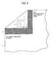
- FIG. 6 is an enlarged view of the sheet P of FIG. 4C illustrating a corner including an area where the image for adjustment is formed.
- FIG. 7 is a diagram illustrating a one-dimensional signal in areas surrounded by broken lines in FIG. 6 .
- the scan data includes the cross-hairs 1 formed in the four corners of the sheet P, respectively, the corner edges of the sheet P, that is, the ends in each corner in the main scanning and the sub-scanning directions, respectively, and the corner edge detection marks 2 visible in black outside the corner edges.
- Each of areas X and Y of the scan data surrounded by broken lines in FIG. 6 is equalized in an edge direction of the sheet P to obtain the one-dimensional signal illustrated in FIG. 7 .
- the one-dimensional signal has a predetermined threshold. Intersections of the threshold and the one-dimensional signal are detected as an end P1, and edge positions P2 and P3 of a straight line of the cross-hair 1, respectively.
- the area X illustrated in FIG. 6 is analyzed to detect the cross-hair 1 and the end of the sheet P in the width direction thereof.
- the area Y illustrated in FIG. 6 is analyzed to detect the cross-hair 1 and the end of the sheet P in the longitudinal direction thereof.
- a distance between the end P1 and a center of the cross-hair 1 is calculated by
- coordinates (x1, y1) of an interception of the straight lines of the cross-hair 1 is calculated when the origin is the corner of the sheet P, that is, when the position of P1 is zero in both areas X and Y.
- Coordinates of the other three cross-hairs 1 are calculated in this manner. Then, the control circuit 15 executes adjustment of image formation according to the coordinates of the cross-hairs 1 thus calculated (S8). According to the present embodiment, the control circuit 15 corrects, e.g., image skew and an image position as the adjustment of image formation.
- FIG. 8 is a partial view of the sheet P for describing calculation of an amount of image skew.
- the amount of image skew is calculated using, among the coordinates of the cross-hairs 1 formed in the four corners of the sheet P, the coordinates of an cross-hair formed in one corner on a leading end of the sheet P in the width direction thereof (herein called an cross-hair 1L), and coordinates of an cross-hair formed in the other corner on the leading end of the sheet P (herein called an cross-hair 1R).
- the coordinates of the cross-hair 1L are (x1, y1), where x1 is a distance aL and y1 is a distance bL, when the origin is the corner closest to the cross-hair 1L.
- the coordinates of the cross-hair 1R are (x1, y1), where x1 is a distance aR and y1 is a distance bR, when the origin is the corner closest to the cross-hair 1R.
- the skew is corrected according to the amount of image skew calculated according to the coordinates of the cross-hairs 1L and 1R. Specifically, the image skew is corrected by changing an angle of a skew correction board 81 with respect to a direction in which the sheet P is conveyed. It is to be noted that the skew correction board 81 is provided near a pair of registration rollers 80 illustrated in FIG. 9 .
- FIG. 9 is a diagram illustrating the correction of a sheet skew using the skew correction board 81.
- an upper roller 80a of the pair of registration rollers 80 is separated from a lower roller 80b of the pair of registration rollers 80.
- the leading end of the sheet P fed from one of the trays 108 through 110 hits against the skew correction board 81 and stops moving there. Accordingly, a skew of the sheet P is corrected.
- the upper roller 80a of the pair of registration rollers 80 descends to sandwich the sheet P between the upper roller 80a and the lower roller 80b of the pair of registration rollers 80.
- the skew correction board 81 is moved to allow the pair of registration rollers 80 to send the sheet P to the imaging unit 125. Accordingly, the sheet P of which the skew is corrected is conveyed straight to the imaging unit 125.
- the image skew can be corrected by changing the angle of the skew correction board 81 with respect to the direction in which the sheet P is conveyed.
- the storage 12 stores a table correlating amounts of skew and amounts of adjustment of the skew correction board 81.
- the control circuit 15 reads the table from the storage 12 after the amount of skew is calculated. Then, the control circuit 15 determines an amount of adjustment of the skew correction board 81 according to the table, based on the calculated amount of skew, and displays, with the display device 18 of the operation panel 48, the amount of adjustment of the skew correction board 81 thus determined.
- the operator or user moves one end of the skew correction board 81 in a width direction thereof to change the angle of the skew correction board 81 with respect to the direction in which the sheet P is conveyed. Accordingly, the sheet P is conveyed straight to the imaging unit 125 and an image can be formed on the sheet P without a skew.
- an adjustment mechanism may be provided to automatically adjust the angle of the skew correction board 81 with respect to the direction in which the sheet P is conveyed according to the amount of adjustment of the skew correction board 81.
- FIG. 10 is a partial view of the sheet P illustrating a measured position and a target position.
- Correcting the image position starts with calculating a difference between the measured position and the target position.
- the origin of these coordinates is the corner of the sheet P closest to the cross-hair 1L.
- the storage 12 preliminary stores the coordinates (x0, y0) of the target position.
- the cross-hair used to correct an image position can be any one of the cross-hairs 1 formed in the four corners of the sheet P.
- a cross-hair located at a position where the writer 102 starts writing is used to correct an image position.
- the cross-hair 1L is used to correct an image position, which is located on the leading end and on the left side of the sheet P and at the position where the writer 102 starts writing.
- An image position is corrected by correcting writing control of the writer 102 according to the calculated difference. Specifically, the image position is corrected by adjusting a combination of count values of main scanning and sub-scanning counters and timing signals for writing image data at a desired position on, e.g., the photoconductive drum 115K as an electrostatic latent image.
- FIG. 11 is a schematic view of the writer 102 with one of the photoconductive drums 115 incorporated in the image forming apparatus 400.
- the writer 102 includes a synchronization sensor 105 to determine a writing timing in the main scanning direction.
- a light beam scanned by the polygon mirror 104 firstly enters the synchronization sensor 105.
- the synchronization sensor 105 Upon detecting the light beam, the synchronization sensor 105 outputs a synchronization signal with respect to the main scanning direction (hereinafter simply referred to as main scanning sync signal).
- main scanning sync signal a synchronization signal with respect to the main scanning direction
- the laser output unit 103 emits laser light according to the image data.
- the sheet sensor 82 when a sheet sensor 82 provided near the pair of registration rollers 80 illustrated in FIG. 9 detects the leading end of the sheet P, the sheet sensor 82 outputs a synchronization signal with respect to the sub-scanning direction (hereinafter simply referred to as sub-scanning sync signal) to determine a writing timing in the sub-scanning direction.
- sub-scanning sync signal a synchronization signal with respect to the sub-scanning direction
- the laser output unit 103 emits laser light according to the image data.
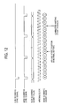
- FIG. 12 is a diagram illustrating the correction of writing control.
- a writing start position is two counts from the sub-scanning sync signal and two counts from the main scanning sync signal. If it is detected from the scan data of the image for adjustment that the image for adjustment is shifted from the target position by one scanned line in the sub-scanning direction and by one dot in the main scanning direction, for example, the writing start position is corrected to be three counts from the sub-scanning sync signal and three counts from the main scanning sync signal. Accordingly, the image position is corrected and an image is formed at a target position.
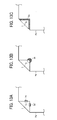
- FIGS. 13A through 13C illustrates variations in the shape of the corner edge detection marks 2.
- FIG. 13A is a partial view of a sheet Pa illustrating corner edge detection marks 2a and 2a' as a first variation.
- FIG. 13B is a partial view of a sheet Pb illustrating a corner edge detection mark 2b as a second variation.
- FIG. 13C is a partial view of a sheet Pc illustrating a corner edge detection mark 2c as a third variation.
- FIG. 13A is a partial view of a sheet Pa illustrating corner edge detection marks 2a and 2a' as a first variation.
- FIG. 13B is a partial view of a sheet Pb illustrating a corner edge detection mark 2b as a second variation.
- FIG. 13C is a partial view of a sheet Pc illustrating a corner edge detection mark 2c as a third variation.
- FIG. 13A is a partial view of a sheet Pa illustrating corner edge detection marks 2a and 2a' as a first variation
- the corner edge detection mark 2a is partly visible beyond an end of the sheet Pa in a longitudinal direction thereof.
- the corner edge detection mark 2a' is partly visible beyond an end of the sheet Pa in a width direction thereof.
- the corner edge detection mark 2b is partly visible beyond a corner of a sheet Pb.
- the corner edge detection mark 2c is formed along ends of the sheet Pc on a front side, on which the cross-hair 1 is formed.
- the cross-hairs 1 may be formed in four corners of a sheet for adjustment having front and back sides colored differently.
- the four corners of the sheet for adjustment are folded backward including areas where the cross-hairs 1 are formed, thereby generating a contrast between the folded corners and the back side of the sheet for adjustment. Accordingly, ends of the sheet for adjustment and the cross-hairs 1 can be detected from scan data of the back side of the sheet for adjustment of which the four corners are folded backward.
- FIGS. 14A through 17 a description is given of a first variation of the above-described embodiment.
- an image formed on a front side of a sheet slightly shrinks during the fixing process, compared to that after transferred on the sheet, because the sheet slightly shrinks by being heated during the fixing process.
- the image formed on the back side of the sheet is consequently larger than the image formed on the front side of the sheet.
- FIG. 14A is a plan view of a sheet P10 carrying an image for adjustment on each side according to the first variation.
- FIG. 14B is a plan view of the sheet P10 illustrating a side to be scanned by the scanner 300.
- the image for adjustment includes the cross-hairs 1, the corner edge detection marks 2, and the folding lines 3.
- the four corners of the sheet P10 are folded backward so that the scanner 300 scans positions of the cross-hairs 1 formed on a front side of the sheet P10 with respect to the corresponding corners of the sheet P10.
- the corner edge detection marks 1 formed on a back side of the sheet P10 are partly visible beyond the corner edges of the sheet P10. Accordingly, the corner edges of the sheet P10 and the cross-hairs 1 formed on the front side of the sheet P10 can be accurately detected.
- the four corners of the sheet P10 is folded frontward so that the scanner 300 scans positions of the cross-hairs 1 formed on the back side of the sheet P10 with respect to the corresponding corners of the sheet P10.
- the corner edge detection marks 1 formed on the front side of the sheet P10 are partly visible beyond the corner edges of the sheet P10. Accordingly, the corner edges of the sheet P10 and the cross-hairs 1 formed on the back side of the sheet P10 can be accurately detected.
- the cross-hairs 1 formed in the four corners on each side of the sheet P10 can be detected by performing the scanning operation twice.
- the cross-hairs 1' can be detected by performing the scanning operation four times.
- the image data for adjustment of image formation may further include different kinds of identification mark images, such as identification marks 4a and 4b, so that the scanner 300 distinguishes between front and back sides of a sheet P11.
- FIG. 15A is a plan view of the front side of the sheet P11 carrying the image for adjustment of FIG. 14A that further includes one kind of identification marks 4a.
- FIG. 15B is a plan view of the back side of the sheet P11 carrying the image for adjustment of FIG. 14A that further includes another kind of identification marks 4b.
- the identification marks 4a are triangles whereas the identification marks 4b are circles.
- identification marks 4a and 4b allows the scanner 300 to distinguish between the front and back sides of the sheet P11.
- identification marks may be formed on a single side of the sheet P11 so that the scanner 300 distinguishes between the front and back sides of the sheet P11.
- FIG. 16 is a flowchart of the control process of adjustment of image formation according to the first variation.
- the control circuit 15 confirms the operating mode (S 11). As in the embodiment described above, the default mode is the image forming mode. If the image forming mode is set (No in S12), the control circuit 15 executes a normal image forming process (S21). On the other hand, if an operator or user sets a correction mode through the operation device 14 of the operation panel 48 (Yes in S12) and inputs the paper size data, the tray data, or both, the control circuit 15 outputs the images for adjustment illustrated in FIGS. 14A and 14B (S13).
- the control circuit 15 displays, with the display device 18 of the operation panel 48, an instruction to fold backward the four corners of the sheet P10 along the folding lines 3 and set the folded sheet P10 on the scanner 300 (S14).
- the operator or user folds backward the four corners of the sheet P10 in which the cross-hairs 1 are formed, and sets the folded sheet P10 on the scanner 300 to scan the back side of the folded sheet P10(S15).
- the control circuit 15 displays, with the display device 18 of the operation panel 48, an instruction to fold opposite the four corners of the sheet P10 along the folding lines 3, turn over the sheet P10, and set the sheet P10 on the scanner 300 (S16).
- the operator or user folds opposite the four corners of the sheet P10 in which the cross-hairs 1 are formed, turns over the sheet P10, and sets the sheet P10 on the scanner 300 to scan the front side of the folded sheet P10 (S17).
- the control circuit 15 After the scanner 300 scans the sheet P10 twice, the control circuit 15 detects the cross-hairs 1 and the corner edges of the sheet P10, that is, ends of the sheet P10 in longitudinal and width directions thereof according to scan data obtained in the first scanning operation and scan data obtained in the second scanning operation. Then, the control circuit 15 calculates positions (coordinates) of the cross-hairs 1 formed on the front and back sides of the sheet P10, respectively (S18). It is to be noted that the cross-hairs 1 and the corner edges of the sheet P10, that is, the ends of the sheet P10 in the longitudinal and width directions thereof are detected as in the embodiment described above. Similarly, the positions (coordinates) of the cross-hairs 1 with respect to their respective closest corners of the sheet P10 as the origins are calculated as in the embodiment described above.
- control circuit 15 executes adjustment of image formation according to the coordinates of the cross-hairs 1 thus calculated (S19).
- the control circuit 15 corrects a magnification of the image formed on the back side of the sheet P10 as the adjustment of image formation.
- image skew, an image position, or both may be corrected using the coordinates of the cross-hairs 1 formed on the front or back side of the sheet P10.
- Correcting a magnification of an image starts with calculating a degree of magnification of an image formed on the back side of the sheet P10 relative to an image formed on the front side of the sheet P, based on the positions of the cross-hairs 1 formed on the front and back sides of the sheet P, respectively.
- the degree of magnification can be calculated based on a positional difference between the cross-hairs 1 formed on the front side of the sheet P and those formed on the back side of the sheet P.
- FIG. 17 is an enlarged view of the sheet P10 illustrating a leading end thereof for describing calculation of the degree of magnification in the width direction thereof.
- a toner image formed on a front side of a sheet shrinks slightly when it is fixed onto the sheet because the sheet shrinks slightly during the fixing operation. In other words, the image formed on the front side of the sheet is smaller than an image formed on the back side of the sheet.
- the control circuit 15 After calculating the degree of magnification MW in the width direction of the sheet P10 and the degree of magnification ML in the longitudinal direction thereof, the control circuit 15 displays calculated data with the display device 18 of the operation panel 48. According to the calculated data displayed by the display device 18, the operator or user operates the operation device 14 to input vertical and horizontal magnifications of the back side of the sheet P10. For example, the operator or user inputs magnification of 0.98 of the back side of the sheet P10 relative to the front side thereof. Instead of inputting a magnification as described above, the image forming apparatus 400 may automatically correct the degree of magnification.
- the degree of magnification is corrected by correcting a writing start position for forming an image on the back side of the sheet P10 while removing dots according to a predetermined algorithm from image data for forming an image on the back side of the sheet P10 (hereinafter referred to as back side image data).
- the writing start timing from the main scanning sync signal is corrected according to (BaL - FaL)
- the writing start timing from the sub-scanning sync signal is corrected according to (BbL - FbL).
- the number of dots to be removed along the main scanning direction from the back side image data is calculated according to the horizontal magnification inputted by the operator or user. The calculated number of dots are removed from the back side image data according to the predetermined algorithm.
- the horizontal magnification of a back side image that is, image to be formed on the back side of the sheet P10 is slightly compressed.
- the number of images to be removed along the main scanning direction from the back side image data is calculated according to the vertical magnification inputted. For example, if the number of images thus calculated corresponds to two scans, two scans of images are removed along the main scanning direction from the back side image data. Accordingly, the vertical magnification of the back side image is slightly compressed.
- the writing timing of the back side image is corrected taking into account the corrected amount.
- the magnification error between the front and back sides of the sheet P10 is corrected by slightly compressing the back side image.
- the magnification error between the front and back sides of the sheet P10 may be corrected by slightly enlarging a front side image, that is, image to be formed on the front side of the sheet P10.
- magnification errors between the measured position and the target position may be calculated and corrected for each of the front and back side images.
- MW A - aL + A - aR / H ⁇ 0
- ML B - bL + B - bL ⁇ / L ⁇ 0
- H0 and L0 is a distance between the target positions
- bL' is a position of a cross-hair formed in a left corner on a trailing end of the sheet P from the left corner of the trailing end of the sheet P in the longitudinal direction thereof.
- FIGS. 18A through 26 a description is given of a second variation of the above-described embodiment.
- FIG. 18A is a plan view of a front side of a sheet P20 illustrating an image for adjustment according to the second variation.
- FIG. 18B is a plan view of a back side of the sheet P20 illustrating another image for adjustment according to the second variation.
- FIG. 18C is a partially enlarged view of the sheet P20 illustrating a side to be scanned by the scanner 300.
- the images for adjustment of the second variation include a frame 5 and an edge detection mark 6.
- the frame 5 is formed on the front side of the sheet P20 in addition to the cross-hairs 1 formed in four corners of the sheet P20.
- an edge detection mark 6 is formed on the back side of the sheet P20 to detect edges of the sheet P20, in addition to the corner edge detection marks 2.
- each of the four corners of the sheet P20 that is scanned is like a corner illustrated in FIG. 18C .
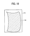
- the edge detection mark 6 is partly visible beyond the edges of the sheet P20 folded backward, thereby generating a contrast between the edge detection mark 6 and the edges of the sheet P20. Accordingly, a positional relation between the frame 5 and the edges of the sheet P20 can be acknowledged from scan data obtained from the scanner 300, thereby detecting an image deformation such as an image 1100 deformed on a sheet P21 illustrated in FIG. 19 .
- FIG. 20 is a flowchart of the control process of adjustment of image formation according to the second variation.
- the control circuit 15 confirms the operating mode (S31). As in the embodiment described above, the default mode is the image forming mode.. If the image forming mode is set (No in S32), the control circuit 15 executes a normal image forming process (S41). On the other hand, if an operator or user sets a correction mode through the operation device 14 of the operation panel 48 (Yes in S32) and inputs the paper size data, the tray data, or both, the control circuit 15 outputs the images for adjustment illustrated in FIGS. 18A and 18B (S33).
- the control circuit 15 displays, with the display device 18 of the operation panel 48, an instruction to fold the four corners of the sheet P20 along the folding lines 3, then fold all the edges (i.e., sides) of the sheet P20, and set the folded sheet P20 on the scanner 300 (S34).
- the operator or user folds the sheet P20 carrying the images for adjustment, and sets the folded sheet P20 on the scanner 300 to scan the folded sheet P20 carrying the images for adjustment (S35).
- the control circuit 15 After the scanner 300 scans the folded sheet P20 carrying the images for adjustment, the control circuit 15 detects the cross-hairs 1, the frame 5, the edges of the sheet P20, and the corner edges of the sheet P20, that is, ends in each corner of the sheet P20 in the longitudinal and width directions thereof, respectively (S36). Then, the control circuit 15 calculates positions (coordinates) of the cross-hairs 1 from their respective origins, that is, closest corners (S37). The control circuit 15 also calculates the position of the frame 5 from the edges of the sheet P20 (S38).
- control circuit 15 executes an image correction (S39).
- the control circuit 15 corrects an image position and image skew according to the coordinates of the cross-hairs 1 thus calculated.
- control circuit 15 corrects an image deformation according to the position of the frame 5. The image position and the image skew are corrected as in the above-described embodiment.
- FIG. 21A is a plan view of a back side of a sheet P22 for describing distances between the frame 5 and the ends of the sheet P22, and distances between the cross-hairs 1 and the ends of the sheet P22 when an image is deformed on the sheet P22 as illustrated in FIG. 19 .
- FIG. 21B is a plan view of a front side of the sheet P22 for describing distances between the frame 5 and the ends of the sheet P22, and distances between the cross-hairs 1 and the ends of the sheet P22 when the image is deformed on the sheet P22 as illustrated in FIG. 19 .
- a distance K2 is longer than distances K1 and K3.
- the distance K1 is a distance between a left end of the sheet P22 and the cross-hair 1L formed in a top left corner of the sheet P22.
- the distance K2 is a distance between the left end of the sheet P22 and a center of the frame in a vertical direction thereof.
- the distance K3 is a distance between the left end of the sheet P22 and an cross-hair 1L' formed in a bottom left corner of the sheet P22.
- a distance K5 is shorter than distances K4 and K6.
- the distance K4 is a distance between a right end of the sheet P22 and the cross-hair 1R formed in a top right corner of the sheet P22.
- the distance K5 is a distance between the right end of the sheet P22 and a center of the frame in the vertical direction thereof.
- the distance K6 is a distance between the right end of the sheet P22 and a cross-hair 1R' formed in a bottom right corner of the sheet P22.
- an image deformation in the main scanning direction can be calculated that may not be acknowledged only by forming the cross-hairs 1L, 1R, 1L' and 1R' in the four corners of the sheet P22, respectively.
- the image deformation may not be like the image 1100 illustrated in FIG. 19 in which the center of the image 1100 is recessed most.
- the image may be recessed most in an upper portion thereof or the image may be deformed as a wave.
- the distances between the frame 5 and the ends of the sheet P20 can be detected. Accordingly, any types of image deformation can be accurately detected.
- Image deformation in the main scanning direction is corrected by adjusting the writing start timing in the main scanning direction at each position in the sub-scanning direction, that is, the longitudinal direction of the sheet P2, according to the distance between the frame 5 and an end of the sheet P20 at each position in the sub-scanning direction.
- a distance K8 is longer than distances K7 and K9.
- the distance K7 is a distance between a top end of the sheet P22 and the cross-hair 1L.
- the distance K8 is a distance between the top end of the sheet P22 and a center of the frame in a horizontal direction thereof.
- the distance K9 is a distance between the top end the sheet P22 and the cross-hair 1R.
- a distance K11 is shorter than distances K10 and K12.
- the distance K10 is a distance between a bottom end of the sheet P22 and the cross-hair IL'.
- the distance K11 is a distance between the bottom end of the sheet P22 and a center of the frame in the horizontal direction thereof.
- the distance K12 is a distance between the bottom end of the sheet P22 and the cross-hair 1R'.
- the control circuit 15 detects an image deformation in the sub-scanning direction as illustrated in FIG. 19 . If an image is skewed, an amount of image skew is deducted upon calculation of the distances K8, K9, K11, and K12. Accordingly, an image deformation in the sub-scanning direction can be calculated that may not be detected only by forming the cross-hairs 1L, 1R, 1L' and 1R' in the four corners of the sheet P22, respectively.
- deformation or curvature of an image in the sub-scanning direction results from curvature of a scanned line of laser light directed onto a photoconductor from a writer due to slight deformation of optical components such as a lens or mirror of the writer by, e.g., machining errors.
- deformation correction mechanism 107 a mechanism for correcting deformation of an image in the sub-scanning direction (hereinafter simply referred to as deformation correction mechanism 107).
- FIG. 22 is a schematic view of the deformation correction mechanism 107 incorporated in the writer 102.
- a holder 52 holds the mirror 106 from behind, that is, a non-specular side of the mirror 106.
- a protrusion 52a serving as a supporter is provided at each end of the holder 52 in a longitudinal direction thereof and protrudes toward the reflection mirror 106.
- the protrusions 52a contact a back side, that is, the non-specular side of the mirror 106.
- a flat spring 54 serving as a first bender is attached to the holder 52 inward from each protrusion 52a in the longitudinal direction thereof.
- Each flat spring 54 presses the reflection mirror 106 in a direction indicated by arrow A, from a specular side to the back side of the reflection mirror 106. Accordingly, the reflection mirror 106 is bent at the center in the longitudinal direction thereof from the specular side to the back side thereof. In other words, the reflection mirror 106 is held by the holder 52 while being bent by the flat spring 54.
- a pressing device 64 serving as a second bender is disposed behind the holder 52 to press, via the holder 52, the center of the reflection mirror 106 in the longitudinal direction thereof in a direction indicated by arrow B, which is opposite a direction in which the holder 52 is bent.
- FIG. 23 is a schematic perspective view of the reflection mirror 106 bent by the flat spring 54.
- the reflection mirror 106 In an initial state, that is, when the pressing device 64 does not press the reflection mirror 106, the reflection mirror 106 is bent in directions indicated by arrow R, from the specular side to the back side thereof.
- the pressing device 64 slightly presses the reflection mirror 106 in the initial state in the direction indicated by arrow B, the reflection mirror 106 is bent in the direction opposite the direction in which the reflection mirror 106 is bent by the flat spring 54. Accordingly, as illustrated in FIG. 24 , an amount of curvature of the reflection mirror 106 is reduced.
- the pressing device 64 further presses the reflection mirror 106, as illustrated in FIG.
- the reflection mirror 106 is bent in a direction opposite the direction in which the reflection mirror 106 is bent in the initial state.
- the reflection mirror 106 can be bent either to the back side or the specular side thereof. Accordingly, as illustrated in FIG. 26 , curvature of a main scanned line Lb indicated by a solid line and a main scanned line Lc indicated by a chain line can be corrected.
- a main scanned line that is bent can be corrected to be a straight main scanned line La indicated by a broken line in FIG. 26 . Accordingly, image deformation in the sub-scanning direction is corrected.
- a non-transitory computer-readable storage medium (e.g., storage 12) stores image data for adjustment of image formation.
- the image data is read from the non-transitory computer-readable storage medium to form an image for adjustment on a recording medium (e.g., sheet P) when image formation is adjusted in the image forming apparatus, more specifically, when at least one of a series of image forming processes including conveyance of the recording medium to an imaging device (e.g., imaging unit 125) is adjusted.
- a recording medium e.g., sheet P
- an imaging device e.g., imaging unit 125
- the image data includes a cross-hair (e.g., cross-hair 1) formed in a corner of the recording medium and a corner edge detection mark (e.g., corner edge detection mark 2) formed to detect a folded corner edge of the recording medium from read data obtained when the corner of the recording medium including an area where the cross-hair is formed on one side is folded to an opposite side to the one side of the recording medium and an image reader (e.g., scanner 300) reads the opposite side.
- the image forming apparatus forms the cross-hair and the corner edge detection mark on the recording medium.
- the corner edge detection mark allows the folded corner edge of the recording medium to be detected from the read data.
- an operator or user simply folds the corner of the recording medium including the area where the cross-hair is formed and sets the folded recording medium on the image reader.
- image adjustment is simplified compared to a comparative example of scanning the cross-hair and the corner edge of the recording medium using an auxiliary member, which is looked for or outputted by the image forming apparatus and set on the image reader such that the auxiliary member is partly visible beyond the recording medium set on the image reader.
- the operator adjusts image formation, the operator is free from carrying the auxiliary member every time the operator adjusts image formation.
- the image reader can read the cross-hair and the corner edge of the recording medium. Accordingly, the distance between the cross-hair and the corner edge of the recording medium can be accurately calculated, and advantages of the above-described comparative example can be also secured.
- the corner edge detection mark generates a contrast between the folded corner edge and the opposite side of the recording medium.
- the corner edge of the recording medium can be accurately detected.
- the cross-hair is formed in each corner of the recording medium, and the corner edge detection mark is formed on the opposite side of the recording medium at a position where, when the corner of the recording medium is folded such that the cross-hair and the corner edge are positioned in an image read range of the image reader, the folded corner edge of the recording medium is positioned.
- each corner of the recording medium and the cross-hair formed therein can be detected in a scanning operation.
- the image adjustment is simplified compared to the comparative example of scanning the four corners of the recording medium and the cross-hairs formed in the four corners of the recording medium by performing the scanning operation twice.
- the cross-hair and the corner edge detection mark are formed on a front side and a back side of the recording medium.
- a degree of magnification of an image formed on a back side of the recording medium can be detected with respect to an image formed on a front side of the recording medium.
- the image data of the fourth aspect further includes an identification mark (e.g., identification mark 4a or 4b) to distinguish between the front side and the back side of the recording medium.
- an identification mark e.g., identification mark 4a or 4b
- the front and back sides of the recording medium can be distinguished, even though the recording medium carries the cross-hair and corner edge detection mark on each side.
- the image data further includes a frame (e.g., frame 5), and an edge detection mark (e.g., edge detection mark 6) formed to detect a folded edge of the recording medium from read data provided obtained when the edge of the recording medium including an area where the frame is formed on the one side is folded to the opposite side and the image reader reads the opposite side.
- a frame e.g., frame 5
- an edge detection mark e.g., edge detection mark 6
- the image data further includes a frame (e.g., frame 5), and an edge detection mark (e.g., edge detection mark 6) formed to detect a folded edge of the recording medium from read data provided obtained when the edge of the recording medium including an area where the frame is formed on the one side is folded to the opposite side and the image reader reads the opposite side.
- image deformation can be detected as in the second variation described above.
- an image forming apparatus (e.g., image forming apparatus 400) includes an image forming device (e.g., printer 100) to form an image on a recording medium, an image reader (e.g., scanner 300) to read an image from a recording medium (e.g., sheet P), a non-transitory computer-readable storage medium (e.g., storage 12) to store image data for adjustment of image formation.
- the image data includes a cross-hair (e.g., cross-hair 1) formed in a corner of a recording medium.
- the image forming apparatus further includes an adjuster (e.g., control circuit 15) to read the image data from the non-transitory computer-readable storage medium, to form an image for adjustment of image formation on a recording medium with the image forming device, to read the image for adjustment of image formation formed from the recording medium with the image reader, and to adjust image formation according to read data provided by the image reader.
- an adjuster e.g., control circuit 15
- the adjuster When the corner of the recording medium including an area where the cross-hair is formed on one side is folded to an opposite side to the one side of the recording medium, the adjuster reads the opposite side with the image reader, detects the cross-hair and a corner edge of the recording medium from read data provided by the image reader, calculates a distance between the cross-hair and the corner edge of the recording medium, and adjusts the image formation according to the distance between the cross-hair and the corner edge of the recording medium.
- a recording medium having front and back sides differently colored is used to form the cross-hair thereon.
- the adjustment of the image forming apparatus is simplified compared to an image forming apparatus employing the comparative example that requires a recording medium to form the cross-hair thereon and the auxiliary member.
- the cross-hair and the corner edge of the recording medium are detected from the read data. Accordingly, the distance between the cross-hair and the corner edge of the recording medium can be accurately detected, and the image formation can be accurately adjusted.
- the image data is the image data of any one of the first to sixth aspects.
- the image forming apparatus outputs the recording medium carrying the cross-hair and the corner edge detection mark, use of a recording medium having front and back sides colored differently can be omitted, thereby simplifying the adjustment of image formation.
- the adjuster detects a difference between a position of an image and a target image forming position according to the distance between the cross-hair and the corner edge of the recording medium, and adjusts the image formation such that the image is formed at the target image forming position.
- an image can be formed at a target position.
- the cross-hair is formed in each corner on one end of the recording medium in a longitudinal direction of the recording medium.
- the adjuster detects an amount of image skew with respect to the recording medium according to a distance between the one end of the recording medium in the longitudinal direction and the cross-hair formed on one end of the recording medium in a lateral direction of the recording medium, and a distance between the one end of the recording medium in the longitudinal direction and the cross-hair formed on another end of the recording medium in the lateral direction, and adjusts the image formation to correct the image skew.
- an image can be formed on a recording medium without being skewed.
- the image data is the image data of the fourth or fifth aspect.
- the adjuster detects a difference between a position of an image formed on the front side of the recording medium and a position of an image formed on the back side of the recording medium according to a front side read data provided by the image reader when the image reader reads the back side of the recording medium after the corner of the recording medium including an area where the cross-hair is formed on the front side of the recording medium is folded to the back side of the recording medium, and according to a back side read data provided by the image reader when the image reader reads the front side of the recording medium after the corner of the recording medium including an area where the cross-hair is formed on the back side of the recording medium is folded to the front side of the recording medium.
- the adjuster adjusts the image formation such that the position of the image formed on the front side of the recording medium and the position of the image formed on the back side of the recording medium match each other.
- the image can be outputted on each side of the recording medium while the position of the image formed on the front side of the recording medium and the position of the image formed on the back side of the recording medium match each other.
- the image data is the image data of the sixth aspect.
- the adjuster reads the opposite side with the image reader, calculates a distance between the frame and the edge of the recording medium from read data provided by the image reader, detects an image deformation according to the distance between the frame and the edge of the recording medium, and adjusts the image formation to correct the image deformation.
- an image deformation can be corrected by detecting the distance between the frame and the edge of the recording medium. Accordingly, a reliable image can be outputted without causing an image deformation.
- a method of adjusting image formation of an image forming apparatus includes forming a cross-hair (e.g., cross-hair 1) in a corner of a recording medium (sheet P), folding the corner of the recording medium including an area where the cross-hair is formed on one side, to an opposite side of the recording medium, reading the opposite side with an image reader (e.g., scanner 300), detecting the cross-hair and a corner edge of the recording medium according to read data provided by the image reader to calculate a distance between the cross-hair and the corner edge of the recording medium, and adjusting image formation of the image forming apparatus according to the distance between the cross-hair and the corner edge of the recording medium.
- a cross-hair e.g., cross-hair 1
- sheet P a recording medium
- an image reader e.g., scanner 300
- a recording medium having front and back sides differently colored is used to form the cross-hair thereon.
- the adjustment of the image forming apparatus is simplified compared to an image forming apparatus employing the comparative example that requires a recording medium to form the cross-hair thereon and the auxiliary member.
- the cross-hair and the corner edge of the recording medium are detected from the read data. Accordingly, the distance between the cross-hair and the corner edge of the recording medium can be accurately detected, and the image formation can be accurately adjusted.
Landscapes
- Engineering & Computer Science (AREA)
- Multimedia (AREA)
- Signal Processing (AREA)
- Microelectronics & Electronic Packaging (AREA)
- Physics & Mathematics (AREA)
- General Physics & Mathematics (AREA)
- Control Or Security For Electrophotography (AREA)
- Image Processing (AREA)
Applications Claiming Priority (1)
| Application Number | Priority Date | Filing Date | Title |
|---|---|---|---|
| JP2013189782 | 2013-09-12 |
Publications (3)
| Publication Number | Publication Date |
|---|---|
| EP2849002A2 true EP2849002A2 (de) | 2015-03-18 |
| EP2849002A3 EP2849002A3 (de) | 2015-05-13 |
| EP2849002B1 EP2849002B1 (de) | 2019-03-13 |
Family
ID=51453580
Family Applications (1)
| Application Number | Title | Priority Date | Filing Date |
|---|---|---|---|
| EP14180906.1A Not-in-force EP2849002B1 (de) | 2013-09-12 | 2014-08-14 | Bilderzeugungsvorrichtung und Verfahren zur Einstellung der Bilderzeugung |
Country Status (2)
| Country | Link |
|---|---|
| US (1) | US9100611B2 (de) |
| EP (1) | EP2849002B1 (de) |
Families Citing this family (15)
| Publication number | Priority date | Publication date | Assignee | Title |
|---|---|---|---|---|
| JP6548416B2 (ja) * | 2014-03-27 | 2019-07-24 | キヤノン株式会社 | 記録装置、記録装置の制御方法、およびプログラム |
| JP6142882B2 (ja) * | 2015-01-28 | 2017-06-07 | コニカミノルタ株式会社 | 画像形成装置 |
| US10136010B2 (en) * | 2015-03-20 | 2018-11-20 | Ricoh Company, Ltd. | Position measurement reference sheet, image forming apparatus, and image position measurement method |
| EP3162579B1 (de) * | 2015-10-30 | 2018-05-09 | OCE-Technologies B.V. | Verfahren zur genehmigung eines neuen druckmediums zur verwendung in einem drucksystem |
| JP2017092782A (ja) * | 2015-11-12 | 2017-05-25 | キヤノン株式会社 | 画像形成装置、画像形成方法およびプログラム |
| JP6661377B2 (ja) * | 2016-01-12 | 2020-03-11 | キヤノン株式会社 | 印刷装置、及び印刷装置の制御方法 |
| JP6784058B2 (ja) | 2016-05-23 | 2020-11-11 | 株式会社リコー | 情報表示装置 |
| JP6819567B2 (ja) * | 2017-12-27 | 2021-01-27 | 京セラドキュメントソリューションズ株式会社 | 画像形成装置 |
| JP7163668B2 (ja) * | 2018-08-27 | 2022-11-01 | 京セラドキュメントソリューションズ株式会社 | インクジェット記録装置 |
| US10868940B2 (en) * | 2018-09-04 | 2020-12-15 | Toshiba Tec Kabushiki Kaisha | Duplex scanning content alignment |
| JP2020088704A (ja) * | 2018-11-29 | 2020-06-04 | コニカミノルタ株式会社 | 画像読取装置及び画像形成装置 |
| JP7352861B2 (ja) * | 2019-11-21 | 2023-09-29 | 株式会社リコー | 画像形成装置 |
| JP2021175051A (ja) * | 2020-04-22 | 2021-11-01 | 富士フイルムビジネスイノベーション株式会社 | 折れ曲がり検出装置、画像処理装置及びプログラム |
| JP7618974B2 (ja) | 2020-07-22 | 2025-01-22 | 富士フイルムビジネスイノベーション株式会社 | 情報処理装置及びプログラム |
| CN118884790B (zh) * | 2024-07-31 | 2025-09-30 | 珠海奔图电子有限公司 | 一种纵向校正误差调整方法及图像形成设备、存储介质 |
Citations (2)
| Publication number | Priority date | Publication date | Assignee | Title |
|---|---|---|---|---|
| JPH08115011A (ja) | 1994-10-17 | 1996-05-07 | Fuji Xerox Co Ltd | 画像位置補正方式 |
| JP2006011285A (ja) | 2004-06-29 | 2006-01-12 | Konica Minolta Business Technologies Inc | 画像形成装置、情報処理装置、画像形成システム、画像形成位置補正方法、記録媒体及びコンピュータが読み取り可能なプログラム |
Family Cites Families (14)
| Publication number | Priority date | Publication date | Assignee | Title |
|---|---|---|---|---|
| US5323473A (en) * | 1992-04-02 | 1994-06-21 | Ncr Corporation | Method and apparatus for detecting the leading and trailing edges of a document in an image based system |
| US6763199B2 (en) * | 2002-01-16 | 2004-07-13 | Xerox Corporation | Systems and methods for one-step setup for image on paper registration |
| JP2005026835A (ja) | 2003-06-30 | 2005-01-27 | Ricoh Co Ltd | 画像処理装置 |
| JP2006005487A (ja) | 2004-06-15 | 2006-01-05 | Konica Minolta Medical & Graphic Inc | 画像出力システム、制御装置、画像出力方法、画像出力プログラム、及び、そのプログラムを記憶した記憶媒体 |
| JP2008023807A (ja) * | 2006-07-20 | 2008-02-07 | Konica Minolta Business Technologies Inc | 画像形成装置 |
| JP2008129543A (ja) * | 2006-11-24 | 2008-06-05 | Konica Minolta Business Technologies Inc | 画像形成装置及び画像形成方法 |
| JP5217426B2 (ja) | 2007-12-27 | 2013-06-19 | 株式会社リコー | 画像処理装置、画像形成装置、画像処理プログラム、およびそのプログラムを記録した記録媒体 |
| JP2010160611A (ja) * | 2009-01-07 | 2010-07-22 | Konica Minolta Business Technologies Inc | 画像読取装置 |
| JP5678433B2 (ja) * | 2010-02-12 | 2015-03-04 | コニカミノルタ株式会社 | 制御プログラム及び画像形成装置 |
| JP5599239B2 (ja) | 2010-06-28 | 2014-10-01 | 富士フイルム株式会社 | インクジェット印刷装置及びその印刷方法 |
| CN103179369A (zh) * | 2010-09-21 | 2013-06-26 | 株式会社锦宫事务 | 摄像对象物、图像处理程序及图像处理方法 |
| US9307206B2 (en) * | 2011-08-16 | 2016-04-05 | iParse, LLC | Automatic image capture |
| JP6089801B2 (ja) * | 2013-03-06 | 2017-03-08 | 富士ゼロックス株式会社 | 印刷制御装置及びプログラム |
| JP5738352B2 (ja) * | 2013-06-12 | 2015-06-24 | 株式会社東芝 | 画像読取装置及び消去装置 |
-
2014
- 2014-08-14 EP EP14180906.1A patent/EP2849002B1/de not_active Not-in-force
- 2014-09-02 US US14/474,455 patent/US9100611B2/en active Active
Patent Citations (2)
| Publication number | Priority date | Publication date | Assignee | Title |
|---|---|---|---|---|
| JPH08115011A (ja) | 1994-10-17 | 1996-05-07 | Fuji Xerox Co Ltd | 画像位置補正方式 |
| JP2006011285A (ja) | 2004-06-29 | 2006-01-12 | Konica Minolta Business Technologies Inc | 画像形成装置、情報処理装置、画像形成システム、画像形成位置補正方法、記録媒体及びコンピュータが読み取り可能なプログラム |
Also Published As
| Publication number | Publication date |
|---|---|
| US9100611B2 (en) | 2015-08-04 |
| EP2849002B1 (de) | 2019-03-13 |
| US20150070732A1 (en) | 2015-03-12 |
| EP2849002A3 (de) | 2015-05-13 |
Similar Documents
| Publication | Publication Date | Title |
|---|---|---|
| EP2849002B1 (de) | Bilderzeugungsvorrichtung und Verfahren zur Einstellung der Bilderzeugung | |
| JP6436380B2 (ja) | 画像形成動作調整用画像データ、画像形成装置および画像形成動作調整方法 | |
| CN103209278A (zh) | 图像读取装置、图像读取方法和图像形成设备 | |
| US10348920B2 (en) | Image processing device and method for adjusting a fold position of a fold unit | |
| JP6772714B2 (ja) | 画像形成システム及び読取装置 | |
| US20120320399A1 (en) | Image forming apparatus, image forming system, and post-processing apparatus which perform skew feeding correction | |
| US9756193B2 (en) | Image inspecting apparatus and image forming apparatus | |
| JP2022098958A (ja) | 画像読取装置、画像形成装置 | |
| US10536598B2 (en) | Image processing device and method | |
| US10277759B1 (en) | Image processing device and method | |
| US10350931B2 (en) | Image processing device and method for adjusting a fold position of a fold unit | |
| US20150185674A1 (en) | Image forming apparatus and print position adjustment method | |
| JP6841360B2 (ja) | 画像形成装置及び画像形成システム | |
| US11375074B2 (en) | Image forming apparatus for forming an image for measuring a relative position with respect to a paper | |
| JP6544334B2 (ja) | 画像読取装置及び画像形成装置 | |
| JP6766537B2 (ja) | 読取装置及び画像形成システム | |
| JP6005031B2 (ja) | 画像読取装置、スキュー量調整方法、及び画像形成装置 | |
| US11330128B2 (en) | Adjustment image data for use in imaging operation and image forming apparatus | |
| JP7380148B2 (ja) | 画像形成装置および画像形成動作調整方法 | |
| JP2020134750A (ja) | 検査装置 | |
| JP6923096B2 (ja) | 画像形成装置及び画像形成システム | |
| US20240323289A1 (en) | Image reading apparatus and image forming apparatus | |
| JP6860036B2 (ja) | 画像読取装置及び画像形成装置 | |
| JP2023162478A (ja) | 画像読取装置及び画像形成装置 | |
| JP2022130474A (ja) | 画像形成装置及び画像形成システム |
Legal Events
| Date | Code | Title | Description |
|---|---|---|---|
| PUAI | Public reference made under article 153(3) epc to a published international application that has entered the european phase |
Free format text: ORIGINAL CODE: 0009012 |
|
| 17P | Request for examination filed |
Effective date: 20140814 |
|
| AK | Designated contracting states |
Kind code of ref document: A2 Designated state(s): AL AT BE BG CH CY CZ DE DK EE ES FI FR GB GR HR HU IE IS IT LI LT LU LV MC MK MT NL NO PL PT RO RS SE SI SK SM TR |
|
| AX | Request for extension of the european patent |
Extension state: BA ME |
|
| PUAL | Search report despatched |
Free format text: ORIGINAL CODE: 0009013 |
|
| AK | Designated contracting states |
Kind code of ref document: A3 Designated state(s): AL AT BE BG CH CY CZ DE DK EE ES FI FR GB GR HR HU IE IS IT LI LT LU LV MC MK MT NL NO PL PT RO RS SE SI SK SM TR |
|
| AX | Request for extension of the european patent |
Extension state: BA ME |
|
| RIC1 | Information provided on ipc code assigned before grant |
Ipc: H04N 1/409 20060101ALI20150409BHEP Ipc: G03G 15/00 20060101AFI20150409BHEP Ipc: H04N 1/00 20060101ALI20150409BHEP |
|
| GRAP | Despatch of communication of intention to grant a patent |
Free format text: ORIGINAL CODE: EPIDOSNIGR1 |
|
| STAA | Information on the status of an ep patent application or granted ep patent |
Free format text: STATUS: GRANT OF PATENT IS INTENDED |
|
| INTG | Intention to grant announced |
Effective date: 20181025 |
|
| GRAS | Grant fee paid |
Free format text: ORIGINAL CODE: EPIDOSNIGR3 |
|
| GRAA | (expected) grant |
Free format text: ORIGINAL CODE: 0009210 |
|
| STAA | Information on the status of an ep patent application or granted ep patent |
Free format text: STATUS: THE PATENT HAS BEEN GRANTED |
|
| AK | Designated contracting states |
Kind code of ref document: B1 Designated state(s): AL AT BE BG CH CY CZ DE DK EE ES FI FR GB GR HR HU IE IS IT LI LT LU LV MC MK MT NL NO PL PT RO RS SE SI SK SM TR |
|
| REG | Reference to a national code |
Ref country code: GB Ref legal event code: FG4D |
|
| REG | Reference to a national code |
Ref country code: CH Ref legal event code: EP Ref country code: AT Ref legal event code: REF Ref document number: 1108527 Country of ref document: AT Kind code of ref document: T Effective date: 20190315 |
|
| REG | Reference to a national code |
Ref country code: IE Ref legal event code: FG4D |
|
| REG | Reference to a national code |
Ref country code: DE Ref legal event code: R096 Ref document number: 602014042699 Country of ref document: DE |
|
| REG | Reference to a national code |
Ref country code: NL Ref legal event code: MP Effective date: 20190313 |
|
| REG | Reference to a national code |
Ref country code: LT Ref legal event code: MG4D |
|
| PG25 | Lapsed in a contracting state [announced via postgrant information from national office to epo] |
Ref country code: NO Free format text: LAPSE BECAUSE OF FAILURE TO SUBMIT A TRANSLATION OF THE DESCRIPTION OR TO PAY THE FEE WITHIN THE PRESCRIBED TIME-LIMIT Effective date: 20190613 Ref country code: SE Free format text: LAPSE BECAUSE OF FAILURE TO SUBMIT A TRANSLATION OF THE DESCRIPTION OR TO PAY THE FEE WITHIN THE PRESCRIBED TIME-LIMIT Effective date: 20190313 Ref country code: FI Free format text: LAPSE BECAUSE OF FAILURE TO SUBMIT A TRANSLATION OF THE DESCRIPTION OR TO PAY THE FEE WITHIN THE PRESCRIBED TIME-LIMIT Effective date: 20190313 Ref country code: LT Free format text: LAPSE BECAUSE OF FAILURE TO SUBMIT A TRANSLATION OF THE DESCRIPTION OR TO PAY THE FEE WITHIN THE PRESCRIBED TIME-LIMIT Effective date: 20190313 |
|
| PG25 | Lapsed in a contracting state [announced via postgrant information from national office to epo] |
Ref country code: BG Free format text: LAPSE BECAUSE OF FAILURE TO SUBMIT A TRANSLATION OF THE DESCRIPTION OR TO PAY THE FEE WITHIN THE PRESCRIBED TIME-LIMIT Effective date: 20190613 Ref country code: GR Free format text: LAPSE BECAUSE OF FAILURE TO SUBMIT A TRANSLATION OF THE DESCRIPTION OR TO PAY THE FEE WITHIN THE PRESCRIBED TIME-LIMIT Effective date: 20190614 Ref country code: NL Free format text: LAPSE BECAUSE OF FAILURE TO SUBMIT A TRANSLATION OF THE DESCRIPTION OR TO PAY THE FEE WITHIN THE PRESCRIBED TIME-LIMIT Effective date: 20190313 Ref country code: LV Free format text: LAPSE BECAUSE OF FAILURE TO SUBMIT A TRANSLATION OF THE DESCRIPTION OR TO PAY THE FEE WITHIN THE PRESCRIBED TIME-LIMIT Effective date: 20190313 Ref country code: RS Free format text: LAPSE BECAUSE OF FAILURE TO SUBMIT A TRANSLATION OF THE DESCRIPTION OR TO PAY THE FEE WITHIN THE PRESCRIBED TIME-LIMIT Effective date: 20190313 Ref country code: HR Free format text: LAPSE BECAUSE OF FAILURE TO SUBMIT A TRANSLATION OF THE DESCRIPTION OR TO PAY THE FEE WITHIN THE PRESCRIBED TIME-LIMIT Effective date: 20190313 |
|
| REG | Reference to a national code |
Ref country code: AT Ref legal event code: MK05 Ref document number: 1108527 Country of ref document: AT Kind code of ref document: T Effective date: 20190313 |
|
| PG25 | Lapsed in a contracting state [announced via postgrant information from national office to epo] |
Ref country code: CZ Free format text: LAPSE BECAUSE OF FAILURE TO SUBMIT A TRANSLATION OF THE DESCRIPTION OR TO PAY THE FEE WITHIN THE PRESCRIBED TIME-LIMIT Effective date: 20190313 Ref country code: SK Free format text: LAPSE BECAUSE OF FAILURE TO SUBMIT A TRANSLATION OF THE DESCRIPTION OR TO PAY THE FEE WITHIN THE PRESCRIBED TIME-LIMIT Effective date: 20190313 Ref country code: RO Free format text: LAPSE BECAUSE OF FAILURE TO SUBMIT A TRANSLATION OF THE DESCRIPTION OR TO PAY THE FEE WITHIN THE PRESCRIBED TIME-LIMIT Effective date: 20190313 Ref country code: AL Free format text: LAPSE BECAUSE OF FAILURE TO SUBMIT A TRANSLATION OF THE DESCRIPTION OR TO PAY THE FEE WITHIN THE PRESCRIBED TIME-LIMIT Effective date: 20190313 Ref country code: EE Free format text: LAPSE BECAUSE OF FAILURE TO SUBMIT A TRANSLATION OF THE DESCRIPTION OR TO PAY THE FEE WITHIN THE PRESCRIBED TIME-LIMIT Effective date: 20190313 Ref country code: IT Free format text: LAPSE BECAUSE OF FAILURE TO SUBMIT A TRANSLATION OF THE DESCRIPTION OR TO PAY THE FEE WITHIN THE PRESCRIBED TIME-LIMIT Effective date: 20190313 Ref country code: PT Free format text: LAPSE BECAUSE OF FAILURE TO SUBMIT A TRANSLATION OF THE DESCRIPTION OR TO PAY THE FEE WITHIN THE PRESCRIBED TIME-LIMIT Effective date: 20190713 Ref country code: ES Free format text: LAPSE BECAUSE OF FAILURE TO SUBMIT A TRANSLATION OF THE DESCRIPTION OR TO PAY THE FEE WITHIN THE PRESCRIBED TIME-LIMIT Effective date: 20190313 |
|
| PG25 | Lapsed in a contracting state [announced via postgrant information from national office to epo] |
Ref country code: SM Free format text: LAPSE BECAUSE OF FAILURE TO SUBMIT A TRANSLATION OF THE DESCRIPTION OR TO PAY THE FEE WITHIN THE PRESCRIBED TIME-LIMIT Effective date: 20190313 Ref country code: PL Free format text: LAPSE BECAUSE OF FAILURE TO SUBMIT A TRANSLATION OF THE DESCRIPTION OR TO PAY THE FEE WITHIN THE PRESCRIBED TIME-LIMIT Effective date: 20190313 |
|
| REG | Reference to a national code |
Ref country code: DE Ref legal event code: R097 Ref document number: 602014042699 Country of ref document: DE |
|
| PG25 | Lapsed in a contracting state [announced via postgrant information from national office to epo] |
Ref country code: IS Free format text: LAPSE BECAUSE OF FAILURE TO SUBMIT A TRANSLATION OF THE DESCRIPTION OR TO PAY THE FEE WITHIN THE PRESCRIBED TIME-LIMIT Effective date: 20190713 Ref country code: AT Free format text: LAPSE BECAUSE OF FAILURE TO SUBMIT A TRANSLATION OF THE DESCRIPTION OR TO PAY THE FEE WITHIN THE PRESCRIBED TIME-LIMIT Effective date: 20190313 |
|
| PLBE | No opposition filed within time limit |
Free format text: ORIGINAL CODE: 0009261 |
|
| STAA | Information on the status of an ep patent application or granted ep patent |
Free format text: STATUS: NO OPPOSITION FILED WITHIN TIME LIMIT |
|
| PG25 | Lapsed in a contracting state [announced via postgrant information from national office to epo] |
Ref country code: DK Free format text: LAPSE BECAUSE OF FAILURE TO SUBMIT A TRANSLATION OF THE DESCRIPTION OR TO PAY THE FEE WITHIN THE PRESCRIBED TIME-LIMIT Effective date: 20190313 |
|
| 26N | No opposition filed |
Effective date: 20191216 |
|
| PG25 | Lapsed in a contracting state [announced via postgrant information from national office to epo] |
Ref country code: SI Free format text: LAPSE BECAUSE OF FAILURE TO SUBMIT A TRANSLATION OF THE DESCRIPTION OR TO PAY THE FEE WITHIN THE PRESCRIBED TIME-LIMIT Effective date: 20190313 |
|
| PG25 | Lapsed in a contracting state [announced via postgrant information from national office to epo] |
Ref country code: TR Free format text: LAPSE BECAUSE OF FAILURE TO SUBMIT A TRANSLATION OF THE DESCRIPTION OR TO PAY THE FEE WITHIN THE PRESCRIBED TIME-LIMIT Effective date: 20190313 |
|
| PG25 | Lapsed in a contracting state [announced via postgrant information from national office to epo] |
Ref country code: MC Free format text: LAPSE BECAUSE OF FAILURE TO SUBMIT A TRANSLATION OF THE DESCRIPTION OR TO PAY THE FEE WITHIN THE PRESCRIBED TIME-LIMIT Effective date: 20190313 Ref country code: LI Free format text: LAPSE BECAUSE OF NON-PAYMENT OF DUE FEES Effective date: 20190831 Ref country code: CH Free format text: LAPSE BECAUSE OF NON-PAYMENT OF DUE FEES Effective date: 20190831 Ref country code: LU Free format text: LAPSE BECAUSE OF NON-PAYMENT OF DUE FEES Effective date: 20190814 |
|
| REG | Reference to a national code |
Ref country code: BE Ref legal event code: MM Effective date: 20190831 |
|
| PG25 | Lapsed in a contracting state [announced via postgrant information from national office to epo] |
Ref country code: IE Free format text: LAPSE BECAUSE OF NON-PAYMENT OF DUE FEES Effective date: 20190814 |
|
| PG25 | Lapsed in a contracting state [announced via postgrant information from national office to epo] |
Ref country code: BE Free format text: LAPSE BECAUSE OF NON-PAYMENT OF DUE FEES Effective date: 20190831 |
|
| PG25 | Lapsed in a contracting state [announced via postgrant information from national office to epo] |
Ref country code: CY Free format text: LAPSE BECAUSE OF FAILURE TO SUBMIT A TRANSLATION OF THE DESCRIPTION OR TO PAY THE FEE WITHIN THE PRESCRIBED TIME-LIMIT Effective date: 20190313 |
|
| PG25 | Lapsed in a contracting state [announced via postgrant information from national office to epo] |
Ref country code: MT Free format text: LAPSE BECAUSE OF FAILURE TO SUBMIT A TRANSLATION OF THE DESCRIPTION OR TO PAY THE FEE WITHIN THE PRESCRIBED TIME-LIMIT Effective date: 20190313 Ref country code: HU Free format text: LAPSE BECAUSE OF FAILURE TO SUBMIT A TRANSLATION OF THE DESCRIPTION OR TO PAY THE FEE WITHIN THE PRESCRIBED TIME-LIMIT; INVALID AB INITIO Effective date: 20140814 |
|
| PG25 | Lapsed in a contracting state [announced via postgrant information from national office to epo] |
Ref country code: MK Free format text: LAPSE BECAUSE OF FAILURE TO SUBMIT A TRANSLATION OF THE DESCRIPTION OR TO PAY THE FEE WITHIN THE PRESCRIBED TIME-LIMIT Effective date: 20190313 |
|
| PGFP | Annual fee paid to national office [announced via postgrant information from national office to epo] |
Ref country code: GB Payment date: 20220822 Year of fee payment: 9 Ref country code: DE Payment date: 20220819 Year of fee payment: 9 |
|
| PGFP | Annual fee paid to national office [announced via postgrant information from national office to epo] |
Ref country code: FR Payment date: 20220823 Year of fee payment: 9 |
|
| P01 | Opt-out of the competence of the unified patent court (upc) registered |
Effective date: 20230522 |
|
| REG | Reference to a national code |
Ref country code: DE Ref legal event code: R119 Ref document number: 602014042699 Country of ref document: DE |
|
| GBPC | Gb: european patent ceased through non-payment of renewal fee |
Effective date: 20230814 |
|
| PG25 | Lapsed in a contracting state [announced via postgrant information from national office to epo] |
Ref country code: GB Free format text: LAPSE BECAUSE OF NON-PAYMENT OF DUE FEES Effective date: 20230814 |
|
| PG25 | Lapsed in a contracting state [announced via postgrant information from national office to epo] |
Ref country code: GB Free format text: LAPSE BECAUSE OF NON-PAYMENT OF DUE FEES Effective date: 20230814 Ref country code: FR Free format text: LAPSE BECAUSE OF NON-PAYMENT OF DUE FEES Effective date: 20230831 Ref country code: DE Free format text: LAPSE BECAUSE OF NON-PAYMENT OF DUE FEES Effective date: 20240301 |