EP2848915A2 - Sensorvorrichtung und Bilderzeugungsvorrichtung damit - Google Patents
Sensorvorrichtung und Bilderzeugungsvorrichtung damit Download PDFInfo
- Publication number
- EP2848915A2 EP2848915A2 EP14183439.0A EP14183439A EP2848915A2 EP 2848915 A2 EP2848915 A2 EP 2848915A2 EP 14183439 A EP14183439 A EP 14183439A EP 2848915 A2 EP2848915 A2 EP 2848915A2
- Authority
- EP
- European Patent Office
- Prior art keywords
- light
- sensor device
- recording paper
- example embodiment
- slit
- Prior art date
- Legal status (The legal status is an assumption and is not a legal conclusion. Google has not performed a legal analysis and makes no representation as to the accuracy of the status listed.)
- Granted
Links
Images


















Classifications
-
- G—PHYSICS
- G01—MEASURING; TESTING
- G01N—INVESTIGATING OR ANALYSING MATERIALS BY DETERMINING THEIR CHEMICAL OR PHYSICAL PROPERTIES
- G01N33/00—Investigating or analysing materials by specific methods not covered by groups G01N1/00 - G01N31/00
- G01N33/34—Paper
- G01N33/346—Paper sheets
-
- G—PHYSICS
- G01—MEASURING; TESTING
- G01N—INVESTIGATING OR ANALYSING MATERIALS BY DETERMINING THEIR CHEMICAL OR PHYSICAL PROPERTIES
- G01N21/00—Investigating or analysing materials by the use of optical means, i.e. using sub-millimetre waves, infrared, visible or ultraviolet light
- G01N21/17—Systems in which incident light is modified in accordance with the properties of the material investigated
- G01N21/21—Polarisation-affecting properties
-
- G—PHYSICS
- G01—MEASURING; TESTING
- G01N—INVESTIGATING OR ANALYSING MATERIALS BY DETERMINING THEIR CHEMICAL OR PHYSICAL PROPERTIES
- G01N21/00—Investigating or analysing materials by the use of optical means, i.e. using sub-millimetre waves, infrared, visible or ultraviolet light
- G01N21/17—Systems in which incident light is modified in accordance with the properties of the material investigated
- G01N21/47—Scattering, i.e. diffuse reflection
- G01N21/4738—Diffuse reflection, e.g. also for testing fluids, fibrous materials
-
- G—PHYSICS
- G01—MEASURING; TESTING
- G01N—INVESTIGATING OR ANALYSING MATERIALS BY DETERMINING THEIR CHEMICAL OR PHYSICAL PROPERTIES
- G01N21/00—Investigating or analysing materials by the use of optical means, i.e. using sub-millimetre waves, infrared, visible or ultraviolet light
- G01N21/17—Systems in which incident light is modified in accordance with the properties of the material investigated
- G01N21/55—Specular reflectivity
-
- G—PHYSICS
- G01—MEASURING; TESTING
- G01N—INVESTIGATING OR ANALYSING MATERIALS BY DETERMINING THEIR CHEMICAL OR PHYSICAL PROPERTIES
- G01N21/00—Investigating or analysing materials by the use of optical means, i.e. using sub-millimetre waves, infrared, visible or ultraviolet light
- G01N21/84—Systems specially adapted for particular applications
- G01N21/86—Investigating moving sheets
-
- G—PHYSICS
- G03—PHOTOGRAPHY; CINEMATOGRAPHY; ANALOGOUS TECHNIQUES USING WAVES OTHER THAN OPTICAL WAVES; ELECTROGRAPHY; HOLOGRAPHY
- G03G—ELECTROGRAPHY; ELECTROPHOTOGRAPHY; MAGNETOGRAPHY
- G03G15/00—Apparatus for electrographic processes using a charge pattern
- G03G15/50—Machine control of apparatus for electrographic processes using a charge pattern, e.g. regulating differents parts of the machine, multimode copiers, microprocessor control
- G03G15/5029—Machine control of apparatus for electrographic processes using a charge pattern, e.g. regulating differents parts of the machine, multimode copiers, microprocessor control by measuring the copy material characteristics, e.g. weight, thickness
Definitions
- Example embodiments of the present invention generally relate to a sensor device and an image forming apparatus incorporating the sensor device.
- Image forming apparatuses such as digital copying machines and laser printers form an image by transferring a toner image on a recording medium, typified by a printing paper, and heating and pressurizing the recording medium under a specified condition for fixation.
- conditions for image formation such as a development condition, a transfer condition, and a fixation condition should be taken into consideration.
- the conditions for image formation need to be set for the type of a recording medium.
- the quality of the image is heavily dependent on the recording medium material, thickness, moisture content, smoothness, and coating status.
- smoothness for example, the stability of a toner becomes low at concave portions of the surface of a printing paper if a proper fixation condition is not chosen. For example, irregularities in color may develop if fixing conditions are not proper for the type of recording medium.
- JP-3730210-B1 JP-2004-179721-A discloses a surface property discriminating device for identifying surface properties of a recording material, including a sensor provided for a recording material conveying system of an image forming apparatus to scan the recording material by relative movement between the recording material and said probe.
- JP-2012-127937-A discloses a method for optically scanning the surface of paper placed in a tray and identifying the type of the paper.
- JP-2012-127937-A discloses an optical device for identifying the brand of recording paper by irradiating the recording paper with linearly polarized light and detecting the regular reflection light or a polarized component that is orthogonal to the polarized light of the irradiation light included in the diffuse reflection light.
- Embodiments of the present invention described herein provide a sensor device and an image forming apparatus incorporating the sensor device.
- the sensor device includes a light source, a photo-detection system configured to receive light emitted from the light source and reflected at a sheet-like object, and a housing accommodating the light source and the photo-detection system, where the housing has a slit into which the object is inserted.
- the sensor device includes a holding member configured to hold the object such that relative positions of a surface of the object inserted into the slit and the photo-detection system are fixed.
- the image forming apparatus includes an image forming unit configured to form an image on a recording medium, the sensor device, and an adjustment unit configured to adjust a condition for image formation, based on an output from the sensor device.
- the sensor device can easily and precisely identify an object.
- FIGS. 1 to 26 Some embodiments of the present invention are described with reference to FIGS. 1 to 26 .
- FIG. 1 is a schematic diagram illustrating the configuration of a color printer 2000 according to an example embodiment of the present invention.
- the color printer 2000 is a tandem-type multicolor printer that forms a full-color image by superimposing multiple images of four colors (black, cyan, magenta, and yellow) on top of one another.
- the color printer 2000 includes a sensor device 100, an optical scanner 2010, four photoreceptor drums (2030a, 2030b, 2030c, 2030d), four cleaning units (2031a, 2031b, 2031 c, 2031 d), four charging devices (2032a, 2032b, 2032c, 2032d), four development rollers (2033a, 2033b, 2033c, 2033d), a transfer belt 2040, a transfer roller 2042, a fixing device 2050, a paper feed roller 2054, an ejection roller 2058, a paper feed tray 2060, a paper output tray 2070, a communication controller 2080, an optical sensor 2245, a printer controller 2090, an operation panel, and printer housing 2200.
- the communication controller 2080 controls bidirectional communication with a host device (for example, a personal computer (PC)) through a network or the like.
- a host device for example, a personal computer (PC)
- PC personal computer
- the printer controller 2090 includes, for example, a central processing unit (CPU), a read-only memory (ROM) in which a program described by CPU-readable codes and various kinds of data used for executing the program are stored, a random access memory (RAM) that serves as a working memory, an amplifier circuit, and an analog-to-digital (A/D) converter that converts an analog signal to a digital signal. Further, the printer controller 2090 controls elements under instructions from a host device, and transfers the image data sent from the host device to the optical scanner 2010. Note that optimal developing conditions and transferring conditions for several brands of recording paper, which can be properly handled as a recording medium by the color printer 2000, are stored in the ROM on a brand-by-brand basis as a "development and transfer table".
- the operation panel has a plurality of keys used by an operator to perform several kinds of settings or processes, and a display unit that displays several kinds of information.
- the photoreceptor drum 2030a, the charging device 2032a, the development roller 2033a, and the cleaning unit 2031 a are used as a unit, and together configure an image forming station that forms a black image.
- this image forming station may be referred to as a K-station.
- the photoreceptor drum 2030b, the charging device 2032b, the development roller 2033b, and the cleaning unit 2031 b are used as a unit, and together configure an image forming station that forms a cyan image.
- this image forming station may be referred to as a C-station.
- the photoreceptor drum 2030c, the charging device 2032c, the development roller 2033c, and the cleaning unit 2031 c are used as a unit, and together configure an image forming station that forms a magenta image.
- this image forming station may be referred to as an M-station.
- the photoreceptor drum 2030d, the charging device 2032d, the development roller 2033d, and the cleaning unit 2031d are used as a unit, and together configure an image forming station that forms a yellow image.
- this image forming station may be referred to as a Y-station.
- a photosensitive layer is formed on the surface of each of the photoreceptor drums.
- the photoreceptor drums rotate in the direction of the arrows as illustrated in FIG. 1 .
- Each of the charging devices evenly charges the surface of the associated photoreceptor drum.
- the optical scanner 2010 scans each of the surfaces of the electrically-charged photoreceptor drums, with the light that is modulated for each color based on the color image data (i.e., black image data, cyan image data, magenta image data, and yellow image data) received from the printer controller 2090.
- the surface of each of the photoreceptor drums is scanned, Accordingly, a latent image that corresponds to the image data of each color is formed on the surface of each of the photoreceptor drums.
- each of the photoreceptor drums is an image bearer that carries an image.
- Each of the latent images moves towards the corresponding development roller as the photoreceptor drum rotates.
- a toner form the corresponding toner cartridge is thinly and evenly applied to the surface of each of the development rollers as it rotates. Then, the toner applied to the surface of each of the development rollers moves and adheres to the portions of the surface of the corresponding photoreceptor drum that are irradiated with light by the optical scanner 2010. In other words, the development roller renders a latent image manifest by making the toner adhere to the latent image formed on the surface of the corresponding photoreceptor drum. Each of the toner images moves towards the transfer belt 2040 as the photoreceptor drum rotates.
- Each of the toner images of yellow, magenta, cyan, and black is sequentially transferred to the transfer belt 2040 with specified timing. Then, the transferred toner images are superimposed on top of one another to form a color image.
- the paper feed tray 2060 stores recording papers therein.
- the paper feed roller 2054 is arranged near the paper feed tray 2060, and the paper feed roller 2054 takes a piece of recording paper from the paper feed tray 2060. Then, the recording paper is fed between the transfer belt 2040 and the transfer roller 2042 with specified timing. Accordingly, the toner image on the transfer belt 2040 is transferred to the recording paper. The recording paper on which the toner image has been transferred is conveyed to the fixing device 2050.
- the fixing device 2050 heat and pressure are applied to the recording paper to fix the toner on the recording paper.
- the recording paper on which the toner is fixed is conveyed to the paper output tray 2070 through the ejection roller 2058.
- Each of the cleaning units 2031a, 2031b, 2031 c, and 2031d removes the residual toner left on the surface of the corresponding photoreceptor drum.
- the surface of the photoreceptor drum from which the residual toner has been removed moves back to a position where the surface of the photoreceptor drum faces the corresponding charging device.
- the sensor device 100 may be detached from the printer housing 2200, and is disposed near the operation panel such that an operator can pick it up with his/her hand.
- the sensor device 100 is used to identify the brand of the recording paper.
- FIG. 2 is an external view of the sensor device 100 according to an example embodiment of the present invention.
- the sensor device 100 is shaped like a quadrangular prism, and has a slit in the insertion direction of recording paper.
- the direction orthogonal to the surface of the recording paper is a Z-axis direction, and that the direction in which the recording paper is inserted into the slit is the +X direction.
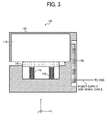
- FIG. 3 illustrates the configuration of a sensor device 100 according to an example embodiment of the present invention.
- the sensor device 100 includes an optical system 110, a processing device 130, a supporting member 140, a housing 150, and a plurality of spring members 170.
- the wall on the -Y side of the housing 150 is removed for ease of illustration of the inner structure.
- FIGS. 4A to 4C illustrate the housing 150 according to an example embodiment of the present invention.
- a slit is formed on the -X-side surface, and the slit penetrates to the +Y-side surface and the -Y-side surface.
- the housing 150 has a slit of prescribed length in the direction in which the recording paper is inserted.
- FIG. 5 illustrates the XZ cross section of the housing 150 according to an example embodiment of the present invention.
- the housing 150 has inner space in which the optical system 110, the processing device 130, the supporting member 140, and the spring members 170 are accommodated.
- FIGS. 6A to 6C illustrate the supporting member 140 according to an example embodiment of the present invention.
- the supporting member 140 has a supporting surface on the +Z side parallel to the XY surface, and supports the recording paper by that supporting surface.
- a tapered surface (inclined plane surface) is formed to guide the recording paper to the supporting surface.
- an inclined curved surface may be formed in place of the tapered surface.
- Such a curved surface has a round surface at an edge on the -X side of the supporting surface.
- FIG. 7 illustrates the spring members 170 according to an example embodiment of the present invention.
- the -Z-side edges of the spring members 170 are fixed to the housing 150, and the +Z-side edges of the spring members 170 are fixed to the -Z side surface of the supporting member 140.
- the supporting member 140 is attached to the housing 150 through the spring members 170.
- FIG. 8 illustrates the relative positions of the optical system 110, the supporting member 140, and recording paper M when the recording paper M is inserted into the slit, according to an example embodiment of the present invention.
- the optical system 110 is disposed on the +Z-side of the supporting member 140.
- the supporting member 140 is pressed down by the recording paper M, and the recording paper M is fed between the -Z-side of a dark box 119 of the optical system 110 and the supporting surface of the supporting member 140.
- the recording paper M that is inserted into the slit is on the -Z side of the optical system 110.
- FIG. 9 illustrates the configuration of the optical system 110 according to an example embodiment of the present invention.
- the optical system 110 includes a light source 111, a collimate lens 112, three photosensors 113, 114, and 115, a polarizing filter 116, and the dark box 119 that encloses these elements.
- the dark box 119 is a box made of metal such as aluminum, and the surface of the dark box 119 is anodized in black in order to reduce the influence of disturbance light and stray light.
- the dark box 119 is fixed to the housing 150.
- FIG. 10 illustrates the relative positions of the optical system 110 and a slit according to an example embodiment of the present invention.
- the position of the -Z-side surface of the dark box 119 is equal to the +Z-side surface of the slit of the housing 150.
- the position of the -Z-side surface of the dark box 119 in the Z-axis direction is not limited to the above configuration, but may be positioned above the slit of the housing 150.
- the supporting member 140 Before the recording paper M is inserted into the slit, the supporting member 140 is pressed by the spring members 170 towards the +Z-direction, such that the supporting surface of the supporting member 140 softly touches the -Z-side surface of the dark box 119.
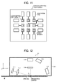
- FIG. 11 illustrates a surface emitting laser array according to an example embodiment of the present invention.
- the light source 111 includes a plurality of light-emitting units. Each of the light-emitting units is a vertical cavity-surface emitting laser (VCSEL). In other words, the light source 111 includes a vertical cavity-surface emitting laser array (VCSEL array). In the present example embodiment described above, as illustrated in FIG. 11 , nine light-emitting units are two-dimensionally arranged in the VCSEL array.
- VCSEL vertical cavity-surface emitting laser
- the light source 111 is disposed so as to irradiate the recording paper M with the s-polarized linear light.
- FIG. 12 illustrates the angle of incidence ⁇ of irradiation light on recording paper, according to an example embodiment of the present invention. In the present example embodiment, the angle of incidence ⁇ is 80°.
- the light source 111 is switched on and switched off by the processing device 130.
- the collimate lens 112 is disposed on the optical path of the light emitted from the light source 111, and collimates the light.
- the light that has passed the collimate lens 112 passes through the opening of the dark box 119 to irradiate the recording paper M.
- the center of the irradiated area on the surface of the recording paper M is referred to simply as a "irradiation center”.
- the light that has passed through the collimate lens 112 may be referred to as irradiation light.
- the plane that includes the incident light beam and the normal line drawn from the point of incidence of the boundary surface is referred to as the incidence plane.
- the incident light includes a plurality of light beams
- an incidence plane exists for each of the light beams.
- the incidence plane of the light beam incident on the irradiation center is referred to as the incidence plane of the recording paper M.
- the plane that includes the irradiation center and is parallel with the XZ-plane is the incidence plane of the recording paper M.
- the terms "s-polarized light” and "p-polarized light” are used not only for the incident light on the recording paper M but also for the reflection light. This is for the purpose of simplification, and the linearly polarized light whose polarization direction is the same as that of the incident light (i.e., s-polarized light) on an incidence plane is referred to as the s-polarized light, and the linearly polarized light whose polarization direction is orthogonal to the s-polarized light is referred to as the p-polarized light. These terms are used with reference to the polarization direction of the incident light on the recording paper M.
- the polarizing filter 116 is arranged on the +Z-side of the irradiation center.
- the polarizing filter 116 transmits the p-polarized light and blocks the s-polarized light.
- the polarizing filter 116 may be replaced with a polarization beam splitter whose capability is equivalent to that of the polarizing filter 116.
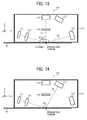
- FIG. 13 illustrates the relative positions of the photosensor 113 and the photosensor 114 according to an example embodiment of the present invention.
- the photosensor 114 is disposed on the +Z-side of the polarizing filter 116, and receives the light that has passed through the polarizing filter 116.
- the angle ⁇ 1 which the surface of the recording paper M forms with a line L1, which is drawn through the irradiation center, the center of the polarizing filter 116, and the center of the photosensor 114 is 90 degrees.
- the photosensor 113 is arranged on +X side of the irradiation center, with reference to the X-axis direction. As illustrated in FIG. 13 , the angle ⁇ 2 which the surface of the recording paper M forms with a line L2, which is drawn through the irradiation center and the center of the photosensor 113, is 170 degrees.
- FIG. 14 illustrates the arrangement of a third photosensor according to an example embodiment of the present invention.
- the photosensor 115 is arranged between the photosensor 114 and the photosensor 113, with reference to the X-axis direction.
- the angle ⁇ 3 which the surface of the recording paper M forms with a line L3, which is drawn through the irradiation center and the center of the photosensor 115, is 120 degrees.
- the center of the light source 111, the irradiation center, the center of the polarizing filter 116, the centers of the photosensors 113, 114, and 115 are substantially on the same plane.
- the direction in which the light source 111 and the photosensors 113, 114, and 115 are arranged is not limited to the above configuration.
- the direction in which the light source 111 and the photosensors 113, 114, and 115 are arranged may be orthogonal to the direction in which the recording paper is inserted, or may be inclined towards the direction in which the recording paper is inserted.
- FIG. 15A illustrates surface regular reflection light
- FIG. 15B illustrates surface diffuse reflection light
- the light reflected from recording paper when the recording paper is irradiated with light is classified into two kinds of reflected light, consisting of the light reflected at the surface of the recording paper, and the light reflected inside the recording paper.
- the light reflected at the surface of the recording paper is classified into two kinds of reflected light, consisting of the light of regular reflection and the light of diffuse reflection.
- the light reflected by regular reflection on the recording paper is referred to as "surface regular reflection light”
- the light reflected by diffuse reflection is referred to as "surface diffuse reflection light” for the purpose of simplification, as illustrated in FIGS. 15A and 15B .
- the surface of recording paper is composed of plane portions and oblique portions, and the smoothness of the recording paper is determined by the ratio of the plane portions to the oblique portions.
- the light reflected at a plane portion becomes surface regular reflection light
- the light reflected at an oblique portion becomes surface diffuse reflection light.
- the surface diffuse reflection light is completely-dispersed reflection light, and it is assumable that the direction of reflection is isotropic. When the smoothness is high, the light quantity of the surface regular reflection light increases accordingly.
- FIG. 15C illustrates internal reflection light.
- the reflected light from the inside of the recording paper is composed of only diffuse reflection light because multiple scattering occurs inside the fibers of the recording paper.
- the reflected light from the inside of the recording paper is referred to as "internal reflection light" for the purpose of simplification, as illustrated in FIG. 15C .
- the internal reflection light is also completely-dispersed reflection light in a similar manner to the surface diffuse reflection light, and it is assumable that the direction of reflection is isotropic.
- the polarization direction of the surface regular reflection light and surface diffuse reflection light towards a photosensor is the same as the polarization direction of the incident light. Note that the polarization direction rotates on the surface of recording paper only when the incident light is reflected on a part of the surface that is inclined in the direction of the rotation with reference to the incident direction. Because the center of the light source, the irradiation center, and the centers of the photosensors are substantially on a same plane, the light whose polarization direction is rotated on the surface of recording paper is not reflected to any of the photosensors.
- the polarization direction of the internal reflection light is rotated with reference to the polarization direction of the incident light. This happens as the light that enters recording paper is transmitted through fibers and is subject to optical rotation while experiencing multiple scattering, and the polarization direction is rotated.
- FIG. 16 illustrates the reflected light that enters the polarization filter 116, according to an example embodiment of the present invention. As illustrated in FIG. 16 , reflection light including the surface diffuse reflection light and internal reflection light enters the polarizing filter 116.
- the surface diffuse reflection light has the s-polarized light same as that of the incident light, the surface diffuse reflection light that enters the polarizing filter 116 is blocked at the polarizing filter 116.
- the internal reflection light has both the s-polarized light and p-polarized light, and the p-polarized light passes through the polarizing filter 116.
- the p-polarized light included in the internal reflection light is received at the photosensor 114.
- FIG. 17 illustrates the light received by the photosensor 114, according to an example embodiment of the present invention.
- the p-polarized light included in the internal reflection light may be referred to as "p-polarized internal reflection light" for the purpose of simplification.
- the s-polarized light included in the internal reflection light may be referred to as "s-polarized internal reflection light”.
- the amount of the p-polarized internal reflection light correlates with the thickness or density of recording paper. This is because the amount of the p-polarized internal reflection light is dependent upon the length of the path where the light passes through the fibers of the recording paper.
- FIG. 18 illustrates the light received by the photosensor 113, according to an example embodiment of the present invention.
- reflection light including the surface regular reflection light, surface diffuse reflection light, and internal reflection light enters the photosensor 113.
- the amount of the surface diffuse reflection light and internal reflection light is very small compared with the amount of the surface regular reflection light. For this reason, it can be assumed that the amount of the light received at the photosensor 113 is substantially equivalent to the amount of the surface regular reflection light.
- reflection light including the surface diffuse reflection light and internal reflection light enters the photosensor 115.
- the amount of the internal reflection light is very small compared with the amount of the surface diffuse reflection light. For this reason, it can be assumed that the amount of the light received at the photosensor 115 is substantially equivalent to the amount of the surface diffuse reflection light.
- Each of the photosensors transmits an electrical signal to the processing device 130 based on the amount of the received light.
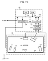
- FIG. 19 illustrates the configuration of the processing device 130 according to an example embodiment of the present invention.
- the processing device 130 includes a central processing unit (CPU) 131, a read only memory (ROM) 132, a random access memory (RAM) 133, a light source drive circuit 134, a current/voltage converter 135, and an analog-to-digital (A/D) converter 136.
- the power is supplied to the processing device 130 from the printer controller 2090 through a cable, and the processing device 130 is controlled by the printer controller 2090 through a wired interface such as a universal serial bus (USB) or RS-232C.
- USB universal serial bus
- RS-232C RS-232C
- the ROM 132 stores a program described by codes readable by the CPU 131 and various kinds of data used for executing the program.
- the RAM 133 serves as a working memory.
- the light source drive circuit 134 transmits a light-source driving signal to the light source 111 in accordance with the instructions provided by the CPU 131.
- the current/voltage converter 135 converts the current signal output from the photosensors into a voltage signal.
- the A/D converter 136 converts the voltage signal output from the current/voltage converter 135 from an analog signal to a digital signal.
- the CPU 131 identifies the brand of recording paper according to the program stored in the ROM 132.
- the printer controller 2090 is notified of the result of identification.
- FIGS. 20A to 20C illustrate how the supporting member 140 moves when the recording paper M is inserted into a slit, according to an example embodiment of the present invention.
- FIG. 21 illustrates the pressing force exerted by the spring members 170 on the supporting member 140, according to an example embodiment of the present invention.
- the recording paper M in full contact with the optical system 110.
- the irradiation position or angle of incidence of the light is fixed with reference to the recording paper M, and a stable amount of reflection light can be obtained.
- an improved precision is achieved in identifying the brand of the recording paper M. If the recording paper M is not in full contact with the optical system 110, the irradiation position or angle of incidence of the light fluctuates, and the brand of the recording paper M cannot be identified with precision.
- the optical system 110 becomes completely closed and the noise generated by disturbance light can be prevented. Further, the light (laser light) can be prevented from leaking to the outside of the sensor device 100, and the security for an operator is improved accordingly.
- the intensity of the pressing force applied to the supporting member 140 by the spring members 170 is controlled such that an operator can easily pull out the recording paper M from the sensor device 100.
- the holding force applied to the recording paper M by the optical system 110 and the supporting member 140 is controlled such that the recording paper M can smoothly move without being caught in the sensor device 100 when the recording paper M is moved relative to the sensor device 100. If the pressing force applied to the recording paper M is too great, it may become difficult to smoothly move the recording paper M, or the recording paper M may be damaged when the recording paper M is moved relative to the sensor device 100. On the other hand, if the pressing force applied to the recording paper M is too weak, a gap is created between the recording paper M and the optical system 110, and the brand of the recording paper M can not be identified with precision.
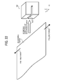
- FIG. 22 illustrates the pulling force applied to recording paper when the recording paper is inserted into a slit, according to an example embodiment of the present invention.
- a slit is provided on the -X-side surface of the housing 150 to which the recording paper is inserted, and the slit penetrates to +Y-side surface and the -Y-side surface that are adjacent to the -X-side surface. Accordingly, in the present example embodiment, as illustrated in FIG.
- a plurality of brands of recording paper which are compatible with the color printer 2000, are inserted into the slit of sensor device 100, and the output levels of the photosensors when the light source 111 is switched on are obtained.
- the results of the above obtaining processes are stored in the ROM 132 of the processing device 130 as "brand-specific output level data".
- the brand-specific output level data refers to a database in which the output levels of the photosensors, which are obtained for the already-known different brands of recording paper, are recorded.
- FIG. 23 illustrates brand-specific output level data according to an example embodiment of the present invention.
- the output levels of the photosensor 113, the photosensor 114, and the photosensor 115 are referred to as S1, S2, and S3, respectively.
- the sensor device 100 is placed on the flat surface arranged near the operation panel. 2. To-be-identified recording paper is inserted into the slit of the sensor device 100 with tension (pulling force) being applied to both sides of the recording paper in the Y-axis direction. 3. A request for an identification process is made through the operation panel.
- This request for an identification process is sent to the processing device 130 of the sensor device 100 through the operation panel and the printer controller 2090.
- FIG. 24 is a flowchart of a series of computational algorithms executed by the CPU 131 of the processing device 130 when brand identification processes are performed.
- a variable tc that indicates the value of a time counter is initialized with 0.
- the variable tc is increased by 1 (+1) for every 10 milliseconds (msec) in the interruption process of a timer.
- a variable m that indicates the number of times the signals output from photosensors have been obtained is initialized with 0.
- step S405 the light source 111 is switched on.
- a plurality of light-emitting units are switched on at the same time.
- step S407 whether or not the variable tc is equal to or greater than "300" is determined. In other words, whether or not three seconds have passed since the light source 111 was switched on is determined. When this determination is negative, the process shifts to step S409.
- step S409 the signals output from photosensors are obtained.
- step S413 the data obtained in step S409 is stored in the RAM 133 together with the value of the variable m. Then, the process returns to step S407.
- steps S409 to S413 are repeated until the determination in step S407 becomes positive.
- step S407 When the determination becomes positive in step S407, the process shifts to step S415.
- step S415 the light source 111 is switched off. Assuming that the value of the variable m is "P”, P pieces of data are stored in the RAM 133 for each of the photosensors.
- step S417 a mean value of P output levels is calculated for each photosensor.
- the mean values of the output level of the photosensor 113, the photosensor 114, and the photosensor 115 are referred to as S1', S2', and S3', respectively.
- S1', S2', and S3' are used as measurement data.
- step S419 the brand-specific output level data stored in the ROM 132 is referred to, and a relevance ratio R is calculated for each brand by using formula (1) below.
- R 1 - S ⁇ 1 - S ⁇ 1 ⁇ ⁇ S ⁇ 1 + S ⁇ 1 ⁇ ⁇ ⁇ 1 - S ⁇ 2 - S ⁇ 2 ⁇ ⁇ S ⁇ 2 + S ⁇ 2 ⁇ ⁇ ⁇ 1 - S ⁇ 3 - S ⁇ 3 ⁇ ⁇ S ⁇ 3 + S ⁇ 3 ⁇ ⁇ ⁇ ⁇
- step S421 the brand for which the calculated relevance ratio R becomes the greatest is identified as the brand of the recording paper.
- step S423 the printer controller 2090 is notified of the identified brand of the recording paper. Then, the brand identification process is terminated.
- FIGS. 25A and 25B illustrate the relative movement of recording paper according to an example embodiment of the present invention.
- FIG. 26 illustrates a plurality of detection positions according to an example embodiment of the present invention.
- An operator may move at least one of the sensor device 100 and the recording paper M, as illustrated in FIGS. 25A and 25B , while the light source 111 is being switched on in the brand identification processes.
- different P positions on the recording paper M are used as detection positions, as illustrated in FIG. 26 . Accordingly, nonuniformity in the state of surface or the density of the fiber of the recording paper is averaged, and measurement can be performed with minimized effect of such nonuniformity. Accordingly, identification accuracy can be improved.
- the P positions are not necessarily equally spaced.
- the direction in which the sensor device 100 or the recording paper M is moved is not limited to the Y-axis direction.
- the direction in which the sensor device 100 or the recording paper M is moved may be the direction in which the recording paper M is pulled out from the sensor device 100 (i.e., the -X direction in the present example embodiment).
- the printer controller 2090 controls the display unit of the operation panel to display the brand of the recording paper identified by the sensor device 100, and stores the identification results in the RAM of the printer controller 2090.
- the identified brand of the recording paper is displayed on the display unit of the operation panel
- an operator returns the sensor device 100 to the originally disposed position. Then, the operator sets the recording paper of the specified brand to the paper feed tray 2060.
- the brand of the recording paper displayed on the display unit of the operation panel may be registered into the printer controller 2090 by using the keys on the operation panel.
- the printer controller 2090 reads the brand of the recording paper from the RAM when a request for a print job is received, and then determines optimal developing conditions and transferring conditions from the development and transfer table for the specified brand of the recording paper.
- the printer controller 2090 controls the development device and transfer device of each station in accordance with the determined optimal developing conditions and transferring conditions. For example, the printer controller 2090 controls the transfer voltage or the amount of toner. Accordingly, a high-quality image is formed on recording paper.
- the sensor device 100 includes the optical system 110, the processing device 130, the supporting member 140, the housing 150, and the spring members 170.
- the housing 150 has a slit into which recording paper is inserted to identify the brand of the recording paper.
- recording paper is inserted into the slit, the recording paper is sandwiched between the optical system 110 and the supporting member 140.
- the supporting member 140 is attached to the housing 150 through the spring members 170.
- pressing force is applied by the spring members 170 in the +Z-direction of the supporting member 140.
- the CPU 131 of the processing device 130 measures the output levels of the photosensors when the light source 111 of the optical system 110 is switched on to irradiate to-be-identified recording paper with light, and calculates a relevance ratio R by referring to the brand-specific output level data and using the formula (1) described above. Further, the CPU 131 identifies the brand of the to-be-identified recording paper based on the calculated relevance ratio R.
- inexpensive metal springs may be used as the spring members 170.
- a variety of such inexpensive metal springs are commercially available and easily accessible. Accordingly, a sensor device can be realized at low cost.
- a polarizing filter is not required to obtain linearly polarized light as irradiation light.
- the use of a surface emitting laser array realizes high-density integration of a plurality of light-emitting units, which was difficult to achieve with the conventional LEDs or the like. In such cases, a small-sized light source having a plurality of light-emitting units can be realized.
- the laser light can be all condensed to the optical axis of a collimate lens, and a plurality of rays of light can be collimated with a fixed angle of incidence. In other words, a collimate optical system can be realized at low cost. Accordingly, the cost and size of an optical system can be reduced.
- the signal-to-noise ratio improves in the output of the photosensors, and identification accuracy also improves.
- the contrast ratio of the speckle pattern of reflection light decreases by switching on all the light-emitting units at the same time, and the amount of reflection light can be measured more accurately. Accordingly, the identification accuracy improves.
- the light quantity of the internal reflection light can be increased by switching on the light-emitting units at the same time. Accordingly, it becomes possible to achieve precise separation of the internal reflection light in the optical system 110. Conventionally, such separation of the light reflected from the inside of recording paper was difficult to achieve.
- the reflection light from the inside of recording paper includes the information about the inside state of the recording paper.
- the CPU 131 of the processing device 130 identifies the brand of recording paper based on the signals output from the three photosensors. By taking into consideration the information about the inside state of the recording paper, it becomes possible to improve the level of paper identification such that the level of the recording paper can be determined. Conventionally, such identification of brand was difficult.
- the sensor device 100 according to the present example embodiment can precisely identify an object with simple configuration.
- the color printer 2000 according to the present example embodiment can form a high-quality image without increasing the cost or size. Further, troublesome manual settings or failure in printing due to a setting error, which are still present in the conventional products, can be eliminated according to the present example embodiment.
- FIG. 27 illustrates a first modification (1) of a sensor device according to an example embodiment of the present invention.
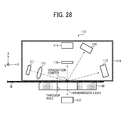
- FIG. 28 illustrates a first modification (2) of a sensor device according to an example embodiment of the present invention.
- a through hole may be made through the supporting member 140 directly below the opening of the dark box 119 (on the -Z-side), and a photosensor 117 may be provided to receive transmission light that has passed through the recording paper M.
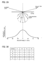
- FIG. 29 illustrates the characteristics of transmission light according to an example embodiment of the present invention.
- the light that has entered the paper is dispersed by the fibers of the paper, and has an angle distribution that is not dependent on the angle of incidence, where the peak is at the light intensity of the direction orthogonal to the surface of the paper. For this reason, it is desired that the photosensor 117 be arranged directly underneath the irradiation center.
- the identification accuracy of recording paper can be improved by measuring the amount of the transmission light in consideration of the basis weight of the recording paper, as described above.
- FIG. 30 illustrates brand-specific output level data that corresponds to the first modification of a sensor device, according to an example embodiment of the present invention.
- the output level of the photosensor 117 is referred to as S4 in the brand-specific output level data
- a mean value of the output levels of the photosensor 117 when to-be-identified recording paper is irradiated with light is referred to as S4'.
- R 1 - S ⁇ 1 - S ⁇ 1 ⁇ ⁇ S ⁇ 1 + S ⁇ 1 ⁇ ⁇ ⁇ 1 - S ⁇ 2 - S ⁇ 2 ⁇ ⁇ S ⁇ 2 + S ⁇ 2 ⁇ ⁇ ⁇ 1 - S ⁇ 3 - S ⁇ 3 ⁇ ⁇ S ⁇ 3 + S ⁇ 3 ⁇ ⁇ ⁇ 1 - S ⁇ 4 - S ⁇ 4 ⁇ ⁇ S ⁇ 4 + S ⁇ 4 ⁇ ⁇ ⁇ ⁇
- the optical system 110 includes three photosensors for receiving reflection light were described. However, no limitation is indicated therein, and the optical system 110 may include any number of photosensors depending on the desired identification accuracy.
- FIG. 31 illustrates a second modification of the sensor device 100 according to an example embodiment of the present invention.
- the optical system 110 according to the example embodiment described above from which the photosensor 115 is removed is illustrated.
- FIG. 32 illustrates a third modification (1) of the sensor device 100 according to an example embodiment of the present invention.
- the optical system 110 according to the example embodiment described above to which a photosensor 120 and a polarizing filter 121 are added is illustrated.
- the polarizing filter 121 is arranged on the optical path of reflection light including the surface diffuse reflection light and internal reflection light.
- the polarizing filter 121 transmits the p-polarized light and blocks the s-polarized light.
- the photosensor 120 is arranged on the optical path of the light that has passed through the polarizing filter 121.
- the photosensor 120 receives the p-polarized light included in the internal reflection light.
- FIG. 33 illustrates a third modification (2) of the sensor device 100 according to an example embodiment of the present invention.
- the angle ⁇ 4 which the surface of the recording paper M forms with a line L4, which is drawn through the irradiation center and the centers of the polarizing filter 121 and photosensor 120 is 150 degrees.
- the center of the light source 111, the irradiation center, the centers of the polarizing filters, the centers of the photosensors are substantially on the same plane.
- FIG. 34 illustrates brand-specific output level data that corresponds to the third modification of the sensor device 100, according to an example embodiment of the present invention.
- the output level of the photosensor 120 is referred to as S5 in the brand-specific output level data
- a mean value of the output levels of the photosensor 120 when to-be-identified recording paper is irradiated with light is referred to as S5'.
- R 1 - S ⁇ 1 - S ⁇ 1 ⁇ ⁇ S ⁇ 1 + S ⁇ 1 ⁇ ⁇ ⁇ 1 - S ⁇ 2 - S ⁇ 2 ⁇ ⁇ S ⁇ 2 + S ⁇ 2 ⁇ ⁇ ⁇ 1 - S ⁇ 3 - S ⁇ 3 ⁇ ⁇ S ⁇ 3 + S ⁇ 3 ⁇ ⁇ ⁇ 1 - S ⁇ 5 - S ⁇ 5 ⁇ ⁇ S ⁇ 5 + S ⁇ 5 ⁇ ⁇ ⁇ ⁇
- FIG. 35 illustrates a sensor for detecting the insertion of recording paper, according to an example embodiment of the present invention.
- the sensor device 100 may be provided with a sensor 125 that detects the insertion of the recording paper M.
- the sensor 125 includes a light emitting element 125a and a light receiving element 125 b that are arranged to face each other in the Z-axis direction. When the light emitted from the light emitting element 125a is received by the light receiving element 125b, it is determined that "no recording paper is inserted".
- the sensor 125 is a so-called transmission photo interrupter sensor.
- a different type of sensor may also be used. In other words, any sensor may be used as long as that sensor can detect the insertion of recording paper.
- the light source 111 and the related processes may be controlled as follows.
- the light source 111 is switched on and the output of the photosensors is obtained when it is determined that "recording paper is inserted".
- the light source 111 is switched off and data processing is performed when it is determined that "no recording paper is inserted”.
- it can be configured such that measurement will be performed only when recording paper is inserted into the slit. Accordingly, measurement is not erroneously performed when no recording paper is inserted.
- it may be configured such that measurement will start automatically without any instruction through the operation panel, or power consumption may be reduced by minimizing the length of time during which the light source 111 is switched on.
- the sensor device 100 may be provided with an LED that illuminates when it is determined that "recording paper is inserted”. Due to such provision of an LED, an operator can visually notice that recording paper has been inserted.
- At least some of the processes performed by a program, which is executed by the CPU 131, may be performed by hardware, or all of the processes may be performed by hardware.
- recording paper is irradiated with the s-polarized light
- recording paper may be irradiated with the p-polarized light.
- a polarizing filter that transmits the s-polarized light is used in place of the polarizing filter 116, and the photosensor 114 receives the s-polarized light included in the internal reflection light.
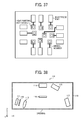
- FIG. 37 illustrates a modification of a surface emitting laser array according to an example embodiment of the present invention. As illustrated in FIG. 37 , at least some of light-emitting units of a surface emitting laser array may be spaced differently from the other light-emitting units. In other words, the space between adjacent light-emitting units may vary.
- a conventional laser diode may be used in place of the surface emitting laser array.
- FIG. 38 illustrates a fourth modification of the sensor device 100 according to an example embodiment of the present invention.
- a polarizing filter 126 is provided to obtain s-polarized light from the light emitted from the light source 111.
- FIG. 39 illustrates a fifth modification (1) of the sensor device 100 according to an example embodiment of the present invention.
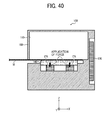
- FIG. 40 illustrates a fifth modification (2) of the sensor device 100 according to an example embodiment of the present invention.
- a plurality of rubber members 174 may be used in place of the spring members 170.
- a porous resin member such as a sponge may be used in place of the spring members 170.
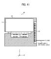
- FIG. 41 illustrates a sixth modification (1) of the sensor device 100 according to an example embodiment of the present invention.
- FIG. 42 illustrates a sixth modification (2) of the sensor device 100 according to an example embodiment of the present invention.
- a plurality of magnets 176 may be used in place of the spring members 170.
- the repulsive force caused between two magnets that are disposed in the Z-axis direction is used.
- spring members or rubber members become deteriorated due to aging and become incapable of appropriately maintaining the holding force. For this reason, long-term use of spring members and rubber members is to be avoided.
- repulsive force does not deteriorate easily when magnets are used. For this reason, magnets are suitable for long-term use. Magnets may be arranged to use the attractive force between two magnets.
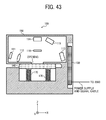
- FIG. 43 illustrates a seventh modification (1) of the sensor device 100 according to an example embodiment of the present invention.
- the dark box 119 may be omitted as illustrated in FIG. 43 .
- FIG. 44 illustrates a seventh modification (2) of the sensor device 100 according to an example embodiment of the present invention.
- the housing 150 does the job of the -Z-side surface of the dark box 119, as illustrated in FIG. 44 .
- the printer controller 2090 may perform brand identification processes.
- the brand-specific output level data may be stored in a ROM of the printer controller 2090.
- a start button for the identification process may be provided for the sensor device 100. In that case, it is not necessary for an operator to input a request for an identification process through the operation panel.
- an LED that indicates the on/off of the light source 111 may be provided for the sensor device 100. Due to such provision of an LED, an operator can visually know the on/off of the light source 111.
- a display unit may be provided for the sensor device 100.
- the processing device 130 controls the display unit to display the identification results.
- the outside shape of the housing 150 of the sensor device 100 is like a block were described.
- the outside shape of the housing 150 may have a curve like a mouse.
- the housing 150 may have any outside shape as long as the housing 150 has a slit of prescribed length in the direction in which the recording paper is inserted.
- an object to be identified by the sensor device 100 is not limited to recording paper.
- the recording paper may be held by electrostatic force instead of the pressing force, or the recording paper may be held by suction (negative pressure).
- FIG. 45 illustrates an irradiation area according to an example embodiment of the present invention.
- the shape of an irradiation area is elliptic where the major (longer) axis is the X axis and the minor (shorter) axis is the Y axis.
- the length of the minor axis (BM1) is 2.3 mm
- the length of the major axis (BM2) is 13.4 mm.
- the opening made on the dark box 119 is made along the circumference of the irradiation area and the size is as small as possible, as long as the opening does not cover the irradiation area.
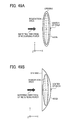
- FIG. 46 illustrates a desired shape of an opening according to an example embodiment of the present invention.
- some margin is provided in consideration of tolerance or adjustment of beam
- a preferred shape of the opening is, as illustrated in FIG. 46 , a rectangle where the length in the Y-axis direction (K1) is 4 mm and the length in the X-axis direction (K2) is 15 mm.
- the opening is shaped to have the longitudinal direction parallel to the direction in which a light source and a plurality of photosensors are arranged (i.e., X-axis direction).
- the opening is narrower than the irradiation area and some of the irradiation area is covered by the -Z-side surface of the dark box 119, the light reflected at the -Z-side surface of the dark box 119 become stray light, and such stray light may be received by a photosensor. In that case, the signal-to-noise ratio (S/N) of the signal output from the photosensor decreases, and the identification accuracy deteriorates.
- S/N signal-to-noise ratio
- the opening may be shaped differently from the preferred configuration described above. As long as an opening is arranged on a part of the -Z-side surface of the dark box 119, recording paper can be held by the -Z-side surface of the dark box 119.
- FIG. 47 illustrates a first modification of an opening according to an example embodiment of the present invention.
- the center of the edge that is on the leading-end side of the direction in which the recording paper is inserted i.e., on the +X side
- the center of the edge that is on the leading-end side of the direction in which the recording paper is inserted i.e., on the +X side
- the center of the edge that is on the leading-end side of the direction in which the recording paper is inserted i.e., on the +X side
- the center of the edge that is on the leading-end side of the direction in which the recording paper is inserted i.e., on the +X side
- FIG. 48 illustrates the arrangement of a light source and a plurality of photosensors with reference to an opening of a modification, according to an example embodiment of the present invention. Note that, as illustrated in FIG. 48 , the direction in which light source and a plurality of photosensors are arranged is the Y-axes direction, which is different from the example embodiment described above.
- the above-described edge of the opening is convexly curved towards the direction in which the recording paper is inserted, and the center of the above-described edge is positioned on a further leading-end side of the insertion direction than at least one of the two ends of the edge.
- FIG. 49A illustrates a second modification of an opening according to an example embodiment of the present invention.
- the shape of the opening is elliptic.
- the above-described edge of the opening is convexly curved towards the direction in which the recording paper is inserted, and the center of the above-described edge is positioned on a further leading-end side of the insertion direction than at least one of the two ends of the edge.
- FIG. 49B illustrates a third modification of an opening according to an example embodiment of the present invention.
- the shape of the opening is semiellptic.
- the above-described edge of the opening is convexly curved towards the direction in which the recording paper is inserted, and the center of the above-described edge is positioned on a further leading-end side of the insertion direction than at least one of the two ends of the edge.
- FIG. 50A illustrates a fourth modification of an opening according to an example embodiment of the present invention.
- the shape of the opening is triangular.
- the above-described edge is composed of two sides of a triangle, and the point of intersection of these two sides is the center of the edge.
- the center of the above-described edge is positioned on a further leading-end side of the insertion direction than at least one of the two ends of the edge.
- FIG. 50B illustrates a fifth modification of an opening according to an example embodiment of the present invention.
- the opening is shaped like a parallelogram.
- the above-described edge of the opening is a straight line that is inclined with reference to the direction orthogonal to the direction in which the recording paper is inserted, and the center of the above-described edge is positioned on a further leading-end side of the insertion direction than at least one of the two ends of the edge (i.e., the end on the -Y side).
- FIGS. 51A and 51B illustrate other methods of preventing recording paper from being caught at an edge of an opening, according to an example embodiment of the present invention.
- the direction in which light source and a plurality of photosensors are arranged may be inclined with reference to the direction in which the recording paper is inserted.
- FIG. 51B even if the opening is rectangular, it becomes possible to prevent the recording paper from being caught at an edge of the opening.
- the above-described edge of the opening is the long side of the parallelogram on the +X side, and the center of the above-described edge is positioned on a further leading-end side of the insertion direction than at least one of the two ends of the edge (i.e., the end on the -Y side).
- the color printer 2000 is used as an image forming apparatus, but no limitation is indicated therein.
- a laser printer that forms monochrome images may be used as an image forming apparatus.
- an image forming apparatus other than a printer for example, a copier, a facsimile, or a multifunction peripheral (MFP) into which these elements are integrated, may be used.
- MFP multifunction peripheral
- an image forming apparatus includes four photoreceptor drums were described, but no limitation is indicated therein.
- a printer for which five photoreceptor drums are provided may be used as an image forming apparatus.
- the sensor device 100 may be applied to an image forming apparatus in which an image is formed by ejecting ink onto recording paper.
Landscapes
- Physics & Mathematics (AREA)
- Life Sciences & Earth Sciences (AREA)
- Chemical & Material Sciences (AREA)
- Health & Medical Sciences (AREA)
- General Physics & Mathematics (AREA)
- Pathology (AREA)
- Immunology (AREA)
- Analytical Chemistry (AREA)
- Biochemistry (AREA)
- General Health & Medical Sciences (AREA)
- Engineering & Computer Science (AREA)
- Food Science & Technology (AREA)
- Medicinal Chemistry (AREA)
- Microelectronics & Electronic Packaging (AREA)
- Control Or Security For Electrophotography (AREA)
- Investigating Or Analysing Materials By Optical Means (AREA)
- Controlling Sheets Or Webs (AREA)
- Electrophotography Configuration And Component (AREA)
- Length Measuring Devices By Optical Means (AREA)
Applications Claiming Priority (2)
| Application Number | Priority Date | Filing Date | Title |
|---|---|---|---|
| JP2013188965 | 2013-09-12 | ||
| JP2014130734A JP6394943B2 (ja) | 2013-09-12 | 2014-06-25 | センサ装置及び画像形成装置 |
Publications (3)
| Publication Number | Publication Date |
|---|---|
| EP2848915A2 true EP2848915A2 (de) | 2015-03-18 |
| EP2848915A3 EP2848915A3 (de) | 2015-04-29 |
| EP2848915B1 EP2848915B1 (de) | 2020-05-20 |
Family
ID=51492178
Family Applications (1)
| Application Number | Title | Priority Date | Filing Date |
|---|---|---|---|
| EP14183439.0A Active EP2848915B1 (de) | 2013-09-12 | 2014-09-03 | Sensorvorrichtung und Bilderzeugungsvorrichtung damit |
Country Status (4)
| Country | Link |
|---|---|
| US (1) | US20150071658A1 (de) |
| EP (1) | EP2848915B1 (de) |
| JP (1) | JP6394943B2 (de) |
| CN (1) | CN104460279B (de) |
Cited By (1)
| Publication number | Priority date | Publication date | Assignee | Title |
|---|---|---|---|---|
| EP2945018B1 (de) * | 2014-05-14 | 2021-08-11 | Ricoh Company, Ltd. | Sensorvorrichtung, bilderzeugungsvorrichtung und steuerungsverfahren für lichtquelle |
Families Citing this family (4)
| Publication number | Priority date | Publication date | Assignee | Title |
|---|---|---|---|---|
| JP7200650B2 (ja) * | 2018-12-14 | 2023-01-10 | コニカミノルタ株式会社 | 物性測定装置および画像形成装置 |
| JP7415779B2 (ja) * | 2020-05-08 | 2024-01-17 | コニカミノルタ株式会社 | 画像形成システム、画像形成装置及びプログラム |
| JP7409229B2 (ja) * | 2020-05-25 | 2024-01-09 | コニカミノルタ株式会社 | 画像形成システム、画像形成装置及び情報処理装置 |
| JP2023115983A (ja) * | 2022-02-09 | 2023-08-22 | キヤノン株式会社 | 識別装置、及び画像形成装置 |
Citations (2)
| Publication number | Priority date | Publication date | Assignee | Title |
|---|---|---|---|---|
| JP2004179721A (ja) | 2002-11-25 | 2004-06-24 | Kyocera Mita Corp | 画像処理装置,複写装置 |
| JP2012127937A (ja) | 2010-11-26 | 2012-07-05 | Ricoh Co Ltd | 光学センサ及び画像形成装置 |
Family Cites Families (23)
| Publication number | Priority date | Publication date | Assignee | Title |
|---|---|---|---|---|
| US3099750A (en) * | 1961-08-09 | 1963-07-30 | Eastman Kodak Co | Housing for photoelectric sensing unit |
| US4721968A (en) * | 1983-09-22 | 1988-01-26 | Canon Kabushiki Kaisha | Ink jet transparency-mode recorder |
| JPH079069Y2 (ja) * | 1987-11-24 | 1995-03-06 | オムロン株式会社 | 生化学測定器のブランク値測定用反射板 |
| US4921365A (en) * | 1988-08-10 | 1990-05-01 | Royden C. Sanders, Jr. | High speed shuttle printer |
| JPH0790949B2 (ja) * | 1989-05-16 | 1995-10-04 | シャープ株式会社 | 用紙検知装置 |
| US5371614A (en) * | 1989-11-01 | 1994-12-06 | Tokyo Electric Co., Ltd. | Image scanner for film |
| JPH03240541A (ja) * | 1990-02-20 | 1991-10-25 | Canon Inc | 画像形成装置 |
| US5075543A (en) * | 1990-05-29 | 1991-12-24 | Xerox Corporation | Light weight paper sensor using fibers |
| US5233408A (en) * | 1992-01-27 | 1993-08-03 | Eaton Corporation | Color sensor adaptor bracket for measuring flexible translucent materials |
| US5289011A (en) * | 1992-11-30 | 1994-02-22 | Xerox Corporation | Sensor control system and method compensating for degradation of the sensor and indicating a necessity of service prior to sensor failure |
| WO1995019019A2 (en) * | 1994-01-04 | 1995-07-13 | Mars, Incorporated | Detection of counterfeits objects, for instance counterfeits banknotes |
| US6215552B1 (en) * | 1994-07-18 | 2001-04-10 | Xerox Corporation | Electrostatic process control based upon both the roughness and the thickness of a substrate |
| US5721434A (en) * | 1996-10-18 | 1998-02-24 | Xerox Corporation | Digital diagnostic system for optical paper path sensors |
| JP4290131B2 (ja) * | 2004-03-31 | 2009-07-01 | キヤノン株式会社 | 記録媒体識別装置および記録装置 |
| JP2006062842A (ja) * | 2004-08-27 | 2006-03-09 | Canon Inc | 画像形成装置 |
| US20060279624A1 (en) * | 2005-06-10 | 2006-12-14 | Akihiko Tsuchiya | Printer, printing control method for a printer and computer program for a printer |
| JP2008068413A (ja) * | 2006-09-12 | 2008-03-27 | Seiko Epson Corp | 印刷装置 |
| US20080193157A1 (en) * | 2007-02-14 | 2008-08-14 | Hewlett-Packard Development Company, L.P. | Media Determination |
| US7746980B1 (en) * | 2008-12-16 | 2010-06-29 | Bruker Axs Gmbh | X-ray reflectometry system with multiple sample holder and individual sample lifting mechanism |
| JP2012128393A (ja) * | 2010-11-26 | 2012-07-05 | Ricoh Co Ltd | 光学センサ及び画像形成装置 |
| JP5900726B2 (ja) * | 2011-09-05 | 2016-04-06 | 株式会社リコー | 光学センサ、画像形成装置及び判別方法 |
| JP5999305B2 (ja) * | 2012-02-20 | 2016-09-28 | 株式会社リコー | 光学センサ及び画像形成装置 |
| JP6283995B2 (ja) * | 2013-12-03 | 2018-02-28 | 株式会社リコー | シート材情報を検出する装置及び画像形成システム |
-
2014
- 2014-06-25 JP JP2014130734A patent/JP6394943B2/ja active Active
- 2014-09-02 CN CN201410443012.1A patent/CN104460279B/zh active Active
- 2014-09-03 EP EP14183439.0A patent/EP2848915B1/de active Active
- 2014-09-05 US US14/477,963 patent/US20150071658A1/en not_active Abandoned
Patent Citations (3)
| Publication number | Priority date | Publication date | Assignee | Title |
|---|---|---|---|---|
| JP2004179721A (ja) | 2002-11-25 | 2004-06-24 | Kyocera Mita Corp | 画像処理装置,複写装置 |
| JP3730210B2 (ja) | 2002-11-25 | 2005-12-21 | 京セラミタ株式会社 | 画像処理装置,複写装置 |
| JP2012127937A (ja) | 2010-11-26 | 2012-07-05 | Ricoh Co Ltd | 光学センサ及び画像形成装置 |
Cited By (1)
| Publication number | Priority date | Publication date | Assignee | Title |
|---|---|---|---|---|
| EP2945018B1 (de) * | 2014-05-14 | 2021-08-11 | Ricoh Company, Ltd. | Sensorvorrichtung, bilderzeugungsvorrichtung und steuerungsverfahren für lichtquelle |
Also Published As
| Publication number | Publication date |
|---|---|
| CN104460279A (zh) | 2015-03-25 |
| EP2848915B1 (de) | 2020-05-20 |
| US20150071658A1 (en) | 2015-03-12 |
| EP2848915A3 (de) | 2015-04-29 |
| JP2015078973A (ja) | 2015-04-23 |
| CN104460279B (zh) | 2018-11-13 |
| JP6394943B2 (ja) | 2018-09-26 |
Similar Documents
| Publication | Publication Date | Title |
|---|---|---|
| JP6355066B2 (ja) | センサ装置及び画像形成装置 | |
| KR101612599B1 (ko) | 센서 장치 및 화상 형성 장치 | |
| JP5999305B2 (ja) | 光学センサ及び画像形成装置 | |
| JP6083119B2 (ja) | 光学センサ及び画像形成装置 | |
| JP6606855B2 (ja) | センサ装置、画像形成装置及び光源の制御方法 | |
| EP2848915B1 (de) | Sensorvorrichtung und Bilderzeugungsvorrichtung damit | |
| US10041927B2 (en) | Optical sensor, and devices incorporating the same | |
| JP6409530B2 (ja) | 光センサ装置、紙種判別装置及び画像形成装置 | |
| JP2014174132A (ja) | 光学センサ及び画像形成装置 | |
| JP6107363B2 (ja) | 光学センサ、画像形成装置、及び対象物特定方法 | |
| US10031457B2 (en) | Optical sensor, recording medium discrimination device, and image forming apparatus | |
| JP2017020869A (ja) | 光学センサ、画像形成装置、対象物情報計測方法及び対象物判別方法 | |
| JP2017020870A (ja) | 光学センサ、画像形成装置、対象物情報計測方法及び対象物判別方法 | |
| US9170190B2 (en) | Sensor device and image forming apparatus | |
| JP6252971B2 (ja) | センサ装置、画像形成装置及びセンサ装置の使用方法 | |
| JP2016138875A (ja) | 光学センサ及び記録媒体判別装置及び画像形成装置 | |
| US11169480B2 (en) | Holder | |
| JP2015021766A (ja) | センサ装置及び画像形成装置 | |
| JP2011069824A (ja) | 基材評価装置 | |
| JP2015102519A (ja) | 光学センサ及び画像形成装置 | |
| JP2015087489A (ja) | 光学センサ及び画像形成装置 | |
| JP2017215331A (ja) | センサ装置及び画像形成装置 |
Legal Events
| Date | Code | Title | Description |
|---|---|---|---|
| PUAI | Public reference made under article 153(3) epc to a published international application that has entered the european phase |
Free format text: ORIGINAL CODE: 0009012 |
|
| 17P | Request for examination filed |
Effective date: 20140903 |
|
| AK | Designated contracting states |
Kind code of ref document: A2 Designated state(s): AL AT BE BG CH CY CZ DE DK EE ES FI FR GB GR HR HU IE IS IT LI LT LU LV MC MK MT NL NO PL PT RO RS SE SI SK SM TR |
|
| AX | Request for extension of the european patent |
Extension state: BA ME |
|
| PUAL | Search report despatched |
Free format text: ORIGINAL CODE: 0009013 |
|
| AK | Designated contracting states |
Kind code of ref document: A3 Designated state(s): AL AT BE BG CH CY CZ DE DK EE ES FI FR GB GR HR HU IE IS IT LI LT LU LV MC MK MT NL NO PL PT RO RS SE SI SK SM TR |
|
| AX | Request for extension of the european patent |
Extension state: BA ME |
|
| RIC1 | Information provided on ipc code assigned before grant |
Ipc: G01N 21/55 20140101ALI20150324BHEP Ipc: G01N 21/47 20060101ALI20150324BHEP Ipc: B41J 11/00 20060101ALI20150324BHEP Ipc: G03G 15/00 20060101ALI20150324BHEP Ipc: G01N 21/21 20060101AFI20150324BHEP Ipc: G01N 33/34 20060101ALI20150324BHEP Ipc: G01N 21/86 20060101ALI20150324BHEP |
|
| STAA | Information on the status of an ep patent application or granted ep patent |
Free format text: STATUS: EXAMINATION IS IN PROGRESS |
|
| 17Q | First examination report despatched |
Effective date: 20171129 |
|
| GRAP | Despatch of communication of intention to grant a patent |
Free format text: ORIGINAL CODE: EPIDOSNIGR1 |
|
| STAA | Information on the status of an ep patent application or granted ep patent |
Free format text: STATUS: GRANT OF PATENT IS INTENDED |
|
| INTG | Intention to grant announced |
Effective date: 20191206 |
|
| GRAS | Grant fee paid |
Free format text: ORIGINAL CODE: EPIDOSNIGR3 |
|
| GRAA | (expected) grant |
Free format text: ORIGINAL CODE: 0009210 |
|
| STAA | Information on the status of an ep patent application or granted ep patent |
Free format text: STATUS: THE PATENT HAS BEEN GRANTED |
|
| AK | Designated contracting states |
Kind code of ref document: B1 Designated state(s): AL AT BE BG CH CY CZ DE DK EE ES FI FR GB GR HR HU IE IS IT LI LT LU LV MC MK MT NL NO PL PT RO RS SE SI SK SM TR |
|
| REG | Reference to a national code |
Ref country code: GB Ref legal event code: FG4D |
|
| REG | Reference to a national code |
Ref country code: CH Ref legal event code: EP |
|
| REG | Reference to a national code |
Ref country code: DE Ref legal event code: R096 Ref document number: 602014065653 Country of ref document: DE |
|
| REG | Reference to a national code |
Ref country code: AT Ref legal event code: REF Ref document number: 1272910 Country of ref document: AT Kind code of ref document: T Effective date: 20200615 |
|
| REG | Reference to a national code |
Ref country code: NL Ref legal event code: FP |
|
| REG | Reference to a national code |
Ref country code: LT Ref legal event code: MG4D |
|
| PG25 | Lapsed in a contracting state [announced via postgrant information from national office to epo] |
Ref country code: LT Free format text: LAPSE BECAUSE OF FAILURE TO SUBMIT A TRANSLATION OF THE DESCRIPTION OR TO PAY THE FEE WITHIN THE PRESCRIBED TIME-LIMIT Effective date: 20200520 Ref country code: GR Free format text: LAPSE BECAUSE OF FAILURE TO SUBMIT A TRANSLATION OF THE DESCRIPTION OR TO PAY THE FEE WITHIN THE PRESCRIBED TIME-LIMIT Effective date: 20200821 Ref country code: SE Free format text: LAPSE BECAUSE OF FAILURE TO SUBMIT A TRANSLATION OF THE DESCRIPTION OR TO PAY THE FEE WITHIN THE PRESCRIBED TIME-LIMIT Effective date: 20200520 Ref country code: PT Free format text: LAPSE BECAUSE OF FAILURE TO SUBMIT A TRANSLATION OF THE DESCRIPTION OR TO PAY THE FEE WITHIN THE PRESCRIBED TIME-LIMIT Effective date: 20200921 Ref country code: IS Free format text: LAPSE BECAUSE OF FAILURE TO SUBMIT A TRANSLATION OF THE DESCRIPTION OR TO PAY THE FEE WITHIN THE PRESCRIBED TIME-LIMIT Effective date: 20200920 Ref country code: FI Free format text: LAPSE BECAUSE OF FAILURE TO SUBMIT A TRANSLATION OF THE DESCRIPTION OR TO PAY THE FEE WITHIN THE PRESCRIBED TIME-LIMIT Effective date: 20200520 Ref country code: NO Free format text: LAPSE BECAUSE OF FAILURE TO SUBMIT A TRANSLATION OF THE DESCRIPTION OR TO PAY THE FEE WITHIN THE PRESCRIBED TIME-LIMIT Effective date: 20200820 |
|
| PG25 | Lapsed in a contracting state [announced via postgrant information from national office to epo] |
Ref country code: HR Free format text: LAPSE BECAUSE OF FAILURE TO SUBMIT A TRANSLATION OF THE DESCRIPTION OR TO PAY THE FEE WITHIN THE PRESCRIBED TIME-LIMIT Effective date: 20200520 Ref country code: RS Free format text: LAPSE BECAUSE OF FAILURE TO SUBMIT A TRANSLATION OF THE DESCRIPTION OR TO PAY THE FEE WITHIN THE PRESCRIBED TIME-LIMIT Effective date: 20200520 Ref country code: BG Free format text: LAPSE BECAUSE OF FAILURE TO SUBMIT A TRANSLATION OF THE DESCRIPTION OR TO PAY THE FEE WITHIN THE PRESCRIBED TIME-LIMIT Effective date: 20200820 Ref country code: LV Free format text: LAPSE BECAUSE OF FAILURE TO SUBMIT A TRANSLATION OF THE DESCRIPTION OR TO PAY THE FEE WITHIN THE PRESCRIBED TIME-LIMIT Effective date: 20200520 |
|
| REG | Reference to a national code |
Ref country code: AT Ref legal event code: MK05 Ref document number: 1272910 Country of ref document: AT Kind code of ref document: T Effective date: 20200520 |
|
| PG25 | Lapsed in a contracting state [announced via postgrant information from national office to epo] |
Ref country code: AL Free format text: LAPSE BECAUSE OF FAILURE TO SUBMIT A TRANSLATION OF THE DESCRIPTION OR TO PAY THE FEE WITHIN THE PRESCRIBED TIME-LIMIT Effective date: 20200520 |
|
| PG25 | Lapsed in a contracting state [announced via postgrant information from national office to epo] |
Ref country code: IT Free format text: LAPSE BECAUSE OF FAILURE TO SUBMIT A TRANSLATION OF THE DESCRIPTION OR TO PAY THE FEE WITHIN THE PRESCRIBED TIME-LIMIT Effective date: 20200520 Ref country code: DK Free format text: LAPSE BECAUSE OF FAILURE TO SUBMIT A TRANSLATION OF THE DESCRIPTION OR TO PAY THE FEE WITHIN THE PRESCRIBED TIME-LIMIT Effective date: 20200520 Ref country code: SM Free format text: LAPSE BECAUSE OF FAILURE TO SUBMIT A TRANSLATION OF THE DESCRIPTION OR TO PAY THE FEE WITHIN THE PRESCRIBED TIME-LIMIT Effective date: 20200520 Ref country code: EE Free format text: LAPSE BECAUSE OF FAILURE TO SUBMIT A TRANSLATION OF THE DESCRIPTION OR TO PAY THE FEE WITHIN THE PRESCRIBED TIME-LIMIT Effective date: 20200520 Ref country code: AT Free format text: LAPSE BECAUSE OF FAILURE TO SUBMIT A TRANSLATION OF THE DESCRIPTION OR TO PAY THE FEE WITHIN THE PRESCRIBED TIME-LIMIT Effective date: 20200520 Ref country code: RO Free format text: LAPSE BECAUSE OF FAILURE TO SUBMIT A TRANSLATION OF THE DESCRIPTION OR TO PAY THE FEE WITHIN THE PRESCRIBED TIME-LIMIT Effective date: 20200520 Ref country code: ES Free format text: LAPSE BECAUSE OF FAILURE TO SUBMIT A TRANSLATION OF THE DESCRIPTION OR TO PAY THE FEE WITHIN THE PRESCRIBED TIME-LIMIT Effective date: 20200520 Ref country code: CZ Free format text: LAPSE BECAUSE OF FAILURE TO SUBMIT A TRANSLATION OF THE DESCRIPTION OR TO PAY THE FEE WITHIN THE PRESCRIBED TIME-LIMIT Effective date: 20200520 |
|
| REG | Reference to a national code |
Ref country code: DE Ref legal event code: R097 Ref document number: 602014065653 Country of ref document: DE |
|
| PG25 | Lapsed in a contracting state [announced via postgrant information from national office to epo] |
Ref country code: SK Free format text: LAPSE BECAUSE OF FAILURE TO SUBMIT A TRANSLATION OF THE DESCRIPTION OR TO PAY THE FEE WITHIN THE PRESCRIBED TIME-LIMIT Effective date: 20200520 Ref country code: PL Free format text: LAPSE BECAUSE OF FAILURE TO SUBMIT A TRANSLATION OF THE DESCRIPTION OR TO PAY THE FEE WITHIN THE PRESCRIBED TIME-LIMIT Effective date: 20200520 |
|
| PLBE | No opposition filed within time limit |
Free format text: ORIGINAL CODE: 0009261 |
|
| STAA | Information on the status of an ep patent application or granted ep patent |
Free format text: STATUS: NO OPPOSITION FILED WITHIN TIME LIMIT |
|
| 26N | No opposition filed |
Effective date: 20210223 |
|
| PG25 | Lapsed in a contracting state [announced via postgrant information from national office to epo] |
Ref country code: MC Free format text: LAPSE BECAUSE OF FAILURE TO SUBMIT A TRANSLATION OF THE DESCRIPTION OR TO PAY THE FEE WITHIN THE PRESCRIBED TIME-LIMIT Effective date: 20200520 |
|
| REG | Reference to a national code |
Ref country code: CH Ref legal event code: PL |
|
| PG25 | Lapsed in a contracting state [announced via postgrant information from national office to epo] |
Ref country code: SI Free format text: LAPSE BECAUSE OF FAILURE TO SUBMIT A TRANSLATION OF THE DESCRIPTION OR TO PAY THE FEE WITHIN THE PRESCRIBED TIME-LIMIT Effective date: 20200520 |
|
| REG | Reference to a national code |
Ref country code: BE Ref legal event code: MM Effective date: 20200930 |
|
| PG25 | Lapsed in a contracting state [announced via postgrant information from national office to epo] |
Ref country code: LU Free format text: LAPSE BECAUSE OF NON-PAYMENT OF DUE FEES Effective date: 20200903 |
|
| PG25 | Lapsed in a contracting state [announced via postgrant information from national office to epo] |
Ref country code: IE Free format text: LAPSE BECAUSE OF NON-PAYMENT OF DUE FEES Effective date: 20200903 Ref country code: LI Free format text: LAPSE BECAUSE OF NON-PAYMENT OF DUE FEES Effective date: 20200930 Ref country code: BE Free format text: LAPSE BECAUSE OF NON-PAYMENT OF DUE FEES Effective date: 20200930 Ref country code: CH Free format text: LAPSE BECAUSE OF NON-PAYMENT OF DUE FEES Effective date: 20200930 |
|
| PG25 | Lapsed in a contracting state [announced via postgrant information from national office to epo] |
Ref country code: TR Free format text: LAPSE BECAUSE OF FAILURE TO SUBMIT A TRANSLATION OF THE DESCRIPTION OR TO PAY THE FEE WITHIN THE PRESCRIBED TIME-LIMIT Effective date: 20200520 Ref country code: MT Free format text: LAPSE BECAUSE OF FAILURE TO SUBMIT A TRANSLATION OF THE DESCRIPTION OR TO PAY THE FEE WITHIN THE PRESCRIBED TIME-LIMIT Effective date: 20200520 Ref country code: CY Free format text: LAPSE BECAUSE OF FAILURE TO SUBMIT A TRANSLATION OF THE DESCRIPTION OR TO PAY THE FEE WITHIN THE PRESCRIBED TIME-LIMIT Effective date: 20200520 |
|
| PG25 | Lapsed in a contracting state [announced via postgrant information from national office to epo] |
Ref country code: MK Free format text: LAPSE BECAUSE OF FAILURE TO SUBMIT A TRANSLATION OF THE DESCRIPTION OR TO PAY THE FEE WITHIN THE PRESCRIBED TIME-LIMIT Effective date: 20200520 |
|
| P01 | Opt-out of the competence of the unified patent court (upc) registered |
Effective date: 20230522 |
|
| PGFP | Annual fee paid to national office [announced via postgrant information from national office to epo] |
Ref country code: DE Payment date: 20250919 Year of fee payment: 12 |
|
| PGFP | Annual fee paid to national office [announced via postgrant information from national office to epo] |
Ref country code: NL Payment date: 20250918 Year of fee payment: 12 |
|
| PGFP | Annual fee paid to national office [announced via postgrant information from national office to epo] |
Ref country code: GB Payment date: 20250918 Year of fee payment: 12 |
|
| PGFP | Annual fee paid to national office [announced via postgrant information from national office to epo] |
Ref country code: FR Payment date: 20250922 Year of fee payment: 12 |