EP2847409B1 - Vacuum insulated glass window unit including pump-out tube protection ring and cap and method for making same - Google Patents
Vacuum insulated glass window unit including pump-out tube protection ring and cap and method for making same Download PDFInfo
- Publication number
- EP2847409B1 EP2847409B1 EP13722637.9A EP13722637A EP2847409B1 EP 2847409 B1 EP2847409 B1 EP 2847409B1 EP 13722637 A EP13722637 A EP 13722637A EP 2847409 B1 EP2847409 B1 EP 2847409B1
- Authority
- EP
- European Patent Office
- Prior art keywords
- substrate
- pump
- out tube
- substrates
- vacuum insulated
- Prior art date
- Legal status (The legal status is an assumption and is not a legal conclusion. Google has not performed a legal analysis and makes no representation as to the accuracy of the status listed.)
- Active
Links
Images


Classifications
-
- E—FIXED CONSTRUCTIONS
- E06—DOORS, WINDOWS, SHUTTERS, OR ROLLER BLINDS IN GENERAL; LADDERS
- E06B—FIXED OR MOVABLE CLOSURES FOR OPENINGS IN BUILDINGS, VEHICLES, FENCES OR LIKE ENCLOSURES IN GENERAL, e.g. DOORS, WINDOWS, BLINDS, GATES
- E06B3/00—Window sashes, door leaves, or like elements for closing wall or like openings; Layout of fixed or moving closures, e.g. windows in wall or like openings; Features of rigidly-mounted outer frames relating to the mounting of wing frames
- E06B3/66—Units comprising two or more parallel glass or like panes permanently secured together
- E06B3/6612—Evacuated glazing units
-
- B—PERFORMING OPERATIONS; TRANSPORTING
- B32—LAYERED PRODUCTS
- B32B—LAYERED PRODUCTS, i.e. PRODUCTS BUILT-UP OF STRATA OF FLAT OR NON-FLAT, e.g. CELLULAR OR HONEYCOMB, FORM
- B32B17/00—Layered products essentially comprising sheet glass, or glass, slag, or like fibres
- B32B17/06—Layered products essentially comprising sheet glass, or glass, slag, or like fibres comprising glass as the main or only constituent of a layer, next to another layer of a specific material
- B32B17/10—Layered products essentially comprising sheet glass, or glass, slag, or like fibres comprising glass as the main or only constituent of a layer, next to another layer of a specific material of synthetic resin
- B32B17/10005—Layered products essentially comprising sheet glass, or glass, slag, or like fibres comprising glass as the main or only constituent of a layer, next to another layer of a specific material of synthetic resin laminated safety glass or glazing
- B32B17/1055—Layered products essentially comprising sheet glass, or glass, slag, or like fibres comprising glass as the main or only constituent of a layer, next to another layer of a specific material of synthetic resin laminated safety glass or glazing characterized by the resin layer, i.e. interlayer
-
- E—FIXED CONSTRUCTIONS
- E06—DOORS, WINDOWS, SHUTTERS, OR ROLLER BLINDS IN GENERAL; LADDERS
- E06B—FIXED OR MOVABLE CLOSURES FOR OPENINGS IN BUILDINGS, VEHICLES, FENCES OR LIKE ENCLOSURES IN GENERAL, e.g. DOORS, WINDOWS, BLINDS, GATES
- E06B3/00—Window sashes, door leaves, or like elements for closing wall or like openings; Layout of fixed or moving closures, e.g. windows in wall or like openings; Features of rigidly-mounted outer frames relating to the mounting of wing frames
- E06B3/66—Units comprising two or more parallel glass or like panes permanently secured together
- E06B3/677—Evacuating or filling the gap between the panes ; Equilibration of inside and outside pressure; Preventing condensation in the gap between the panes; Cleaning the gap between the panes
-
- Y—GENERAL TAGGING OF NEW TECHNOLOGICAL DEVELOPMENTS; GENERAL TAGGING OF CROSS-SECTIONAL TECHNOLOGIES SPANNING OVER SEVERAL SECTIONS OF THE IPC; TECHNICAL SUBJECTS COVERED BY FORMER USPC CROSS-REFERENCE ART COLLECTIONS [XRACs] AND DIGESTS
- Y02—TECHNOLOGIES OR APPLICATIONS FOR MITIGATION OR ADAPTATION AGAINST CLIMATE CHANGE
- Y02A—TECHNOLOGIES FOR ADAPTATION TO CLIMATE CHANGE
- Y02A30/00—Adapting or protecting infrastructure or their operation
- Y02A30/24—Structural elements or technologies for improving thermal insulation
- Y02A30/249—Glazing, e.g. vacuum glazing
-
- Y—GENERAL TAGGING OF NEW TECHNOLOGICAL DEVELOPMENTS; GENERAL TAGGING OF CROSS-SECTIONAL TECHNOLOGIES SPANNING OVER SEVERAL SECTIONS OF THE IPC; TECHNICAL SUBJECTS COVERED BY FORMER USPC CROSS-REFERENCE ART COLLECTIONS [XRACs] AND DIGESTS
- Y02—TECHNOLOGIES OR APPLICATIONS FOR MITIGATION OR ADAPTATION AGAINST CLIMATE CHANGE
- Y02B—CLIMATE CHANGE MITIGATION TECHNOLOGIES RELATED TO BUILDINGS, e.g. HOUSING, HOUSE APPLIANCES OR RELATED END-USER APPLICATIONS
- Y02B80/00—Architectural or constructional elements improving the thermal performance of buildings
- Y02B80/22—Glazing, e.g. vaccum glazing
Definitions
- This disclosure relates to vacuum insulated glass (VIG) unit configurations according to the claims 1-13.
- the disclosure further describes a method according to claim 14 for making a VIG unit.
- Vacuum insulating glass (VIG) units typically include at least two spaced apart glass substrates that enclose an evacuated or low-pressure space therebetween.
- the substrates are interconnected by a peripheral edge seal and typically include spacers between the glass substrates to maintain spacing between the glass substrates and to avoid collapse of the glass substrates that may be caused due to the low pressure environment that exists between the substrates.
- Some example VIG configurations are disclosed, for example, in U.S. Patent Nos. 5,664,395 , 5,657,607 and 5,902,652 .
- FIGS. 1 and 2 illustrate a typical VIG unit 1 and elements that form the VIG unit 1.
- VIG unit 1 may include two spaced apart glass substrates 2, 3, which enclose an evacuated or low-pressure space 6 therebetween. Glass sheets or substrates 2,3 are interconnected by a peripheral edge seal 4 which may be made of fused solder glass, for example.
- An array of support pillars/spacers 5 may be included between the glass substrates 2, 3 to maintain the spacing of substrates 2, 3 of the VIG unit 1 in view of the low-pressure space/gap present between the substrates 2, 3.
- a pump-out tube 8 may be hermetically sealed by, for example, solder glass 9 to an aperture/hole 10 that passes from an interior surface of one of the glass substrates 2 to the bottom of a recess 11 in the exterior surface of the glass substrate 2.
- a vacuum is attached to pump-out tube 8 to evacuate the interior cavity 6 to a low pressure. After evacuation of the cavity 6, the tube 8 is melted to seal the vacuum. Recess 11 retains the sealed pump-out tube 8.
- a chemical getter 12 may be included within a recess 13 that is disposed in an interior face of one of the glass substrates, e.g., glass substrate 2.
- VIG units with fused solder glass peripheral edge seals 4 are typically manufactured by depositing glass frit, in a solution, around the periphery of substrate 2. This glass frit ultimately forms the glass solder edge seal 4.
- a second substrate 3 is brought down on substrate 2 so as to sandwich spacers/pillars 5 and the glass frit solution between the two substrates 2, 3.
- the entire assembly including the glass substrates 2, 3, the spacers or pillars 5 and the seal material e.g., glass frit in solution
- the seal material e.g., glass frit in solution
- a vacuum is drawn via the pump-out tube 8 to form low pressure space 6 between the substrates 2, 3.
- the pressure in space 6 may be produced by way of an evacuation process to a level below atmospheric pressure, e.g., below about 10 -2 Torr.
- substrates 2, 3 are hermetically sealed. Small high strength spacers or pillars 5 are provided between the substrates to maintain separation of the approximately parallel substrates against atmospheric pressure.
- the pump-out tube 8 may be sealed, for example, by melting using a laser or the like.
- the pump-out tube 8 is often located in a corner of one of the substrates, such as, for example, illustrated in FIGS. 1 and 2 .
- the pump-out tube 8 may be made of glass and may protrude above a surface of the glass substrate in which it is located to facilitate pumping and subsequent melting. Because the pump-out tube 8 is typically made of glass and extends above a surface of the substrate it is quite fragile and susceptible to damage. To address this and other fragility problems, protective caps are sometimes placed over the tubes after evacuation and melting. There are a number of protective cap configurations and mounting methods. Some arrangements suffer from drawbacks such as those identified in U.S. Patent Application Serial No. 13/246,980 .
- a VIG unit 1 such as, for example, described above with reference to FIGS. 1 and 2 , may be provided with an additional laminated sheet or substrate that may be disposed, for example, on or over a substrate that includes a pump-out port.
- the additional laminated sheet may be adhered to one of the substrates of a conventional VIG unit by means of a laminating adhesive in the form of a laminating film of or including a polymer based adhesive, such as, for example, PVB, or the like.
- a glass edge of the access hole formed in the additional laminated substrate could have a rough edge. Both of these factors, e.g., poor registration of the hole and a possible protective cap, and the rough edge around the access hole in the laminated substrate, contribute to an undesirable aesthetic appearance of the final laminated VIG unit.
- One possible solution may be to just place the cap over the hole in the additional laminated substrate after the lamination process that provides the laminated substrate on the underlying VIG unit to form a laminated VIG unit.
- this proposed solution suffers from numerous drawbacks.
- the pump-out tube is fragile, and is exposed during the lamination process, thus making it even more susceptible to damage during the lamination process.
- Another solution may be to simply place a second cap over the first cap at the conclusion of the lamination process. This solution also suffers from a number of drawbacks including, for example, that the resulting laminated VIG unit will exhibit a significant amount of stack-up height in the area of the stacked protecting caps.
- Document EP 1508 551 A1 relates to a glass panel comprising a pair of glass plates opposed to each other to define a void therebetween by a large number of space-maintaining members arranged along plate surfaces with predetermined intervals between rows.
- a thermally meltable seal member for joining the glass plates throughout a circumference thereof to be hermetically sealed by a heat-joining process is provided.
- Reference JP 2000 203892 A suggests providing a glass sheet with a through hole, and providing a low melting point glass sealing portion over a hole periphery.
- Reference CN 2835403 Y relates to vacuum glass.
- a security vacuum laminated glass structure comprising a first panel formed by laminated glass vacuum glass, and a second panel formed by ordinary plate glass vacuum glass.
- CN 2564694Y discloses a vacuum insulated window assembly according to the preamble of claim 1.
- the present invention provides a solution according to the subject matter of the independent claims.
- a protective ring is provided around the pump-out tube prior to the lamination process. This may be possibly be done in combination with any of the other possibilities discussed above.
- the process protection ring provides a barrier that protects the pump-out tube from damage that might occur during the lamination process. For example, if the edge of the hole formed in the laminating film and/or the laminated substrate engages the pump-out tube, such force may break or damage the pump-out tube.
- a process protection ring is provided around the exposed portions of the pump-out tube, the forces that would otherwise have impacted the pump-out tube, are absorbed by the process protection ring, thereby mitigating potential damage to the pump-out tube.
- the height of the process protection ring may be sufficient to provide protection to the exposed portions of the pump-out tube. According to certain example embodiments, it may be preferable for a height of the process protection ring to be about the same height of the sealed pump-out tube. Alternatively, the process protection ring may have a lower or slightly lower height than the sealed pump-out tube so long as the process protection ring is of sufficient height to provide protection to the pump-out tube. It may also be preferable, according to certain example embodiments, that the height of the process protection ring not be substantially greater than a height of the sealed pump-out tube, so as to avoid additional stack-up height with the finished protective cap.
- a single cap may be disposed over the holes in the laminating film and laminated substrate that were provided to accommodate the protruding pump-out tube.
- a further advantage of providing a single opaque or substantially opaque protective cap over the pump-out tube, process protection ring and hole(s) in the laminating film and laminated substrate, in certain example embobdiments, is that the single outer protective cap covers the holes and exposed edges thereof, and therefore provides a more desirable aesthetic appearance by covering any potential misalignment or non-concentric arrangement of the pump-out tube and hole(s) that may otherwise be visible.
- the protective cap may be further provided with at least one positioning ridge disposed about a periphery of the side of the cap that faces the laminated glass substrate, such that the ridge may engage an interior edge of the hole formed in the laminated substrate.
- This positioning ridge provides additional protective strength for the protective cap and may further reduce the amount of movement of the protection cap once placed over the hole in the laminated substrate.
- it may also be advantageous to provide a protective cap having a lower profile than conventional protective caps to improve the aesthetic appearance of the laminated VIG unit.
- a VIG window unit is provided with at least one process protection ring surrounding an exposed portion of a pump-out tube that has been sealed after use in an evacuation process that provides a low pressure (e.g., lower than atmospheric pressure) in a cavity between first and second transparent glass substrates of a VIG window unit.
- the example process protection ring provides additional protection against potential damage to a pump-out tube (e.g., an exposed portion of a pump-out tube), especially where the VIG unit is subjected to additional manufacturing processes, such as, for example, lamination of an additional glass substrate via a laminating film.
- the VIG window unit may be provided as a window in building such as residential homes, apartment buildings, and/or commercial office buildings.
- the VIG window unit may also be used as a window in a building door, freezer door or the like.
- the VIG window unit has a visible transmission of at least about 30%, more preferably of at least about 40%, even more preferably of at least about 50%, and even more preferably of at least about 60% or 70%.
- a protective cap is provided over the process protection ring and sealed pump-out tube after lamination of an additional transparent glass substrate.
- the protective cap may preferably have a low profile to reduce stack-up height and to improve aesthetic appearance of the product, including, covering the hole to thereby hide any unappealing visual artifacts that might occur as a result of misalignment of the holes in the laminated sheet, laminating film and pump-out tube, rough edges of the holes, or the like.
- the protective cap may be provided with a positioning ridge located and sized such that the ridge may engage a hole in the laminated substrate and/or laminating film that was provided to accommodate the pump-out tube and process protection ring, or alternatively to limit the amount of movement of the protective cap once placed over the hole.
- the laminated VIG unit 20 includes spaced apart first and second transparent glass substrates 2, 3 that may be interconnected by an edge seal 4, which may, for example, be of or include fused solder glass hermetically sealing edge seal.
- the substrates 2, 3 may be approximately the same size and/or the same size in certain example embodiments.
- one glass substrate may be larger than the other to provide, for example, an approximately L-shaped step proximate an edge of the VIG unit.
- Conventional edge seal compositions are known in the art. See, for example, U.S. Patent Nos.
- edge seal compositions are disclosed in U.S. Patent Application Serial No. 13/354,963 , entitled, "Coefficient of Thermal Expansion Filler for Vanadium-Based Frit Materials and/or Methods of Making and/or Using the Same," filed January 20, 2012. These edge seal compositions may sometimes be referred to as VBZ (e.g., vanadium, barium, zinc) based compositions. Still further example edge seal materials are disclosed in Application Serial No.
- an array of support pillars/spacers 5 may also be included between the glass substrates 2, 3 to maintain the spacing of the substrates 2 and 3 in view of the lower than atmospheric pressure that is ultimately provided in a cavity 6 between the substrates 2, 3.
- the spacers may have a height, for example, of from about 0.1 to 1.0 mm, more preferably from from about 0.2 to 0.4 mm.
- the spacers 5 are preferably of a size that is sufficiently small so as to be visibly unobtrusive.
- the spacers may be made of or include solder glass, glass, ceramic, metal, polymer, sapphire, or any other suitable material.
- the spacers 5 may be, for example, generally cylindrical, round, spherical, dime-shaped, C-shaped, pillow-shaped and/or any other suitable shape.
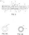
- a pump-out tube 8, that may be hermetically sealed, for example, of or including solder glass 9 is provided through a hole that passes from an interior surface of one of the glass substrates, e.g., substrate 3 in Fig. 3 , and through the glass substrate 3 and extending beyond the outside surface thereof.
- the pump-out tube 8 (before its tip is sealed/closed) is used in a process to evacuate the cavity 6 between the substrates 2, 3, such as, for example, by attaching a vacuum pump to the pump-out tube 8 and evacuating the cavity 6 to a low pressure, e.g., a pressure lower than atmospheric pressure.
- a pressure in the cavity 6 is, for example, preferably below about 10 -2 Torr, and more preferably below about 10 -3 Torr, and even more preferably below about 5x10 -4 Torr.
- the pump-out tube 8 may, for example, have a diameter or distance from about 0.1 to 1.0 mm, more preferably from about 0.3 to 0.7 mm, and even more preferably from about 0.5 mm.
- VIG window units using fused solder glass peripheral edge seals 4 may, for example, be manufactured by depositing glass frit, such as, for example, any of those referenced above, in a solution, around the periphery of one of the substrates, e.g., substrate 2. This glass frit ultimately forms the glass solder edge seal 4 after curing.
- a second substrate, e,.g., substrate 3 is brought down on substrate 2 so as to sandwich spacers/pillars 5 and the glass frit solution between the two substrates 2, 3.
- a pump-out tube 8 and vacuum apparatus may then be used to evacuate the cavity 6 formed between the substrates 2, 3 in the example manner described above to provide a low pressure (e.g., lower than atmospheric pressure) between the substrates 2, 3.
- the top or tip of the glass pump-out tube 8 may then be sealed by melting an exposed potion of the tube using a laser or the like.
- Sealing the pump-out tube 8 maintains the low pressure in the cavity 6. After the tube 8 has been sealed, the central portion of the tube 8 is still in fluid communication with the cavity 6, but the external atmosphere is not because the tip/top of the tube 8 has been sealed shut.
- an additional transparent glass substrate 15 is laminated over or above the substrates 2, 3 that define the cavity 6.
- the third glass substrate 15 may be the same size as substrate 3.
- the additional laminated glass substrate 15 may be adhered to the outer surface of one of the glass substrates, e.g., substrate 3, using a laminating film 14, that may be of, or include, a polymer based adhesive, such as, for example, PVB, or the like.
- a hole 11 is provided in the additional glass substrate 15 and the laminating film 14 to accommodate the exposed portion of the sealed pump-out tube 8 described above.
- the hole 11 is of a size to provide sufficient clearance about the pump-out tube 8 when the laminated substrate 15 and laminating film 14 are disposed over the substrate 3 of the VIG window unit 20. Due to manufacturing tolerances when creating the hole 11, there is a possibility that the holes in the substrate(s) and the protruding pump-out port 8 will not be concentrically or even substantially concentrically aligned. In addition, a glass edge of the access hole 11 formed in the laminated substrate 15 could have a rough edge. Both of these factors, e.g., poor registration of the holes in substrates 3 and 15 and pump-out port 8, and the rough edge around the access hole 11 in the laminated substrate 15, could contribute to an undesirable aesthetic appearance of the final laminated VIG unit.
- a protective cap 47 is provided over the pump-out tube 8 after the lamination process for providing the additional laminated glass substrate 15.
- the pump-out tube 8 must be exposed to a manufacturing process in which the laminating film 14 and additional laminated glass substrate 15 are placed over the exposed portions of the pump-out tube 8, thereby exposing the pump-out tube 8 to the potential for damage during the lamination process, such as, for example, and without limitation, by contact of the edges of the holes 11 in the laminating film 14 and/or additional laminated substrate 15 with the fragile glass pump-out tube 8.
- a process protection ring 16 is provided around the exposed pump-out tube 8 during lamination so as to surround the tube 8 when the unit in Fig. 3 is viewed from above.
- a process protection ring 16 may be adhered to the substrate 3 and surrounding the pump-out tube 8 using, for example, an adhesive tape, such as, for example, 3M VHB adhesive tape, prior to the lamination process that is used to laminate the additional glass substrate 15 to substrate 3.
- the process protection ring 16 may have a height substantially equal to a height of the exposed portion of the pump-out tube 8.
- the height of the process protection ring may have a height slightly less than that of the exposed portion of the pump-out tube 8, so long as the dimensions of the process protection ring are sufficient to provide adequate protection to the pump-out tube 8.
- a height of the process protection ring 16 is preferably not higher than a height of the pump-out tube 8 to avoid adding significant stack-up height that may affect the appearance of the laminated VIG unit 20.
- the ring 16 may be circular in shape as shown in Figs. 4A-4B , or alternatively may be oval shaped, substantially circular shaped, substantially square, and/or substantially rectangular shaped.
- FIGS. 4A and 4B bottom plan views of an example process protection ring 16 are shown.
- the process protection ring 16 may be generally circular in cross section and otherwise generally cylindrical. Of course, other suitable geometries may be used so long as adequate protection is provided to the pump-out tube 8 during the lamination process as mentioned above.
- FIG. 4B is a bottom plan view of an example process protection ring 16 showing an adhesive 17, such as, for example, 3M VHB adhesive tape, or the like, used to adhere the process protection ring 16 to the surface of a substrate, e.g., substrate 3, of the VIG unit 20 prior to the lamination process.
- an adhesive 17 such as, for example, 3M VHB adhesive tape, or the like
- a preferred height of the process protection ring 16 may be set to be less than or substantially equal to a height of the exposed portion of the pump-out tube 8, and should preferably be of sufficient height to provide protection to the exposed portions of the pump-out tube 8 during the lamination process. It is also noted that by providing a process protection ring 16 prior to lamination, the need for providing a cap during the lamination process is avoided in certain example instances. Thus, as discussed below, a single cap may be disposed over the holes 11 in the laminating film 14 and the laminated substrate 15 that were provided to accommodate the protruding portion of the pump-out tube 8.
- a protective cap is provided over the hole(s) 11 as discussed above, to provide further protection by covering the exposed pump-out tube 8, and to provide further aesthetic improvement by covering the holes 11 in the laminating film 14 and the additional laminates substrate 15 that were formed to accommodate the exposed pump-out port 8 during lamination, e.g., by covering any potential misalignment or non-concentric arrangement of the pump-out tube 8 and holes that may otherwise be visible.
- FIG. 5 a laminated VIG window unit 20 including the laminated substrate 15, laminating film 14, process protection ring 16 and protective cap 47 is illustrated in cross section.
- FIG. 5 is similar to FIG. 3 , but includes an illustration of the protective cap 47.
- the protective cap 47 is disposed over the holes (see 11 in Fig. 3 ) that accommodate the exposed portion of the pump-out tube 8 and the process protection ring 16 discussed above.
- the protective cap 47 may be adhered to the outer surface of the additional laminated glass substrate 15 by way of an adhesive tape 19, such as, for example, 3M VHB adhesive tape, or the like.
- the size of the protective cap 47 is preferably such that it provides complete coverage of the holes 11 and is of sufficiently low profile to provide further desirable aesthetic appearance of the laminated VIG unit 20.
- the protective cap 47 includes an inner cavity 21 having a diameter and depth sufficient to accompodate the pump-out tube 8, the process protection ring 16 and to completely cover the hole 11 in the laminated substrate 15.
- the surface area of the base portion of the cap should be sufficient to accommodate enough adhesive tape to provide a secure connection to the laminated substrate 15.
- the protective cap 47 may also optionally be provided with a positioning ridge 18 provided about a periphery of the side of the cap that faces the laminated glass substrate 15 of the generally circular protective cap 47 (e.g., see Figs. 5-6 ).
- the positioning ridge 18 may preferably engage or be located very close to an interior portion of the hole 11 in the laminated substrate 15 to provide additional protective strength for the protective cap, and further reduce the amount of movement of the protection cap once placed over the hole in the laminated substrate 15 (e.g., see Fig. 5 ).
- FIGS 6A and 6B are a bottom plan view and a cross sectional view, respectively, of example embodiments of the protective cap 47.
- the protective cap 47 may have a generally circular shape.
- the positioning ridge 18 generally conforms to this shape and is disposed in a peripheral region of the side of the protective cap 47 that engages the hole in the laminated substrate 15.
- an adhesive tape 19 such as, for example, 3M VHB adhesive tape, or the like, is shown.
- FIG. 6B a cross section of the protective cap 47 according to an example embodiment is illustrated.
- an optional positioning ridge 18 may also be provided with the protective cap 47 as described above.
- outer diameter D2 of the positioning ridge 18 may be such that it engages the hole formed in the laminated substrate 15, or is close to engaging the hole.
- An inner diameter D1 of the positioning ridge 18 may be such that it is sufficient to accommodate the process protection ring 16 and exposed portion of the pump-out tube 8 in a cavity 21 defined by a top of the protective cap 47 and the positioning ring 18.
- the protective cap 47 is illustrated having a generally circular shape, it will be understood that any suitable shape may be used.
- a generally polygonal exterior shape in combination with a generally circular positioning ridge 18 may be used. It will be understood that it is preferable that the positioning ridge 18 be of a shape to adequately engage an inner portion of the hole formed in the additional laminated substrate 15.
- the positioning ring 18 it is not necessary for the positioning ring 18 to be continuous, and it may be provided by a number of protrusions about a periphery of an interior cavity 21 of the protective cap 47, for example.
- the protective cap 47 may, for example, be made of or including metal, plastic, silicone, or some other suitable material.
- the coefficients of thermal expansion of the cap 47 and the glass substrates may match one another, for example, within about 25%, more preferably within about 20% and even more preferably in a range of about 10-20%.
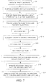
- FIG. 7 is a flowchart illustrating an example method for making a laminated VIG unit according to an example embodiment.
- a first substrate such as, for example, a substrate of or including glass is provided in step S1.
- Spacers or pillars such as those discussed above, are then provided on a first major surface of the first substrate and located at spaced apart positions sufficient to maintain spacing between the first substrate and a second substrate to be provided S3.
- a frit material such as, for example, those discussed above that provide the edge seal, is disposed (e.g., printed or otherwise applied) around peripheral edges of the first substrate.
- a second substrate such as, for example, a substrate of or including glass, is provided over the first substrate, sandwiching the pillars or spacers and frit material, thereby defining a cavity between the two substrates S7.
- the subassembly including the first and second substrates, spacers and frit material is then heated at a sufficient level to form a hermetic edge seal S9.
- the cavity defined between the two substrates is then evacuated to a suitable vacuum level, being lower than atmospheric pressure, by, using a pump-out tube S11.
- the cavity then may optionally be cleaned using a suitable process, such as, for example, plasma cleaning, such as, for example, and without limitation, as disclosed in U.S. Patent Application Serial No. 13/149,085, filed May 31, 2011 , and U.S. Patent No. 6,692,600 , S13.
- the pump-out tube may then be sealed S15 by any suitable means, such as, for example, and without limitation, melting using a laser, exposing the tube to other heat energy, or the like.
- a process protection tube of the type disclosed and described above is then disposed about the exposed and sealed pump out tube S17.
- the process protection tube may be affixed to the second substrate by, for example, and without limitation, an adhesive tape, such as, for example, 3M VHB adhesive tape.
- a laminating film and additional substrate are disposed over the second substrate, and include holes for accommodating the exposed sealed pump-out tube and process protection ring.
- the laminating film may, for example, be of or include a polymer based adhesive, such as, for example, PVB.
- the laminated VIG unit so formed has a number of substantially aligned holes that accommodate the exposed pump-out tube and surrounding process protection ring.
- a protective cap 47 is then provided to cover the holes and the exposed pump-out tube and process protection ring S21.
- a positioning ridge in the protective cap may be arranged to engage an interior surface of a hole in the laminated glass substrate.
Landscapes
- Engineering & Computer Science (AREA)
- Civil Engineering (AREA)
- Structural Engineering (AREA)
- Joining Of Glass To Other Materials (AREA)
- Securing Of Glass Panes Or The Like (AREA)
Priority Applications (1)
| Application Number | Priority Date | Filing Date | Title |
|---|---|---|---|
| PL13722637T PL2847409T3 (pl) | 2012-05-08 | 2013-04-29 | Zespół okienny z szybami zespolonymi próżniowo, obejmujący pierścień zabezpieczający i nasadkę rurki wypompowującej oraz sposób ich wytwarzania |
Applications Claiming Priority (2)
| Application Number | Priority Date | Filing Date | Title |
|---|---|---|---|
| US13/466,356 US9695628B2 (en) | 2012-05-08 | 2012-05-08 | Vacuum insulated glass (VIG) window unit including pump-out tube protection ring and/or cap and methods for making same |
| PCT/US2013/038575 WO2013169504A1 (en) | 2012-05-08 | 2013-04-29 | Vacuum insulated glass (vig) window unit including pump-out tube protection ring and/or cap and methods for making same |
Publications (2)
| Publication Number | Publication Date |
|---|---|
| EP2847409A1 EP2847409A1 (en) | 2015-03-18 |
| EP2847409B1 true EP2847409B1 (en) | 2019-12-11 |
Family
ID=48430942
Family Applications (1)
| Application Number | Title | Priority Date | Filing Date |
|---|---|---|---|
| EP13722637.9A Active EP2847409B1 (en) | 2012-05-08 | 2013-04-29 | Vacuum insulated glass window unit including pump-out tube protection ring and cap and method for making same |
Country Status (8)
| Country | Link |
|---|---|
| US (1) | US9695628B2 (pl) |
| EP (1) | EP2847409B1 (pl) |
| JP (1) | JP6270167B2 (pl) |
| CN (1) | CN104411908B (pl) |
| DK (1) | DK2847409T3 (pl) |
| ES (1) | ES2773483T3 (pl) |
| PL (1) | PL2847409T3 (pl) |
| WO (1) | WO2013169504A1 (pl) |
Families Citing this family (30)
| Publication number | Priority date | Publication date | Assignee | Title |
|---|---|---|---|---|
| WO2011153381A2 (en) | 2010-06-02 | 2011-12-08 | Eversealed Windows, Inc. | Multi-pane glass unit having seal with adhesive and hermetic coating layer |
| US8802203B2 (en) | 2011-02-22 | 2014-08-12 | Guardian Industries Corp. | Vanadium-based frit materials, and/or methods of making the same |
| US9309146B2 (en) | 2011-02-22 | 2016-04-12 | Guardian Industries Corp. | Vanadium-based frit materials, binders, and/or solvents and methods of making the same |
| US9290408B2 (en) | 2011-02-22 | 2016-03-22 | Guardian Industries Corp. | Vanadium-based frit materials, and/or methods of making the same |
| US9328512B2 (en) | 2011-05-05 | 2016-05-03 | Eversealed Windows, Inc. | Method and apparatus for an insulating glazing unit and compliant seal for an insulating glazing unit |
| EP3191416A4 (en) | 2013-10-18 | 2018-05-30 | Eversealed Windows, Inc. | Edge seal assemblies for hermetic insulating glass units and vacuum insulating glass units |
| US9675231B2 (en) | 2013-12-19 | 2017-06-13 | Whirlpool Corporation | Door assembly for a dishwasher |
| US9784027B2 (en) | 2013-12-31 | 2017-10-10 | Guardian Glass, LLC | Vacuum insulating glass (VIG) unit with metallic peripheral edge seal and/or methods of making the same |
| US10280680B2 (en) | 2013-12-31 | 2019-05-07 | Guardian Glass, LLC | Vacuum insulating glass (VIG) unit with pump-out port sealed using metal solder seal, and/or method of making the same |
| US10012019B2 (en) | 2013-12-31 | 2018-07-03 | Guardian Glass, LLC | Vacuum insulating glass (VIG) unit with metallic peripheral edge seal and/or methods of making the same |
| US9593527B2 (en) | 2014-02-04 | 2017-03-14 | Guardian Industries Corp. | Vacuum insulating glass (VIG) unit with lead-free dual-frit edge seals and/or methods of making the same |
| US9988302B2 (en) | 2014-02-04 | 2018-06-05 | Guardian Glass, LLC | Frits for use in vacuum insulating glass (VIG) units, and/or associated methods |
| JPWO2016009948A1 (ja) * | 2014-07-18 | 2017-05-25 | 旭硝子株式会社 | 真空複層ガラス |
| WO2016061839A1 (zh) * | 2014-10-20 | 2016-04-28 | 太阳真空玻璃有限公司 | 真空板材及其制造方法 |
| EP3317022B1 (en) | 2015-07-01 | 2021-08-25 | Guardian Glass, LLC | Vacuum insulating glass (vig) unit with metallic peripheral edge seal and/or methods of making the same |
| US10145005B2 (en) | 2015-08-19 | 2018-12-04 | Guardian Glass, LLC | Techniques for low temperature direct graphene growth on glass |
| WO2017028870A1 (en) * | 2015-08-20 | 2017-02-23 | Vkr Holding A/S | Evacuation head with ceramic heater for vig unit manufacture |
| US10683693B2 (en) * | 2016-07-06 | 2020-06-16 | Je Il PARK | Method for manufacturing vacuum insulation glass panel and device for closing sealing cap |
| JP2018188341A (ja) | 2017-05-10 | 2018-11-29 | 株式会社日立製作所 | 複層ガラス及びその製造方法 |
| KR102068648B1 (ko) | 2017-11-30 | 2020-01-22 | 엘지전자 주식회사 | 진공유리 및 그 제조방법 |
| PL3794204T3 (pl) * | 2018-05-14 | 2025-04-07 | Agc Glass Europe | Asymetryczna, bezpieczna, próżniowo izolowana szyba zespolona |
| JP7063740B2 (ja) * | 2018-06-18 | 2022-05-09 | 日本板硝子株式会社 | 真空ガラスパネル |
| WO2020043614A1 (en) | 2018-08-30 | 2020-03-05 | Vkr Holding A/S | Laminated vacuum insulated glass unit |
| JP7479118B2 (ja) * | 2018-10-12 | 2024-05-08 | 日本板硝子株式会社 | ガラスユニットの製造方法 |
| WO2020120440A1 (en) * | 2018-12-14 | 2020-06-18 | Agc Glass Europe | Laminated vacuum-insulated glazing assembly |
| US10900275B2 (en) * | 2019-01-04 | 2021-01-26 | Guardian Glass, LLC | Integrated tube for vacuum insulated glass (VIG) unit evacuation and hermetic sealing, VIG unit including integrated tube, and associated methods |
| US20220235601A1 (en) * | 2019-07-15 | 2022-07-28 | Annette Johncock KRISKO | Manufacturing of vacuum insulated glazing unit |
| EP4045749A1 (en) * | 2019-10-18 | 2022-08-24 | AGC Glass Europe | Fire resistant vacuum insulating glazing |
| CN111890890A (zh) * | 2020-08-07 | 2020-11-06 | 福耀玻璃工业集团股份有限公司 | 一种带有通孔的车窗玻璃 |
| US20250354431A1 (en) * | 2024-05-15 | 2025-11-20 | LuxWall, Inc. | Vacuum insulated panel with trough for getter |
Citations (1)
| Publication number | Priority date | Publication date | Assignee | Title |
|---|---|---|---|---|
| CN2564694Y (zh) * | 2002-07-26 | 2003-08-06 | 唐健正 | 真空玻璃抽气口保护罩 |
Family Cites Families (34)
| Publication number | Priority date | Publication date | Assignee | Title |
|---|---|---|---|---|
| US3837866A (en) | 1972-04-24 | 1974-09-24 | Corning Glass Works | Low melting vanadate glasses |
| JPS5446215A (en) | 1977-09-21 | 1979-04-12 | Hitachi Ltd | Sealing glass |
| GB8407465D0 (en) * | 1984-03-22 | 1984-05-02 | Rieter Ag Maschf | Length control in winding of threads |
| JPS6129035A (ja) | 1984-07-18 | 1986-02-08 | Nec Corp | 表示管およびその製造方法 |
| US4743302A (en) | 1986-06-06 | 1988-05-10 | Vlsi Packaging Materials, Inc. | Low melting glass composition |
| JPH0764588B2 (ja) | 1989-04-28 | 1995-07-12 | 日本電気硝子株式会社 | 被覆用ガラス組成物 |
| US5156894A (en) | 1989-08-02 | 1992-10-20 | Southwall Technologies, Inc. | High performance, thermally insulating multipane glazing structure |
| US5544465A (en) | 1989-08-02 | 1996-08-13 | Southwall Technologies, Inc. | Thermally insulating multipane glazing struture |
| US5657607A (en) | 1989-08-23 | 1997-08-19 | University Of Sydney | Thermally insulating glass panel and method of construction |
| US5308662A (en) | 1991-07-16 | 1994-05-03 | Southwall Technologies Inc. | Window construction with UV protecting treatment |
| US5188990A (en) | 1991-11-21 | 1993-02-23 | Vlsi Packaging Materials | Low temperature sealing glass compositions |
| ATE194205T1 (de) | 1992-01-31 | 2000-07-15 | Univ Sydney | Verbesserungen für thermisch isolierende glasscheiben |
| CN1078659C (zh) | 1993-06-30 | 2002-01-30 | 悉尼大学 | 制造真空玻璃窗的方法 |
| US5336644A (en) | 1993-07-09 | 1994-08-09 | Johnson Matthey Inc. | Sealing glass compositions |
| US5534469A (en) | 1995-09-12 | 1996-07-09 | Nippon Electric Glass Co., Ltd. | Low temperature non-crystallizing sealing glass |
| MX9605168A (es) | 1995-11-02 | 1997-08-30 | Guardian Industries | Sistema de recubrimiento con vidrio de baja emisividad, durable, de alto funcionamiento, neutro, unidades de vidrio aislante elaboradas a partir del mismo, y metodos para la fabricacion de los mismos. |
| US5964630A (en) * | 1996-12-23 | 1999-10-12 | Candescent Technologies Corporation | Method of increasing resistance of flat-panel device to bending, and associated getter-containing flat-panel device |
| JPH11278877A (ja) | 1998-03-31 | 1999-10-12 | Central Glass Co Ltd | 低圧空間を有する複層ガラスおよびその製造方法 |
| JP2000203892A (ja) | 1999-01-18 | 2000-07-25 | Nippon Sheet Glass Co Ltd | ガラスパネル |
| JP4274639B2 (ja) | 1999-08-20 | 2009-06-10 | 日本板硝子株式会社 | ガラスパネル |
| JP4540224B2 (ja) | 2000-01-07 | 2010-09-08 | 日本電気硝子株式会社 | タブレット一体型ガラス管 |
| US6692600B2 (en) | 2001-09-14 | 2004-02-17 | Guardian Industries Corp. | VIG evacuation with plasma excitation |
| JP4049607B2 (ja) | 2002-04-11 | 2008-02-20 | 日本板硝子株式会社 | ガラスパネルの製造方法とその方法で製造されたガラスパネル |
| US6632491B1 (en) | 2002-05-21 | 2003-10-14 | Guardian Industries Corp. | IG window unit and method of making the same |
| JP4299021B2 (ja) | 2003-02-19 | 2009-07-22 | ヤマト電子株式会社 | 封着加工材及び封着加工用ペースト |
| AU2003900862A0 (en) * | 2003-02-26 | 2003-03-13 | The University Of Sydney | Improved sealing arrangement for use in evacuating a glass chamber |
| US7294402B2 (en) | 2004-03-05 | 2007-11-13 | Guardian Industries Corp. | Coated article with absorbing layer |
| CN2835403Y (zh) | 2005-07-22 | 2006-11-08 | 唐健正 | 安全结构的真空夹胶玻璃 |
| US8377524B2 (en) | 2005-12-27 | 2013-02-19 | Guardian Industries Corp. | High R-value window unit |
| CN101059056A (zh) * | 2006-04-18 | 2007-10-24 | 于通生 | 一种高强度真空玻璃 |
| US7851034B2 (en) | 2007-12-03 | 2010-12-14 | Guardian Industries Corp. | Embedded vacuum insulating glass unit, and/or method of making the same |
| US8137494B2 (en) | 2007-12-14 | 2012-03-20 | Guardian Industries Corp. | Vacuum insulating glass unit with large pump-out port, and/or method of making the same |
| US8227055B2 (en) | 2009-05-01 | 2012-07-24 | Guardian Industries Corp. | Vacuum insulating glass unit including infrared meltable glass frit, and/or method of making the same |
| US8202587B2 (en) | 2009-05-01 | 2012-06-19 | Guardian Industries Corp. | Edge profiles for vacuum insulated glass (VIG) units, and/or VIG unit including the same |
-
2012
- 2012-05-08 US US13/466,356 patent/US9695628B2/en active Active
-
2013
- 2013-04-29 JP JP2015511505A patent/JP6270167B2/ja active Active
- 2013-04-29 EP EP13722637.9A patent/EP2847409B1/en active Active
- 2013-04-29 CN CN201380035472.4A patent/CN104411908B/zh not_active Expired - Fee Related
- 2013-04-29 WO PCT/US2013/038575 patent/WO2013169504A1/en not_active Ceased
- 2013-04-29 PL PL13722637T patent/PL2847409T3/pl unknown
- 2013-04-29 DK DK13722637.9T patent/DK2847409T3/da active
- 2013-04-29 ES ES13722637T patent/ES2773483T3/es active Active
Patent Citations (1)
| Publication number | Priority date | Publication date | Assignee | Title |
|---|---|---|---|---|
| CN2564694Y (zh) * | 2002-07-26 | 2003-08-06 | 唐健正 | 真空玻璃抽气口保护罩 |
Also Published As
| Publication number | Publication date |
|---|---|
| US9695628B2 (en) | 2017-07-04 |
| WO2013169504A1 (en) | 2013-11-14 |
| PL2847409T3 (pl) | 2020-06-01 |
| CN104411908B (zh) | 2017-07-11 |
| JP6270167B2 (ja) | 2018-01-31 |
| US20130302542A1 (en) | 2013-11-14 |
| ES2773483T3 (es) | 2020-07-13 |
| JP2015523300A (ja) | 2015-08-13 |
| CN104411908A (zh) | 2015-03-11 |
| DK2847409T3 (da) | 2020-03-02 |
| EP2847409A1 (en) | 2015-03-18 |
Similar Documents
| Publication | Publication Date | Title |
|---|---|---|
| EP2847409B1 (en) | Vacuum insulated glass window unit including pump-out tube protection ring and cap and method for making same | |
| EP3575273B9 (en) | Preparation process for vacuum glass | |
| US8683775B1 (en) | Spacer system for installing vacuum insulated glass (VIG) window unit in window frame designed to accommodate thicker IG window unit | |
| JP6479172B2 (ja) | 絶縁グレージングユニットに用いられるスペーサ、当該スペーサを有する絶縁グレージングユニット、当該スペーサの製造方法及び使用 | |
| US20130074445A1 (en) | Vacuum insulating glass (vig) unit pump-out tube protecting techniques, and/or vig units incorporating the same | |
| EP3705675B1 (en) | A kit-of-parts for a spacer system for installing vacuum insulated glass (vig) window unit in window frame designed to accommodate thicker ig window unit | |
| EP2855816B1 (en) | Method for making a vacuum insulated glass (vig) window unit with reduced seal height variation | |
| EP3438063B1 (en) | Glass panel unit and glass window | |
| JP5870486B2 (ja) | 複層ガラス窓の組立方法 | |
| CN105074113A (zh) | 具有真空绝缘玻璃(vig)单元和含有真空绝缘结构的窗 | |
| JP5783438B2 (ja) | 複層ガラス窓及び複層ガラス窓の組立方法 | |
| EP3987143B1 (en) | Flanged tube for vacuum insulated glass (vig) unit evacuation and hermetic sealing, vig unit including flanged tube, and associated methods | |
| EP3170799B1 (en) | Vacuum multi-layer glass | |
| KR20130022535A (ko) | 진공유리 및 그 제조방법 | |
| JP2018012637A (ja) | 複層ガラスの製造方法 | |
| CN112839914A (zh) | 玻璃单元 | |
| JP2015004167A (ja) | 複層ガラス窓及び複層ガラス窓の組立方法 | |
| EP2710309A2 (en) | Roof-mounted water heater | |
| EP3604245B1 (en) | Method for manufacturing glass panel unit and method for manufacturing glass window | |
| JP2018087095A (ja) | 複層ガラス、および複層ガラスの製造方法 | |
| JPH09278498A (ja) | 複層ガラスと複層ガラス支持構造 |
Legal Events
| Date | Code | Title | Description |
|---|---|---|---|
| PUAI | Public reference made under article 153(3) epc to a published international application that has entered the european phase |
Free format text: ORIGINAL CODE: 0009012 |
|
| 17P | Request for examination filed |
Effective date: 20141208 |
|
| AK | Designated contracting states |
Kind code of ref document: A1 Designated state(s): AL AT BE BG CH CY CZ DE DK EE ES FI FR GB GR HR HU IE IS IT LI LT LU LV MC MK MT NL NO PL PT RO RS SE SI SK SM TR |
|
| AX | Request for extension of the european patent |
Extension state: BA ME |
|
| DAX | Request for extension of the european patent (deleted) | ||
| STAA | Information on the status of an ep patent application or granted ep patent |
Free format text: STATUS: EXAMINATION IS IN PROGRESS |
|
| 17Q | First examination report despatched |
Effective date: 20170523 |
|
| RAP1 | Party data changed (applicant data changed or rights of an application transferred) |
Owner name: GUARDIAN GLASS, LLC |
|
| GRAP | Despatch of communication of intention to grant a patent |
Free format text: ORIGINAL CODE: EPIDOSNIGR1 |
|
| STAA | Information on the status of an ep patent application or granted ep patent |
Free format text: STATUS: GRANT OF PATENT IS INTENDED |
|
| INTG | Intention to grant announced |
Effective date: 20190718 |
|
| GRAS | Grant fee paid |
Free format text: ORIGINAL CODE: EPIDOSNIGR3 |
|
| GRAA | (expected) grant |
Free format text: ORIGINAL CODE: 0009210 |
|
| STAA | Information on the status of an ep patent application or granted ep patent |
Free format text: STATUS: THE PATENT HAS BEEN GRANTED |
|
| AK | Designated contracting states |
Kind code of ref document: B1 Designated state(s): AL AT BE BG CH CY CZ DE DK EE ES FI FR GB GR HR HU IE IS IT LI LT LU LV MC MK MT NL NO PL PT RO RS SE SI SK SM TR |
|
| REG | Reference to a national code |
Ref country code: GB Ref legal event code: FG4D |
|
| REG | Reference to a national code |
Ref country code: CH Ref legal event code: EP |
|
| REG | Reference to a national code |
Ref country code: AT Ref legal event code: REF Ref document number: 1212345 Country of ref document: AT Kind code of ref document: T Effective date: 20191215 |
|
| REG | Reference to a national code |
Ref country code: DE Ref legal event code: R096 Ref document number: 602013063864 Country of ref document: DE |
|
| REG | Reference to a national code |
Ref country code: IE Ref legal event code: FG4D |
|
| REG | Reference to a national code |
Ref country code: DK Ref legal event code: T3 Effective date: 20200225 |
|
| REG | Reference to a national code |
Ref country code: NL Ref legal event code: MP Effective date: 20191211 |
|
| REG | Reference to a national code |
Ref country code: LT Ref legal event code: MG4D |
|
| PG25 | Lapsed in a contracting state [announced via postgrant information from national office to epo] |
Ref country code: GR Free format text: LAPSE BECAUSE OF FAILURE TO SUBMIT A TRANSLATION OF THE DESCRIPTION OR TO PAY THE FEE WITHIN THE PRESCRIBED TIME-LIMIT Effective date: 20200312 Ref country code: NO Free format text: LAPSE BECAUSE OF FAILURE TO SUBMIT A TRANSLATION OF THE DESCRIPTION OR TO PAY THE FEE WITHIN THE PRESCRIBED TIME-LIMIT Effective date: 20200311 Ref country code: SE Free format text: LAPSE BECAUSE OF FAILURE TO SUBMIT A TRANSLATION OF THE DESCRIPTION OR TO PAY THE FEE WITHIN THE PRESCRIBED TIME-LIMIT Effective date: 20191211 Ref country code: FI Free format text: LAPSE BECAUSE OF FAILURE TO SUBMIT A TRANSLATION OF THE DESCRIPTION OR TO PAY THE FEE WITHIN THE PRESCRIBED TIME-LIMIT Effective date: 20191211 Ref country code: BG Free format text: LAPSE BECAUSE OF FAILURE TO SUBMIT A TRANSLATION OF THE DESCRIPTION OR TO PAY THE FEE WITHIN THE PRESCRIBED TIME-LIMIT Effective date: 20200311 Ref country code: LV Free format text: LAPSE BECAUSE OF FAILURE TO SUBMIT A TRANSLATION OF THE DESCRIPTION OR TO PAY THE FEE WITHIN THE PRESCRIBED TIME-LIMIT Effective date: 20191211 Ref country code: LT Free format text: LAPSE BECAUSE OF FAILURE TO SUBMIT A TRANSLATION OF THE DESCRIPTION OR TO PAY THE FEE WITHIN THE PRESCRIBED TIME-LIMIT Effective date: 20191211 |
|
| PG25 | Lapsed in a contracting state [announced via postgrant information from national office to epo] |
Ref country code: HR Free format text: LAPSE BECAUSE OF FAILURE TO SUBMIT A TRANSLATION OF THE DESCRIPTION OR TO PAY THE FEE WITHIN THE PRESCRIBED TIME-LIMIT Effective date: 20191211 Ref country code: RS Free format text: LAPSE BECAUSE OF FAILURE TO SUBMIT A TRANSLATION OF THE DESCRIPTION OR TO PAY THE FEE WITHIN THE PRESCRIBED TIME-LIMIT Effective date: 20191211 |
|
| PG25 | Lapsed in a contracting state [announced via postgrant information from national office to epo] |
Ref country code: AL Free format text: LAPSE BECAUSE OF FAILURE TO SUBMIT A TRANSLATION OF THE DESCRIPTION OR TO PAY THE FEE WITHIN THE PRESCRIBED TIME-LIMIT Effective date: 20191211 |
|
| REG | Reference to a national code |
Ref country code: ES Ref legal event code: FG2A Ref document number: 2773483 Country of ref document: ES Kind code of ref document: T3 Effective date: 20200713 |
|
| PG25 | Lapsed in a contracting state [announced via postgrant information from national office to epo] |
Ref country code: EE Free format text: LAPSE BECAUSE OF FAILURE TO SUBMIT A TRANSLATION OF THE DESCRIPTION OR TO PAY THE FEE WITHIN THE PRESCRIBED TIME-LIMIT Effective date: 20191211 Ref country code: NL Free format text: LAPSE BECAUSE OF FAILURE TO SUBMIT A TRANSLATION OF THE DESCRIPTION OR TO PAY THE FEE WITHIN THE PRESCRIBED TIME-LIMIT Effective date: 20191211 Ref country code: CZ Free format text: LAPSE BECAUSE OF FAILURE TO SUBMIT A TRANSLATION OF THE DESCRIPTION OR TO PAY THE FEE WITHIN THE PRESCRIBED TIME-LIMIT Effective date: 20191211 Ref country code: RO Free format text: LAPSE BECAUSE OF FAILURE TO SUBMIT A TRANSLATION OF THE DESCRIPTION OR TO PAY THE FEE WITHIN THE PRESCRIBED TIME-LIMIT Effective date: 20191211 Ref country code: PT Free format text: LAPSE BECAUSE OF FAILURE TO SUBMIT A TRANSLATION OF THE DESCRIPTION OR TO PAY THE FEE WITHIN THE PRESCRIBED TIME-LIMIT Effective date: 20200506 |
|
| PG25 | Lapsed in a contracting state [announced via postgrant information from national office to epo] |
Ref country code: SM Free format text: LAPSE BECAUSE OF FAILURE TO SUBMIT A TRANSLATION OF THE DESCRIPTION OR TO PAY THE FEE WITHIN THE PRESCRIBED TIME-LIMIT Effective date: 20191211 Ref country code: IS Free format text: LAPSE BECAUSE OF FAILURE TO SUBMIT A TRANSLATION OF THE DESCRIPTION OR TO PAY THE FEE WITHIN THE PRESCRIBED TIME-LIMIT Effective date: 20200411 Ref country code: SK Free format text: LAPSE BECAUSE OF FAILURE TO SUBMIT A TRANSLATION OF THE DESCRIPTION OR TO PAY THE FEE WITHIN THE PRESCRIBED TIME-LIMIT Effective date: 20191211 |
|
| REG | Reference to a national code |
Ref country code: DE Ref legal event code: R097 Ref document number: 602013063864 Country of ref document: DE |
|
| REG | Reference to a national code |
Ref country code: AT Ref legal event code: MK05 Ref document number: 1212345 Country of ref document: AT Kind code of ref document: T Effective date: 20191211 |
|
| PLBE | No opposition filed within time limit |
Free format text: ORIGINAL CODE: 0009261 |
|
| STAA | Information on the status of an ep patent application or granted ep patent |
Free format text: STATUS: NO OPPOSITION FILED WITHIN TIME LIMIT |
|
| 26N | No opposition filed |
Effective date: 20200914 |
|
| PG25 | Lapsed in a contracting state [announced via postgrant information from national office to epo] |
Ref country code: AT Free format text: LAPSE BECAUSE OF FAILURE TO SUBMIT A TRANSLATION OF THE DESCRIPTION OR TO PAY THE FEE WITHIN THE PRESCRIBED TIME-LIMIT Effective date: 20191211 Ref country code: SI Free format text: LAPSE BECAUSE OF FAILURE TO SUBMIT A TRANSLATION OF THE DESCRIPTION OR TO PAY THE FEE WITHIN THE PRESCRIBED TIME-LIMIT Effective date: 20191211 Ref country code: MC Free format text: LAPSE BECAUSE OF FAILURE TO SUBMIT A TRANSLATION OF THE DESCRIPTION OR TO PAY THE FEE WITHIN THE PRESCRIBED TIME-LIMIT Effective date: 20191211 |
|
| REG | Reference to a national code |
Ref country code: CH Ref legal event code: PL |
|
| PG25 | Lapsed in a contracting state [announced via postgrant information from national office to epo] |
Ref country code: LU Free format text: LAPSE BECAUSE OF NON-PAYMENT OF DUE FEES Effective date: 20200429 Ref country code: CH Free format text: LAPSE BECAUSE OF NON-PAYMENT OF DUE FEES Effective date: 20200430 Ref country code: LI Free format text: LAPSE BECAUSE OF NON-PAYMENT OF DUE FEES Effective date: 20200430 |
|
| REG | Reference to a national code |
Ref country code: BE Ref legal event code: MM Effective date: 20200430 |
|
| PG25 | Lapsed in a contracting state [announced via postgrant information from national office to epo] |
Ref country code: BE Free format text: LAPSE BECAUSE OF NON-PAYMENT OF DUE FEES Effective date: 20200430 |
|
| PG25 | Lapsed in a contracting state [announced via postgrant information from national office to epo] |
Ref country code: IE Free format text: LAPSE BECAUSE OF NON-PAYMENT OF DUE FEES Effective date: 20200429 |
|
| PG25 | Lapsed in a contracting state [announced via postgrant information from national office to epo] |
Ref country code: TR Free format text: LAPSE BECAUSE OF FAILURE TO SUBMIT A TRANSLATION OF THE DESCRIPTION OR TO PAY THE FEE WITHIN THE PRESCRIBED TIME-LIMIT Effective date: 20191211 Ref country code: MT Free format text: LAPSE BECAUSE OF FAILURE TO SUBMIT A TRANSLATION OF THE DESCRIPTION OR TO PAY THE FEE WITHIN THE PRESCRIBED TIME-LIMIT Effective date: 20191211 Ref country code: CY Free format text: LAPSE BECAUSE OF FAILURE TO SUBMIT A TRANSLATION OF THE DESCRIPTION OR TO PAY THE FEE WITHIN THE PRESCRIBED TIME-LIMIT Effective date: 20191211 |
|
| PG25 | Lapsed in a contracting state [announced via postgrant information from national office to epo] |
Ref country code: MK Free format text: LAPSE BECAUSE OF FAILURE TO SUBMIT A TRANSLATION OF THE DESCRIPTION OR TO PAY THE FEE WITHIN THE PRESCRIBED TIME-LIMIT Effective date: 20191211 |
|
| PGFP | Annual fee paid to national office [announced via postgrant information from national office to epo] |
Ref country code: FR Payment date: 20250310 Year of fee payment: 13 Ref country code: PL Payment date: 20250314 Year of fee payment: 13 |
|
| PGFP | Annual fee paid to national office [announced via postgrant information from national office to epo] |
Ref country code: IT Payment date: 20250320 Year of fee payment: 13 Ref country code: GB Payment date: 20250306 Year of fee payment: 13 |
|
| PGFP | Annual fee paid to national office [announced via postgrant information from national office to epo] |
Ref country code: DE Payment date: 20250305 Year of fee payment: 13 |
|
| PGFP | Annual fee paid to national office [announced via postgrant information from national office to epo] |
Ref country code: DK Payment date: 20250411 Year of fee payment: 13 Ref country code: ES Payment date: 20250506 Year of fee payment: 13 |