EP2843149A1 - Lucarne avec mécanisme d'ouverture - Google Patents
Lucarne avec mécanisme d'ouverture Download PDFInfo
- Publication number
- EP2843149A1 EP2843149A1 EP13182686.9A EP13182686A EP2843149A1 EP 2843149 A1 EP2843149 A1 EP 2843149A1 EP 13182686 A EP13182686 A EP 13182686A EP 2843149 A1 EP2843149 A1 EP 2843149A1
- Authority
- EP
- European Patent Office
- Prior art keywords
- window
- sash
- roof
- lever arm
- frame
- Prior art date
- Legal status (The legal status is an assumption and is not a legal conclusion. Google has not performed a legal analysis and makes no representation as to the accuracy of the status listed.)
- Granted
Links
- 230000007246 mechanism Effects 0.000 title claims abstract description 64
- 238000009434 installation Methods 0.000 claims abstract description 8
- 230000033001 locomotion Effects 0.000 claims description 18
- 241000282346 Meles meles Species 0.000 description 6
- 239000005357 flat glass Substances 0.000 description 5
- 238000010276 construction Methods 0.000 description 4
- 238000013459 approach Methods 0.000 description 3
- 230000005540 biological transmission Effects 0.000 description 3
- 239000011521 glass Substances 0.000 description 3
- 230000005484 gravity Effects 0.000 description 3
- 239000011295 pitch Substances 0.000 description 3
- 229910000831 Steel Inorganic materials 0.000 description 1
- 238000004140 cleaning Methods 0.000 description 1
- 238000013016 damping Methods 0.000 description 1
- 238000010586 diagram Methods 0.000 description 1
- 230000003670 easy-to-clean Effects 0.000 description 1
- 230000000694 effects Effects 0.000 description 1
- 238000009413 insulation Methods 0.000 description 1
- 239000002346 layers by function Substances 0.000 description 1
- 238000001556 precipitation Methods 0.000 description 1
- 238000007789 sealing Methods 0.000 description 1
- 239000010959 steel Substances 0.000 description 1
- XLYOFNOQVPJJNP-UHFFFAOYSA-N water Substances O XLYOFNOQVPJJNP-UHFFFAOYSA-N 0.000 description 1
Images


Classifications
-
- E—FIXED CONSTRUCTIONS
- E04—BUILDING
- E04D—ROOF COVERINGS; SKY-LIGHTS; GUTTERS; ROOF-WORKING TOOLS
- E04D13/00—Special arrangements or devices in connection with roof coverings; Protection against birds; Roof drainage; Sky-lights
- E04D13/03—Sky-lights; Domes; Ventilating sky-lights
- E04D13/035—Sky-lights; Domes; Ventilating sky-lights characterised by having movable parts
- E04D13/0358—Sky-lights; Domes; Ventilating sky-lights characterised by having movable parts the parts moving, in their own plane, e.g. rolling or sliding, or moving in parallel planes with or without an additional movement, e.g. both pivoting and rolling or sliding
-
- E—FIXED CONSTRUCTIONS
- E05—LOCKS; KEYS; WINDOW OR DOOR FITTINGS; SAFES
- E05D—HINGES OR SUSPENSION DEVICES FOR DOORS, WINDOWS OR WINGS
- E05D15/00—Suspension arrangements for wings
- E05D15/40—Suspension arrangements for wings supported on arms movable in vertical planes
- E05D15/46—Suspension arrangements for wings supported on arms movable in vertical planes with two pairs of pivoted arms
-
- E—FIXED CONSTRUCTIONS
- E05—LOCKS; KEYS; WINDOW OR DOOR FITTINGS; SAFES
- E05Y—INDEXING SCHEME RELATING TO HINGES OR OTHER SUSPENSION DEVICES FOR DOORS, WINDOWS OR WINGS AND DEVICES FOR MOVING WINGS INTO OPEN OR CLOSED POSITION, CHECKS FOR WINGS AND WING FITTINGS NOT OTHERWISE PROVIDED FOR, CONCERNED WITH THE FUNCTIONING OF THE WING
- E05Y2900/00—Application of doors, windows, wings or fittings thereof
- E05Y2900/10—Application of doors, windows, wings or fittings thereof for buildings or parts thereof
- E05Y2900/13—Application of doors, windows, wings or fittings thereof for buildings or parts thereof characterised by the type of wing
- E05Y2900/148—Windows
- E05Y2900/152—Roof windows
- E05Y2900/154—Skylights
Definitions
- the invention relates to a roof window with an opening mechanism for the window sash.
- the window sash is rotated via an arranged at the top of the window axis of rotation.
- the window sash must be opened against gravity unlike normal windows. Therefore, the casements of these skylights are typically supported by hydraulic springs to facilitate opening and secure the casement in the open position.
- this mechanism has a number of disadvantages. First, it is difficult to get to the outside of the sash to clean it. Second, the support mechanisms for the sash must be very robust and thus heavy and expensive to be designed to withstand even high wind speeds in the open state, as the open sash provides a high attack surface for the wind. This mechanism can not be used for any size roof windows, as correspondingly long supports for the roof window still have to be provided in the roof. This opening mechanism thus limits the size of skylights.
- Lammellen that cover the roof window opening by a plurality of juxtaposed smaller window sash.
- the individual window sashes can be opened by a rotation about an axis at the top.
- the attack surface for wind is substantially reduced and the much smaller areas of the casement rear sides are much more accessible from the inside.
- these skylights have the disadvantage that the view through the skylight window is disturbed by the window both in the closed and in the open window due to the large number of casements and their respective spars. Therefore, such louvre windows are mainly used in glass roofs, where the view in the area of the opening roof windows is not so important.
- WO9119070 discloses a solution to this problem.
- the skylight is divided into a fixed window glass and a mobile casement.
- the mobile window sash is mounted in a rail that moves the sash out of the closed window level and then slides over the fixed window glass. This allows only half of the roof window to open. At the same time it is almost impossible to clean the outside of the fixed window glass.
- the roof window has a window frame, a window sash and an opening mechanism.
- the window frame is designed for installation in a building roof.
- the opening mechanism for the Window sash can be brought into an open state and a closed state.
- the opening mechanism is configured such that the window sash is movable from the closed state to the open state, wherein the sash is arranged in a closed state in a first plane and in the open state in a second plane parallel to the first plane.
- the invention is also achieved by a roof with such a roof window.
- the opening from a first level to a second level parallel thereto allows the skylight to be flush mounted and still bring the sash into an open position which, due to its parallelism to the closed position and thus to the roof surface, provides little wind contact area.
- the sash can be designed more easily, since it is no longer exposed to such high forces.
- the cleaning of the outer window surface is very easy, as it is directly adjacent to the window area with the window open.
- the opening mechanism includes a first lever arm between a first side of the sash and a first side of the sash and at least one second lever between a second side of the sash and a second side of the sash, the lever arms being rotatable on the sash and sash are stored, wherein the opening mechanism is adapted to move the window sash by a rotation of the lever arms laterally out of the window frame.
- This arrangement is particularly advantageous, since it is possible with this mechanism, by only a movement with only one degree of freedom, namely the rotation of at least one of the levers about the bearing axis, is possible to lift the sash out of the plane of the roof and parallel to the Place the lock on the side of the roof. This allows even flush with the roof built-in window a simple opening mechanism that releases the skylight and makes the outside of the window sash in the open state easily accessible.
- the opening mechanism is configured such that the opening of the sash reached by the rotation of the lever arms is such that the sash releases more than 70% of the sash window opening area of the sash window in the open state when closed by the sash.
- the opening mechanism is configured to move the window sash in a circular path from the closed state to the open state, wherein the window sash first moves away from the first plane during the opening operation and then approaches the first plane again.
- the opening mechanism is configured to rotate the first lever arm and / or the second lever arm between the closed state and the open state by an angle of at least 140 °.
- a rotation angle is possible, which allows to deposit the lever arms next to the window opening on a plane which corresponds approximately to the first level. If the roof window is mounted in the roof, this level corresponds to the roof surface.
- the first in the direct line between the pivot points of the lever on a recess for the window frame which is formed so that in the open state of the opening mechanism, the recess of the first and third lever arm releases the window frame.
- the laying down of the first lever arm on the roof surface absorbs the gravity acting on the opening mechanism, which reduces the wear of the opening mechanism.
- the first lever arm has a short portion and a long portion, wherein the long portion is disposed in the open state generally parallel to the first plane and the short portion is formed in the open state, the long portion with the storage of first lever arm in the window frame to connect.
- the length of the first lever arm and the second lever arm basically corresponds to half of a length of the first or second side of the window sash. So it is possible to move the window sash completely or at least almost completely out of the opening of the roof window.
- the first lever arm is attached at a first end to the opening side end of the first side of the window frame and an opposite second end in the center of the first side of the sash
- the second lever arm is connected to a first end in the window sash Attached to the middle of the second side of the window frame and at an opposite second end to the opposite side of the opening side of the second side of the window sash. So it is possible to move the window sash completely or at least almost completely out of the opening of the roof window.
- the opening mechanism comprises a third lever arm and / or a fourth lever arm, wherein the third lever arm between the first side of the sash and the first side of the window frame is arranged mirror-symmetrically to the second lever arm, and / or the fourth lever arm between the second Side of the sash and the second side of the window frame is arranged mirror-symmetrically to the first lever arm.
- a parallelogram guide of the window sash allows a simple and stable guidance of the sash on a circular path from a first plane to a second plane.
- the first lever arm is arranged in the direction of the axis of rotation laterally offset from the third lever arm and / or the second lever arm in the direction of Rotary axis is arranged laterally offset from the fourth lever arm. Only by such an arrangement, it is possible to store the pivot point of the first lever arm in the middle of the first side of the sash and at the same time to store the third lever arm in the middle of the first side of the window frame.
- the sash in the open state of the opening mechanism, lies on a longitudinal side of the first lever arm. This additionally stabilizes the window sash in the open state.
- the longitudinal side of the first lever arm or the window sash in at least a portion of the support surface on a damping element.
- the window sash lies on the longitudinal side of the first lever arm so that the sash remains in this position.
- the axes of rotation of the lever arms are parallel to each other.
- the window frame has an inner frame and an outer frame, and the lever arms are disposed between the inner frame and the outer frame. In one embodiment, the lever arms are mounted on the inner frame.
- At least one of the lever arms is driven by a motor to move the sash from the closed condition to the open condition.
- the axis of rotation of the at least one motor-driven lever arm in the window frame is rotatable by motor-driven power transmission means, the motor and the lever arm having different axes of rotation.
- the axis of rotation of the motor and the axis of rotation of the at least one motor-driven lever arm are arranged in parallel in the window frame and frictionally coupled with a toothed belt as a force transmission means.
- the window frame has an inner frame and an outer frame, and the force transmission means are non-positively coupled between the inner frame and the at least one motor-driven lever arm with the axis of rotation of the at least one motor-driven lever arm.
- the window frame has an inner frame and an outer frame, and the motor is fixed to the inner frame.
- the roof window on spring means which supports the lifting movement of the semi-circular movement of the sash and the lowering of the semi-circular movement of the sash brakes.
- the angle of the spring means is adjustable, below which the support effect of the spring means passes into a braking action.
- the spring means can be adapted to different roof pitches.
- the casement is in the open state on the roof surface. This has the advantage that the opening mechanism is force-free in the open state. This reduces the wear of the opening mechanism.
- the first side and the second side of the sash and / or the window frame are shorter than the other two sides of the sash and / or the window frame.
- the sash opens in the direction of the shorter side, causing the sash to move less to the side, resulting in shorter lever arms, resulting in a lower force for rotating the lever arms.
- the roof windows are usually longer in the direction of the inclination of the roof, it is particularly advantageous to open the roof window transversely to a slope of the roof. This has the additional advantage that the outside of the window sash is in the open state along the longitudinal side of the roof window next to the opening of the roof window.
- a cleaner has to clean the Lean window area only over the width of the roof window from the opening and not over the length of the roof window.
- the opening mechanism is configured such that, in the open state, the sash releases more than 70% of the area of the sash window opening of the sash window covered in the closed state by the window sash.
- the opening mechanism is configured so that the sash does not require sash guides mounted outside the sash to move from the closed condition to the open condition.
- the movement from the roof window is achieved only by the rotation of the lever arms.
- a translatory movement in a rail is not necessary.
- the opening mechanism brings the sash from the first level to a second level, the sash can be opened laterally even with flush arrangement of the window, without requiring a change of the roof by guide rails or openings in the roof next to the window opening.
- the window sash closes in the closed state, the opening formed by the window frame.
- the roof window has only one window sash.
- the sash has an inside and an outside, wherein the outside of the sash defines the first plane in the closed state and the outside of the sash defines the second plane in the open state.
- the first plane is spaced a maximum of 20 cm from the inside of the sash in the open state.
- the first plane is spaced at least the thickness of the sash from the second plane.
- the window sash in the open state releases the opening formed by the window frame completely.
- the first lever arm has a short section and a long section.
- the short section has an angle between 40 ° and 140 ° with the long section.
- the length of the short section corresponds at least to the distance of the pivot point of the first lever arm in the window sash and a plane formed by the outer support surface of the window frame.
- the length of the long portion of the first and second lever arms or the length of the first and second lever arms is one-half the length of the first or second side of the sash.
- the opening mechanism comprises a lifting mechanism for lifting the window sash and a pushing mechanism with a telescopic mechanism for laterally displacing the sash.
- the thrust mechanism in the window sash on a first upper guide and a second upper guide wherein the first upper guide is mounted longitudinally displaceably on an upper guide a first telescopic rail, the second upper guide is mounted longitudinally displaceably on an upper guide a second telescopic rail and the pusher mechanism in the window frame comprises a first lower guide and a second lower guide, the first telescopic rail being longitudinally displaceable in a first lower guide, the second telescopic rail being longitudinally displaceably mounted in a second lower guide, and the first and second lower guides positively connected to the lifting mechanism.
- first and second lower guides are arranged in an intermediate frame, and the intermediate frame can be raised and lowered by the lifting mechanism.
- the intermediate frame is guided in the window frame.
- the intermediate frame has at least one tooth profile, which can be raised and lowered by a lifting motor arranged in the window frame.
- the lifting mechanism is designed as a chain rod drive.
- the lifting mechanism is designed as four rotatable levers.
- the levers are only so long that the sash is raised by one to one and a half, two or three times the thickness of the sash.
- the lifting mechanism is independent of the pushing mechanism. This means that two different mechanisms are used for lifting and pushing.
- the sash has a tooth profile extending along the first upper guides which is driven by at least one pusher motor disposed in an intermediate frame having the first and second lower guides or in the window frame.
- the thrust motor is disposed in the window frame, a motor output is non-positively connected to a drive rod through the first lower guide and the first telescopic rail, and engages with the drive rod frictionally connected gear in the tooth profile, so that the motor by the rotation the drive rod can move the window sash along the first lower guide.
- the opening mechanism comprises a lifting mechanism for lifting the window sash and a rotary mechanism for rotating the sash around a rotation axis perpendicular to the plane of the window sash.
- the window sash is larger than one square meter, in particular larger than two square meters.
- a building according to the invention is a non-mobile installation with at least one roof.
- buildings are e.g. Houses, glasshouses, etc ..
- a roof is preferably formed in the roof window with a roof pitch angle.
- the roof can also be designed as a flat roof in the roof window.
- the figures show various views of an embodiment of a detail of a roof 1 of a building with a roof window 2 in four different opening states (closed, slightly open, wide open, open).
- the roof 1 is limited in this embodiment to the outside by the roof covering 1.1 and inwardly through the inner wall 1.3. In between, the roof construction 1.2 and possibly insulation and other functional layers are arranged.
- the inner wall 1.3 is optional and is usually omitted in glass roofs.
- the roof construction 1.2 consists in this embodiment of wooden beams and wooden slats that carry the roof covering 1.1 and the roof window 2. For other roofs, the roof construction 1.2 but also consist of other elements. Thus, glass roofs usually have steel beams.
- a roof window 2 is mounted.
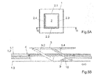
- the roof window 2 is rectangular and has four sides 2.1, 2.2, 2.3 and 2.4.
- the first side 2.1 and the second side 2.2 have the opening mechanism of the roof window 2.
- the third page 2.3 is the side of the roof window 2, over which a window sash 3 of the roof window 2 is moved to the side when opening.
- page 2.3 is the lower side
- the fourth page 2.4 is the upper side
- pages 2.1 and 2.2 are each the lateral sides of the roof window 2 mounted in the sloped roof 1.
- this invention is not limited to this arrangement.
- the roof window 2 can be installed rotated by 90 °, 180 ° or 270 ° in the roof 1.
- each of the four sides 2.1, 2.2, 2.3 and 2.4 can be arranged on the lower side of the recess of the roof 1. It is it is advantageous to attach the opening side 2.3 on the right or left side of the recess of the roof 1, ie not on the upper or lower side of the recess of the roof 1, since so part of the gravity does not act in the direction of movement and thus less force must be expended, to raise the sash 3.
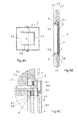
- the roof window 2 has a sash 3 and a window frame 4, as in Fig. 4C and 6C easy to recognize.
- all parts of the roof window 2, which move when the window is opened, are assigned as belonging to the wing, and all parts of the window which remain fixed when the window is opened are defined as belonging to the frame 4.
- the window sash 3 has in this embodiment, a sash and a window glass 3.4.
- the casement is L-shaped and consists of a first part 3.1, a second part of 3. 2 and a third insulating part 3.3, which connects the first part 3.1 with the second part 3.2.
- the window glass 3.4 is mounted on the outside of the sash or on the outside of the first part 3.1 and the third part 3.3.
- the window frame 4 has an outer frame 7 and an inner frame 8 in this embodiment.
- the outer frame 7 serves for the supporting connection of the roof window 2 with the roof construction 1.2.
- the inner frame 8 is supported by the outer frame 7 and is connected to the inner wall 1.3, so that the inner frame 8 forms the recess of the roof 1 for the roof window 2 in the installed state.
- the outer frame 7 has a first part 7.1, which is connected to the roof structure 1.2.
- the first part 7.1 is connected to a second part 7.2 via an insulating third part 7.3.
- the outer frame 7 and the second part 7.2 forms a first bearing surface of the window frame 4.
- the inner frame 8 on a first part 8.1, which is connected to the wall 1.3.
- the first part 8.1 is with a second part 8.2 on a insulating third part 8.3 connected.
- the inner frame 8 and the second part 8.2 forms a second bearing surface of the window frame 4.
- the first and second support surface of the window frame 4 and / or the window sash 3 has a seal 6 to close the roof window 2 in the closed state sealing.
- the inner frame 8 ends thereby lower than the outer frame 7, so that the second bearing surface of the window frame 4 is arranged lower than the first bearing surface of the window frame 4.
- the first and second bearing surface of the window sash 3 are arranged so that the first bearing surfaces lie on one another and the second bearing surfaces lie on one another.
- the window frame 4 is placed so deep in the roof structure 1.2, that the first and second bearing surface of the window frame 4 are below the roof covering 1.1. This ensures that the outside of the window sash 3 in the closed state in the roof level or slightly above or slightly below.
- the roof window 2 also has an opening mechanism.
- the opening mechanism has four lever arms 5.1, 5.2, 5.3 and 5.4.
- Each lever arm 5.1, 5.2, 5.3 and 5.4 is rotatably mounted at one end to the window frame 4 and at the opposite end to the window sash 3.
- the axes of rotation of the lever arms 5.1, 5.2, 5.3 and 5.4 in the window frame 4 and in the sash 3 are parallel to each other.
- the axes of rotation of the lever arms 5.1, 5.2, 5.3 and 5.4 are parallel to the sides 2.3 and / or 2.4 and perpendicular to the sides 2.1 and 2.2.
- the first lever arm 5.1 and the third lever arm 5.3 are arranged on the first page 2.1 of the roof window 2.
- the first lever arm 5.1 is mounted on the end of the first side 2.1 of the window frame 4 pointing towards the opening side 2.3 and in the middle of the first side 2.1 of the window sash 3.
- the third lever arm 5.3 is mounted in the middle of the first side 2.1 of the window frame 4 and at the end of the first side 2.1 of the window sash 3 pointing to the side 2.4.
- the fourth lever arm 5.4 is mounted on the opening side 2.3 facing end of the second side 2.2 of the window frame and in the middle of the second side 2.2 of the window sash 3.
- the second lever arm 5.2 is in the middle of the second side 2.2 of the Window frame 4 and mounted on the side facing 2.4 to the end of the second side 2.2 of the window sash 3.
- the lever arms 5.1, 5.2, 5.3 and 5.4 have between the storage on the window frame 4 and the storage at the sash 3 each the same distance.
- the bearing points of the lever arms 5.1 and 5.3 on the first side 2.1 and the lever arms 5.2 and 5.4 on the second side are arranged mirror-symmetrically to the symmetry axis of the roof window 2, which is arranged parallel to the first side 2.1 and / or second side 2.2 of the roof window 2 ,
- the length of the lever arms 5.1, 5.2, 5.3 and 5.4 corresponds to approximately half the length of the first side 2.1 and / or second side 2.2, or more precisely approximately half of the first side 2.1 of a window opening released by the window frame 4.
- the length of the lever arms 5.1, 5.2, 5.3 and 5.4 and / or the distance between the bearings of the lever arms 5.1, 5.2, 5.3 and 5.4 preferably corresponds to more than 40% of the length of the first side 2.1 of a window opening released by the window frame 4.
- the first lever arm 5.1 in particular more than 45%.
- the length should also not be too long, otherwise by the longer lever a greater force is needed to raise the sash 3 and the bearing points of the two lever arms one side of the sash 3 must be arranged closer together and thus suffers the stability of the sash 3 ,
- the length should be shorter than 60% of the length of the side 2.1 of the window opening.
- the first lever arm 5.1 is offset so arranged next to the third lever arm 5.3, that in the closed state of the bearing point of the first lever arm 5.1 in the middle of the sash 3 and the bearing point of the third lever arm 5.3 are arranged in the middle of the window frame 4 at the same height ,
- the bearing point of the first lever arm 5.1 in the middle of the window sash 3 in the direction of the side 2.1 even between the bearing point of the third lever arm 5.3 in the middle of the window frame 4 and the bearing point of the third lever arm 5.3 pointing to the side 2.4 End of the first page 2.1 of the window sash 3 arranged.
- the second and fourth lever arms 5.2 and 5.4 on the second side 2.2 are arranged accordingly. This juxtaposition of the two lever arms of one side allows a lever length of 50% or more of the length of the side 2.1 of the window opening.
- the four lever arms rotate 5.1, 5.2, 5.3 and 5.4.
- the bearing points of the lever arms 5.1, 5.2, 5.3 and 5.4 move on the window sash in each case on a circular path with a radius corresponding to the distance between the bearing points in the lever arms 5.1, 5.2, 5.3 and 5.4.
- the sash 4 moves parallel to its position in the closed state or parallel to the roof surface. This offers the rooftop 1 stroking wind no attack surface.
- the window sash 3 can be easily lifted out of the roof surface and stored with the same movement laterally next to the window opening of the roof window 2 on the roof surface.
- the movement of the sash 3 between the closed and the open state thus completes a semi-circular motion.
- Semicircular motion means that the trajectory of the sash 3 follows a circular path and thereby first removed from the roof surface and / or the plane of the sash in the closed state and then approaches this roof surface / level again. It is important for the invention that the lever arms 5.1, 5.2, 5.3 and 5.4 continue to rotate over the vertical position of the lever arms 5.1, 5.2, 5.3 and 5.4, so that the window sash 3 approaches the roof surface again.
- Each orientation or angle of the lever arms 5.1, 5.2, 5.3 and 5.4 refers to the longitudinal axis of the lever arms 5.1, 5.2, 5.3 and 5.4 passing through the two bearing points of each lever arm 5.1, 5.2, 5.3 and 5.4.
- the vertical position of the lever arm 5.1, 5.2, 5.3 and 5.4 refers to the position in which the lever arm 5.1, 5.2, 5.3 and 5.4 is perpendicular to the roof surface.
- Fig. 11 shows a diagram that sets the angle of the lever arms 5.1, 5.2, 5.3 and 5.4 and the roof surface between 0 ° and 180 ° in connection with the already pushed out of the window opening portion of the surface of the window sash 3. It was assumed here that the angle of the lever arms 5.1, 5.2, 5.3 and 5.4 starts at 0 ° and that the length of the lever arms between the two bearing points is exactly half of the window opening. It is very nice to see that just at the beginning the rotation shows the movement mainly in vertical direction and hardly parallel to the roof surface shows. Especially in the lever positions between 40 ° and 140 ° 75% of the horizontal movement is realized.
- the semi-circular movement of the lever arms 5.1, 5.2, 5.3 and 5.4 is so important because up to the 90% position, the sash 3 is only 50% pushed out of the roof window opening.
- the window sash 3 can already be pushed up to 75% out of the window opening, with lever positions of up to 130 ° to 82%, with lever positions of up to 140 ° to 88%, with lever positions of up to 150 ° 93%, with lever positions of up to 160 ° to 97% and with lever positions of up to 170 ° to 99%.
- the lever arm positions are limited by the support of the lever arms 5.1, 5.2, 5.3 and 5.4 on the roof surface. It is desirable to move the window sash 3 more than 70%, in particular more than 80%, in particular more than 90%, in particular more than 95%, out of the window opening.
- the Hebelarm ein in the open Condition about 170 °. Preferably, this angle is defined by the support of the lever arms 5.1, 5.2, 5.3 and 5.4 on the roof surface.
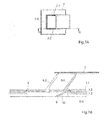
- Fig. 9B shows now the open position of the sash 3 of the roof window 2.
- the lever arms 5.1, 5.2, 5.3 and 5.4 are not straight, but in the direct line between the bearing points on the window frame 4 and the window sash 3 a Recess which is formed in the open state, the window frame 4 and the roof 1 to exclude. Therefore, the lever arms 5.1, 5.2, 5.3 and 5.4 are roughly L-shaped.
- the short section is at least as high as the distance between the bearing point of the lever arm 5.1 and 5.4 in the window frame 4 and the roof surface.
- the long portion of the lever arm 5.1 and 5.4 can be formed in the open position parallel to the roof surface.
- the window sash 3 is supported in the open position by a support of the entire longitudinal side of the two lever arms 5.1 and 5.4. Due to the flat support of the two lever arms 5.1 and 5.4, the weight of the sash 3 is evenly distributed on the roof covering 1.3 and not concentrated on one edge of the roof covering 1.3, which could damage the roofing 1.3.
- the sash 3 in the open position need not be deposited on the roof surface, but may also be held in the open position by a motor, a fastener or a stop in the opening mechanism or by a spring.
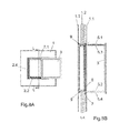
- the roof window 2 preferably has a motor 9 which is designed to rotate at least one of the four lever arms 5.1, 5.2, 5.3 and 5.4 about a bearing axis.
- the first lever arm 5.1 and the fourth lever arm 5.4 are each driven by a motor 9.
- the motor 9 drives the bearing axes of the first lever arm 5.1 and the fourth lever arm 5.4 in the window frame 4 in this embodiment.
- the motor axis is parallel to the bearing axis of the lever arms 5.1 and 5.4 and is transmitted via a V-belt 10 on the bearing axis.
- many other forms of the motor-driven drive a bearing axis of the lever arms 5.1, 5.2, 5.3 and 5.4 possible.
- the roof window is 150 cm x 150 cm in size.
- the lever arm is about 75 cm long and thus a very high force is needed to lift the window sash and then decelerate again when lowering. Therefore, it is advantageous to keep the sash 3 sideways to the sloping roof, i. perpendicular to the gradient of the roof pitch and in the roof level, to move.
- already a part of the weight of the sash does not work in the opening and closing direction, but in the direction of the bearing axes of the lever arms 5.1, 5.2, 5.3 and 5.4.
- the force of the motor could be assisted by spring means which, upon lifting the sash, provide a supporting force in the direction of rotation and when lowered cause a braking force in the direction of rotation.
- spring means which, upon lifting the sash, provide a supporting force in the direction of rotation and when lowered cause a braking force in the direction of rotation.
- This could be realized, for example, by converting the rotation of the bearing axes of the third lever arm 5.3 and the second lever arm 5.2 into a straight bar, e.g. over a rack.
- the rod could be attached at one end to a first spring, e.g. a gas spring, abut, the rod detaches from a certain point of the first spring and pushes with the opposite end to a spring, which acts a force in the opposite direction. This could reduce the force on the engine.
Landscapes
- Engineering & Computer Science (AREA)
- Architecture (AREA)
- Civil Engineering (AREA)
- Structural Engineering (AREA)
- Wing Frames And Configurations (AREA)
Priority Applications (1)
| Application Number | Priority Date | Filing Date | Title |
|---|---|---|---|
| EP13182686.9A EP2843149B1 (fr) | 2013-09-02 | 2013-09-02 | Lucarne avec mécanisme d'ouverture |
Applications Claiming Priority (1)
| Application Number | Priority Date | Filing Date | Title |
|---|---|---|---|
| EP13182686.9A EP2843149B1 (fr) | 2013-09-02 | 2013-09-02 | Lucarne avec mécanisme d'ouverture |
Publications (2)
| Publication Number | Publication Date |
|---|---|
| EP2843149A1 true EP2843149A1 (fr) | 2015-03-04 |
| EP2843149B1 EP2843149B1 (fr) | 2018-11-07 |
Family
ID=49080805
Family Applications (1)
| Application Number | Title | Priority Date | Filing Date |
|---|---|---|---|
| EP13182686.9A Active EP2843149B1 (fr) | 2013-09-02 | 2013-09-02 | Lucarne avec mécanisme d'ouverture |
Country Status (1)
| Country | Link |
|---|---|
| EP (1) | EP2843149B1 (fr) |
Cited By (5)
| Publication number | Priority date | Publication date | Assignee | Title |
|---|---|---|---|---|
| CN109958239A (zh) * | 2017-12-22 | 2019-07-02 | 北京金峰多玛节能环保技术有限公司 | 一种自动提升平移天窗 |
| CN112900755A (zh) * | 2021-01-14 | 2021-06-04 | 重庆交通大学 | 一种用于绿色建筑的天窗结构 |
| CZ309025B6 (cs) * | 2020-10-14 | 2021-12-01 | České vysoké učení technické v Praze | Střešní okno mající okenní křídlo otevíratelné do exteriéru do polohy rovnoběžné s rovinou střechy |
| CN114809464A (zh) * | 2022-04-28 | 2022-07-29 | 江苏环亚医用科技集团股份有限公司 | 一种可开启式防火天窗电控圆弧输送轨道 |
| CN117261564A (zh) * | 2023-11-23 | 2023-12-22 | 江苏德福来汽车部件有限公司 | 一种天窗挡风网低噪音清洁结构 |
Citations (7)
| Publication number | Priority date | Publication date | Assignee | Title |
|---|---|---|---|---|
| DE201715C (fr) * | ||||
| GB449761A (en) * | 1933-12-30 | 1936-06-29 | Koller Ernst | Improved windows, doors and the like movable on parallel links |
| CH306301A (de) * | 1952-09-23 | 1955-04-15 | Ag A Kully | Lüftungsfenster mit Verstellvorrichtung. |
| DE3218622A1 (de) * | 1982-05-18 | 1983-11-24 | Grescha-Gesellschaft mbH & Co Grefe & Scharf, 4817 Leopoldshöhe | Lueftungs- und rauchabzugskuppel fuer flachdaecher |
| JPH02240353A (ja) * | 1989-03-14 | 1990-09-25 | Nabuko Syst Kk | 天窓装置 |
| WO1991019070A1 (fr) * | 1990-05-29 | 1991-12-12 | Stephen William Emanuel | Installations architecturales telles que des fenetres et des portes |
| DE29921090U1 (de) * | 1999-12-01 | 2001-04-12 | Stuermann Gmbh & Co | Rauchabzugs- oder Lüftungsklappe |
Family Cites Families (2)
| Publication number | Priority date | Publication date | Assignee | Title |
|---|---|---|---|---|
| US4064649A (en) * | 1975-06-03 | 1977-12-27 | V. Kann Rasmussen & Co. | Window, particularly intended for installation in an inclined or flat roof |
| JPS63169687U (fr) * | 1987-04-24 | 1988-11-04 |
-
2013
- 2013-09-02 EP EP13182686.9A patent/EP2843149B1/fr active Active
Patent Citations (7)
| Publication number | Priority date | Publication date | Assignee | Title |
|---|---|---|---|---|
| DE201715C (fr) * | ||||
| GB449761A (en) * | 1933-12-30 | 1936-06-29 | Koller Ernst | Improved windows, doors and the like movable on parallel links |
| CH306301A (de) * | 1952-09-23 | 1955-04-15 | Ag A Kully | Lüftungsfenster mit Verstellvorrichtung. |
| DE3218622A1 (de) * | 1982-05-18 | 1983-11-24 | Grescha-Gesellschaft mbH & Co Grefe & Scharf, 4817 Leopoldshöhe | Lueftungs- und rauchabzugskuppel fuer flachdaecher |
| JPH02240353A (ja) * | 1989-03-14 | 1990-09-25 | Nabuko Syst Kk | 天窓装置 |
| WO1991019070A1 (fr) * | 1990-05-29 | 1991-12-12 | Stephen William Emanuel | Installations architecturales telles que des fenetres et des portes |
| DE29921090U1 (de) * | 1999-12-01 | 2001-04-12 | Stuermann Gmbh & Co | Rauchabzugs- oder Lüftungsklappe |
Cited By (9)
| Publication number | Priority date | Publication date | Assignee | Title |
|---|---|---|---|---|
| CN109958239A (zh) * | 2017-12-22 | 2019-07-02 | 北京金峰多玛节能环保技术有限公司 | 一种自动提升平移天窗 |
| CN109958239B (zh) * | 2017-12-22 | 2024-01-05 | 北京金峰多玛节能环保技术有限公司 | 一种自动提升平移天窗 |
| CZ309025B6 (cs) * | 2020-10-14 | 2021-12-01 | České vysoké učení technické v Praze | Střešní okno mající okenní křídlo otevíratelné do exteriéru do polohy rovnoběžné s rovinou střechy |
| EP3985192A1 (fr) | 2020-10-14 | 2022-04-20 | Ceske vysoke uceni technicke v Praze | Fenêtre de toit comportant un battant pouvant s'ouvrir vers l'extérieur dans une position parallèle au plan du toit |
| CN112900755A (zh) * | 2021-01-14 | 2021-06-04 | 重庆交通大学 | 一种用于绿色建筑的天窗结构 |
| CN114809464A (zh) * | 2022-04-28 | 2022-07-29 | 江苏环亚医用科技集团股份有限公司 | 一种可开启式防火天窗电控圆弧输送轨道 |
| CN114809464B (zh) * | 2022-04-28 | 2023-04-25 | 江苏环亚医用科技集团股份有限公司 | 一种可开启式防火天窗电控圆弧输送轨道 |
| CN117261564A (zh) * | 2023-11-23 | 2023-12-22 | 江苏德福来汽车部件有限公司 | 一种天窗挡风网低噪音清洁结构 |
| CN117261564B (zh) * | 2023-11-23 | 2024-02-27 | 江苏德福来汽车部件有限公司 | 一种天窗挡风网低噪音清洁结构 |
Also Published As
| Publication number | Publication date |
|---|---|
| EP2843149B1 (fr) | 2018-11-07 |
Similar Documents
| Publication | Publication Date | Title |
|---|---|---|
| EP2843149B1 (fr) | Lucarne avec mécanisme d'ouverture | |
| EP2698495B1 (fr) | Porte | |
| DE2635480A1 (de) | Schiebefenster mit wetterdichter abdichtung | |
| AT15365U1 (de) | Verglasungssystem | |
| EP3816387B1 (fr) | Fenêtre coulissante de toiture du bâtiment | |
| EP1555379A1 (fr) | Rideau à lammes | |
| DE2352869A1 (de) | Hebe-dreh-tuer | |
| EP1555380A1 (fr) | Rideau à lammes | |
| CH654373A5 (en) | Window shutter | |
| DE102013109293B3 (de) | Verschlusselement | |
| EP1039091B1 (fr) | Revêtement d'une surface de mur ou de toit | |
| CH630992A5 (en) | Window having a sash which can be tilted and horizontally displaced | |
| DE19715712C2 (de) | Sektionaltor | |
| DE102005052247B4 (de) | Treib- oder Lagerhaus mit doppeltem Luftfenster oder Dachflügeln | |
| DE10123565C1 (de) | Lamellenfläche für ein Gebäude | |
| EP2666951A1 (fr) | Construction à lamelles pour installations du bâtiment | |
| DE3343498C2 (de) | Dachelement | |
| EP1225286B1 (fr) | Couverture extensible pour véranda | |
| DE2756475A1 (de) | Schattierungseinrichtung fuer ein gewaechshaus | |
| DE3841904C2 (fr) | ||
| DE102007024676A1 (de) | Fensterbeschlag mit einem Ritzel-Zahnstangenantrieb zur Bewegung eines Fensterrahmens in einem Blendrahmen | |
| CH688593A5 (de) | Faltbare Vorrichtung zum Verschliessen von Gebaeude oeffnungen, insbesondere fuer ein Faltdach oder Falttor. | |
| DE102009014579A1 (de) | Drehgelenk für Faltläden | |
| DE202005019854U1 (de) | Tor | |
| DE102012011931B4 (de) | Lauftor, insbesondere Seitenlauftor |
Legal Events
| Date | Code | Title | Description |
|---|---|---|---|
| 17P | Request for examination filed |
Effective date: 20140324 |
|
| AK | Designated contracting states |
Kind code of ref document: A1 Designated state(s): AL AT BE BG CH CY CZ DE DK EE ES FI FR GB GR HR HU IE IS IT LI LT LU LV MC MK MT NL NO PL PT RO RS SE SI SK SM TR |
|
| AX | Request for extension of the european patent |
Extension state: BA ME |
|
| PUAI | Public reference made under article 153(3) epc to a published international application that has entered the european phase |
Free format text: ORIGINAL CODE: 0009012 |
|
| 17Q | First examination report despatched |
Effective date: 20160425 |
|
| RIC1 | Information provided on ipc code assigned before grant |
Ipc: E04D 13/035 20060101AFI20160418BHEP |
|
| STAA | Information on the status of an ep patent application or granted ep patent |
Free format text: STATUS: EXAMINATION IS IN PROGRESS |
|
| GRAP | Despatch of communication of intention to grant a patent |
Free format text: ORIGINAL CODE: EPIDOSNIGR1 |
|
| STAA | Information on the status of an ep patent application or granted ep patent |
Free format text: STATUS: GRANT OF PATENT IS INTENDED |
|
| INTG | Intention to grant announced |
Effective date: 20171017 |
|
| GRAJ | Information related to disapproval of communication of intention to grant by the applicant or resumption of examination proceedings by the epo deleted |
Free format text: ORIGINAL CODE: EPIDOSDIGR1 |
|
| STAA | Information on the status of an ep patent application or granted ep patent |
Free format text: STATUS: EXAMINATION IS IN PROGRESS |
|
| GRAP | Despatch of communication of intention to grant a patent |
Free format text: ORIGINAL CODE: EPIDOSNIGR1 |
|
| STAA | Information on the status of an ep patent application or granted ep patent |
Free format text: STATUS: GRANT OF PATENT IS INTENDED |
|
| INTC | Intention to grant announced (deleted) | ||
| INTG | Intention to grant announced |
Effective date: 20180323 |
|
| GRAS | Grant fee paid |
Free format text: ORIGINAL CODE: EPIDOSNIGR3 |
|
| GRAA | (expected) grant |
Free format text: ORIGINAL CODE: 0009210 |
|
| STAA | Information on the status of an ep patent application or granted ep patent |
Free format text: STATUS: THE PATENT HAS BEEN GRANTED |
|
| AK | Designated contracting states |
Kind code of ref document: B1 Designated state(s): AL AT BE BG CH CY CZ DE DK EE ES FI FR GB GR HR HU IE IS IT LI LT LU LV MC MK MT NL NO PL PT RO RS SE SI SK SM TR |
|
| REG | Reference to a national code |
Ref country code: GB Ref legal event code: FG4D Free format text: NOT ENGLISH |
|
| REG | Reference to a national code |
Ref country code: CH Ref legal event code: EP Ref country code: AT Ref legal event code: REF Ref document number: 1062203 Country of ref document: AT Kind code of ref document: T Effective date: 20181115 |
|
| REG | Reference to a national code |
Ref country code: IE Ref legal event code: FG4D Free format text: LANGUAGE OF EP DOCUMENT: GERMAN |
|
| REG | Reference to a national code |
Ref country code: DE Ref legal event code: R096 Ref document number: 502013011527 Country of ref document: DE |
|
| REG | Reference to a national code |
Ref country code: CH Ref legal event code: NV Representative=s name: P&TS SA, CH |
|
| REG | Reference to a national code |
Ref country code: NL Ref legal event code: MP Effective date: 20181107 |
|
| REG | Reference to a national code |
Ref country code: LT Ref legal event code: MG4D |
|
| PG25 | Lapsed in a contracting state [announced via postgrant information from national office to epo] |
Ref country code: IS Free format text: LAPSE BECAUSE OF FAILURE TO SUBMIT A TRANSLATION OF THE DESCRIPTION OR TO PAY THE FEE WITHIN THE PRESCRIBED TIME-LIMIT Effective date: 20190307 Ref country code: ES Free format text: LAPSE BECAUSE OF FAILURE TO SUBMIT A TRANSLATION OF THE DESCRIPTION OR TO PAY THE FEE WITHIN THE PRESCRIBED TIME-LIMIT Effective date: 20181107 Ref country code: BG Free format text: LAPSE BECAUSE OF FAILURE TO SUBMIT A TRANSLATION OF THE DESCRIPTION OR TO PAY THE FEE WITHIN THE PRESCRIBED TIME-LIMIT Effective date: 20190207 Ref country code: LT Free format text: LAPSE BECAUSE OF FAILURE TO SUBMIT A TRANSLATION OF THE DESCRIPTION OR TO PAY THE FEE WITHIN THE PRESCRIBED TIME-LIMIT Effective date: 20181107 Ref country code: HR Free format text: LAPSE BECAUSE OF FAILURE TO SUBMIT A TRANSLATION OF THE DESCRIPTION OR TO PAY THE FEE WITHIN THE PRESCRIBED TIME-LIMIT Effective date: 20181107 Ref country code: LV Free format text: LAPSE BECAUSE OF FAILURE TO SUBMIT A TRANSLATION OF THE DESCRIPTION OR TO PAY THE FEE WITHIN THE PRESCRIBED TIME-LIMIT Effective date: 20181107 Ref country code: NO Free format text: LAPSE BECAUSE OF FAILURE TO SUBMIT A TRANSLATION OF THE DESCRIPTION OR TO PAY THE FEE WITHIN THE PRESCRIBED TIME-LIMIT Effective date: 20190207 Ref country code: FI Free format text: LAPSE BECAUSE OF FAILURE TO SUBMIT A TRANSLATION OF THE DESCRIPTION OR TO PAY THE FEE WITHIN THE PRESCRIBED TIME-LIMIT Effective date: 20181107 |
|
| PG25 | Lapsed in a contracting state [announced via postgrant information from national office to epo] |
Ref country code: NL Free format text: LAPSE BECAUSE OF FAILURE TO SUBMIT A TRANSLATION OF THE DESCRIPTION OR TO PAY THE FEE WITHIN THE PRESCRIBED TIME-LIMIT Effective date: 20181107 Ref country code: SE Free format text: LAPSE BECAUSE OF FAILURE TO SUBMIT A TRANSLATION OF THE DESCRIPTION OR TO PAY THE FEE WITHIN THE PRESCRIBED TIME-LIMIT Effective date: 20181107 Ref country code: AL Free format text: LAPSE BECAUSE OF FAILURE TO SUBMIT A TRANSLATION OF THE DESCRIPTION OR TO PAY THE FEE WITHIN THE PRESCRIBED TIME-LIMIT Effective date: 20181107 Ref country code: GR Free format text: LAPSE BECAUSE OF FAILURE TO SUBMIT A TRANSLATION OF THE DESCRIPTION OR TO PAY THE FEE WITHIN THE PRESCRIBED TIME-LIMIT Effective date: 20190208 Ref country code: RS Free format text: LAPSE BECAUSE OF FAILURE TO SUBMIT A TRANSLATION OF THE DESCRIPTION OR TO PAY THE FEE WITHIN THE PRESCRIBED TIME-LIMIT Effective date: 20181107 Ref country code: PT Free format text: LAPSE BECAUSE OF FAILURE TO SUBMIT A TRANSLATION OF THE DESCRIPTION OR TO PAY THE FEE WITHIN THE PRESCRIBED TIME-LIMIT Effective date: 20190307 |
|
| PG25 | Lapsed in a contracting state [announced via postgrant information from national office to epo] |
Ref country code: CZ Free format text: LAPSE BECAUSE OF FAILURE TO SUBMIT A TRANSLATION OF THE DESCRIPTION OR TO PAY THE FEE WITHIN THE PRESCRIBED TIME-LIMIT Effective date: 20181107 Ref country code: IT Free format text: LAPSE BECAUSE OF FAILURE TO SUBMIT A TRANSLATION OF THE DESCRIPTION OR TO PAY THE FEE WITHIN THE PRESCRIBED TIME-LIMIT Effective date: 20181107 Ref country code: DK Free format text: LAPSE BECAUSE OF FAILURE TO SUBMIT A TRANSLATION OF THE DESCRIPTION OR TO PAY THE FEE WITHIN THE PRESCRIBED TIME-LIMIT Effective date: 20181107 Ref country code: PL Free format text: LAPSE BECAUSE OF FAILURE TO SUBMIT A TRANSLATION OF THE DESCRIPTION OR TO PAY THE FEE WITHIN THE PRESCRIBED TIME-LIMIT Effective date: 20181107 |
|
| REG | Reference to a national code |
Ref country code: DE Ref legal event code: R097 Ref document number: 502013011527 Country of ref document: DE |
|
| PG25 | Lapsed in a contracting state [announced via postgrant information from national office to epo] |
Ref country code: SK Free format text: LAPSE BECAUSE OF FAILURE TO SUBMIT A TRANSLATION OF THE DESCRIPTION OR TO PAY THE FEE WITHIN THE PRESCRIBED TIME-LIMIT Effective date: 20181107 Ref country code: RO Free format text: LAPSE BECAUSE OF FAILURE TO SUBMIT A TRANSLATION OF THE DESCRIPTION OR TO PAY THE FEE WITHIN THE PRESCRIBED TIME-LIMIT Effective date: 20181107 Ref country code: EE Free format text: LAPSE BECAUSE OF FAILURE TO SUBMIT A TRANSLATION OF THE DESCRIPTION OR TO PAY THE FEE WITHIN THE PRESCRIBED TIME-LIMIT Effective date: 20181107 Ref country code: SM Free format text: LAPSE BECAUSE OF FAILURE TO SUBMIT A TRANSLATION OF THE DESCRIPTION OR TO PAY THE FEE WITHIN THE PRESCRIBED TIME-LIMIT Effective date: 20181107 |
|
| PLBE | No opposition filed within time limit |
Free format text: ORIGINAL CODE: 0009261 |
|
| STAA | Information on the status of an ep patent application or granted ep patent |
Free format text: STATUS: NO OPPOSITION FILED WITHIN TIME LIMIT |
|
| 26N | No opposition filed |
Effective date: 20190808 |
|
| PG25 | Lapsed in a contracting state [announced via postgrant information from national office to epo] |
Ref country code: SI Free format text: LAPSE BECAUSE OF FAILURE TO SUBMIT A TRANSLATION OF THE DESCRIPTION OR TO PAY THE FEE WITHIN THE PRESCRIBED TIME-LIMIT Effective date: 20181107 |
|
| PG25 | Lapsed in a contracting state [announced via postgrant information from national office to epo] |
Ref country code: TR Free format text: LAPSE BECAUSE OF FAILURE TO SUBMIT A TRANSLATION OF THE DESCRIPTION OR TO PAY THE FEE WITHIN THE PRESCRIBED TIME-LIMIT Effective date: 20181107 |
|
| REG | Reference to a national code |
Ref country code: DE Ref legal event code: R119 Ref document number: 502013011527 Country of ref document: DE |
|
| PG25 | Lapsed in a contracting state [announced via postgrant information from national office to epo] |
Ref country code: MC Free format text: LAPSE BECAUSE OF FAILURE TO SUBMIT A TRANSLATION OF THE DESCRIPTION OR TO PAY THE FEE WITHIN THE PRESCRIBED TIME-LIMIT Effective date: 20181107 |
|
| PG25 | Lapsed in a contracting state [announced via postgrant information from national office to epo] |
Ref country code: LU Free format text: LAPSE BECAUSE OF NON-PAYMENT OF DUE FEES Effective date: 20190902 Ref country code: IE Free format text: LAPSE BECAUSE OF NON-PAYMENT OF DUE FEES Effective date: 20190902 Ref country code: DE Free format text: LAPSE BECAUSE OF NON-PAYMENT OF DUE FEES Effective date: 20200401 |
|
| REG | Reference to a national code |
Ref country code: BE Ref legal event code: MM Effective date: 20190930 |
|
| PG25 | Lapsed in a contracting state [announced via postgrant information from national office to epo] |
Ref country code: BE Free format text: LAPSE BECAUSE OF NON-PAYMENT OF DUE FEES Effective date: 20190930 |
|
| GBPC | Gb: european patent ceased through non-payment of renewal fee |
Effective date: 20190902 |
|
| PG25 | Lapsed in a contracting state [announced via postgrant information from national office to epo] |
Ref country code: FR Free format text: LAPSE BECAUSE OF NON-PAYMENT OF DUE FEES Effective date: 20190930 Ref country code: GB Free format text: LAPSE BECAUSE OF NON-PAYMENT OF DUE FEES Effective date: 20190902 |
|
| REG | Reference to a national code |
Ref country code: AT Ref legal event code: MM01 Ref document number: 1062203 Country of ref document: AT Kind code of ref document: T Effective date: 20190902 |
|
| PG25 | Lapsed in a contracting state [announced via postgrant information from national office to epo] |
Ref country code: AT Free format text: LAPSE BECAUSE OF NON-PAYMENT OF DUE FEES Effective date: 20190902 |
|
| PG25 | Lapsed in a contracting state [announced via postgrant information from national office to epo] |
Ref country code: CY Free format text: LAPSE BECAUSE OF FAILURE TO SUBMIT A TRANSLATION OF THE DESCRIPTION OR TO PAY THE FEE WITHIN THE PRESCRIBED TIME-LIMIT Effective date: 20181107 |
|
| PG25 | Lapsed in a contracting state [announced via postgrant information from national office to epo] |
Ref country code: MT Free format text: LAPSE BECAUSE OF FAILURE TO SUBMIT A TRANSLATION OF THE DESCRIPTION OR TO PAY THE FEE WITHIN THE PRESCRIBED TIME-LIMIT Effective date: 20181107 Ref country code: HU Free format text: LAPSE BECAUSE OF FAILURE TO SUBMIT A TRANSLATION OF THE DESCRIPTION OR TO PAY THE FEE WITHIN THE PRESCRIBED TIME-LIMIT; INVALID AB INITIO Effective date: 20130902 |
|
| PG25 | Lapsed in a contracting state [announced via postgrant information from national office to epo] |
Ref country code: MK Free format text: LAPSE BECAUSE OF FAILURE TO SUBMIT A TRANSLATION OF THE DESCRIPTION OR TO PAY THE FEE WITHIN THE PRESCRIBED TIME-LIMIT Effective date: 20181107 |
|
| PGFP | Annual fee paid to national office [announced via postgrant information from national office to epo] |
Ref country code: CH Payment date: 20231001 Year of fee payment: 11 |